Abstract
Epoxy adhesives, widely used in multiple structural applications, are used in the milling tool industry to replace brazing and mechanical fastening when joining the cutting bits to the tool body; though their durability is still a concern. This work aims to evaluate and characterise the effect of environmental factors associated with a tool’s life cycle on the performance of these bonded joints. A gravimetric analysis was conducted on bulk adhesive plates for water, cutting emulsion and dielectric fluid to obtain diffusion and relaxation rates. Novel real joint shear specimens were developed to enable strength testing on joints which are comparable with the final application. These specimens were immersed in fluids and subjected to thermal cycles or a corrosive finishing surface treatment to simulate the tool’s life cycle. The joint’s resistance was then benchmarked. Lastly, a dimensional variation test was carried out on tool prototypes before and after ageing, showing no significant dimensional variation which could compromise the cutting performance of the tool. Overall, though it was possible to identify a decrease in strength of around 20% in most tests, joint strength was still within the values necessary for safe operation, with a large safety factor still being retained.
1. Introduction
The use of adhesive bonding in the manufacturing of machining tools is well documented, having been a topic of study for over 40 years; though publication regarding this process has waned in the last decade. Most investigations have been devoted to assessing the thermal behaviour [1,2,3,4] of the bonded joint integrated in the cutting tool or to the determination of the quality of cut and surface finish [5,6,7]. Other works have sought to obtain improvements in the joint capabilities via the addition of metallic and other conductive powders, increasing the thermal [8,9] and electrical [10] conductivity. However, until now the use of adhesives in machining tools has been very limited, since many of the limitations inherent to this technique have never been fully addressed.
In more recent years, studies performed by Correia et al. [11,12,13] and Gomes et al. [14], have shown that adhesive bonding can serve as a substitute for brazing in woodworking tools, an application where the temperature, environmental conditions and the cutting loads are much more favourable for adhesive bonding. As a result, a much lighter tool can be obtained, because adhesive bonding facilitates the shift from steel to aluminium bodies, while maintaining a high strength safety factor, sufficient thermal resistance and the capability to be sharpened by non-thermal/contact methods, i.e., electrical discharge machining (EDM).
However, these works do not address the long-term durability of this solution. For this, it is necessary to systematically characterise the effects of all the possible joint degradation phenomena present in the entire life cycle of a milling tool. The first step in this process consists of the definition of a typical life cycle for these types of tools. This can be observed in Figure 1.
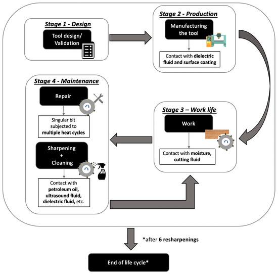
Figure 1.
Typical life cycle of milling tools.
A common tool life cycle is composed of four stages: the design (Stage 1), production (Stage 2), work life (Stage 3), and maintenance (Stage 4). Stages 3 and 4 alternate for a few cycles until a tool reaches its end of life.
The initial stage of joint design usually does not involve the assessment of degradation, but subsequent stages can affect joint durability. Therefore, designers must be aware of factors that can affect the joint’s lifespan when using bonded joints and account for any negative effects.
Stage 2 involves the manufacturing cycle of milling tools, which includes several processes such as saw cutting, turning, milling, grinding, and EDM. Surface coatings may also be applied for uniformity and strength but only for aesthetic purposes. These coatings do not contribute to initial joint strength but can contribute to degradation. Finally, the tool is sharpened using electric-discharge machining (EDM) to prepare it for service.
Stage 3 is the entire service life of the tool. Although the tools are mainly used in dry applications, such as woodworking, ambient moisture and temperature can still pose potential issues during this stage. To future-proof the concept, the possibility of wet milling, which involves contact with cutting emulsions, should also be considered for this stage.
The fourth stage of the tool’s lifecycle involves maintenance operations, including repair and cleaning/resharpening. When repairing the tool, it is important to determine whether individual cutting bits can be fixed or if all bonded cutting bits are affected and require reworking of all adhesive connections due to the possibility that multiple curing cycles have weakened the shear strength of the adhesive. The cleaning and resharpening operation involves several techniques, such as residue softening fluids and abrasive jets, which must be investigated for their impact on the shear strength of adhesive connections. The maintenance stage is crucial to ensuring the tool’s longevity and performance.
In the end, it becomes evident that the tool will be in contact with a variety of fluids and environments from the time of its initial design until the conclusion of its life cycle (generally speaking, after six resharpening cycles), reinforcing the need for this study.
Overall, the effects of high temperatures, corrosive environments and humidity have been long understood as detrimental to the long-term use of polymeric materials and require careful study [15]. In some way or another, all adhesives absorb water, and it is known that, for structural adhesives, the rate of water diffusion increases with temperature, following the Arrhenius equation [16,17,18].
The process of predicting the effects of fluid absorption and temperature on adhesives requires characterization of the diffusion methods within the joint. Sorption can be divided into two cases, diffusion-controlled and relaxation-controlled. If the diffusion rate is greater than the relaxation rate, it is called Fickian behaviour, and if the relaxation rate surpasses the diffusion in controlling the water uptake, it is known as non-Fickian behaviour [16,19]. The use of Fick’s law is suitable for Fickian processes, but for relaxation processes, a dual-Fickian model should be used instead. Structural epoxies may fall into this category. This model can approximate anomalous uptakes and take into account multiple equilibrium states in the sorption process. Various models exist under this category, but they are more numerically complex than Fick’s law [16,20].
Though there has been extensive published research to characterise the diffusion of water and its effects on polymeric materials, there has been limited research on the effects of common industrial fluids on the hygrothermal degradation of the adhesive connections. Similar research has been conducted for automotive applications, focusing on the effects of weather and motor oil. The findings of this research have been mixed, but generally indicate that the oils are less damaging to the adhesive than water [21].
Another concern that arises when one considers the production of adhesively bonded milling tools is the need for surface coatings, which in this case fulfil solely aesthetic purposes, but can also be instrumental to improve durability, minimising the effects of long-term corrosion. The main treatments used in steel tools are oxidation and nickel-plating, while anodization is used for aluminium tools. Both cases require long exposure to high-temperature chemical baths, which pose a threat to the strength of the bonded connections.
Additionally, adhesives and adhesive joints are also quite susceptible to temperature. When heated to high temperatures, residual thermal stresses are created in bonded joints due to the mismatch of the adherends’ and adhesive’s coefficients of thermal expansion (CTE). Cooling the joint can also lead to high interfacial stresses between the substrate and the adhesive layer. This results in a damaged mechanical response, which is negatively impacted by thermal cycles, and can result in a low-to-moderate reduction in their average failure load and stiffness [22,23]. Furthermore, Costa et al. [24] have shown that the adhesives’ poor resistance to high temperature, resulting from their polymeric nature, limits their use in many applications. Additionally, unrecoverable degradation will occur at higher temperatures, as the polymeric chains decompose. Thus, the repair process for damaged milling tool bits can negatively affect joint performance due to the application of heat to remove or cure the adhesive of the damaged bit, which exposes the adhesive of undamaged bits to multiple high-temperature cycles for each repair performed.
The adhesive considered for this work is a one-part heat curing epoxy, previously characterised by Correia et al. [11], and the ageing fluids that were tested were water, a lubricating cutting emulsion, dielectric fluid used in the bit’s electric discharge machining (EDM) sharpening process, and a petroleum oil plus an ultrasound fluid, both used for cleaning. A sandblast procedure was also tested for the maintenance stage, as a possible quick way to clean the tool. Gravimetric ageing of bulk plates was carried out on some of the fluids (water, cutting emulsion and dielectric fluid) and a dual-Fickian model was created in order to characterise their sorption process. Through Fourier transform infrared spectroscopy (FTIR), adhesive bulk plate samples were analysed to check for chemical changes during this unusual ageing process. Real joint shear (RJS) specimens were developed to simulate and test the effects of ageing in real joints. These were then immersed in the fluids under study in order to understand the effect of each one on the strength of the adhesive joints. Two types of immersion procedures were used: continuous and cyclic. This allowed the assessment of the joint degradation under long-term exposure to fluids and in cycles between service and maintenance. Finally, a study into the dimensional variations of the adhesive joints in a milling tool was carried out, assessing if the fluid uptake would have a negative effect on the standard dimensions of the tool.
2. Experimental Details
2.1. Materials
In this work, an epoxy adhesive was considered. This was adhesive was used to produce both bulk plates and the joints that bond steel or aluminium to polycrystalline diamond (PCD) bits. Additionally, multiple degradation mediums were used, and these are also described in this section.
2.1.1. Adhesive
The adhesive under study is a one-part, heat curing epoxy adhesive, doped with conductive microspheres [11]. The adhesive and its properties were sourced from the manufacturer’s datasheet, and from previous experimental studies carried out by the authors [11] and shown in Table 1. Regarding the cure cycle, the one used in this work was the same as that used by the authors [11], consisting of a stage at 150 °C for 40 min. The clamping pressure applied in RJS specimen manufacturing was obtained through the usage of a screw.

Table 1.
Most relevant properties of the heat curing adhesive chosen for the study.
2.1.2. Joint Materials
The tool body materials used were CK45 steel and AW 7075 T6 aluminium, both machined to the respective specimen geometry needed. As for the cutting part, a standardised CTB010 synthetic PCD grade was used, supplied in the actual size used in the respective tool model being tested.
2.1.3. Fluids and Others
The fluids used to study the adhesive’s ageing behaviour were water (distilled), a cooling/lubricating cutting emulsion (ECOCOOL MS 335 BFF), used while the milling tools are operating on metallic materials, and a dielectric fluid (IonoGrind Dielektrikum), required for the electric discharge machining (EDM) sharpening process.
A petroleum-based oil (Petrogrou Iluminante) and an ultrasound fluid (Vibratek CT 3000) suitable for use with aluminium components were used to simulate the chemical cleaning procedures.
A sandblasting procedure was also used, as this is a process commonly used for cleaning the tools.
2.2. Specimen Manufacturing
For the gravimetric analysis and FTIR, the specimens were machined from 1-mm thick adhesive bulk plates. For the joint focused tests, RJS specimens were machined from both steel and aluminium rods, and afterwards the cutting bits were bonded using the adhesive in study.
It is important to consider that the tests for tool cleaning were undertaken only with aluminium RJS specimens, as this represents the worst-case scenario in terms of adhesion and durability.
2.2.1. Bulk Plate Specimens
The plates used for the study of fluid uptake were initially based on the ISO 294-3 standard [25], but were then substituted by smaller plates, since a minimum side length of 30 mm was found to be enough to characterise fluid uptake behaviour by Borges et al. [26], speeding up the data acquisition process. In order to consider the uptake as one dimensional in nature, the thickness is made much smaller than the other dimensions of the plate.
These plates were cured following the procedures defined by Correia et al. [11] for bulk plate specimens and were subsequently machined to have the following dimensions: 30 × 30 mm2 by 1 mm of thickness.
2.2.2. Real Joint Specimens
In order to determine how each condition affected the strength of the cutting bit inserts of a real tool, real joint shear (RJS) specimens were produced from aluminium and steel rods, according to the specifications found in Gomes et al. [14]. The steel and aluminium substrates are subjected to a glass bead blasting procedure to remove any grease and residue. Afterwards, the same substrates are cleaned using acetone. The PCD is also subjected to a surface treatment using a sand blasting procedure. Afterwards, the specimens are also cleaned using acetone. Following this procedure, the adhesive was then applied and both adherends were joined together. A screw clamp was applied to restrict the movement of the specimens and the cure procedure was started, following the curing cycle described by Correia et al. for the bulk plates.
To evaluate the strength of the adhesive connection, the specimens were shear loaded until failure on a specialised machine described in Section 2.3.3. The geometry of the specimens is presented in Figure 2.
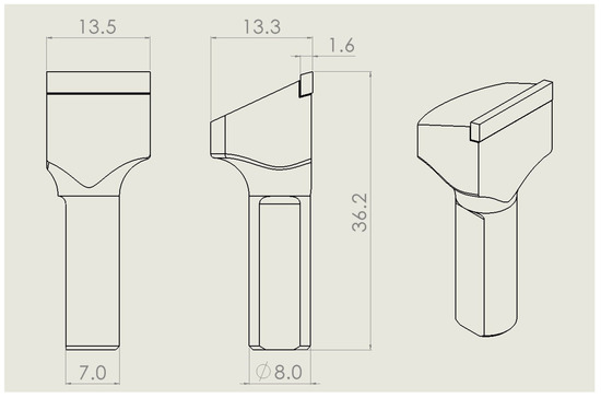
Figure 2.
Schematic representation of the geometry of the RJS specimens geometry. Dimensions in millimetres.
2.3. Experimental Procedures
Following the tool’s life cycle presented previously, a summary of the testing plan regarding each of the stages under analysis can be observed in Table 2.

Table 2.
Testing plan summary for the life-cycle analysis of the tools. Tool body materials defined as steel (St) and aluminium (Al).
The investigation first concentrated on the manufacturing phase of the tool life cycle (Stage 2). At this point a gravimetric study was performed in order to understand the fluid uptake characteristics of the EDM fluid. Due to the peculiar mass fluctuations, an FTIR spectrum analysis was employed to investigate the influence of the dielectric fluid on the adhesive. In the end, to determine how much damage this fluid uptake caused, shear strength tests were carried out using RJS specimens to compared the results obtained against those of the unaged condition. This last test was also undertaken in order to analyse the effect of the surface treatments on the joint’s strength.
In the following stage (3), another gravimetric analysis was carried out, but this time for the two fluids (water and cutting emulsion). The shear strength tests were also performed for these conditions.
For the maintenance stage (4) of the tool’s life cycle, the goal was to check whether the re-curing of only that bit which is in need of repair would have an influence on the other bonded connections. Otherwise, it could be necessary to replace the adhesive layer in all other cutting bits of the tool. Accordingly, the RJS specimens were submitted to several thermal curing cycles in order to assess this effect. Regarding the cleaning aspect of Stage 4, continuous and cyclic submersion approaches were adopted for each cleaning fluid tested, making use of shear strength tests.
Finally, it is important to mention that no fluid uptake research was performed for the cleaning fluids (petroleum oil and ultrasound fluid) since, in theory, these cleaning agents will only come into contact with the joint for a very limited period of time when compared with the other fluids. Furthermore, should these fluids be shown to be highly damaging at this stage, the logical recommendation should be that the tool should simple be fully repaired instead of simply resharpened.
Each of the used test types and their respective procedures are described in the following subsections.
2.3.1. Gravimetric Analysis
Prior to immersion in the fluids under study (water, dielectric fluid and cutting emulsion), the adhesive bulk plates were manually sanded with 800 grit sandpaper in order to remove any impurities from the surface. The plates were then fully dried in silica for two weeks at 70 °C to guarantee that the initial state of the adhesive contained no internal moisture. The mass of the dried bulk plates was measured before the specimens were immersed in the fluids. While submerged, the plates had no contact with each other or the container, being completely covered in the respective fluids, so that the area available for absorption was the same for all specimens. Each container was placed in a climatic chamber at the desired temperature and was periodically removed for measurements of the sample mass. The plates were dried with a paper towel every time they were removed from the fluid and their mass was measured on a microbalance with 0.1 mg of accuracy. The moisture uptake for each specimen (Mt) was calculated by Equation (1).
where mt is the mass of the bulk plate at each measurement and m0 is the initial mass of the dried plate [26]. For each fluid, four specimens were measured.
For a normal Fickian uptake, the measurements would be considered complete when the fluid content was stable, meaning that the adhesive plates were incapable of absorbing more fluid. However, as will be seen in a future section, the sorption behaviour of the adhesive is more compatible with a non-Fickian approach. Therefore, the measurements were stopped when it was possible to find a properly fitted curve, following non-Fickian diffusion equations.
It is also crucial to note that this analysis did not cover cleaning fluids such as petroleum oil and ultrasound fluid for a number of reasons. First off, since the ultrasonic fluid is a more damaging fluid, the damage aspect is more significant than the degradation component. Furthermore, compared with other fluids, such as water and cutting emulsion, the contact times with these cleaning fluids are several orders of magnitude shorter and do not represent a condition in which long term absorption data are valuable.
2.3.2. Fourier Transform Infrared Spectroscopy (FTIR)
Because of their unusual mass fluctuations, an FTIR spectra analysis was undertaken for the specimens submerged in dielectric fluid. FTIR allows for a determination of the extent of moisture ageing, as it highlights changes in the chemical composition of the material under study. If any material was transferred between the liquid and the immersed polymer, there would be a change in the spectrum, with an alteration of the intensity of absorption bands for the corresponding chemical groups. This analysis was performed on bulk plates aged for a month and a half and on the fluid in which they were immersed. Control samples of both adhesive bulk plates and dielectric fluid were also tested to allow for a term of comparison.
2.3.3. RJS Strength Degradation Analysis
The RJS specimens were used to determine the effect of several ageing conditions described below. The specimens were then shear tested and compared with their unaged counterparts, as a benchmark. For each condition, a minimum of three valid specimens were tested.
Ageing Due to Common Industrial Fluids
In order to simulate the saturation time of the adhesive joints for this portion of the analysis, RJS specimens were immersed in water and cutting emulsion for one month. Because, in the case of the milling tools under study, it is uncommon to undergo more than five/six sharpening cycles, two dielectric fluid exposure conditions were tested for each of the specimen materials, corresponding to the time of one tool sharpening cycle (200 min) and five sharpening cycles (1000 min). For each fluid, both steel and aluminium specimens were aged.
Ageing Due to Surface Coatings
To evaluate the effect of common industry surface coatings on the strength of the adhesive joint, a set of steel RJS specimens was subjected to oxidation and nickel-plating procedures. These treatments were applied by FREZITE®, following the same surface coatings used in current commercial milling tools. Oxidation and nickel-plating are treatments that subject the workpiece to chemical baths at high temperatures and, therefore, are expected to cause a severe degree of hygrothermal degradation of the adhesive joint.
Ageing Due to Tool Cleaning
To simulate tool cleaning, two procedures are defined, a continuous process reproducing long exposures and a cyclic process to reproduce multiple cleaning cycles. For the first case, the RJS specimens were once again continuously submerged, but in this case in petroleum oil and ultrasound fluid. After a given period of time, a group of specimens was taken out of the fluid and was subjected to shear strength testing. By observing how shear strength changes with immersion duration, it was possible to provide a more accurate estimate of the maximum time a tool should be in contact with the cleaning fluid.
Then, as mentioned previously, in order to evaluate the effect of cyclic exposure to the fluids, RJS specimens were immersed for a certain time span before being dried in the oven, while placed in silica, at 70 °C for 45 min. This was done to simulate cutting operations at an elevated temperature. This cycle was repeated six times to simulate the maximum number of sharpening cycles. By doing this, we can confirm how the tool works after being cleaned several times by obtaining the adhesive joint behaviour after a number of cleaning cycles.
The time spans of both the continuous and cyclic procedures were longer for the petroleum oil, since the ultrasound fluid is more damaging. Figure 3 displays the ageing plan for both fluids and presents the times spans used for each.
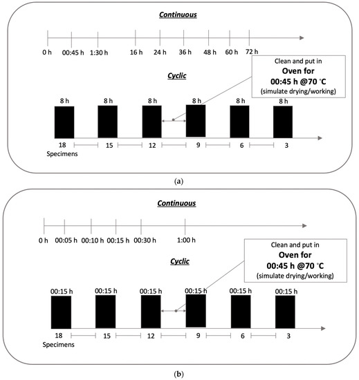
Figure 3.
Continuous and cyclic test plan for petroleum oil and ultrasound fluid. (a) Petroleum oil. (b) Ultrasound fluid.
Sandblasting was also considered, as it is a simple and effective method for removing initial residue from the tool. Four different time periods were applied to the RJS specimens—10, 35, 70, and 150 s. This allows for the determination of the maximum amount of exposure time for which this technique is practical.
Additionally, the data supplied by the manufacturer are shown in Table 3, showing adhesive ageing as a result of exposure to two types of fluids—petroleum-based fluids and ultrasound fluids. This was used as a benchmark against the results from the current tests.

Table 3.
Ageing guidelines for different mediums, based on the compression shear strength of aluminium single lap joints of aged specimens against unaged specimens. Obtained from the adhesive’s datasheet.
Ageing Due to Repair
To finalise the maintenance related degradation tests, RJS specimens were, once again, used to simulate the repair process used in the damaged milling tools, i.e., due to exposure to new thermal cycles.
Having stated that, the test plan conformed to the format shown in Figure 4.
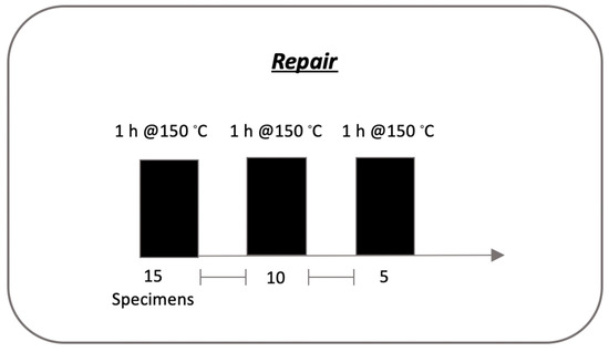
Figure 4.
Testing plan for the repair analysis.
Following this plan, after a cure cycle of one hour in the oven at 150 °C, five specimens were shear tested. This procedure was repeated three times, allowing us to estimate the joint’s strength after three repairs.
Additionally, another set of specimens was used to evaluate the shear strength after a full repair. In this operation, the cutting bit and the adhesive are fully removed from the tool and the bit is re-applied as if a new joint was being manufactured. This allows for the determination of the difference between a partial repair, a full repair process and a freshly made joint.
Shear Strength Tests
Following the degradation stage, all of the RJS specimens required testing to determine their shear strengths. These specimens were tested on a Gerling Automation® (Aspach, Germany) GLFP strength measuring unit, designed to test brazed connections on saw blade cutting bits. A specialised gig, custom designed to fix the specimens to the machine, was used. The equipment is manually operated and provides a reading for the maximum shear force applied to the cutting bit of the specimen by the press bolt. A comparison was drawn between the shear strength obtained for the aged and unaged specimens.
The apparatus used for this procedure can be observed in Figure 5.
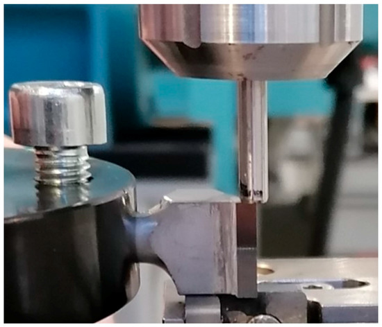
Figure 5.
Specimen shear testing setup.
2.3.4. Tool’s Dimensional Variation
These tools can be in contact with water or submerged in cutting emulsion for long periods of time, which might lead to excessive fluid absorption and swelling. Even if the joint strength is not significantly affected, swelling can alter the dimensions of the milling tool, possibly impacting the surface finish and uniformity of the workpiece. A testing setup was devised to assess this phenomenon, whereupon a steel prototype of the milling tool was immersed in cutting fluid for seven days at room temperature and then measured. This allowed us to compare the diameter of the tool before and after the immersion, which is a crucial geometrical parameter. Cutting fluid was chosen for this test since it promotes higher fluid uptake than water and, therefore, is the worst-case scenario for this issue.
The diameter measurements were made using a ZOLLER® (Pleidelsheim, Germany) redomatic measuring rig with corresponding software interface. The machine required thorough cleaning and calibration before usage, in order to eliminate measuring errors. The diameter was measured for every cutting bit and the initial and final diameter average values were compared.
3. Experimental Results and Discussion
This section presents the experimental results of this work, which can be seen in Figure 1, where they are organised in accordance with the various stages shown in the tool’s life cycle scheme. As a result, each of the four portions was independently examined in a chronological tool life cycle, ignoring Stage 1, since these results were procured to improve this component.
For the RJS shear strength test, a threshold was developed to better indicate the maximum advisable time that the joint could be in contact with the fluid. The adhesive in use has a shear strength (τf) of 41.6 MPa; thus, by adding a 0.75 factor—which means the maximum permitted decrease is 25%—it is possible to achieve a minimum threshold for the shear strength (τf) of 31.2 MPa. From this, the stress is obtained by multiplying this strength value with the area of the adhesive joint, which results in a minimum load for this geometry of 1.5 kN.
3.1. Stage 2—Production
Here the contact with EDM fluid and steel surface coatings is presented.
3.1.1. EDM Fluid—Gravimetric Analysis
The uptake values for the bulk plate specimens immersed in dielectric fluid are shown in Figure 6.
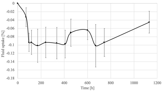
Figure 6.
Experimental results of the gravimetric analysis in dielectric fluid.
When compared with the behaviour of other fluids, the dielectric fluid shows an unusual evolution, the most notable characteristic being a negative fluid uptake; however, this variation is slight and in the order of 0.1%.
Because the uptake was unstable and there was weight loss in the bulk plates, no diffusion law could be approximated to the experimental results.
Fourier Transform Infrared Spectroscopy (FTIR)
In order to understand the evolution of the adhesive bulk plate samples on the dielectric fluid, an FTIR analysis was carried out on four samples: two unaged bulk plate samples and two bulk plate samples aged in dielectric fluid. The FTIR spectra obtained for the bulk plate samples can be seen in Figure 7.
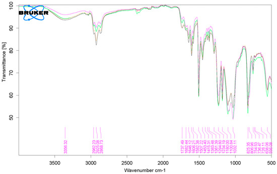
Figure 7.
FTIR spectra obtained for bulk plate specimens, showing chemical changes in the alkane region between the control/unaged (green and pink lines) and aged samples (black and yellow lines).
When comparing both obtained spectra, it is possible to see that the chemical profiles of both samples are very similar, with the only noticeable variation occurring in the region of 2840−3000 cm−1. From the infrared spectroscopy tables, an increase in this frequency region corresponds with an absorption of alkanes, which is a common chemical compound found in machining and lubricating oils. From this analysis, one can conclude that there could have been a slight variation in the composition of the polymer most likely in the outer layer of the specimen, caused by the gravimetric ageing.
Nonetheless, the reasoning behind this behaviour is still highly speculative. In general, when looking at the order of magnitude of the values of uptake, the high standard deviation, the nearly unseen change in the FTIR spectra from unaged to aged samples and the possible experimental variability, the main conclusion is that the EDM fluid does not affect the adhesive by itself.
3.1.2. EDM Fluid—RJS Ageing
For each material, the specimens immersed in the dielectric fluid underwent two different ageing conditions corresponding to one sharpening cycle and five sharpening cycles. The maximum shear strength values for aluminium and steel specimens are presented in Figure 8a,b, respectively.
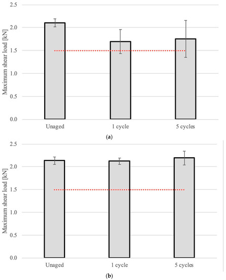
Figure 8.
Maximum shear strength of RJS specimens, unaged and aged (in dielectric fluid) for the duration of one and five sharpening cycles. The red dotted line represents the threshold value for the RJS specimen’s minimum allowed joint strength (1.5 kN). (a) Aluminium RJS specimens. (b) Steel RJS specimens.
The dielectric fluid had little to no effect on the shear strength of the joints for steel specimens, and a comparatively small decrease in shear load for aluminium specimens. This coincides with the behaviour observed in the gravimetric analysis, meaning that there was nearly no ingress of fluid on the adhesive and that the adhesive itself was not damaged.
The reduction in strength in the aluminium specimens was attributed to the joint’s interfacial properties, which usually are worse for raw aluminium in comparison with steel. Therefore, since the interface also allows for fluid sorption, the aluminium joints were damaged at the interface, resulting in a strength decrease under the aged conditions near the defined threshold developed at the beginning of Section 3.
The low influence of this hydrocarbon-based fluid on the mechanical properties of the joint is in accordance with that which is reported by the manufacturer of the adhesive, as shown in Table 3.
3.1.3. Surface Coatings—RJS Ageing
Steel RJS specimens were coated through oxidation and nickel-plating. The results of the shear tests of coated specimens can be seen in Figure 9.
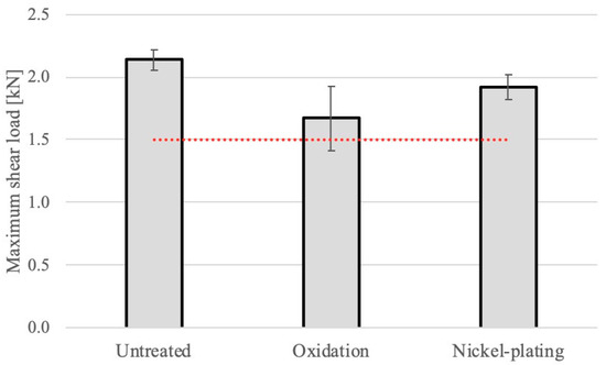
Figure 9.
Maximum shear strength of steel RJS specimens coated by oxidation and nickel-plating, compared with reference untreated specimens. The red dotted line represents the threshold value for the RJS specimen’s minimum allowed joint strength (1.5 kN).
As expected, the corrosive chemical baths required for the surface coating of steel led to a decrease of the shear strength of the bonded connection. Oxidation is the process that most affects the adhesive, resulting in a 22% loss of shear strength. Overall, the final mean values were above the threshold established. Nonetheless, the reduction in strength could be detrimental in the future of the tool considering the other stages of the tool’s life.
3.2. Stage 3—Work Life
In this stage, contacts with ambient moisture (water) and cutting emulsions are described.
3.2.1. Water—Gravimetric Analysis
The average experimental value for the water uptake of the adhesive bulk plate samples can be seen in Figure 10.
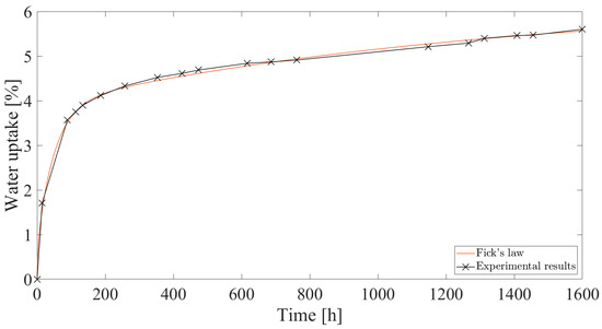
Figure 10.
Dual-Fickian numerical model curve and experimental results for the gravimetric analysis in water.
Since the experimental values of water uptake did not stabilize, as can be seen by the slope of the curve, the uptake cannot be described by normal Fickian diffusion. Therefore, a dual-Fickian model was considered in order to best fit the experimental data. The rule that describes the Berens and Hopfenberg model is given by [20] Equation (2).
where t is the time starting from the immersion of the specimens and l is the thickness of the plates. A Matlab script was developed in order to obtain the best fitting values for the coefficient of diffusion, D, infinite water uptake in the unrelaxed polymer, MD∞, infinite uptake related to the relaxation process, MR∞,i and relaxation rate constant, Ωi, for five relaxation processes, i. The literature indicates that two relaxation terms constitute the minimum required values of i that provide a good fit to the experimental data [16]. The values determined for this analysis are given in Table 4.

Table 4.
Water uptake properties.
Using these values, the following curve was obtained to fit the experimental values. A perfect fit was attained, confirming that a dual-Fickian phenomenon characterises this adhesive.
3.2.2. Cutting Fluid—Gravimetric Analysis
The same analysis was performed for the cutting fluid, with the experimental results shown in Figure 11.
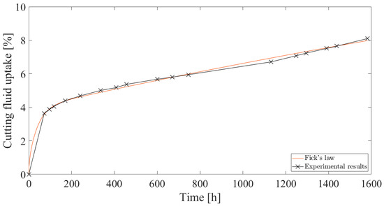
Figure 11.
Dual-Fickian numerical model curve and experimental results for the gravimetric analysis in cutting fluid.
A comparison can be drawn between this fluid and water, observing that ageing in cutting fluid results in a greater fluid uptake. This fluid also failed to arrive on stable values of uptake and, therefore, was approximated using the same dual-Fickian model as before. The diffusion and relaxation properties obtained for the uptake in this fluid are presented in Table 5.

Table 5.
Cutting fluid uptake properties.
Comparing the diffusion and relaxation components of the uptake model of each fluid, it is clear that the main difference between them is the relaxation stage. There is a similar initial uptake for both fluids until the 200-h mark is reached, but with a very different relaxation phenomenon, which results in a much higher final sorption value for the cutting fluid.
As such, since this fluid is mostly water-based, it is natural to encounter a similar diffusion phenomenon. However, the lubricating agent (emulsion of 7 to 9%) present in the cutting fluid does seem to influence the relaxation process of the polymeric chains.
The numerical approximation of the experimental values produced the curve shown in Figure 11. Once more, there was good agreement, showing that a dual-Fickian model describes well the sorption behaviour of this adhesive.
3.2.3. Water—RJS Ageing
Aluminium and steel RJS specimens were immersed in water until saturation and subsequently tested in shear loading until failure. The maximum load values are shown in Figure 12 and compared with the reference load strength obtained by Gomes et al. [14] for oven cured specimens.
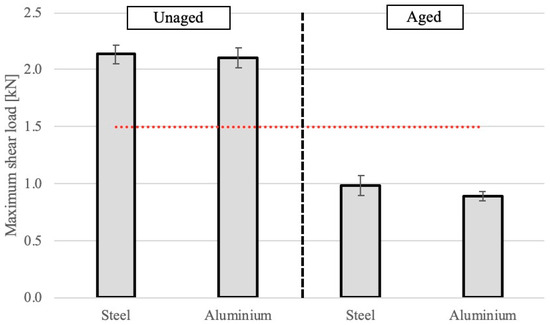
Figure 12.
Maximum shear strength of RJS specimens in unaged and aged (in water) conditions. The red dotted line represents the threshold value for the RJS specimen’s minimum allowed joint strength (1.5 kN).
There is a noticeable drop in joint strength after the specimens were aged in water. The failure mode for the aged samples was mostly adhesive, as opposed to cohesive failure for the unaged specimens, which indicates the ingress of water into the interface, as expected. The aged condition drooped below the defined threshold.
3.2.4. Cutting Fluid—RJS Ageing
RJS specimens of both materials were aged in cutting fluid until saturation and then subjected to strength testing. The load values obtained can be seen in Figure 13.
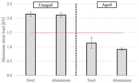
Figure 13.
Maximum shear strength of RJS specimens in unaged and aged (in cutting emulsion) conditions. The red dotted line represents the threshold value for the RJS specimen’s minimum allowed joint strength (1.5 kN).
For cutting fluid, a behaviour similar to the water-aged specimens was observed. The shear load was nearly halved for both materials and it was possible to observe adhesive failure. Similar values were obtained in terms of loss of strength, though this fluid proved more severe in terms of uptake in the adhesive. However, since they presented mostly adhesive failure, the weaker link in the joint was the interface. As such, the degree of damage to the interface is similar for both aged conditions.
Both fluids were found to be more damaging to the aluminium joints, with a drop of around 10 to 15% in the failure load and, once more, the aged condition was found to drop below the defined strength threshold.
3.2.5. Cutting Fluid-Tool’s Dimensional Variation
The steel tool prototype was loaded onto the machine and each bit was aligned with the measuring rig while the software recorded the diameter measurements, measurements and dimensional variations are presented in Table 6.

Table 6.
Dimensional variation measurements.
The initial diameter (Di) was measured at 99.993 mm.
The tool was then immersed in cutting fluid at room temperature for a period of seven days. This scenario is much more intensive than the service conditions of the tool. After the seven days elapsed, the tool was remounted on the measuring device and the final diameter (Df) was recorded at 100.005 mm.
The variation in diameter (ΔD) is 0.012 mm, which corresponds to 0.01% of the initial diameter. To assess the effect of this variation in the dimensions of the workpiece, one must consider the radial variation (Δr), corresponding to half of ΔD. This results in a Δr of value 0.0006 mm, which is negligible for the finish quality expected from wood milling tools.
3.3. Stage 4—Maintenance
This subsection presents the results where contact is made with cleaning procedures using petroleum oil, ultrasound fluid, and sandblast, and the results of the repair tests recurring to thermal cycles.
3.3.1. Petroleum Oil—RJS Ageing
Continuous Cleaning
In this test, aluminium RJS specimens, were immersed in petroleum oil for a given period of time and subsequently tested in shear loading until failure. The aluminium specimens correspond to the worst-case scenario in this test. The maximum load values are shown in Figure 14, for which the 0 h condition represents the initial, unaged condition. Due to the fact that multiple batches of specimens were manufactured for all the tests, the initial value (0 h) may vary slightly.
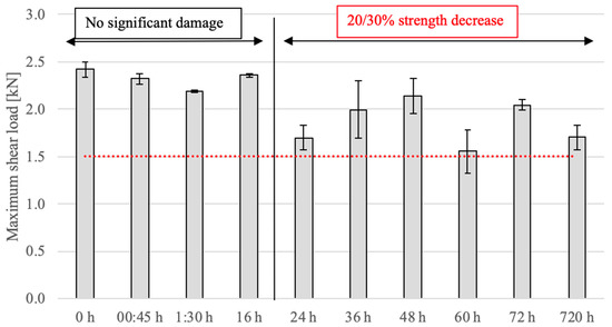
Figure 14.
Maximum shear strength of RJS specimens continuously immersed in petroleum oil. The red dotted line represents the threshold value for the RJS specimen’s minimum allowed joint strength (1.5 kN).
From the presented data, there is no distinct pattern with regard to the way in which petroleum oil affects the joint’s maximum strength, with no clear correlation between the amount of time the joint spends submerged in the fluid and strength loss. This variability, defined by both the oscillating mean values and high standard deviations, is explained by the small scale of the adhesive joints used, where small defects in the joint can result in significant reductions in strength. In this case, this is also related to higher fluid uptake in the interface and/or defects of the joint.
Having said that, and taking into consideration the established threshold, a maximum of sixteen continuous hours of immersion in petroleum oil can be defined as a practical limit. This allows us to preserve the performance of the bonded joint, with a 20 to 30% reduction in the maximum shear strength.
These findings are backed by the information depicted in Table 3 for 100 h. Typically, a wide range of oils lead to a 15 to 20% decrease in strength. In the case of this study, the decrease was slightly higher, which is somewhat expected, since the bonded area of the RJS specimens is extremely small and any diffusion through the interface will lead to significant changes in joint performance.
Despite this, the long-term results are in line with what was anticipated by the 500 h and 1000 h conditions of the aforementioned oils, where the damaging effect stabilised. This is also the case for this fluid, where after one month (720 h) it maintained an approximately 20% decrease.
Cyclic Cleaning
For this scenario, aluminium RJS specimens were once again submerged in petroleum oil, but in this case for a pre-determined period of time—8 h—before being dried in silica for 45 min at 70 °C. These procedures comprise a cycle and after each cycle three specimens were tested. The maximum load values are shown in Figure 15, in which the 0 h condition represents the initial condition.
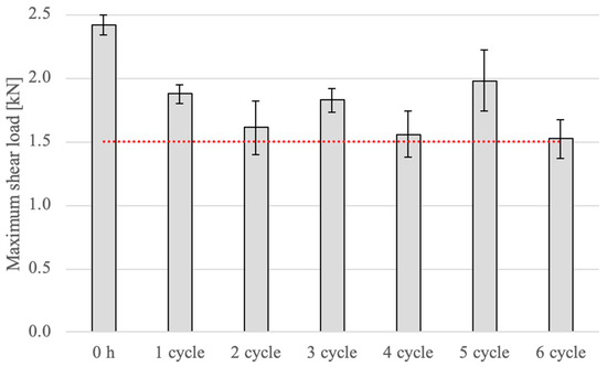
Figure 15.
Maximum shear strength of RJS specimens immersed in petroleum oil following a cyclic pattern. The red dotted line represents the threshold value for the RJS specimen’s minimum allowed joint strength (1.5 kN).
When compared with the initial condition, there is a clear drop in strength for all cycles. Although some scatter exists, it is possible to say that, on average, there is a trend for more cycles leading to slightly worse maximum shear strength. In the end, the six cleaning cycles can be implemented in practice as the drop in strength does not reach critical values, and the adhesive joint would still hold up under working conditions, presenting around 75% of the original strength.
3.3.2. Ultrasound Fluid—RJS Ageing
Continuous Cleaning
An approach identical to that developed for the petroleum oil was used in this section. Aluminium RJS specimens were repeatedly tested in a shear loading until failure was reached, following submersion in an ultrasound fluid mixture for a number of continuous time periods.
Figure 16, where the 0 h condition indicates the initial condition, displays the maximum load levels.
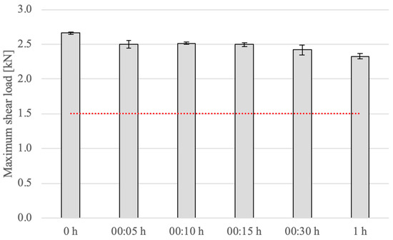
Figure 16.
Maximum shear strength of RJS specimens continuously immersed in an ultrasound mixture. The red dotted line represents the threshold value for the RJS specimen’s minimum allowed joint strength (1.5 kN).
Taking into account the results of this test, this cleaning option leads to more consistent behaviour, where a decline in strength with time is evident.
Nevertheless, the maximum decrease for this test is just 12.5%, which is not as high as that observed for petroleum oil cleaning. Therefore, it becomes evident that this fluid is in fact more adequate for cleaning aluminium bonded tools.
Cyclic Cleaning
Once again, the same testing approach used for petroleum oil was applied. The pre-determined period of time was 15 min, as this is the typical average value used industrially for ultrasound cleaning. After each cycle, the specimens are dried in silica for 45 min at 70°C. These procedures comprise a cycle and after each cycle three specimens were tested.
The maximum shear strength values are depicted in Figure 17, 0 h defined the initial condition.
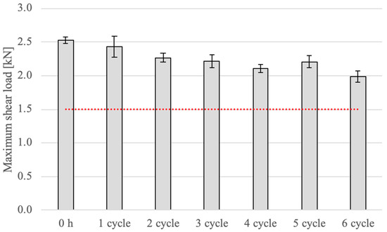
Figure 17.
Maximum shear strength of RJS specimens immersed in an ultrasound mixture following a cyclic pattern. The red dotted line represents the threshold value for the RJS specimen’s minimum allowed joint strength (1.5 kN).
Unlike that which was was verified for the petroleum oil, the cleaning fluid shows well-defined behaviour, showing a gradual decrease in strength. These results also show that the ultrasound cleaning is a suitable option for cleaning bonded joint milling tools, leading only to a small decrease in shear strength and enabling fast cleaning times.
Looking at the data present in Table 3, which shows that for common fluids used in ultrasound cleaning, such as benzine, water/glycol and ethanol, a similar gradual decrease in strength is presented from 100 h to 1000 h. When compared with petroleum oil, the main drawback of this cleaning option would be a larger decrease over longer exposure times.
3.3.3. Sandblasting—RJS Ageing
To finalise the cleaning tests, a mechanical cleaning alternative was analysed to evaluate its usability. The failure load values are shown in Figure 18, in which the 0 s condition represents the initial condition.
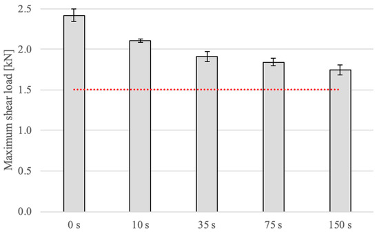
Figure 18.
Maximum shear strength of RJS specimens subjected to a jet blast of sand particles. The red dotted line represents the threshold value for the RJS specimen’s minimum allowed joint strength (1.5 kN).
A clear behavioural pattern can be observed—higher exposure times leading to a larger drop in the maximum shear strength—when compared against the initial condition. However, though the strength did not decrease below the stabilised threshold, this cleaning option would not be the best choice since it removes the adhesive fillet—present in the joint to protect and improve its strength—after about 30 s, which would hinder its long-term usability.
3.3.4. Tool Repair—RJS Ageing
Though aluminium has worse adhesion characteristics, making it the theoretical worst-case scenario, both aluminium and steel specimens were tested, in order to consider the effect of the heat cycles in the interface properties of the joint.
The maximum load values for the aluminium specimens are shown in Figure 19, where 1 × 150 °C defines the load value after the initial cure cycle, used solely to manufacture the specimen.
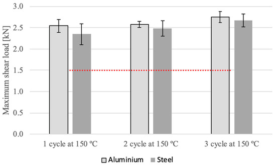
Figure 19.
Maximum shear strength of RJS specimens subjected to multiple repair cycles. The red dotted line represents the threshold value for the RJS specimen’s minimum allowed joint strength (1.5 kN).
The findings show that there were no problems with the repair bonded joint milling tools, as there is no loss in shear strength. In fact, after several repair cycles the tool strength appears to have slightly improved. This phenomenon could have resulted from a post-curing effect of the adhesive.
4. Conclusions
This study had the goal of analysing a milling tool’s life cycle and to thus assess how the degradation processes to which an adhesively bonded milling tool might be exposed influence the joint performance. This adhesive bonding process was previously studied and characterised by Correia et al. and Gomes et al., making this work a new stepping stone in the study of this manufacturing process, one that is geared towards the long-term degradation experienced during a tool’s life cycle. From this work, the following conclusions can be drawn:
- In the production stage, the dielectric fluid showed no signs of uptake into the adhesive plates and, therefore, was subjected to an FTIR analysis, where no significant changes were observed between the control and the aged samples;
- The strength tests revealed that the ageing in this fluid has no effect on the strength of the adhesive joint when the adherent material is steel. However, there is some decrease in shear load capacity for aluminium specimens;
- Applying surface coatings to steel tools has a negative effect on the strength of the bond. Since the chemical treatments involve corrosive environments and high temperatures and are, oftentimes, undertaken for uncertain and unquantifiable periods of time—until the desired aesthetic finish is observed—it is very difficult to assess the true effects of the process. From a productive standpoint, these coatings should be avoided, and different surface finishes must be chosen;
- During a tool’s usage, fluids such as water (ambient moisture, etc.) and cutting emulsion (metal-cutting tools) are in constant contact with the joint. Having said that, the gravimetric analysis led to the understanding that both water and cutting emulsion have a high rate of diffusion into the adhesive, through a relaxation-controlled process;
- Nevertheless, the cutting emulsion causes much higher uptake since its relaxation phenomenon is more severe. During strength testing it was determined that both fluids reduced the shear load withstood by the joint by more than 50%;
- Maintenance activities performed on the tool also raised concerns regarding joint degradation. However, the petroleum oil analysis allowed us to understand that the joint is still functional after six maintenance cycles;
- A maximum submergence time of sixteen hours was obtained for the petroleum oil, as more time than this would lead to a 20–30% decrease in the joint’s shear strength;
- The ultrasound cleaning mixture produced very acceptable results, and was identified as the best alternative to clean bonded joint milling tools, as after six maintenance cycles the strength decrease was only around 10%;
- In general, these tools should not be cleaned with sandblasting, as, though the shear strength decrease was not critical, this procedure eliminates the beneficial adhesive fillet. Nevertheless, a maximum application of 10 s should be used and only if it is absolutely necessary for the removal of hard residue;
- The repairability tests revealed that it is possible to repair just the bits that were broken during use, as the remaining cutting bits had no adverse effects on the multiple curing cycles;
- The concerns over the dimensional variation of the adhesive joints proved to be unwarranted, since the rate of dimensional fluctuation was too small to have an effect on the quality and accuracy of the cut.
Finally, it is important to consider that these specimens were tested in isolation, and real-life conditions present a summation of different effects when all of these conditions are considered at the same time. Nonetheless, this study allowed us to precisely characterise the behaviour of bonded tools under diverse degradation conditions, and thus establish quality assurance guidelines for the manufacturing, storage, work and maintenance stages in the life of a bonded milling tool.
Author Contributions
Conceptualization, R.J.C.C., E.A.S.M. and L.F.M.d.S.; Investigation, R.J.F.d.S. and P.N.G.; Resources, P.J.C.d.N. and W.P.A.; Writing—original draft, R.J.F.d.S. and P.N.G.; Writing—review & editing, D.S.C., R.J.C.C. and E.A.S.M.; Supervision, D.S.C., R.J.C.C., E.A.S.M., P.J.C.d.N., W.P.A. and L.F.M.d.S.; Project administration, L.F.M.d.S. All authors have read and agreed to the published version of the manuscript.
Funding
This research received no external funding.
Institutional Review Board Statement
Not applicable.
Informed Consent Statement
Not applicable.
Data Availability Statement
The data presented in this study are available on request from the corresponding author.
Conflicts of Interest
The authors declare no conflict of interest.
References
- Darwish, S.; Davies, R. Investigation of the heat flow through bonded and brazed metal cutting tools. Int. J. Mach. Tools Manuf. 1989, 29, 229–237. [Google Scholar] [CrossRef]
- Darwish, S.; Niazi, A.; Ghaneya, A. Phase stability of duralumin machined with bonded and brazed carbide tools. Int. J. Mach. Tools Manuf. 1992, 32, 593–600. [Google Scholar] [CrossRef]
- Younis, M.A. Mechanical and Thermal Stresses in Clamped, Brazed, and Bonded Carbide Tools. J. Eng. Ind. 1992, 114, 377–385. [Google Scholar] [CrossRef]
- Al-Samhan, A.M. Thermal-stresses in carbide-tip bonded face milling cutters. J. King Saud Univ.-Eng. Sci. 2012, 24, 85–94. [Google Scholar] [CrossRef]
- Darwish, S. Effect of tool bit insert-holder assembly on the quality of machined workpieces. J. Mater. Process. Technol. 2000, 105, 230–236. [Google Scholar] [CrossRef]
- Darwish, S. Machining of difficult-to-cut materials with bonded tools. Int. J. Adhes. Adhes. 2000, 20, 279–289. [Google Scholar] [CrossRef]
- Jachak, S.; Giri, J.; Awari, G.K.; Bonde, A.S. Surface finish generated in turning of medium carbon steel parts using conventional and adhesive bonded tools. Mater. Today Proc. 2021, 43, 2882–2887. [Google Scholar] [CrossRef]
- Kilik, R.; Davies, R. Mechanical properties of adhesive filled with metal powders. Int. J. Adhes. Adhes. 1989, 9, 224–228. [Google Scholar] [CrossRef]
- Davies, R.; Darwish, S. Temperature distribution of bonded tools having atomized copper powder mixed with adhesive. Int. J. Mach. Tools Manuf. 1991, 31, 617–623. [Google Scholar] [CrossRef]
- Darwish, S.; Niazi, A.; Ghania, A.; Kassem, M.E. Improving the electrical properties of structural epoxy resin adhesives. Int. J. Adhes. Adhes. 1991, 11, 37–42. [Google Scholar] [CrossRef]
- Correia, D.S.; Carbas, R.J.C.; Marques, E.A.S.; das Neves, P.J.C.; da Silva, L.F.M. Experimental study on aluminium to tungsten carbide/polycrystalline diamond (wc/pcd) adhesive bonding for milling tools. Int. J. Adhes. Adhes. 2022, 114, 103121. [Google Scholar] [CrossRef]
- Correia, D.S.; Marques, E.A.S.; Carbas, R.J.C.; das Neves, P.J.C.; da Silva, L.F.M. Numerical optimisation of bonded joints for the manufacture of edge milling tools. Eng. Fail. Anal. 2022, 134, 106012. [Google Scholar] [CrossRef]
- Correia, D.S.; Marques, E.A.S.; Carbas, R.J.C.; das Neves, P.J.C.; da Silva, L.F.M. Practical implementation and validation of a novel process for manufacturing milling tools using adhesive bonding. In Proceedings of the 2nd International Conference on Advanced Joining Processes (AJP 2021): Selected Contributions of AJP 2021, Sintra, Portugal, 21–22 October 2021; pp. 181–195. [Google Scholar]
- Gomes, P.N.; Correia, D.S.; Marques, E.A.S.; Carbas, R.J.C.; das Neves, P.J.C.; Afonso, W.P.; da Silva, L.F.M. Optimization of curing processes for the manufacturing of adhesively bonded milling tools. Under Rev. Int. J. Adhes. Adhes. 2022, 43, 2882–2887. [Google Scholar]
- Barbosa, A.Q.; da Silva, L.F.M.; Öchsner, A. Hygrothermal aging of an adhesive reinforced with microparticles of cork. J. Adhes. Sci. Technol. 2015, 29, 1714–1732. [Google Scholar] [CrossRef]
- da Silva, L.F.M.; Öchsner, A.; Adams, R.D. Handbook of Adhesion Technology; Springer: Berlin/Heidelberg, Germany, 2018. [Google Scholar]
- Gledhill, R.A.; Kinloch, A.J. Environmental failure of structural adhesive joints. J. Adhes. 1974, 6, 315–330. [Google Scholar] [CrossRef]
- Gledhill, R.A.; Kinloch, A.J.; Shaw, S.J. A model for predicting joint durability. J. Adhes. 1980, 11, 3–15. [Google Scholar] [CrossRef]
- Loh, W.K.; Crocombe, A.D.; Abdel Wahab, M.M.; Ashcroft, I.A. Modelling anomalous moisture uptake, swelling and thermal characteristics of a rubber toughened epoxy adhesive. Int. J. Adhes. Adhes. 2005, 25, 1–12. [Google Scholar] [CrossRef]
- Berens, A.R.; Hopfenberg, H.B. Diffusion and relaxation in glassy polymer powders: 2. separation of diffusion and relaxation parameters. Polymer 1978, 19, 489–496. [Google Scholar] [CrossRef]
- Ocaña, R.; Arenas, J.M.; Alía, C.; Narbón, J.J. Evaluation of degradation of structural adhesive joints in functional automotive applications. Procedia Eng. 2015, 132, 716–723. [Google Scholar] [CrossRef]
- Sousa, J.M.; Correia, J.R.; Firmo, J.P.; Cabral-Fonseca, S.; Gonilha, J. Effects of thermal cycles on adhesively bonded joints between pultruded gfrp adherends. Compos. Struct. 2018, 202, 518–529. [Google Scholar] [CrossRef]
- Humfeld, G.R., Jr.; Dillard, D.A. Residual stress development in adhesive joints subjected to thermal cycling. J. Adhes. 1998, 65, 277–306. [Google Scholar] [CrossRef]
- Costa, M.; Viana, G.; Da Silva, L.F.M.; Campilho, R.D.S.G. Environmental effect on the fatigue degradation of adhesive joints: A review. J. Adhes. 2017, 93, 127–146. [Google Scholar] [CrossRef]
- ISO 294-3:2020; Plastics—Injection Moulding of Test Specimens of Thermoplastic Materials—Part 3: Small Plates. International Organization for Standardization: London, UK, 2020.
- Borges, C.S.P.; Akhavan-Safar, A.; Marques, E.A.S.; Carbas, R.J.C.; Ueffing, C.; Weißgraeber, P.; da Silva, L.F.M. Effect of water ingress on the mechanical and chemical properties of polybutylene terephthalate reinforced with glass fibers. Materials 2021, 14, 1261. [Google Scholar] [CrossRef] [PubMed]
Disclaimer/Publisher’s Note: The statements, opinions and data contained in all publications are solely those of the individual author(s) and contributor(s) and not of MDPI and/or the editor(s). MDPI and/or the editor(s) disclaim responsibility for any injury to people or property resulting from any ideas, methods, instructions or products referred to in the content. |
© 2023 by the authors. Licensee MDPI, Basel, Switzerland. This article is an open access article distributed under the terms and conditions of the Creative Commons Attribution (CC BY) license (https://creativecommons.org/licenses/by/4.0/).