Abstract
The increasing demand for container transportation makes it necessary to equip the wagon fleet with appropriate flatcars in good technical condition. The study deals with the determination of the strength of the flatcar during shunting impacts using the finite element method. The flatcar model 13-401 modernized with fixed fittings for securing containers on the frame was used as a prototype. The authors determined the fields of the maximum equivalent stresses in the bearing structure of a flatcar. The strength calculation was made in SolidWorks Simulation. It was found that, during a shunting collision, the maximum equivalent stresses to the flatcar were about 418 MPa and they were concentrated in the fixed fittings. The strength was also studied using the method of electric strain gauging. The research included different impact speeds. The test results showed that the maximum difference between the stresses obtained theoretically and experimentally was 17.0%. The strength model of the flatcar was tested using the Fisher criterion. The study demonstrated that the damage to the bearing structure of the flatcar and containers could be reduced when applying an improved interaction diagram.
1. Introduction
The efficiency of freight transportation along European transport corridors can be improved by means of innovative and effective rolling stock [1,2,3,4,5,6,7,8,9,10,11,12,13,14,15,16,17,18,19]. In international freight transportation, the flatcar is most vulnerable and susceptible to damage. This is due to the fact that flatcars are used to transport removable transport units, in particular, containers, tank containers, swap bodies, etc.
It is to be noted that one of the most damaged elements of the flatcar used for lashing containers is the fixed fitting. Most often, fixed fittings get damaged due to shunting collisions because of the presence of technological gaps between them and container fittings. This includes cracks, deformations, distortions, and others in container fittings and fixed fittings. Therefore, there is a need for unscheduled repairs and additional repair costs.
It is important to note that damage to fixed fitting during a shunting collision may result in internal defects, which, under operating conditions (jerking, compression, etc.), may cause the fixed fittings to break. Such a situation when a container is transported in a train is fraught with traffic safety issues and may cause the risk of derailment. Moreover, it can result in damage to the container and the freight inside it, environmental problems in the case of dangerous goods, etc.
This can be solved by determining the load of the flatcar during a shunting collision with the subsequent formulation of appropriate recommendations for keeping the bearing structure in good operating condition [1,2,3,4,5,6,7,8,9,10,11,12,13,14,15,16,17,18,19].
The purpose of the article is to study experimentally the strength of the bearing structure of a flatcar during a shunting collision. The tasks of the study are as follows:
- –
- To theoretically determine the strength of the flatcar;
- –
- To experimentally determine the strength of the flatcar;
- –
- To verify the strength model of the flatcar.
2. Analysis of Recent Studies and Publications
The strength indicators of the model T11 tank container placed on the flatcar during a shunting collision were determined by Makeev and Builenkov [4]. The results of the theoretical studies were confirmed by experiments conducted using the method of electrical strain gauging. The authors identified the most loaded structural areas and explained why the stresses were concentrated in those areas. However, they considered only the load of the tank container and did not investigate the strength of the flatcar.
The impact load of the vehicle was determined by Zamecnik and Jagelcak [5]. The authors used the acceleration as an experimental variable and a component of the dynamic load. The calculation was carried by means of mathematical modelling. The second-order differential equations were solved using the Lagrange method.
A unified concept of impact strength to optimize the body the rolling stock unit was considered by Mrzyglod and Kuczek [6]. It was represented as a rigid frame structure. The optimization problem was reduced to minimizing the body weight, taking into account the stress restrictions. The calculation was carried out with the finite element method, and the results obtained confirmed the feasibility of the proposed structural solutions. However, in the papers under consideration, the authors made only the theoretical determination of the strength of vehicles though using modern engineering software.
The dynamics of the rolling stock using an experimental laboratory car moving along complex track sections were investigated by Ermolenko and Zheleznyak [7]. The car had special equipment for recording the main dynamic indicators. Some measures for safe operation of rolling stock were proposed. The influence of track irregularities on the dynamic indicators of rolling stock was investigated. The effects of longitudinal forces acting on the load-bearing structure under operating conditions were also taken into consideration.
The peculiarities of the running strength and dynamic tests of the flatcar model 13-9975 were described by Chepurnoy et al. [8]. It was taken into account that the flatcar was loaded with 20- and 40-foot containers. The authors determined the dynamic indicators of the flatcar under the main operating load conditions and took into account mainly the loads acting on the flatcar being part of the train.
It is important to note that these studies do not present the results of determining the strength of the bearing structure of the rail car under a shunting collision, though it causes the highest load on the bearing structure in operation.
The study of the fatigue strength of the open wagon body was carried out by Zhong et al. [9] and Yuan et al. [10]. The open wagon model C80B, built in China, was chosen as a prototype. The calculation was carried out using the finite element method. The assumptions and limitations of this calculation are given. The results of the study demonstrated that the method of predicting the fatigue strength of the body based on dynamic modelling is possible. At the same time, this study did not include the case of a shunting collision of the car in operation.
The strength calculation of the wagon was carried out by Yoon [11]. The author considered only main design forces acting on the wagon operating on mainline tracks. Numerical values of these forces were selected according to the normative technical documentation. The accepted design diagram of the wagon body was substantiated. Moreover, the publication gives the analysis of the results obtained. It is important to say that the authors of [10,11] did not conduct experimental research of the strength of the wagon body. This would make it possible to verify the results obtained theoretically.
Vatulia et al. [12] calculated the loading of the flatcar with containers including the elastic–friction interaction between container fittings and fixed fittings. They proved that elastic interaction between the flatcar and the container decreased the dynamic loading in comparison with that of the standard diagram of interaction by 18%. However, they did not determine the load of the flatcar loaded with containers at the typical diagram of interaction.
Of scientific value is the determination of dynamic load of the flatcar carried out by Lovskaya and Ryibin [13]. The authors studied two loading diagrams for the flatcar: with displacements of the container relative to the frame during a shunting collision and without them. They determined how the displacements of the container affected the dynamic load of the container structure and the flatcar. However, no theoretical research was conducted, and the models were only verified by comparing the results of mathematical and computer modelling.
Nikitchenko et al. [14] carried out mathematical modelling of the load on the flatcar loaded with containers. The authors proposed a mathematical model that included the displacements of the containers relative to the frame during a collision and determined the acceleration values. This model included the longitudinal load of the flatcar with containers. Based on the results of the calculations, it was concluded that the accelerations acting on the flatcar with containers, if taking into account their compliance, were higher than normative values.
The study into the load of the flatcar with containers was carried out by Bogomaz et al. [15]. The interaction between the containers and the flatcar was simulated by means of elastic–dissipative connection at a longitudinal load of 2.2–2.8 MN applied by means of a hammer car. The model included three levels of freedom for the containers: bouncing and galloping oscillations as well as longitudinal displacements. The authors took into account the effect of the gap between a fixed fitting of the flatcar and a container fitting on their dynamic load. The study also presents the dependency between the impact from the longitudinal force and the acceleration to the flatcar and containers.
However, these studies have no experimental verification of the results obtained.
Chlus and Krason [16,17] calculated the strength of the flatcar equipped with the rotating frame, where the flatcar was loaded with containers. The authors studied the main load diagrams for the flatcar frame. The calculation was completed with Ansis software using the finite element method. The strength results as well as the analysis of the stress distribution fields in the load-bearing structure of the flatcar are presented. However, the theoretical strength calculation was not verified experimentally.
The special features of a nontrivial flatcar structure with an adjustable length of the frame are described in [18]. The flatcar frame consisted of separate structural blocks that were adjustable to the freight transported in length. That is, the structure was telescopic; the strength indicators of the operating modes were taken into account. Such a flatcar can be adapted to the transportation of containers. However, the authors did not describe the special features of the tests on the flatcar at operating modes.
Fomin et al. [19] investigated the load of wagons, including flatcars with the expired normative service life. They also studied the possibility of extending the service life. The publication presents the results of determining the dynamics and strength of the flatcar by means of mathematical modelling in which the longitudinal and vertical load of the bearing structure of the flatcar was taken into account. The results obtained were integrated into the strength calculation of the bearing structure. However, the results were not verified experimentally.
The review of literature sources makes it possible to conclude that the issue of experimental determination of the strength of the flatcar at the standard diagram of interaction between the fixed fitting and container fitting during a shunting collision has yet to be studied. Therefore, further research in the field is required.
3. Theoretical Determination of the Strength of the Flatcar
The strength of the flatcar loaded with containers during a shunting collision was studied with the FEM in SolidWorks Simulation (France) [20,21,22]. The model 13-401M flatcar built by the Dniprovagonmash Car Building Plant was chosen as a base model. The frame of the flatcar was of welded construction. The main bearing beam of the frame was the center sill. It consisted of two I-beams, which were shaped to resemble a beam of equal bending resistance. The main longitudinal beams also consisted of I-beams of variable length and height. The center sill and the main longitudinal beams were connected by two box-section end beams (bent angle and sheet), two closed box-section pivot beams, and rolled I-beams.
The end beam had a handrail for the stacker and a socket, which was molded together with the front stops of the car coupler. The load-bearing elements were made of Steel 09G2S.
To transport containers, fixed fittings were installed on the bearing structure of the flatcar. They could be either stationary, i.e., welded to the longitudinal beams of the frame, or hinged. They are usually installed on the flatcar structure during modernization at car repair or car building enterprises.
When creating a spatial model of the frame, welding joints between its individual components were not taken into account. That is, the model was considered as a monolith. At the same time, the model was an assembly unit, in which each element was made according to the album of drawings. Therefore, operational wear and tear of an individual component was not taken into account.
The model was assembled in SolidWorks (France). Then, it was saved as a neutral format (SAT) file and imported to AutoCad (US). There it was assembled and re-imported to SolidWorks. It was necessary to follow this procedure during the calculation because in the assembly unit the stresses were distributed asymmetrically in some zones.
The calculation included that the flatcar was loaded with two 1CC containers. It was assumed that they were equally loaded. The gross weight of one container was assumed to be equal to 240 kN, which is the maximum permissible value for this type.
The design diagram of the flatcar frame included the impact force Pl = 3.5 MN (Figure 1), the vertical impact force Pv to the fixed fitting from the containers, and the horizontal force Ph as a result of a collision between the container fitting and the fixed fitting (Figure 2). The magnitude of the horizontal force applied to the pin of the fixed fitting was determined by mathematical modeling on the basis of the models developed in previous publications by the authors’ team.
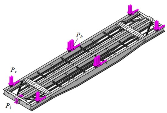
Figure 1.
Design diagram of the flatcar frame.
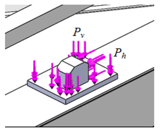
Figure 2.
Load diagram of a fixed fitting on the flatcar.
The flatcar was fixed on the horizontal surfaces of the center plates. The frictional forces between the center plates and center bowls were not taken into account.
The design values of the forces were taken equal to the values given in [20].
Tetrahedrons were taken as finite elements [23,24,25,26]. The graphic analytical method was used [27,28]. The method was based on a graphical (geometric) representation of admissible solutions and the objective function of the problem. The essence of the method in solving this problem is to build a dependence of the maximum equivalent stresses on the number of finite elements. When this dependence began to be described by a horizontal line, that indicated the optimum number of finite elements.
In this case, the number of elements forming the mesh was previously calculated. In the areas where there was a connection between the frame beams or parts, the mesh was automatically compacted. The number of nodes in the mesh was 311,601, and the number of elements was 932,166. The maximum element size was 100 mm, and the minimum was 20 mm. The finite element model of the bearing structure of the flatcar is shown in Figure 3.
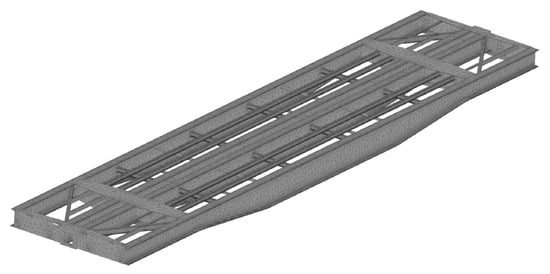
Figure 3.
Finite element model of the bearing structure of the flatcar.
The model was fastened in the areas of support on the bogies. Steel 09Mn2Si with the strength limit σL = 490 MPa and the fluidity limit σF = 345 MPa was taken as construction material.
The calculation was carried out using the von Mises criterion (the distortion criterion) or, as it is also called, the energy criterion (maximum-strain-energy theory). It was taken as the design criterion because the material of the flatcar frame (steel) is isotropic.
The results of the research are given in Figure 3. It was found that, during a shunting collision to the flatcar, the maximum equivalent stresses were about 418 MPa; they were concentrated in the fixed fittings (Figure 4). The maximum displacements amounted to 12.1 mm. This magnitude of displacements was due to the fact that the model was secured on the center plate and the middle part was loaded with the vertical force from the containers.
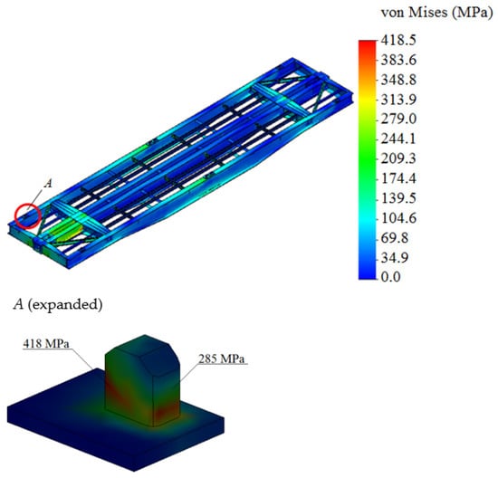
Figure 4.
Stress state of the flatcar frame.
Thus, the maximum equivalent stresses in the bearing structure of the flatcar with consideration of the displacements of the container fittings relative to the fixed fittings exceeded admissible values by 17%. The admissible stresses were taken equal to the yield strength of the structure material.
4. Experimental Determination of the Strength of the Flatcar
The strength of the bearing structure of the flatcar during a shunting collision was determined by means of full-scale tests in accordance with the “Programs and methods for testing the bearing structure of the flatcar”. This document was developed by the authors’ team and approved by the Research and Engineering Institute of Railway Transport under JSC Ukrzaliznytsia.
The test objects were a model 13-401M flatcar and two containers.
It is important to say that the developed “Program and methodology of testing” can be used for other versions of flatcars and containers.
The flatcar and containers were selected from those available at the station at which the tests were carried out. They were cleaned of dirt, and the remains of the cargo were transported and transferred for a technical inspection in order to prepare the relevant acts of selection and identification.
The representatives of the Department of Commercial Work and the authors of the article were attended. During examination, selection, and identification, the flatcar and containers were checked for defects, such as deformations, fractures, wear, bends, deflections, corrosion, breaks, loosening of fastening of nodes and parts, holes, and cracks.
The results of examination were used to establish that the flatcar and containers to be tested were fully repaired and in working condition.
The collision tests to determine the strength of the structural elements of the flatcar loaded with containers were carried out during daylight on a straight horizontal section of the railway track using a locomotive. Moreover, the following equipment was used:
- –
- Hammer wagon, the weight of which was more than the weight of the car under study;
- –
- Several freight cars (open wagons), the movement of which was restricted by rail shoes;
- –
- Dynamometric wagon with appropriate equipment (on the adjacent track).
At the same time, the difference between the axles of the automatic couplers of the car under study and those of the hammer wagon did not exceed 50 mm.
When wagons collided, the largest longitudinal force in the automatic coupler was in the range of the normative force value, i.e., 3.5 MN.
The procedure and technology used to prepare the car for the tests included the condition of the maximum technical compatibility and safety of all operations stipulated by the program.
The condition at which the test must be finished was to obtain the complete set of experimental data assigned by the test program or disruption of the integrity of the flatcar structure that might threaten the safety of tests.
Only those qualified and certified as required were permitted to the tests. The appropriate requirements regarding all stages of the tests were presented in the normative technical documentation on labor protection, fire and industrial safety, etc.
All operations on determining the strength and dynamic indicators of the bearing structure of the flatcar under a typical diagram of interaction between the fixed fittings and container fittings were performed by the authors’ team.
All operations on shunting were conducted by workers of the station or wagon depot.
All those involved in the tests were briefed on labor protection and safety and appropriately registered in the test log before the testing.
Only after that did the testing on the flatcar begin.
During the tests, the flatcar was loaded with coiled steel (Figure 5). The gross weight of the freight was identical to the gross weight of two containers.
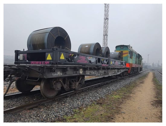
Figure 5.
Flatcar loaded with coiled steel.
The maximum stresses in the flatcar frame were determined with the method of strain gauging. The strain gauges were installed on the flatcar as presented in Figure 6. As far as it was technologically difficult to determine the stresses in the fixed fittings, the strain gauges were installed on the most loaded frame elements of the flatcar. They were found using the stress distribution fields in the flatcar frame by means of the FEM.
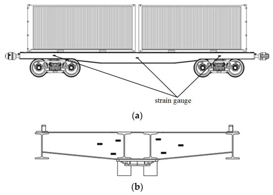
Figure 6.
Strain gauges on the frame: (a) on the side beam; (b) on the body bolster.
Their resistance was checked before testing. The resistance difference was no more than 3 Ohm. The strain gauges were also calibrated before testing.
The strain gauges were installed on the surfaces, which were prepared, cleaned, and treated with alcohol in advance. The prepared surfaces and the strain gauges were treated with a thin coat of glue, and when the glue dried, they were coated with glue again; after these procedures, the strain gauges were attached to the surface of the bearing structure. The strain gauges were glued with cyanoacrylate-based thermosetting adhesive. The gauges were pressed, and the remaining glue was removed. The outputs of the strain gauges were connected to the measuring equipment; some time was spent on glue drying. Before the installation of the strain gauges, the surfaces of the flatcar were dried with a heat gun. In order to exclude the influence of weather conditions while reading the gauges, they were coated with a thin Vaseline layer. Paraffin could also be used instead. A bitumen tape was used to secure the plates with compensating strain gauges (Figure 7).
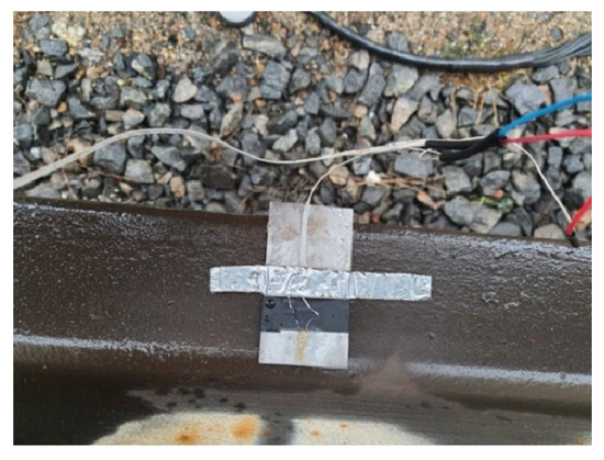
Figure 7.
Compensating strain gauge on the plate.
The insulation tapes were glued under the outputs of the strain gauges to prevent the contact between the outputs and the plates. A strain gauge amplifier was used to measure the stress (Figure 8).
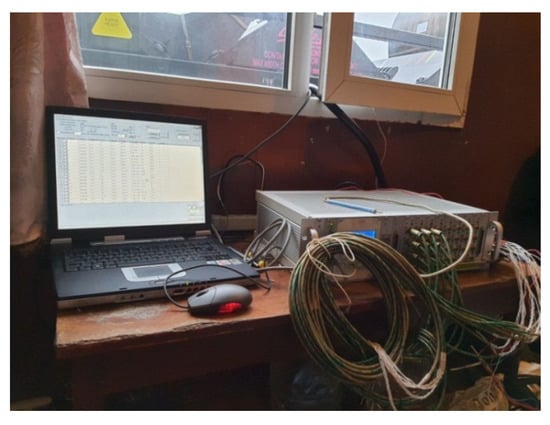
Figure 8.
Strain gauge amplifier.
The connection diagram of the sensors is shown in Figure 9.
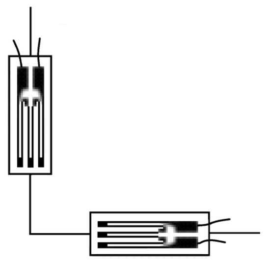
Figure 9.
Strain gauges connected.
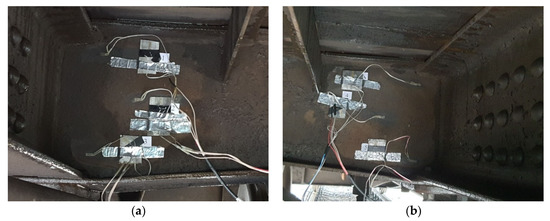
Figure 10.
Strain gauges on the body bolster: (a) left sheet; (b) right sheet.
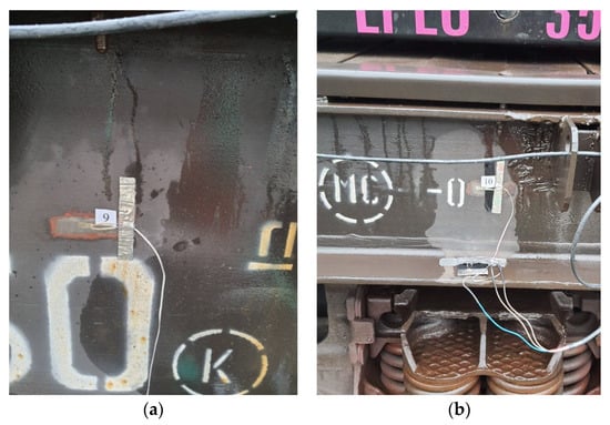
Figure 11.
Strain gauges on the main longitudinal beam of the flatcar: (a) middle part; (b) end part.
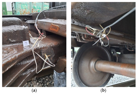
Figure 12.
Measuring devices on the flatcar: (a) strain gauges on the automatic coupler; (b) acceleration indicator.
Some strain gauges were installed on the automatic coupler to determine the impact force of it (Figure 12a). Besides, the accelerations of the flatcar frame and, therefore, the impact force, were determined with an acceleration indicator attached to the bearing structure of the flatcar (Figure 12b).
The strength tests for the flatcar were carried out at the dynamic mode with various impact speeds in the interval and conditions specified in [29]. The flatcar moved along a horizontal track section of the hump yard (Figure 13).

Figure 13.
Scheme of car collision.
Some chalk marks on the flatcar indicated the previous location of the fixed fittings (before colliding). The impact tests on the test car were carried out with some stationary retaining cars (retaining wall). These seven retaining open wagons were put on hold with a pneumatic brake (Figure 14).
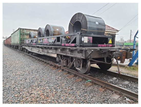
Figure 14.
Flatcar coupled to the retaining wall.
The car that was the first to be collided was additionally fixed with two brake shoes. The total weight of retaining cars exceeded 650 tons. The difference in the levels between the automatic couplers of the hammer car and the test car, and between the retaining cars and the test car, was 0.05 m. The hammer car rolled from the hump and collided the test flatcar. The rolling speed and the impact force were recorded. The weight of the hammer car was about 100 tons.
The pre-impact speed of the car was calculated by the following formula.
where t is the time during which the car passed the control section, s.
The time was measured with a stopwatch. After each collision, the flatcar was checked for damage. The displacements of the fixed fittings relative to their initial position were chalked before and after each collision.
The overall number of collisions the straight track section was 17. Among which seven collisions were made at a speed range of 3.0–6.0 km/h; seven collisions at a speed range of 6.0–10.0 km/h; and three collisions at the speeds over 10.0 km/h.
The maximum equivalent stresses were fixed by strain gauge 5. The test results are shown in Table 1.

Table 1.
The maximum stresses of the flatcar.
Figure 15 and Figure 16 show the dependence of the maximum stresses in the flatcar frame on time. The readings from strain gauges 2 and 5 can be considered as an example.
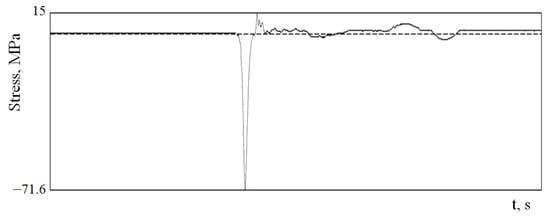
Figure 15.
Maximum equivalent stresses (Strain gauge 2).
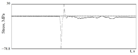
Figure 16.
Maximum equivalent stresses (Strain gauge 5).
It was found that the maximum stresses in the flatcar frame occurred during a collision.
The analysis of theoretical and experimental stresses in the flatcar frame is shown in Table 2.

Table 2.
The analysis of theoretical and experimental stresses in the flatcar frame (strain gauge 5).
The maximum difference between the test results was 17.0%.
It is necessary to mention that, after testing, no damage to the flatcar structure or containers was detected.
5. Verification of the Strength Model of the Flatcar
An F-criterion was used to verify the designed model of the bearing structure of the flatcar [30,31]:
where is the dispersion of adequacy and is the error mean square.
The values of dispersion of adequacy and reproducibility were determined in accordance with the classical formulas of probability theory and mathematical statistics.
In this case, this criterion was used to check the equality of dispersions of two samples. The number of sampling elements needed had been determined before the criterion was applied. For this, Student’s t-test, also known as Gusset’s criterion, was used.
In accordance with Fisher’s criterion, the model was adequate if its design value was less than the tabular one.
It was assumed that the model under study was linear (single factor) and described a change in the stresses of the flatcar frame according to the impact speed. The results of measurements are showed in Table 3 and Figure 17. The theoretical values of stress in the flatcar frame were determined according to the design diagram shown in Figure 1.

Table 3.
The stresses in the flatcar frame during a collision (strain gauge 5).
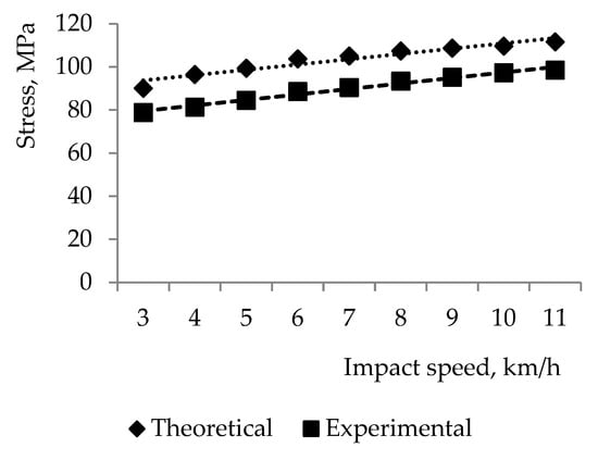
Figure 17.
Stresses in the flatcar frame.
The authors obtained the value Fp = 1.01, which was lower than Ft = 3.29. Thus, with a significance level of p = 0.05, the hypothesis on the adequacy of the designed model was not rejected.
It is important to say that the results of the study were used in the doctoral dissertation recently defended by one of the authors of this article, and for recommendations on designing modern containers, which later were submitted to two Ukrainian railcar-building enterprises for further implementation
The results of the study can be used not only for designing and modernizing flatcars, but also open wagons, which have already come into service for transportation of containers. This solution has been implemented due to the lack of vehicles intended for container transportation. Today, the amount of freight transported in containers along international corridors is increasing. When transported in the open wagon, the container can be fastened by means of fixed fittings welded to the floor, i.e., these elements are immovable. The open wagon frame and containers in it are under the impact of the same loads at operating modes. The solid-bottom open wagon is mostly used for transportation of containers. The issues of container transportation are of theoretical and practical interest, as well as very urgent. Therefore, they will certainly be highlighted in further publications of the authors’ team.
6. Conclusions
- The study includes the determination of the strength characteristics of the bearing structure of a flatcar. The calculation was made using the finite element method. The maximum equivalent stresses in the bearing structure of the flatcar were about 418 MPa, and they were concentrated in the fixed fittings. The maximum equivalent stresses in the bearing structure of the flatcar, including the displacements of the container fittings relative to the fixed fittings, exceeded admissible values by 17%. The maximum displacements were recorded in the middle parts of the main longitudinal beams of the flatcar; they were 12.1 mm.
- The study also included the experimental determination of the strength characteristics of the bearing structure of the flatcar using the method of electrical strain gauging. The places of the strain gauges in the flatcar frame were found on the basis of the theoretically obtained stress fields. The authors formulated “The programs and methods for testing the bearing structure of the flatcar”. The tests were carried out for three impact speed ranges: 3–6 km/h, 6–10 km/h, and over 10 km/h. The number of collisions was selected according to the normative technical documentation. The maximum difference between the results of theoretical and experimental tests was 17.0%.
- The strength model designed for the flatcar frame was verified. The calculation was carried with an F-test, and it was found that the design value of the criterion was Fp = 1.01; thus, it was lower than the tabular value Ft = 3.29. Therefore, the hypothesis on adequacy was not rejected.
Based on the study, it was concluded that the improved diagram of interaction could be used to reduce damage to the bearing structure of the flatcar.
Author Contributions
Conceptualization, G.V., J.G. and A.L.; methodology, G.V., J.G. and A.L.; software, A.L.; validation, O.F., A.L. and A.O.; investigation, A.L. and O.K.; resources, J.G., A.L. and O.K.; writing—original draft preparation, A.L., O.F., A.O. and O.K.; writing—review and editing M.P. and D.P.; visualization, G.V., A.L. and D.P.; supervision, A.O. and M.P. All authors have read and agreed to the published version of the manuscript.
Funding
This publication was realized with support of Operational Program Integrated Infrastructure 2014–2020 of the project: Innovative Solutions for Propulsion, Power and Safety Components of Transport Vehicles, code ITMS 313011V334, co-financed by the European Regional Development Fund and VEGA 1/0513/22. Investigation of the properties of railway brake components in simulated operating conditions on a flywheel brake stand.
Institutional Review Board Statement
Not applicable.
Informed Consent Statement
Not applicable.
Data Availability Statement
Not applicable.
Conflicts of Interest
The authors declare no conflict of interest.
References
- Steišunas, S.; Dižo, J.; Bureika, G.; Žuraulis, V. Examination of Vertical Dynamics of Passenger Car with Wheel Flat Considering Suspension Parameters. In Proceedings of the 10th International Scientific Conference TRANSBALTICA 2017, Vilnius, Lithiania, 4–5 May 2017; Elsevier: Amsterdam, The Netherlands, 2017. [Google Scholar] [CrossRef]
- Dižo, J.; Blatnický, M.; Steišunas, S. Assessment of a rail vehicle running with the damaged wheel on a ride comfort for passengers. In Proceedings of the 22nd Slovak-Polish Scientific Conference on Machine Modelling and Simulations, MMS2017, Sklene Teplice, Slovak, 5–8 September 2017. [Google Scholar] [CrossRef]
- Soukup, J.; Skocilas, J.; Skocilasova, B.; Dizo, J. Vertical vibration of two axle railway vehicle. In Proceeding of the 21nd Slovak-Polish Scientific Conference on Machine Modeling and Simulations, MMS2016, Hucisko, Poland, 6–8 September 2016. [Google Scholar] [CrossRef]
- Makeev, S.V.; Builenkov, P.M. Features of the Calculation of the Stress-Strain State of the Tank-Container, Taking into Account the Actual Loading in Operation. SCIENCE—EDUCATION—PRODUCTION: Experience and Development Prospects: Collection of Materials of the XIV International Scientific and Technical Conference Dedicated to the Memory of Doctor of Technical Sciences, Professor E.G. Zudov (8–9 February 2018): In 2 Volumes—T 1: Mining and Metallurgical Production. Mechanical Engineering and Metalworking.—Nizhny Tagil: NTI (Branch); Ural Federal University: Ekaterinburg, Russia, 2018; pp. 174–184. (In Russian) [Google Scholar]
- Zamecnik, J.; Jagelcak, J. Evaluation of wagon impact tests by various measuring equipment and influence of impacts on cargo stability. Communications 2015, 4, 21–27. [Google Scholar]
- Mrzyglod, M.; Kuczek, T. Uniform crashworthiness optimization of car body for high-speed trains. Struct. Multidiscip. Optim. 2014, 49, 327–336. [Google Scholar] [CrossRef]
- Ermolenko, I.Y.; Zheleznyak, V.N. Research of rolling stock dynamics using an experimental laboratory car when moving along difficult sections of the ESSR road. Mod. Technol. Syst. Anal. Model. 2016, 4, 199–203. (In Russian) [Google Scholar]
- Chepurnoy, A.D.; Litvinenko, A.V.; Sheichenko, R.I.; Graborov, R.V.; Chuban, M.A. Running strength and dynamic tests of the platform car. Bull. NTU “KhPI” 2015, 31, 111–128. (In Russian) [Google Scholar]
- Zhong, Y.-G.; Zhan, Y.; Zhao, G. Fatigue Analysis of Structure of Gondola Car Body Based on Rigid-flexible Coupling Multi-body Systems. In Proceedings of the 11th World Congress on Computational Mechanics (WCCM XI), Barcelona, Spain, 20–25 July 2014. [Google Scholar]
- Yuan, Y.Q.; Li, Q.; Ran, K. Analysis of C80B Wagons Load-Stress Transfer Relation. Appl. Mech. Mater. 2012, 148–149, 331–335. [Google Scholar] [CrossRef]
- Yoon, S.C. Evaluation of Structural Strength in Body Structure of Freight Car. Key Eng. Mater. 2010, 417–418, 181–184. [Google Scholar] [CrossRef]
- Vatulia, G.; Fomin, O.; Lovska, A.; Okorokov, A.; Pavliuchenkov, M.; Petrenko, D. Experimental Research into the Strength of a Flat Car with Elastic Interaction between Fixed Fittings of a Flat Car and Container Fittings. AIP Conf. Proc. 2022, 2557, 070002. [Google Scholar] [CrossRef]
- Lovskaya, A.; Ryibin, A. The study of dynamic load on a wagon-platform at a shunting collision. East.-Eur. J. Enterp. Technol. 2016, 3, 4–8. [Google Scholar] [CrossRef]
- Nikitchenko, A.; Artiukh, V.; Shevchenko, D.; Prakash, R.V. Evaluation of Interaction between Flat Wagons and Container at Dynamic Coupling of Flat Wagonss. MATEC Web Conf. 2016, 73, 04008. [Google Scholar] [CrossRef]
- Bogomaz, G.I.; Mekhov, D.D.; Pilipchenko, O.P.; Chernomashentseva, Y.G. Loading of Tank-Containers Located on a Railway Platform When Hitting an Automatic Coupler; Collection of Scientific Papers “Dynamics and Rotation of Mechanical Systems”; Institute of Technical Mechanics under NAS: Kiev, Ukraine, 1992; pp. 87–95. (In Russian)
- Chłus, K.; Krasoń, W. Dynamic analysis of railway platform chassis model. J. KONES Powertrain Transp. 2011, 18, 93–100. [Google Scholar]
- Chłus, K.; Krasoń, W. Numerical standard tests of railway carriage platform. J. KONES Powertrain Transp. 2012, 19, 59–64. [Google Scholar] [CrossRef]
- Marinoshenko, S. Switching over to the home platform. J. Partn. Transmashhold. 2015, 3, 22–23. [Google Scholar]
- Fomin, O.; Gerlici, J.; Gorbunov, M.; Vatulia, G.; Lovska, A.; Kravchenko, K. Research into the Strength of an Open Wagon with Double Sidewalls Filled with Aluminium Foam. Materials 2021, 14, 3420. [Google Scholar] [CrossRef] [PubMed]
- Kondratiev, A.V.; Gaidachuk, V.E. Mathematical analysis of technological parameters for producing superfine prepregs by flattening carbon fibers. Mech. Compos. Mater. 2021, 1, 91–100. [Google Scholar] [CrossRef]
- Panchenko, S.; Gerlici, J.; Vatulia, G.; Lovska, A.; Pavliuchenkov, M.; Kravchenko, K. The analysis of the loading and the strength of the flat rack removable module with viscoelastic bonds in the fittings. Appl. Sci. 2023, 13, 79. [Google Scholar] [CrossRef]
- Panchenko, S.; Vatulia, G.; Lovska, A.; Ravlyuk, V.; Elyazov, I.; Huseynov, I. Influence of structural solutions of an improved brake cylinder of a freight car of railway transport on its load in operation. Eureka Phys. Eng. 2022, 6, 45–55. [Google Scholar] [CrossRef]
- Alyona, L.; Oleksij, F.; Václav, P.; Pavel, K. Dynamic load and strength determination of carrying structure of wagons transported by ferries. J. Mar. Sci. Eng. 2020, 8, 902. [Google Scholar] [CrossRef]
- Alyona, L. Assessment of dynamic efforts to bodies of wagons at transportation with railway ferries. East.-Eur. J. Enterp. Technol. 2014, 3, 36–41. [Google Scholar] [CrossRef]
- Šastniak, P.; Moravčík, M.; Baran, P.; Smetanka, L. Computer aided structural analysis of newly developed railway bogie frame. MATEC Web Conf. 2018, 157, 02051. [Google Scholar] [CrossRef]
- Štastniak, P. Freight long wagon dynamic analysis in S-curve by means of computer simulation. Manuf. Technol. 2015, 15, 930–935. [Google Scholar] [CrossRef]
- Kondratiev, A.; Píštěk, V.; Smovziuk, L.; Shevtsova, M.; Fomina, A.; Kučera, P.; Prokop, A. Effects of the temperature–time regime of curing of composite patch on repair process efficiency. Polymers 2021, 13, 4342. [Google Scholar] [CrossRef] [PubMed]
- Fomin, O.; Lovska, A.; Gorbunov, M.; Gerlici, J.; Kravchenko, K. Dynamics and strength of circular tube open wagons with aluminum foam filled center sills. Materials 2021, 14, 1915. [Google Scholar] [CrossRef] [PubMed]
- DSTU 7598:2014; Freight Wagons. General Requirements for Calculations and Design of New and Modernized Wagons of 1520 mm Track (Non-Self-Propelled). UkrNDNTS: Kiev, Ukraine, 2015; 162p. (In Ukrainian)
- Ivchenko, G.I.; Medvedev, Y.I. Mathematical Statistics; LIBROCOM: Moscow, Russia, 2014; 352p. (In Russian) [Google Scholar]
- Rudenko, V.M. Mathematical Statistics; Center of Educational Literature: Kiev, Ukraine, 2012; 304p. (In Russian) [Google Scholar]
Disclaimer/Publisher’s Note: The statements, opinions and data contained in all publications are solely those of the individual author(s) and contributor(s) and not of MDPI and/or the editor(s). MDPI and/or the editor(s) disclaim responsibility for any injury to people or property resulting from any ideas, methods, instructions or products referred to in the content. |
© 2023 by the authors. Licensee MDPI, Basel, Switzerland. This article is an open access article distributed under the terms and conditions of the Creative Commons Attribution (CC BY) license (https://creativecommons.org/licenses/by/4.0/).