Article

A Novel Moving Object Detection Algorithm Based on Robust Image Feature Threshold Segmentation with Improved Optical Flow Estimation

1
Coal Industry Engineering Research Center of Mining Area Environmental and Disaster Cooperative Monitoring, Anhui University of Science and Technology, Huainan 232001, China
2
School of Geomatics, Anhui University of Science and Technology, Huainan 232001, China
3
School of Environment and Spatial Informatics, China University of Mining and Technology, Xuzhou 221116, China
*
Author to whom correspondence should be addressed.
Appl. Sci. 2023, 13(8), 4854; https://doi.org/10.3390/app13084854
Submission received: 19 February 2023 / Revised: 6 April 2023 / Accepted: 9 April 2023 / Published: 12 April 2023
(This article belongs to the Section Computing and Artificial Intelligence)

Abstract

:
The detection of moving objects in images is a crucial research objective; however, several challenges, such as low accuracy, background fixing or moving, ‘ghost’ issues, and warping, exist in its execution. The majority of approaches operate with a fixed camera. This study proposes a robust feature threshold moving object identification and segmentation method with enhanced optical flow estimation to overcome these challenges. Unlike most optical flow Otsu segmentation for fixed cameras, a background feature threshold segmentation technique based on a combination of the Horn–Schunck (HS) and Lucas–Kanade (LK) optical flow methods is presented in this paper. This approach aims to obtain the segmentation of moving objects. First, the HS and LK optical flows with the image pyramid are integrated to establish the high-precision and anti-interference optical flow estimation equation. Next, the Delaunay triangulation is used to solve the motion occlusion problem. Finally, the proposed robust feature threshold segmentation method is applied to the optical flow field to attract the moving object, which is the. extracted from the Harris feature and the image background affine transformation model. The technique uses morphological image processing to create the final moving target foreground area. Experimental results verified that this method successfully detected and segmented objects with high accuracy when the camera was either fixed or moving.

1. Introduction

Image applications are ubiquitous, and the availability of various sensors and platforms such as satellites, mobile phones, and drones is constantly increasing. Indoor positioning, video surveillance, and other social applications have an increasing demand for image reliability and current information. Sensor systems for real-time indoor and outdoor mapping, such as stereo-RGB cameras, RGB-D depth cameras, and other sensors’ consumer markets, are constantly growing and low-cost sensors are ubiquitous, especially as the technology in smartphones and the Internet of Things grows increasingly advanced, which is a strong impetus for the development of real-time monitoring and mapping capabilities in indoor and outdoor environments. Moving object detection is an important aspect of real-time detection and mapping and includes detecting and extracting rigid or non-rigid moving objects in the complex background environments of an image sequence or video format. It has been one of the most prominent research areas of image vision and is frequently used in various fields such as video surveillance, assisted driving, scene analysis, target tracking, and target localization [1,2,3,4,5]. Moving objects are primarily detected using three methods: consecutive frame difference [6], background subtraction [7], and optical flow [8]. The consecutive frame difference method extracts moving objects by differencing two or more successive frames; however, it can only detect targets in a fixed backdrop because determining the target detection threshold is quite tricky. The problem of voids often accompanies the results; moreover, this method is easily disturbed by illumination variation and image noise [9,10,11]. The background subtraction method recovers the moving object by differentiating the background model from the current frame. Nevertheless, the algorithm’s accuracy is affected by the background modeling method, making it highly complicated. Moreover, this approach is deeply disturbed by the ‘ghosting’ problem [12,13,14]. The optical flow method detects moving objects by calculating the flow vector between each pixel in the current frame and the pixel of the same name in the next frame. Next, it thresholds the image’s optical flow field to identify moving objects [15,16,17]. Compared with the other two methods, the optical flow method requires no previous knowledge. It can directly estimate the moving object area and generate the motion parameters of moving objects. The optical flow method exhibits higher accuracy and robustness and has a better detection performance for targets with scale changes or deformations.
The optical flow method of moving object detection and extraction essentially entails thresholding, classifying, and morphologically processing the optical flow vector values of each image’s pixel in turn and then extracting the foreground region of the moving object. Adrian G. Bors et al. [18] were the first to apply the image optical flow estimation to the detection segmentation of moving objects. They used the median radial basis function neural network to divide the images into different regions, such as the still image and motion information, and fuse other motion regions of the same target to extract moving objects. Sasa Galic et al. [19] suggested object detection by optical flow and clustering for medical images. Moreover, they proposed the Euclidean norm of the optical flow vector and used it as the clustering features. However, their algorithm had low accuracy and a poor extraction effect with a moving background. Shui-gen Wei et al. [20] introduced the Otsu algorithm to the optical flow method of target detection. They first normalized the optical image flow as a grey image. Next, they used the Otsu algorithm to translate it into a binary image. The Otsu algorithm is the primary method of the optical flow method for motion target detection [21,22,23,24]. Their target extraction results were better under stationary background conditions but poorer results were obtained with a moving background. Furthermore, Sengar et al. [16] calculated the total optical flow by computing the optical flow between three consecutive frames and combining the HS optical flow vector fields between the current frame and the previous frame and between the current frame and the next frame. Then, they used Otsu thresholding to detect moving objects with high detection accuracy; however, the secondary optical flow estimation significantly increased the time consumption. Han et al. [25] used the homography matrix to construct the optical flow background model and RANSAC to solve and optimize the model. Next, they determined the adaptive threshold of optical flow according to the estimated background model. The optical flow threshold size can be adaptively adjusted with the change in the camera motion. However, the algorithm accuracy is affected by the background model, and the moving object extraction is disturbed by the ‘ghosting’ problem. Wei Sun et al. [26] determined the average amplitude value of optical flow as the threshold and put results into the HSV color space to mark and remove the shadow. However, the detected moving object still has hole problems so the method is only used on a rigid moving object.
Above all, the three issues in detecting moving objects by the optical flow algorithm should be resolved; meaning, first, the influence of illumination variation and the false detection of moving objects when there are illumination changes in the image sequence. Second, the ‘ghosting’ problem, due to the change in the position of the moving object which causes the background area to be covered by the region of the moving target in the previous frame while the background area appears in the next frame without being obscured and is mistakenly detected as the moving object area. Third, camera jittering or the movement that occurs when the camera may be non-fixed or dithered in acquiring image frames, which can change the image sequence background. Still, the commonly used optical flow moving object detection method is only used for a fixed background.
A moving object detection algorithm based on optical flow estimation and robust feature points was examined in this paper to address the problems of illumination variation, ‘ghosting’, dynamic texture interference, and camera jittering or movement. First, the algorithm predicts the image’s optical flow field. Then, according to the optical flow residual principle, the local optical flow calculation of the Lucas–Kanade (LK) optical flow method is integrated into the Horn–Schunck (HS) optical flow method to constitute the optical flow equation data item to estimate the optical flow vector. Next, the Delaunay triangulation is applied to solve the motion occlusion problem, establishing the high-precision optical flow estimation energy equation.
Furthermore, it is necessary to further threshold the optical flow vector field to determine the moving object’s foreground area. The Otsu algorithm is often applied in the threshold processing of the optical flow method of moving object detection because it has better detection results in a fixed background environment. However, the object segmentation results are poor when the camera is jittering or moving. To solve this problem, this study proposes an optical flow threshold algorithm based on robust feature points. The threshold is determined according to the Harris robust feature points of the background area instead of the traditional optical flow Otsu threshold method to extract the foreground area of moving targets. The proposed algorithm can then be applied in either condition: when the camera is moving or when it is fixed. Importantly, this algorithm offers more accurate detection and extraction results for rigid and non-rigid targets.
The main contributions are made as follows:
  • We adopted a dense optical flow estimation algorithm that combines the HS pyramid large displacement optical flow method with the LK local optical flow method to improve the robustness of the algorithm and introduced the DF-β based on an edge-preserving strategy as the smoothing term of the optical flow energy equation to ensure edge integrity.
  • We adopted the non-quadratic penalty function and Delaunay triangulation occlusion determination to reduce the inaccuracy of optical flow estimation caused by the ‘ghost’ problem and to improve the accuracy of moving object detection.
  • We proposed a moving object detection algorithm based on optical flow thresholding of Harris robust feature points. According to the MSAC algorithm, the background model is calculated, and the background robust feature points are screened. The optical flow value of the Harris robust feature points is used as the threshold and can be applied to both a static or moving camera.

2. Materials and Methods

2.1. Algorithm Framework

Figure 1 illustrates the framework of the algorithm for detecting moving objects with advanced estimated optical flow robust feature threshold segmentation which is primarily comprised of two parts. First, the LK optical flow local calculation is combined with the HS dense optical flow estimation to formulate the energy equation. The image pyramid is then constructed for estimating a large displacement optical flow. Similarly, the Delaunay triangulation is used to determine the motion occlusion and iteratively compute the image optical flow field from up to down. Second, the Harris feature points are extracted. The affine transformation matrix of the background model between the current and next frames is then collected. Moreover, robust feature points are selected, and the optical flow value at the robust feature points is applied as the optical flow threshold to extract the moving object. Then, the binary image of the extracted moving object is processed by image morphology via expansion, corrosion, open operation, and closed operation.

2.2. Improved Optical Flow Estimation Method

2.2.1. Improved Optical Flow Estimation Energy Equation

The optical flow field estimation results directly affect the accuracy of moving object detection and extraction. To enhance the algorithm’s anti-interference of illumination variation and the robustness in the case of the rotation and warping of moving objects or background regions, the energy equation of optical flow estimation in this paper is designed to include two parts: data term  E D a t a  and smoothing term  E S m o o t h . The energy equation is expressed as follows:  E = E D a t a + α E S m o o t h .
The data term is designed to fuse image brightness conservation and first derivative gradient conservation:
E D a t a = Ω Ψ [ γ 1 I x + u , y + v , t + 1 I x , y , t 2 + γ 2 ( I x + u , y + v , t + 1 I x , y , t ) 2 ] d x d y
where  γ 1  and  γ 2  are the coefficients of the grey and gradient term [27], respectively,  Ψ X = X 2 + ξ 2 , a n d   ξ  is the non-square penalty function [28]. ξ is just for the numerical reason and can be set to a fixed value to ensure the Ψ can always be a convex function in the minimization process. Due to the small positive constant ξ, we set  ξ = 0.001 .
The spatial gradient was defined as  3 I = [ I x I y I t ] T . The partial derivatives of the spatial gradient in the x and y directions are  3 I x = [ I x x I x y I x t ] T  and  3 I y = [ I x y I y y I y t ] T ω = [ u v 1 ] T  represents the optical flow vector based on the assumption of brightness constancy:  [ ( 3 I x ) T + ( 3 I y ) T ] ω = 0 . The data term can be expressed as follows:
E D a t a = Ω Ψ { ω T [ γ 1 3 I ( 3 I ) T + γ 2 ( 3 I x ( 3 I x ) T + 3 I y ( 3 I y ) T ) ] ω } d x d y
The HS global optical flow method can determine the dense image optical flow field. However, because the data term of its energy equation is constructed based on the changes in brightness and gradient, the HS method has low robustness to image noise and dynamic texture such as shaking leaves, water, and fog. In contrast, the LK local optical flow estimation method exhibits higher anti-interference of those elements. Therefore, the local convolution kernel function  K ρ  of the LK method data term was introduced [29].  K ρ  represents the Gaussian kernel function with a variance of  ρ  for improving the robustness of noise and dynamic texture. Therefore, the data term fuses the HS and LK optical flow energy equations as follows:
E D a t a = Ω Ψ { ω T K ρ [ γ 1 3 I 3 I T + γ 2 ( 3 I x 3 I x T + 3 I y ( 3 I y ) T ) ] ω } d x d y
The smoothing term is designed as the edge-preserving strategy  D F β (decreasing scalar function) [30]. The smoothing term is defined as follows:
E S m o o t h = Ω Ψ [ ( e λ I t + β ) ( u 2 + v 2 ) ] d x d y
s . t .   u = ( u x u y ) T , v = ( v x v y ) T

2.2.2. Occlusion Determination Based on the Delaunay Triangulation

The motion occlusion problem, also known as ‘ghosting’, has always been difficult to solve in optical flow estimation and moving object detection. The movement of the objects between the previous and subsequent images causes the formation of a ‘ghost’ when the background area covered by the moving foreground in the last frame is exposed in the following frame. Figure 2 shows that from  I t  to  I t + 1 , the occluded point  P 1  in the  I t  image appears in  I t + 1  because of the movement of foreground objects, whereas points  P 2  and  P 3  change from appearance to occlusion. From  I t + 1  to  I t + 2 , the occluded point  P 2  changes from occlusion to appearance. All these points bring a false optical flow and lead to ‘ghosting’ problems. Two methods were used to solve this problem: the first is the general introduction of the punishment mechanism using the non-square penalty function. The second is to combine the Delaunay triangulation to ascertain occlusion decisions in the moving edge regions.
Only relying on the non-square penalty function cannot solve the occlusion problem well; the Delaunay [31] triangulation occlusion judgment was also incorporated to increase the accuracy of moving object extraction. The Delaunay structure and optical flow estimation proposed by Congxuan Zhang et al. [32] were applied to determine whether the point is a moving occlusion point. Because motion occlusion occurs in the edge region of the moving target, the occlusion is determined by detecting the brightness variations of the pixels’ triangular grid in the edge regions of the moving object. The optical flow estimation after occlusion processing is defined as  ω Λ , and its calculating equation is defined as follows:
ω Λ = Λ ω
s . t .   Λ = 1 normal 0 occlusion
where  ω = ( u v ) T  is the optical flow vector field and  Λ  represents the occlusion of each pixel. The Λ judgment method is divided into two steps:
The motion edge region information  R e d g e  in the image can be extracted according to the estimated image optical flow field. The calculation equation is expressed as follows:
R e d g e = e d g e ( ω , L a p l a c i a n )
where the ‘edge’ represents the boundary extraction algorithm and the Laplacian edge detection algorithm is used.
According to the estimated image optical flow vector field, each pixel point position  B = ( i j ) T  in  I t  was calculated and added to  ω = ( u v ) T  at the same points to determine the corresponding point  I t + 1 ( i + u y + v )  in  I t + 1 . Next, the grey difference  Δ I  of  I t + 1  and  I t  of the estimated optical flow corresponding points were calculated. The calculation equation is defined as follows:
Δ I = I t + 1 B + ω I t ( B )
when  Δ I = 0 , the corresponding position of the continuous frames has a consistent grey level, indicating that point B is not occluded,  Λ = 1 .
When ΔI ≠ 0, the occlusion situation needs to be determined on a case-by-case basis. For the under-determined point in the  R e d g e  of  I t , the change in the brightness value of the triangle to which it belongs is calculated. Similarly, the Delaunay triangulation about the brightness difference map is constructed to determine the occlusion. Specifically,  B 1 i , j  is taken in  I t  along with the adjacent coordinate points  B 2 i + 1 , j  and  B 3 ( i , j + 1 ) , which constitutes the determination of the Delaunay triangulation. The Delaunay triangulation area can be calculated as follows:
Δ I Δ = φ 1 Δ I B 1 + φ 2 Δ I B 2 + φ 3 Δ I B 3
where  φ 1 φ 2 ,  and  φ 3  represent the weights of three points  B 1 B 2 ,  and  B 3 , respectively, because they are adjacent coordinate points:  φ 1 = φ 2 = φ 3 = 1 / 3 . The greyscale difference was compared between the triangulation and the pixel points in a 25 × 25 neighborhood size around it to determine the occlusion of the point in the domain. The specific determination method is: if  Δ I B > Δ I Δ , the point is occluded and  Λ = 0 . If  Δ I B < Δ I Δ , the point is not occluded and  Λ = 1 .
The pseudo-code of improved optical flow estimation is as Algorithm 1:
Algorithm 1 Improved optical flow estimation
Input I t  and  I t + 1  in image sequence
Output: Optical flow estimation result  ω Λ  of  I t  at time t
  Build the image pyramid  I t k  and  I t + 1 k  from bottom to up, which  k ( 1,2 , n )
QCalculate the initial value of the top-level optical flow  ω t 1
  for k = 2 to n do
   The optical flow of current layer  d ω t k  is calculated according to  E = E D a t a + α E S m o o t h
Calculate the initial optical flow of next layer  ω t k + 1 = ω t k + d ω t k
  end
  The optical flow of the current image  I t  is updated as  ω = ω t n
  Detecting the edge of optical flow  ω t n  as  R e d g e = e d g e ( ω , s o b e l )
  Delaunay triangulation is established in the edge area  R e d g e
  Calculating the grey difference:  Δ I = I t + 1 B + ω I t ( B )
  if  Δ I = 0
    Λ = 1
  else
   for i = 1 to K
     Calculating the change in brightness of triangle  B 1 i  point:
      Δ I Δ = φ 1 Δ I B 1 + φ 2 Δ I B 2 + φ 3 Δ I B 3
     if  Δ I B > Δ I Δ
       Λ = 0
     else
       Λ = 1
     end
end
Estimating the optical flow after occlusion judgment:  ω Λ = Λ ω
Figure 3 shows the effects of occlusion determination on image optical flow estimation. The optical flow in the right side of the head and the bottom of the arm of the moving target is termed a ‘ghost’ due to motion occlusion. The optical flow in the ‘ghost region’ should be the same as the background region, which produces a false optical flow in the occlusion area. It has a wrong optical flow estimation. The optical flow estimation after occlusion removal can be corrected more after motion occlusion processing, thereby improving the accuracies of optical flow estimation and the subsequent motion target region extraction. The optical flow estimation map following occlusion removal can be viewed to be more corrected after motion occlusion processing, which increases the accuracies of optical flow estimation and subsequent motion target area extractions.

2.3. Moving Object Detection Based on Robust Feature Threshold Segmentation

Estimating the optical flow between successive frames can determine the optical flow vector field and compute the motion vector of each point. However, the position and state of the moving target in the image cannot be detected. The optical flow vector must be further processed to determine the specific moving target area. Hence, a moving object detection method based on the threshold segmentation of Harris robust background feature points was suggested to detect and segment moving object foreground regions in the stationary and moving backgrounds.
First, the Harris feature points in the current frame are extracted. Their positions in the next frame are calculated according to their corresponding optical flow values. Then, based on the principle that the image background conforms to the graphical affine transformation, the Harris feature points and their corresponding positions are combined in the next image. According to the M-estimators Sample Consensus (MSAC) algorithm [33], the feature points that do not belong to the background model and their optical flow values are excluded from solving the affine transformation homography matrix on the image background model. Robust Harris feature points are known as the Harris feature points of the background region. The robust feature points’ optical flow value is used as the threshold to segment the foreground region of the moving object; hence, the binary image of the foreground of the moving target is obtained. Finally, morphological image processing is used to deal with the issues of pores, discontinuities, and irregular moving edges in the binary image and create the foreground mask of the moving target regions.
The algorithm mainly includes three steps: (1) image optical flow vector field normalization processing; (2) optical flow thresholding processing based on Harris robust feature points; and (3) image morphological processing of the target foreground region.
(1) Image optical flow vector field normalization processing
Because the estimated optical flow vector field cannot be directly thresholded, it is necessary to normalize the optical flow vector field to transform the optical flow vector field of the image into a grey value image based on the optical flow.
First, the Euclidean norm of the optical flow vector value  ω ( x , y ) = [ u v ]  at each pixel point is calculated and used as the optical flow grey value V ( x , y )  at this point. The calculation formula is expressed as follows:
V x , y = u ( x , y ) 2 + v ( x , y ) 2
Next, the obtained image optical flow grey value V ( x , y )  is normalized to determine the normalized grey image  V n o r m :
V n o r m x , y = V x , y V m i n V m a x V m i n
s . t .   V m a x = max ( u x , y 2 + v x , y 2 ) ;   V m i n = min ( u x , y 2 + v x , y 2 )
(2) Optical flow thresholding processing based on Harris robust feature points
This study found that the feature points in the common scene are fixed no matter whether the camera is moving or stationary. Furthermore, due to the background movement caused by the camera movement, the position change of the feature points in the background area of the front and back frames conforms to the image affine transformation, whereas the relative position of the feature points in the moving object area changes in the front and back frames, which does not conform to the affine transformation. Therefore, an affine transformation matrix was built to solve the background model between the adjacent frames.
Because the optical flow estimate of the image pixel depicts a certain error, the optical flow estimate of the pixel point has a higher estimation accuracy at the image brightness change area and the image gradient change area. Moreover, the affine transformation matrix [25] calculation does not require the global pixel points and their optical flow values. Therefore, the feature points and their optical flow value were extracted. Next, the homography matrix  M  of the affine transformation of the background region model was calculated according to the feature points and their optical flows. Because the background region of the previous frame image can be transformed into the background region of the next frame image by the affine transformation, the homography matrix  M  of the affine transformation of the background model at the time of  t t + 1  should satisfy the following equation:
M t t + 1 I t B = I t + 1 B
where  I t B = i j 1 T  represents each pixel in the image background area at time t I t + 1 B  represents each pixel in the image background area at time  t + 1 ; and  M t t + 1  represents the background model affine transformation matrix calculated from time  t  to  t + 1 .
According to the optical flow estimation, the corresponding points in the next frame image  I t + 1 B  can be determined by adding each pixel  ( i j 1 ) T  in  I t B  into its estimated optical flow value  ω = ( u v 0 ) T  and is expressed as follows:
I t + 1 B = I t B + ω
Because the affine transformation of the background region and the optical flow estimation of the same image are equal to the corresponding points in the next frame image  I t + 1 B  (combining Equations (11) and (12)), the affine transformation matrix calculation with a background model of size  3 × 3  can be determined as follows:
M t t + 1 I t B = I t B + ω
The MSAC algorithm was used to solve and optimize Equation (13) to exclude the feature points that do not belong to the background model because of the uncertainty of the location of the extracted feature points which may be located in the background area or the foreground area. To increase the computational efficiency, feature points and the corresponding optical flow estimation were calculated to calculate the affine transformation matrix on the optical flow of feature points. This process finally filters out the stable feature points in the background model area, known as robust feature points.
Figure 4 shows the outcomes of robust feature point extraction, wherein Figure 4a,b depict the current and the next frames, respectively. Figure 4c shows the feature points extracted by the features from the accelerated segment test (FAST) feature extraction algorithm [34] in the previous image. Figure 4d presents the FAST robust background feature points, which are selected from the FAST feature points by background model affine transformation matrix calculation and MSAC methods with their optical flow values. Figure 4e,f illustrate the speeded-up robust features (SURF) feature points [35] and the SURF robust background feature points, respectively. Figure 4g,h show the Harris feature [36] points and the Harris robust background feature points, respectively. The results demonstrate less feature information extracted by the FAST algorithm in Figure 4c. The final selected background robust feature points are concentrated in one area, which easily causes estimation errors in the calculated background model affine transformation matrix. It is difficult to screen out the correct background feature points. The SURF feature points in the moving target area are misinterpreted as the background feature points in Figure 4d. Figure 4e shows that the number of feature points extracted by SURF is too much, which increases the computational complexity of the background model matrix. The final extracted robust feature points also constitute the feature points in the moving target area (Figure 4f). Figure 4g,h demonstrate that the Harris feature extracts the feature points at the strong inflection points, which are more robust. The Harris feature points are quantity reasonable and distribution balanced. The screened robust feature points were shown in Figure 4h with no mistakes. The results revealed that the Harris robust background feature points are more accurate than FAST and SURF and are more suitable for estimating the background change model. All the robust background feature points screened exhibit the highest accuracy.
After determining the robust feature points, the moving object foreground area is segmented according to the optical flow value of the robust feature points, and the moving object area is retrieved. The maximum optical flow value of the robust feature points was used as the optical flow threshold for moving object extraction. The maximum grey value constant in the background feature points is used as a threshold, and the binary image of the foreground region of the moving target is extracted.
(3) Image morphological processing of the target foreground region
The rough extraction result of the moving object foreground area is established following the threshold processing of the image. The generated binary images contain many problems, such as salt and pepper noise, the discontinuity of the moving object extraction area, and an image hole in the foreground area due to the image noise and the optical flow estimation errors. Such concerns can be addressed by corrosion, expansion, open operation, closed operation, and other operations in image morphological processing.
Figure 5 shows the moving object extraction results. Figure 5a illustrates the normalization grey image of the image optical flow vector field. Figure 5b shows that the rough extraction result of the moving target is based on the optical flow’s grey value with the Harris robust feature points as the threshold. Figure 5c presents the morphological image processing results; the edge of the foreground region after morphological processing is smoother. Figure 5d shows the mask display for the extraction result. This paper’s moving target detection algorithm can accurately extract the moving target region.
The pseudo-code of moving object detection is as Algorithm 2:
Algorithm 2 Moving object detection
Input: Image  I t I t + 1  and optical flow estimation  ω  at time t
Output: moving objects area R
 Calculating optical flow field  ω ( x , y ) = [ u v ]  to optical flow grey value  V x , y
 Normalized grey image  V n o r m
 Extracting Harris feature points of image  I t
 Calculating corresponding points in image  I t + 1 I t B + ω = I t + 1 B
 Calculating affine transformation matrix of background model:  M t t + 1 I t B = I t B + ω
 Calculating optical flow threshold of background robust feature points
 Extracting binary image of moving objects region
 Morphological processing

3. Experiment and Results

3.1. Experimental Environment and Evaluation Indicators

(1) Experimental environment
To verify the algorithm’s effectiveness, the Max Planck Institute Sintel Flow Dataset [37], a commonly used public dataset for image optical flow estimation, was applied to verify the accuracy of the proposed enhanced optical flow field estimation and moving object detection based on robust feature points. To reflect the algorithm’s accuracy, the optical flow estimation and comparison algorithms are LK [38], HS pyramid [39], Black & Anandan (B&A) [40], and Brox [41], among others. These are frequently used optical flow estimation methods. The optical flow threshold segmentation comparison algorithm is Otsu, which is the most commonly used algorithm for moving target detection based on optical flow.
(2) Evaluation indicators
In this paper, the accuracy of optical flow estimation [32] is evaluated by endpoint error (EPE) and average angular error (AAE), where EPE represents the Euclidean distance between the estimated optical flow value  ( u , v )  and the real optical flow value  ( U , V ) . AEE represents the average angle between the estimated optical flow vector  ω = ( u , v ) T  and the real optical flow vector  W = ( U , V ) T . The calculation formulas of the two indexes are presented as follows:
E P E = 1 N i = 1 N ( u i U i ) 2 + ( v i V i ) 2
A A E = 1 N i = 1 N arc cos ( u i U i + v i V i + k 2 u i 2 + v i 2 + k 2 U i 2 + V i 2 + k 2 )
where  N  represents the total number of image pixels;  ( u i , v i )  is the optical flow vector estimation value;  ( U i , V i )  is the real optical flow vector; and  k  is the number of frames between the two frames used to calculate the optical flow. Because the true optical flow values provided by the public dataset are between the adjacent frames, the datasets used for validation in this paper are all calculated as the optical flow values between two adjacent frames; hence, in this paper,  k = 1 .
In this paper, the performance test of the moving target detection algorithm primarily includes three indicators [42]:  E P r e  represents precision,  E R e c  represents recall, and  E F M  represents the F-measure. The calculation formulas of the three evaluation indexes are expressed as follows:
E P r e = T P T P + F P
E R e c = T P T P + F N
E F M = 2 E p r e E r e c E p r e + E r e c
T P  represents true positive, which is the number of correctly detected foreground pixels of the moving object detection results.  F P  represents false positive, which is the number of pixels that mistakenly identify the background area as the moving object foreground area. Therefore,  T P + F P  in Equation (16) represents the number of targets’ foreground pixels detected by the algorithm, and FN (false negative) represents the number of pixels in the moving object foreground that is not seen in the detection result and is marked as the background area.  T P + F N  in Equation (17) represents the real number of pixels in the moving object foreground area.

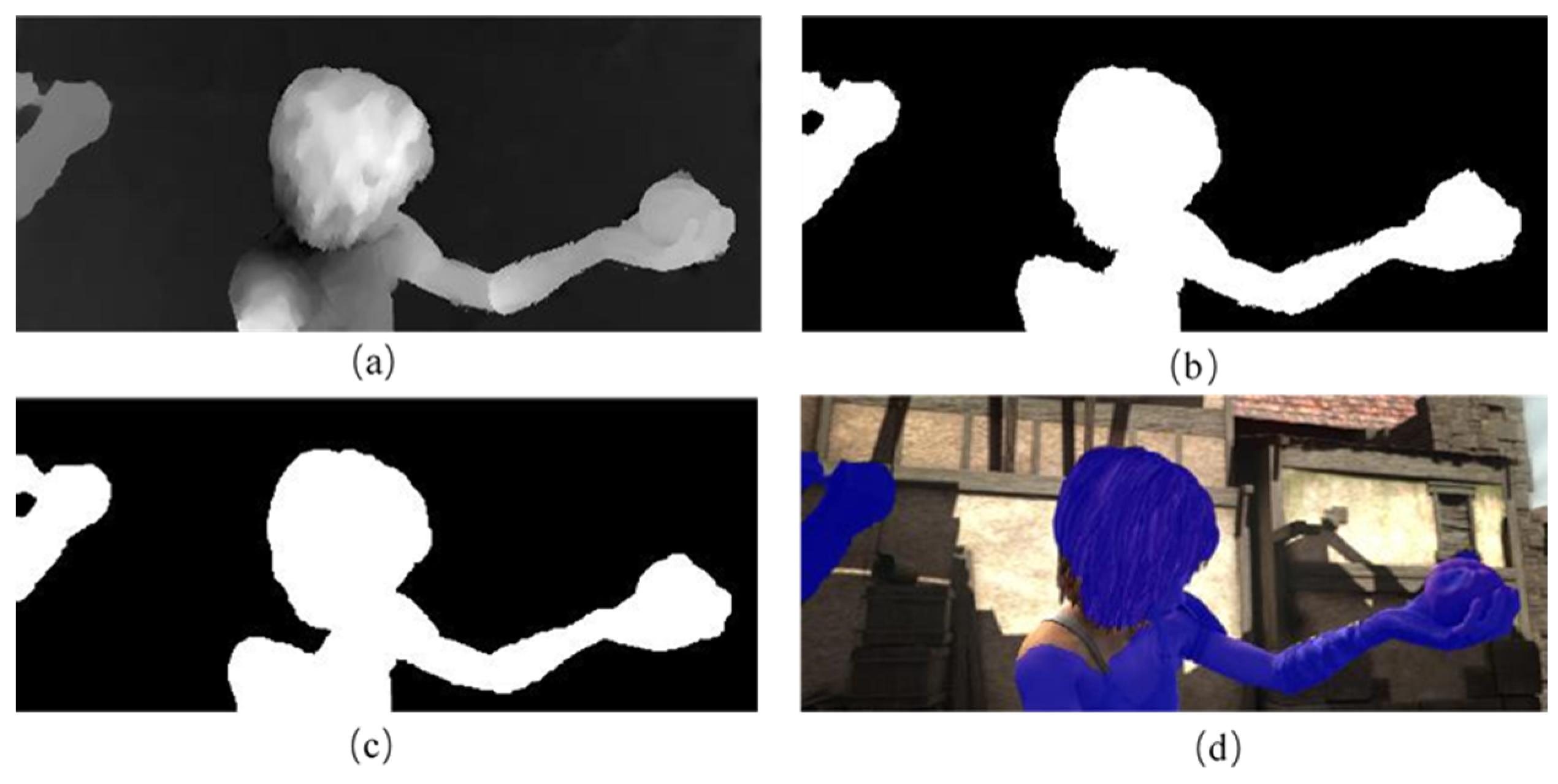
3.2. Experiment and Analysis

Figure 6 shows the comparison of optical flow estimation. The left to right sides depict the sequence images of Alley2, Ambush4, and Bamboo2 in the MPI Sintel Flow Final dataset, and the moving objects are all non-rigid. The up-to-down areas of Figure 6 represent the current frame image, the next frame image, the true optical flow of the current frame, and the optical flow field calculated by LK, HS pyramid, B&A, Brox optical flow estimation, and the improved optical flow calculation. The optical flow estimation results reveal that the sparse optical flow value obtained by the LK method cannot determine the complete optical flow of the moving object area; hence, it is tricky to extract the moving target area of the optical flow threshold. The optical flow in the background (Bamboo2) or the moving target area cannot be distinguished in the Bamboo2 sequence images. The HS pyramid method produces more blurred results at the images’ edges, and there is a false optical flow detection in the background area in the+ Ambush4 sequence images. The B&A method has a better optical flow estimation result in the edge area than the HS pyramid method. However, the optical flow estimation error is too large when the optical flow value of the non-rigid moving target area is quite different, such as in the Ambush4 sequence. The Brox algorithm has apparent errors. The proposed improved optical flow estimation algorithm exhibits a higher accuracy and better edge retention. The optical flow effect is also better when the optical flow values have large differences in the moving object area. In addition, the HS and LK optical flows were combined to deal with the problem of an optical flow calculation error in dynamic texture regions because of the optical flow estimation. There was no problem with optical flow error detection in the background area of Ambush4 when the environment was complex and had fog and snow. The optical flow detection effect of the moving target showing in Bamboo2 is also better when the domain occludes it.
Figure 7 illustrates the EPE and AAE comparisons of the optical flow estimated results in Figure 6. It also shows that the two indexes of the optical flow estimation algorithm in this paper are lower than other algorithms for different image sequences with a higher estimated optical flow accuracy.
Figure 8 displays the segmentation results of moving target extraction corresponding to the different optical flow field estimations of each image frame in Figure 6. The robust feature threshold segmentation method was compared with the Otsu threshold method to prove its effectiveness and applicability. This method was also performed on different optical flow estimation methods such as LK, B&A, HS pyramidal, Brox, and this study’s results. The findings proved that this study’s robust feature threshold segmentation method could be applied to different optical flow estimation algorithms. Figure 8 presents the Otsu threshold moving object extraction results and Figure 8 represents the results of this study’s robust Harris feature threshold moving object extraction. According to the LK optical flow thresholding segmentation results of three image sequences, neither Otsu nor the proposed algorithm is suitable for sparse optical flow thresholds to extract moving objects. In the Alley2 sequence, the Otsu and this study’s threshold method failed because of the error of the optical flow estimation by the Brox algorithm. Otsu can only extract a part of the moving object, but this study’s method achieved better extraction results. This is because the optical flow amplitude of the head of the moving object is quite different from the body part, and the optical flow is also generated in the background. The Otsu can only segment a part of the foreground area with noticeable optical flow differences. This study’s optical flow estimation algorithm presented a higher accuracy and more accurate final extraction result. In the Bamboo2 sequence, the optical flow amplitude in the foreground area is significantly higher than in the background area due to the weak optical flow in the background area; hence, Otsu performs better in the Alley2 sequence. Because the optical flow amplitude of the moving target head region is significantly lower than other target regions, the Otsu fails to detect the head region completely in optical flow estimation results. In contrast, this study’s algorithm has a better segmentation. In the Bamboo2 sequence, some pieces of Bamboo2 are an occlusion obstacle as the background area generates optical flow, which should not be detected as the foreground area with the moving object, and the optical flow amplitude of the background area of the whole frame image is large. Those elements seriously interfere with the segmentation and extraction of the foreground area of the moving object. The threshold segmentation algorithm in this paper does not misinterpret the occlusion obstacle area in B&A and the enhanced optical flow estimation method presented in this study. In summary, the results of the robust feature threshold segmentation proposed in this study are significantly better than the commonly used Otsu threshold processing algorithm and more suitable than the Otsu threshold processing method for the HS pyramid, B&A, and Brox, which are commonly used optical flow estimation algorithms that can segment the moving target area more accurately in static or moving environments. Moreover, the enhanced optical flow estimation algorithms with the proposed robust feature threshold segmentation method in this study achieved better results.
Morphological image processing is required because many problems accompany the detected moving object foreground area. Figure 9 compares the morphological processing results of different optical flow algorithms with the proposed robust feature threshold segmentation method. The top-to-bottom regions of Figure 9 depict the current image, the real foreground area of the moving object, the morphological image operation of HS, B&A, Brox, and this study’s optical flow algorithm with threshold processing. The binary image of the foreground regions of the moving object extracted after morphological processing has no holes and irregular edges. The problem of small areas in the background area has also been addressed.
Figure 10 shows the performance test results of the moving object detection method obtained by the proposed algorithm and the HS pyramid, B&A, and Brox after thresholding and morphological operation processing in this paper. Figure 10a shows the accuracy rate. Figure 10b shows the recall rate. Figure 10c exhibits the all-around performance. The higher the value, the better the performance. Finally, the accuracy of the proposed algorithm is verified.

4. Conclusions

This paper proposes a robust feature threshold segmentation based on improved optical flow estimation to detect moving objects. Several experiments were conducted to prove the effectiveness of this study’s algorithm. This method exhibits obvious superiority compared with the representative methods based on optical flow as follows:
(1) The improved optical flow estimation method combined with HS and LK optical flow methods to reduce the effects of background noise and dynamic texture and improve the robustness and accuracy of optical flow estimation. Additionally, the Delaunay triangulation is introduced to reduce the inaccurate estimation of optical flow caused by the moving object ‘ghost’ problem. The algorithm can obtain high precision robust dense optical flow vector fields which can improve the accuracy and robustness of moving object detection.
(2) A robust feature threshold method was proposed, instead of the commonly used Otsu method, by extracting the feature points and calculating the affine transformation matrix of the background model. Then, the robust feature points were obtained which fulfilled the background model using the robust point optical flow value as a threshold to attract the moving object. Our robust feature threshold method can be used in both static and moving environments. Experimental results show that the threshold greatly improves the range of application scenes of moving object detection based on optical flow estimation.
Although this study has improved the moving object detection algorithm accuracy and application compared with the common moving object detection methods based on optical flow, there are still many aspects to be further studied. In the future, we will focus on the following research:
(1) This study did not identify different moving objects. Therefore, based on the research in this paper, using the motion optical flow information further, to conduct optical flow classification and moving behavior analysis, to achieve multi-objective detailed recognition will be the objective of future works.
(2) Robust feature threshold segmentation combined with an intensive optical flow estimation method based on deep learning will be considered as well as combining the Delaunay triangulation with the convolutional neural network to improve the efficiency of moving object detection in future work.

Author Contributions

Conceptualization, J.D., Z.Z. and Z.Y.; methodology, J.D.; validation, J.D., Z.Z. and X.Y.; data curation, J.D. and X.Z.; writing—original draft preparation, J.D.; writing—review and editing, J.D.; visualization, J.D.; supervision, Z.Y.; project administration, X.Y.; funding acquisition, J.D., X.Y. and Z.Z. All authors have read and agreed to the published version of the manuscript.

Funding

This research was funded by the Coal Industry Engineering Research Center of Mining Area Environmental and Disaster Cooperative Monitoring (Anhui University of Science and Technology) (Grant NO. KSXTJC202205), Major science and technology projects of Anhui Province (Grant NO. 202103a05020026), Key Research and Development Program of Anhui Province (Grant NO. 202104a07020014), Major Project on Natural Science Foundation of Universities in Anhui Province (Grant NO. 2022AH040111), Anhui University of Science and Technology Talent Introduction Research Start-up (Grant NO. 2022yjrc96), and Natural Science Foundation Project of Anhui Province (Grant NO. 2008085MD114).

Institutional Review Board Statement

Not applicable.

Informed Consent Statement

Not applicable.

Data Availability Statement

Publicly available datasets were analyzed in this study. This data can be found here: http://sintel.is.tue.mpg.de/downloads (accessed on 8 April 2023).

Acknowledgments

We want to express our sincere gratitude to the anonymous reviewers and editors for their efforts in the improvement of the paper.

Conflicts of Interest

The authors declare no conflict of interest.

References

  1. Kulchandani, J.S.; Dangarwala, K.J. Moving object detection: Review of recent research trends. In Proceedings of the 2015 International Conference on Pervasive Computing (ICPC), Pune, India, 8–10 January 2015; pp. 1–5. [Google Scholar]
  2. Zhan, C.; Duan, X.; Xu, S.; Song, Z.; Luo, M. An Improved Moving Object Detection Algorithm Based on Frame Difference and Edge Detection. In Proceedings of the Fourth International Conference on Image and Graphics (ICIG 2007), Chengdu, China, 22–24 August 2007; pp. 519–523. [Google Scholar]
  3. Chapel, M.-N.; Bouwmans, T. Moving objects detection with a moving camera: A comprehensive review. Comput. Sci. Rev. 2020, 38, 100310. [Google Scholar] [CrossRef]
  4. Yazdi, M.; Bouwmans, T. New trends on moving object detection in video images captured by a moving camera: A survey. Comput. Sci. Rev. 2018, 28, 157–177. [Google Scholar] [CrossRef]
  5. Stojnić, V.; Risojević, V.; Muštra, M.; Jovanović, V.; Filipi, J.; Kezić, N.; Babić, Z. A Method for Detection of Small Moving Objects in UAV Videos. Remote Sens. 2021, 13, 653. [Google Scholar] [CrossRef]
  6. Singla, N. Motion detection based on frame difference method. Int. J. Inf. Comput. Technol. 2014, 4, 1559–1565. [Google Scholar]
  7. Shaikh, S.H.; Saeed, K.; Chaki, N. Moving Object Detection Using Background Subtraction. In Moving Object Detection Using Background Subtraction; Springer: Cham, Switzerland, 2014; pp. 15–23. [Google Scholar] [CrossRef]
  8. Yin, Z.; Shi, J. GeoNet: Unsupervised Learning of Dense Depth, Optical Flow and Camera Pose. In Proceedings of the 2018 IEEE/CVF Conference on Computer Vision and Pattern Recognition, Salt Lake, UT, USA, 18–12 June 2018; pp. 1983–1992. [Google Scholar]
  9. Saddique, M.; Asghar, K.; Bajwa, U.I.; Hussain, M.; Habib, Z. Spatial Video Forgery Detection and Localization using Texture Analysis of Consecutive Frames. Adv. Electr. Comput. Eng. 2019, 19, 97–108. [Google Scholar] [CrossRef]
  10. Sengar, S.S.; Mukhopadhyay, S. Moving object detection based on frame difference and W4. Signal Image Video Process. 2017, 11, 1357–1364. [Google Scholar] [CrossRef]
  11. Sengar, S.S.; Mukhopadhyay, S. A novel method for moving object detection based on block based frame differencing. In Proceedings of the 2016 3rd International Conference on Recent Advances in Information Technology (RAIT), Dhanbad, India, 3–5 March 2016; pp. 467–472. [Google Scholar]
  12. Kalli, S.; Suresh, T.; Prasanth, A.; Muthumanickam, T.; Mohanram, K. An effective motion object detection using adaptive background modeling mechanism in video surveillance system. J. Intell. Fuzzy Syst. 2021, 41, 1777–1789. [Google Scholar] [CrossRef]
  13. Suresh, D.S.; Lavanya, M.P. Motion Detection and Tracking using Background Subtraction and Consecutive Frames Difference Method. Int. J. Res. Stud. Sci. Eng. Technol. 2014, 1, 16–22. [Google Scholar]
  14. Piccardi, M. Background subtraction techniques: A review. In Proceedings of the 2004 IEEE International Conference on Systems, Man and Cybernetics (IEEE Cat. No.04CH37583), The Hague, The Netherlands, 10–13 October 2004; pp. 3099–3104. [Google Scholar]
  15. Agarwal, A.; Gupta, S.; Singh, D.K. Review of optical flow technique for moving object detection. In Proceedings of the 2016 2nd International Conference on Contemporary Computing and Informatics (IC3I), Greater Noida, India, 14–17 December 2016; pp. 409–413. [Google Scholar]
  16. Sengar, S.S.; Mukhopadhyay, S. Detection of moving objects based on enhancement of optical flow. Optik 2017, 145, 130–141. [Google Scholar] [CrossRef]
  17. Cho, J.; Jung, Y.; Kim, D.S.; Lee, S.; Jung, Y. Moving Object Detection Based on Optical Flow Estimation and a Gaussian Mixture Model for Advanced Driver Assistance Systems. Sensors 2019, 19, 3217. [Google Scholar] [CrossRef] [Green Version]
  18. Bors, A.G.; Pitas, I. Optical flow estimation and moving object segmentation based on median radial basis function network. IEEE Trans. Image Process. 1998, 7, 693–702. [Google Scholar] [CrossRef] [Green Version]
  19. GaliC, S.; LonCariC, S. Spatio-temporal image segmentation using optical flow and clustering algorithm. In Proceedings of the IWISPA 2000, Proceedings of the First International Workshop on Image and Signal Processing and Analysis in Conjunction with 22nd International Conference on Information Technology Interfaces, Pula, Croatia, 14–15 June 2000; IEEE: Piscataway, NJ, USA; pp. 63–68. [Google Scholar]
  20. Wei, S.-G.; Yang, L.; Chen, Z.; Liu, Z.-F. Motion Detection Based on Optical Flow and Self-adaptive Threshold Segmentation. Procedia Eng. 2011, 15, 3471–3476. [Google Scholar] [CrossRef] [Green Version]
  21. Yu, X.; Chen, X.; Jiang, M. Detection of Moving Object in Moving Background Based on Feature Vector Field Fuzzy Segmentation and OTSU Method. Opto-Electron. Eng. 2012, 39, 94–102. [Google Scholar] [CrossRef]
  22. Han, X.; Gao, Y.; Lu, Z.; Zhang, Z.; Niu, D. Research on Moving Object Detection Algorithm Based on Improved Three Frame Difference Method and Optical Flow. In Proceedings of the 2015 Fifth International Conference on Instrumentation and Measurement, Computer, Communication and Control (IMCCC), Qinhuangdao, China, 18–20 September 2015; pp. 580–584. [Google Scholar]
  23. Mendes, P.A.; Mendes, M.; Coimbra, A.P.; Crisóstomo, M.M. Movement detection and moving object distinction based on optical flow. In Proceedings of the Lecture Notes in Engineering and Computer Science: Proceedings of The World Congress on Engineering, London, UK, 3–5 July 2019; pp. 3–5. [Google Scholar]
  24. Mendes, P.A.; Paulo Coimbra, A. Movement Detection and Moving Object Distinction Based on Optical Flow for a Surveillance System. In Transactions on Engineering Technologies; Ao, S.I., Gelman, L., Kim, H.K., Eds.; Springer: Singapore, 2021; pp. 143–158. [Google Scholar] [CrossRef]
  25. Han, P.; Du, J.; Zhou, J.; Zhu, S. An Object Detection Method Using Wavelet Optical Flow and Hybrid Linear-Nonlinear Classifier. Math. Probl. Eng. 2013, 2013, 965419. [Google Scholar] [CrossRef]
  26. Sun, W.; Sun, M.; Zhang, X.; Li, M. Moving Vehicle Detection and Tracking Based on Optical Flow Method and Immune Particle Filter under Complex Transportation Environments. Complexity 2020, 2020, 3805320. [Google Scholar] [CrossRef]
  27. Fleet, D.J.; Weiss, Y. Optical Flow Estimation. In Handbook of Mathematical Models in Computer Vision; Springer: New York, NY, USA, 2006; pp. 237–257. [Google Scholar] [CrossRef]
  28. Brox, T.; Bruhn, A.E.; Papenberg, N.; Weickert, J. High Accuracy Optical Flow Estimation Based on a Theory for Warping. In Proceedings of the 8th European Conference on Computer Vision, Berlin/Heidelberg, Germany, 11–14 May 2004; pp. 25–36. [Google Scholar]
  29. Chetverikov, D.; Fazekas, S.; Haindl, M. Dynamic texture as foreground and background. Mach. Vis. Appl. 2010, 22, 741–750. [Google Scholar] [CrossRef]
  30. Monzón, N.; Salgado, A.; Sánchez, J. Regularization strategies for discontinuity-preserving optical flow methods. IEEE Trans. Image Process. 2016, 25, 1580–1591. [Google Scholar] [CrossRef] [Green Version]
  31. Kennedy, R.; Taylor, C.J. Optical flow with geometric occlusion estimation and fusion of multiple frames. In Proceedings of International Workshop on Energy Minimization Methods in Computer Vision and Pattern Recognition; Springer: Cham, Switzerland, 2015; pp. 364–377. [Google Scholar]
  32. Zhang, C.; Chen, Z.; Wang, M.; Li, M.; Jiang, S. Motion Occlusion Detecting from Image Sequence Based on Optical Flow and Delaunay Triangulation. Acta Electron. Sin. 2018, 46, 479–485. [Google Scholar]
  33. Negahban, S.N.; Ravikumar, P.; Wainwright, M.J.; Yu, B. A Unified Framework for High-Dimensional Analysis of $M$-Estimators with Decomposable Regularizers. Stat. Sci. 2012, 27, 538–557. [Google Scholar] [CrossRef] [Green Version]
  34. Rosten, E.; Drummond, T. Fusing Points and Lines for High Performance Tracking. In Proceedings of the Tenth IEEE International Conference on Computer Vision (ICCV’05), Beijing, China, 17–20 October 2005; pp. 1508–1515. [Google Scholar]
  35. Bay, H.; Tuytelaars, T.; Van Gool, L. SURF: Speeded up robust features. In Proceedings of Proceedings of the 9th European Conference on Computer Vision (ECCV), Graz, Austria, 7–13 May 2006; pp. 404–417. [Google Scholar]
  36. Harris, C.G.; Stephens, M. A Combined Corner and Edge Detector. In Proceedings of the Alvey Vision Conference, Manchester, UK, 31 August–2 September 1988; pp. 23.21–23.26. [Google Scholar]
  37. Butler, D.J.; Wulff, J.; Stanley, G.B.; Black, M.J. A naturalistic open source movie for optical flow evaluation. In Proceedings of the European Conference on Computer Vision (ECCV), Berlin/Heidelberg, Germany, 7 October 2012; pp. 611–625. [Google Scholar]
  38. Lucas, B.D.; Kanade, T. An Iterative Image Registration Technique with an Application to Stereo Vision. In Proceedings of the IJCAI’81: 7th International Joint Conference on Artificial Intelligence, Vancouver, BC, Canada, 24–28 August 1981; pp. 674–679. [Google Scholar]
  39. Hartley, R. Segmentation of optical flow fields by pyramid linking. Pattern Recognit. Lett. 1985, 3, 253–262. [Google Scholar] [CrossRef]
  40. Black, M.J.; Anandan, P. A framework for the robust estimation of optical flow. In Proceedings of the 1993 (4th) International Conference on Computer Vision, Berlin, Germany, 11–14 May 1993; pp. 231–236. [Google Scholar]
  41. Brox, T.; Malik, J. Large displacement optical flow: Descriptor matching in variational motion estimation. IEEE Trans. Pattern Anal. Mach. Intell. 2011, 33, 500–513. [Google Scholar] [CrossRef] [PubMed]
  42. Min, Q.; Huang, Y. Motion detection using binocular image flow in dynamic scenes. EURASIP J. Adv. Signal Process. 2016, 2016, 49. [Google Scholar] [CrossRef] [Green Version]
Figure 1. The framework of the algorithm for detecting moving objects with advanced estimated optical flow robust feature threshold segmentation. (a) is the optical flow estimation patch, (b) is the moving object detection patch.
Applsci 13 04854 g001
Figure 2. The occlusion problems in moving object detection.
Applsci 13 04854 g002
Figure 3. Optical flow estimation diagram based on motion occlusion determination. (a) The current image, (b) the ground optical flow value, (c) the optical flow vector estimation value without occlusion determination, and (d) the optical flow vector estimation after the occlusion removal value.
Applsci 13 04854 g003
Figure 4. Comparison of different feature points extraction and their corresponding robust feature points results. (a) Current image, (b) next image, (c) FAST feature points, (d) robust and FAST feature points, (e) SURF feature points, (f) robust SURF feature points, (g) Harris feature points, and (h) robust Harris feature points. The green points in the figure are matching points, and the red dots in figures (d,f) are the error detection points.
Applsci 13 04854 g004
Figure 5. The normalization of the image optical flow field and extraction of moving object foreground region. (a) Grey image of the optical flow, (b) binary image of robust Harris feature points thresholding, (c) binary image after morphological processing, and (d) mask of the target area.
Applsci 13 04854 g005
Figure 6. Comparison results of optical flow estimation in a single moving target scene. From left to right are the Alley2, Ambush4, and Bamboos2 datasets. The top-to-bottom areas show the current image, the next image, ground flow results, LK results, HS results, B&A results, Brox results, and this study’s results.
Applsci 13 04854 g006
Figure 7. Error comparison of optical flow estimation algorithms. (a) is the EPE comparison result and (b) is the AAE comparison result.
Applsci 13 04854 g007
Figure 8. Comparison of the extraction results in a single moving target scene. (I) Otsu results and (II) our thresholding results. The top-to-bottom regions depict the LK result, HS result, B&A result, Brox result, and this study’s result.
Applsci 13 04854 g008
Figure 9. Comparison of the HS pyramid, B&A, Brox, and the optical flow method with this study’s thresholding method and morphological operation results. The top-to-bottom regions present the current image, true moving target areas, HS result, B&A result, Brox result, and this study’s results.
Applsci 13 04854 g009
Figure 10. Performance comparison of moving object detection algorithms. (a) is the accuracy rate comparison result. (b) is the recall rate comparison result. (c) is the F-measure rate comparison result.
Applsci 13 04854 g010
Disclaimer/Publisher’s Note: The statements, opinions and data contained in all publications are solely those of the individual author(s) and contributor(s) and not of MDPI and/or the editor(s). MDPI and/or the editor(s) disclaim responsibility for any injury to people or property resulting from any ideas, methods, instructions or products referred to in the content.

