Abstract
Instantaneous friction and wear energy density are important indicators of the friction and wear state of the tooth flank of the milling cutter. Existing methods for identifying the friction and wear on the tooth flank of milling cutters mainly focus on the overall level of friction energy consumption and the maximum width of the accumulated wear on the teeth flanks, ignoring the unevenness and variability of the friction energy consumption and wear volume distribution of the tool flank, and the dynamic relationship between the instantaneous friction and wear on each tooth flank of the milling cutter is to be revealed. Transient cutting position of a high feed milling cutter tooth under milling vibration, and the use of the micro-element method to construct a model for solving the transient wear volume on the tool flank. A method of transient friction energy consumption on the cutter flank was proposed. The variation property of the instantaneous friction and wear energy density on the flank was exposed. The identification method of the variation property of the energy density was proposed according to different analysis results of the distribution of friction and wear energy density and verified by experiments. The outcomes indicated the maximum and mean of the energy density at different positions on the flank had a high similarity with the wear depth distribution on the flank. Using this method, the influence property of the friction and wear state and the cutting parameters under the milling vibration of the milling cutter tooth can be identified.
1. Introduction
During the cutting process of high-feed milling cutters, the friction and wear on the tooth flank shows a non-linear variation due to vibration and cutter tooth errors [1], which directly affects the milling cutter’s service life and quality of the processed surface. Studying the instantaneous wear depth, instantaneous wear volume, and dynamic relationship between the friction energy consumption on the tooth flank [2,3] and obtaining the property of the instantaneous wear distribution on the tool flank is of guiding significance to reveal the formation and evolution of the wear process on the tool flank of the high-feed milling cutter.
Recently, in the study of wear on the tooth flank of the milling cutter, Lv described the cutter’s wear mechanism experimentally using SEM and EDS [4]; Kıvak investigated the work of the cutter geometry angle, milling speed, and feed rate of the flank wear, respectively [5,6,7]; Li obtained a model of incremental wear of the tool flank of the tool under five factors based on orthogonal experiments [8]; Su constructed the wear curves of different types of cutters and predicted the wear states and validated them by experiments [9]; Zhang improved the precision of the tool’s wear estimation by constructing a dual compensational strategy based on a multi-model support vector regression [10]; Liu et al. analyzed and modeled the milling cutter’s wear and proposed a milling cutter wear monitoring system, which has an online measurement of the milling force and milling temperature [11]; Zhang used the cutting force model and a wavelet analysis to develop a multilayer perceptron to estimate the milling tool’s wear [12]. The above research results are of great significance in guiding the construction of the instantaneous wear volume model of the tool flank of the milling cutter. However, it is crucial to deeply establish a study on the effect of tooth error and milling vibration on the friction and wear process on the tooth flank, which is ignored.
The formation and evolution process of wear on the tool flank of high-efficiency milling cutters is closely related to instantaneous friction energy consumption at tool–workpiece interface. Gowthaman used a cutting energy prediction model to reveal the work of the milling speed, the thickness of non-formed chips, and the tool angle of the cutting energy consumption [13,14,15]. Shi et al. established a novel milling power-based energy consumption model for milling cutters and investigated the correlation between the machine tool energy consumption and milling cutter friction wear [16]; Choudhury et al. used the relationship between the wear of the tooth flank and average tangential milling force coefficient to estimate the energy consumption for tool wear [17]. Some scholars proposed a prediction method for the SEC of machine tools considering tool wear evolution and established a prediction model by a support vector regression algorithm [18]. Baumann effectively reduced the cutting energy consumption by improving the friction behavior between the cutter–workpiece interface [19]; Dou developed a grinding force model considering tool wear and an energy consumption estimation model for tool tooth flank wear and used a time series analysis method to achieve the prediction of the flank wear [20].
This paper developed a model for solving the instantaneous wear volume and instantaneous friction characteristic variables on the flank of the cutter based on the study of the instantaneous position and instantaneous cutter contact relationships under the milling vibration and cutter tooth error. A method to identify the instantaneous friction and wear energy density distribution property of the cutter flank was proposed. The instantaneous friction and wear process of the milling cutter was exposed. The experimental verification and analysis of the loss response characteristics of the friction and wear of the cutter flank were carried out.
2. Instantaneous Wear Volume Model of the Tooth Flank
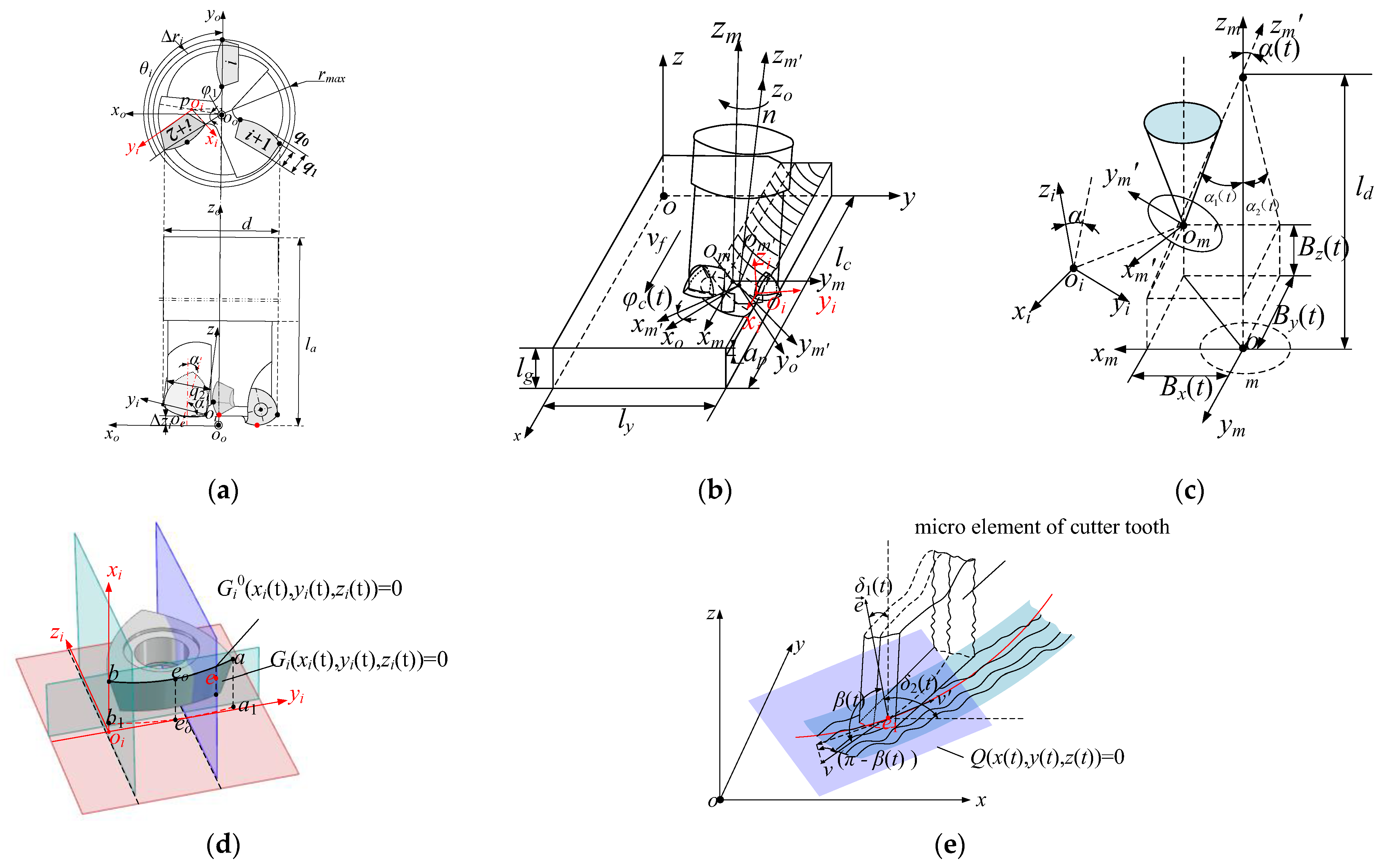
Under the action of the tool tooth error and vibration, the transient cutting contact relationship between the high-feed milling cutter and its cutter tooth and workpiece is in an unsteady state, as shown in Figure 1. The micro-elements of the tooth involved in milling at any position and their instantaneous poses are shown in Figure 2. Among them, the explanations of the variables are shown in Table 1.

Figure 1.
Structure of the tool and its transient cutting behavior: (a) cutter structure; (b) instantaneous cutting behavior of cutter; (c) transient attitude angle of milling cutter; (d) cutter tooth micro-element interception; (e) micro-element instantaneous position of cutter tooth.
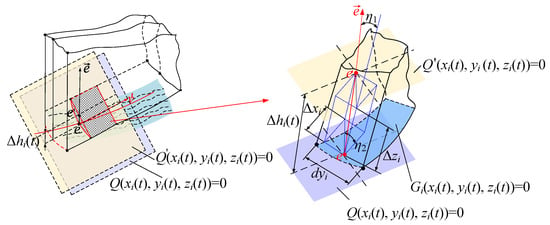
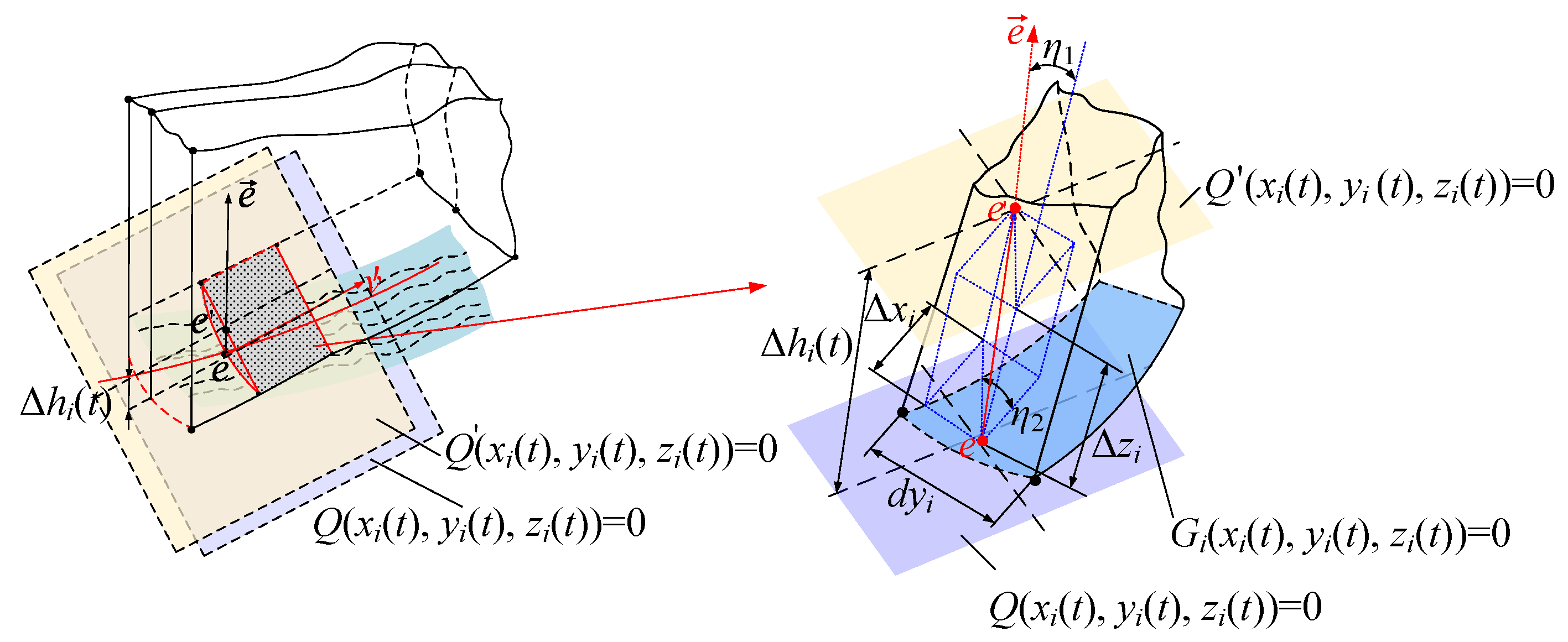
Figure 2.
Instantaneous wear depth of the tool flank after micro-element of cutter tooth.

Table 1.
Illustration of instantaneous milling process variables of high-feed milling cutter under vibration.
The transient position of obtained from the milling cutter structure, and its instantaneous cutting behavior in Figure 1 is shown in Equation (1):
Among them, the Gi is the cutter flank, and the Gi0 is the cutting edge.
In Equation (1), M is the transformation matrix from the cutter–tooth coordinate system to the workpiece coordinate system, the M1~M3 is the translation matrix of the tool tooth coordinate system to the coordinate system of the workpiece, and the T1~T5 is the rotating matrix from the tool tooth coordinate to the coordinate system of the workpiece.
From Figure 1 and Equation (1), the transient attitude angle of the micro-element of the cutter tooth in the workpiece coordinate system is:
The instantaneous friction contact point, e, between the cutter flank and the machined transition surface is:
where t − Δt is the moment when the cutting edge forms the machined transition surface.
The speed of the contact point in the three directions along the coordinate system of the workpiece is:
where (xe, ye, ze) is the coordinate of the friction contact point, e, along the feed, cutting width, and axial directions of the tool flank, respectively.
Using Equations (4) and (5), the angle β(t) between the normal vector of the common tangent at point e and the velocity of motion v(t) can be obtained, and the instantaneous friction velocity v′(t) at point e is:
From Figure 1, the instantaneous wear depth of the cutter’s face after the micro-element of the cutter tooth is shown in Figure 2, where e′ is the location point of point e on the tool flank after wear, η1 is the angle between the common tangent normal vector of point e and the zi axis space, and η2 is the angle between the projection of the common tangent normal vector of point e on the xioiyi coordinate plane and the xi axis plane.
From Figure 2, the instantaneous growth rate of the wear depth, vhi(t), and the instantaneous increment of the wear depth, Δhi(t), at the friction contact point, e, of the cutter flank after the micro-element of the cutter tooth are:
where hi(t) is the cumulative wear depth of the tooth flank as a function of time in the thermal coupling field of the cutter tooth.
From Figure 2 and Equation (7), the instantaneous coordinate increments Δxi(t) and Δzi(t) of point e′, with respect to point e along the xi and zi directions, can be derived, respectively:
From Equations (4), (7) and (8), the micro-element tool flank of the cutter tooth under the milling cutter’s wear conditions can be illustrated as:
From Equations (7)–(9), the curve formed by the point where the instantaneous wear depth on the tool flank is 0 is the lower boundary of transient friction wear on the tooth flank. Using Equations (1), (7) and (8), the Equations of the micro-element cutting edge under wear conditions could be obtained. Accordingly, the boundaries of the transient friction wear can be determined, as shown in Figure 3.
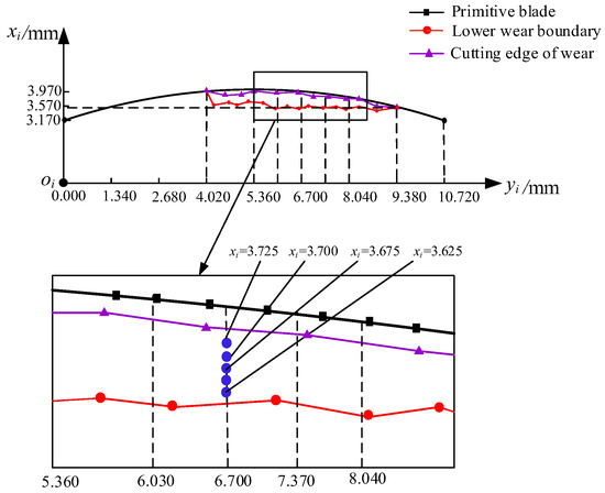
Figure 3.
Instantaneous wear boundary of cutter tooth 1.
From Equations (4)–(9), the instantaneous wear volume growth rate, Vi(t), and the accumulated wear volume, ΣVi, at the friction contact points within the friction wear boundaries are:
where si is the instantaneous friction area at point e, and L is the instantaneous friction area boundary.
3. Method for Solving Instantaneous Friction Wear and Energy Density on the Tooth Flank
From Figure 1 and Figure 2, the friction velocity and contact stress during the transient contact friction between the tool flank and the processed transition surface are shown in Figure 4.
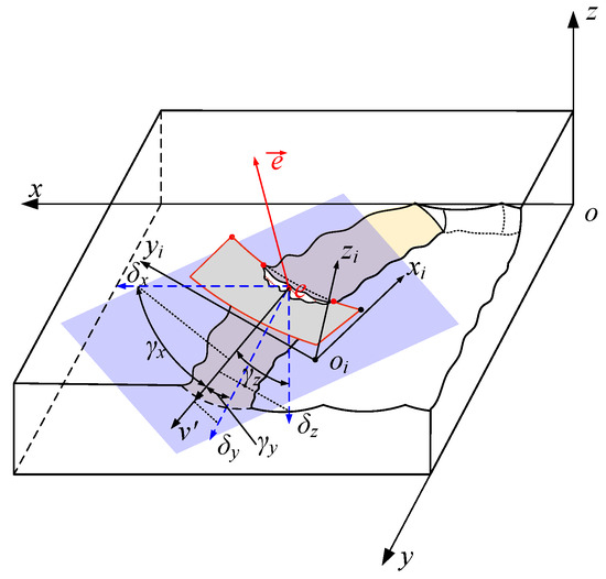
Figure 4.
Instantaneous friction velocity and friction force.
From Figure 4, stress components along the transient friction velocity direction of the micro-element on the tool flank are obtained using the instantaneous thermal coupling field equivalent force in the workpiece coordinate system:
where γx(t),γy(t),γz(t) are the angles between σx(t), σy(t), σz(t) and the friction velocity, respectively.
From Equations (7) and (11), the transient friction energy consumption, Pi(t), at any point on the cutter’s face after the micro-element of the tool flank and the cumulative friction energy consumption, ΣEi, are:
where tj, tj+1 are the cutting start time and cutting end time of the cutter teeth, respectively.
From Equations (11) and (12), the instantaneous friction wear energy density, ρi(t), at any point on the micro-element and the average friction wear energy density, , during the cutting period are:
where ΣVi is the total volume of wear at any point on the tool flank after the micro-element.
The above models could be used to solve for the instantaneous friction and wear energy density, in combination with the energy-efficient milling cutter and its cutting titanium alloy process conditions provided by the company. The milling method is dry-milling, the milling cutter is an indexable carbide milling cutter with a diameter of 32 mm, and the tooth error and processing parameters are listed in Table 2.
Table 2.
Experiment scheme 1.
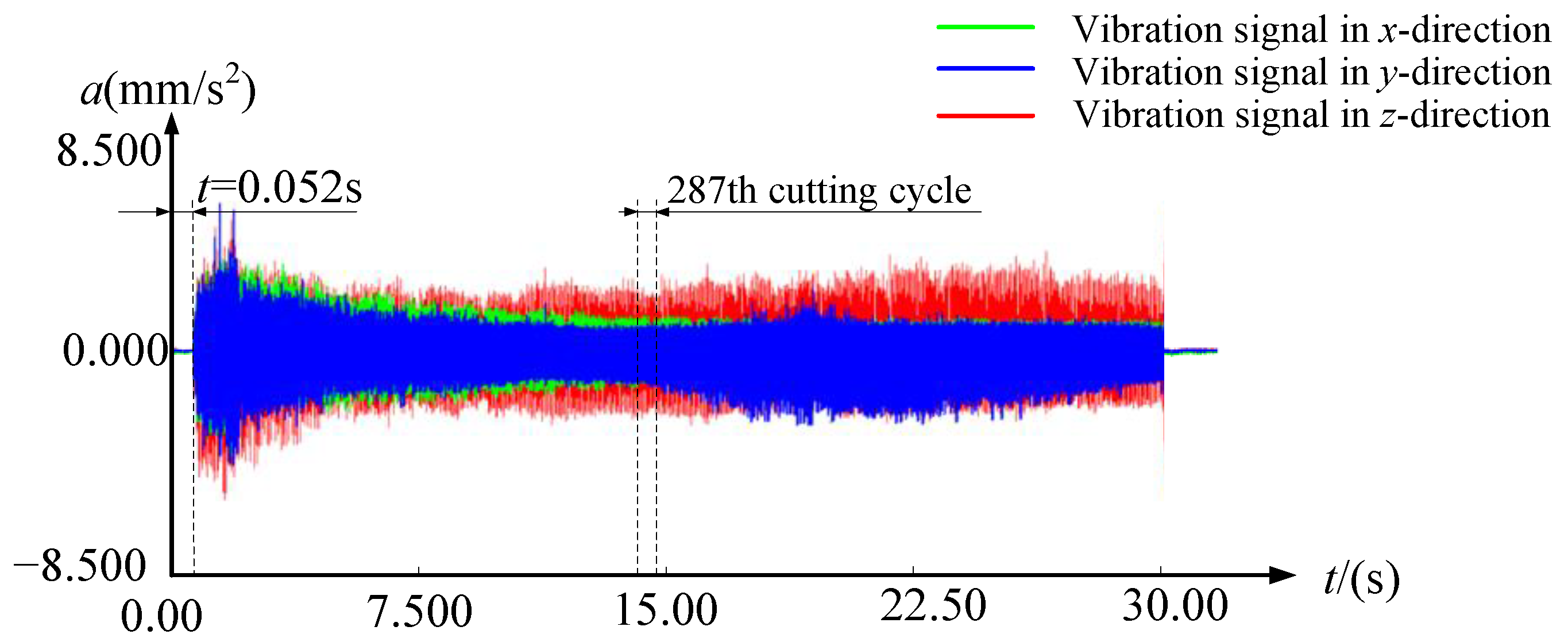
Using the above scheme, the vibration acceleration signals were obtained by the experiments, as shown in Figure 5.

Figure 5.
Experimental cutting vibration acceleration signals for scheme 1.
The milling tool model in Figure 1 and its transient cutting behavior solution method were used to analyze the thermal coupling field of cutting titanium alloy in combination with the experimental parameters in Table 1, where the thermal coupling field distribution of the first tooth of the above experimental milling cutter at the 287th cutting cycle with a contact angle of 45° is shown in Figure 6.
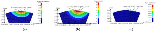
Figure 6.
Finite element stress field distribution of the tool flank: (a) equivalent effect distribution; (b) temperature distribution; (c) wear depth distribution.
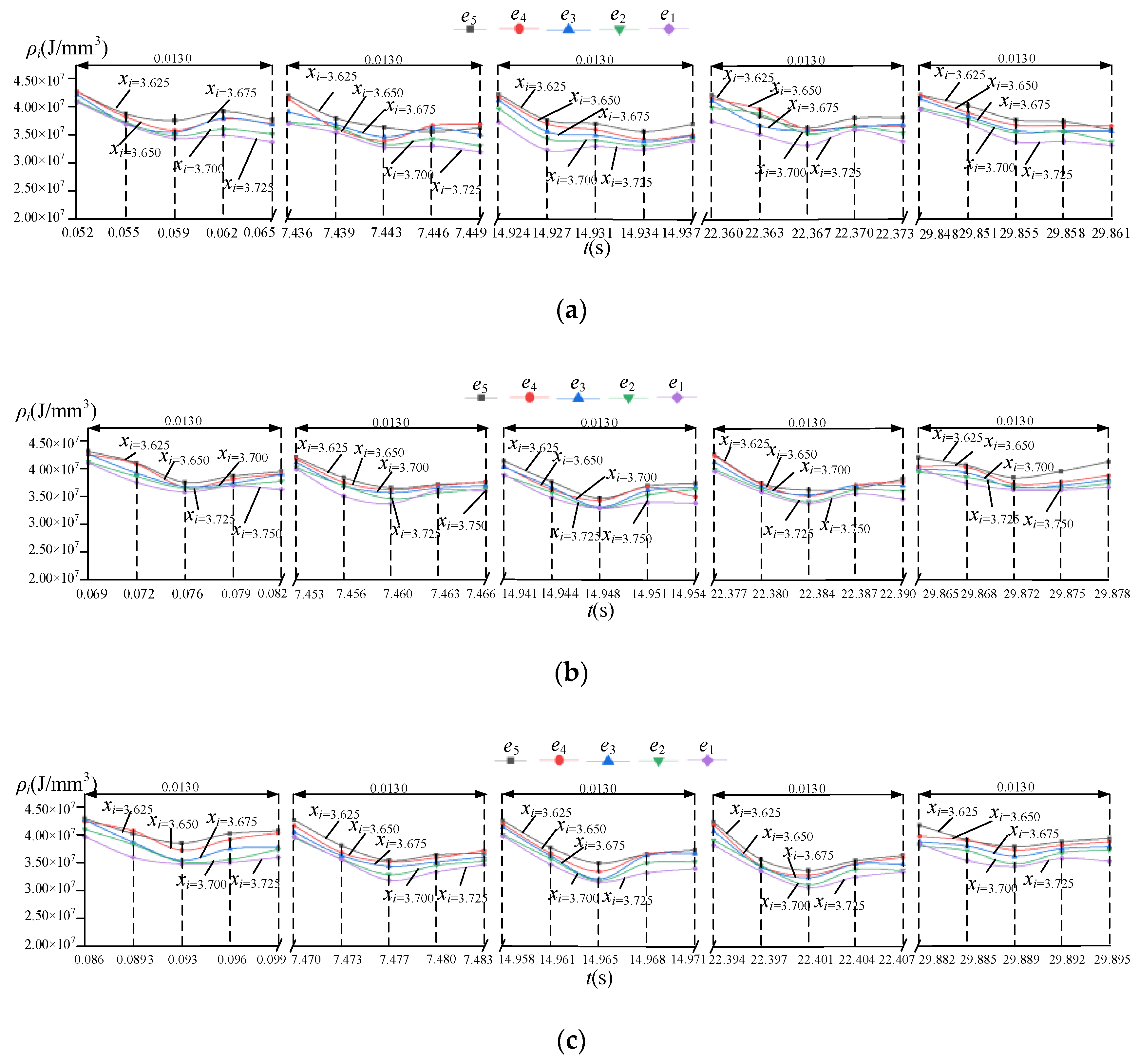
Based on Table 1 and Figure 5, Equation (13) is used to solve for the instantaneous friction and wear energy density, where the instantaneous friction and wear energy density on the flank of the three cutter teeth varies in the 1st milling cut cycle, the 143rd milling cut cycle, the 287th milling cut cycle, the 430th milling cut cycle, and the 574th milling cut cycle, as shown in Figure 7.
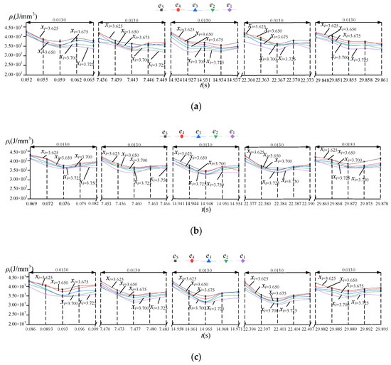
Figure 7.
Instantaneous friction wear energy density on the tool flank of scheme 1 (yi = 6.700 mm): (a) tooth 1; (b) tooth 2; (c) tooth 3.
In the figure, e1, e2, e3, e4, and e5 are the five characteristic points selected along the flank of the cutter tooth, whose xi and yi directional coordinates in the coordinate system of the cutter tooth are (3.635, 6.700), (3.650, 6.700), (3.675, 6.700), (3.700, 6.700), and (3.725, 6.700), respectively. It is 0.520~0.104s for the 1st cutting cycle, 7.436~7.488s for the 143rd cutting cycle, 14.924~14.976s for the 287th cutting cycle, 22.360~22.412s for the 430th cutting cycle, and 29.848~29.900s for the 574th cutting cycle.
From Figure 7, the friction wear energy density shows different variations at different positions on the tool flank of the three cutter teeth during the process of the cutting workpiece. The result shows that the transient conversion relationship between the friction energy of the flank face on the cutter tooth and the wear is unstable, and the dynamics of the friction wear of the flank face on the cutter tooth could be identified by using the above model’s method.
4. Variation of Friction and Wear Energy Density of the Tool Flank
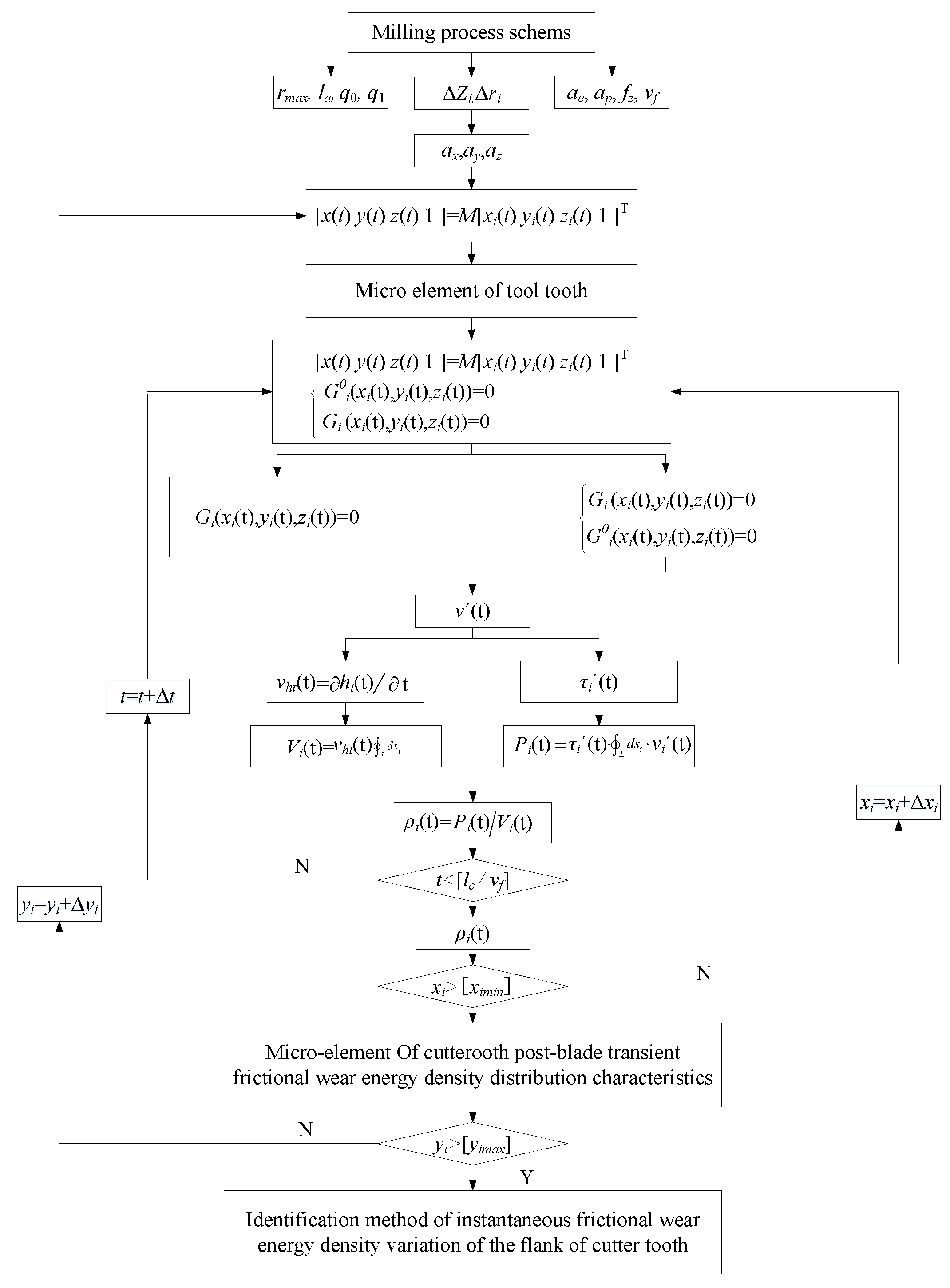
According to analysis results, the identification method of the instantaneous friction and wear energy density variation of the flank face on the cutter tooth was proposed, as shown in Figure 8.
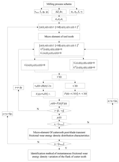
Figure 8.
Identification of friction and wear energy density variation on the tool flank.
The proposed identification method uses instantaneous cutting position changes under the action of the cutter tooth error and milling vibration. The results of a thermal coupling field analysis of the tool flank reveal the change process of the transient conversion relationship between friction energy and the wear of the tool flank, quantitative characterization of the diversity of the dynamic distribution of the friction and wear on the flank face, and evaluation of the milling process solution.
To verify the validity of the variation identification method of the friction and wear energy density on the flank face, we adopted the same milling cutter, workpiece, mounting method, cutting method, and testing method as scheme 1, kept the cutting depth and width unchanged, changed the error distribution of the cutter teeth by increasing the cutting speed to change the vibration, reduced the feed rate accordingly to keep cutting efficiency unchanged, conducted a milling vibration experiment, and solved the instantaneous friction and wear energy density on the flank face, as shown in Table 3.
Table 3.
Milling experiment, scheme 2.
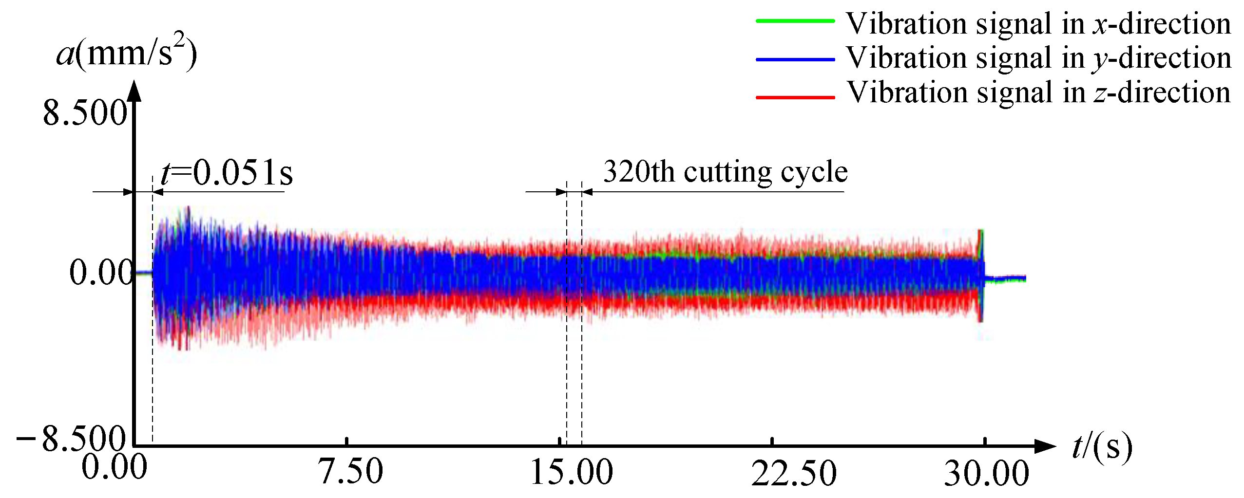
Using experimental scheme 2, the acquired acceleration signal under vibration is shown in Figure 9.
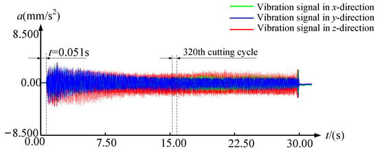
Figure 9.
Experimental cutting vibration acceleration signals for scheme 2.
Based on Table 3 and Figure 9, Equation (13) is used to solve for the instantaneous friction wear energy density of the tool flank, where the friction and wear energy density of the tool flank on the three cutter tooth varies in the first milling cut cycle, in the 160th milling cut cycle, in the 320th milling cut cycle, in the 480th milling cut cycle, and in the 640th milling cut cycle, as shown in Figure 10.
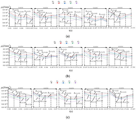
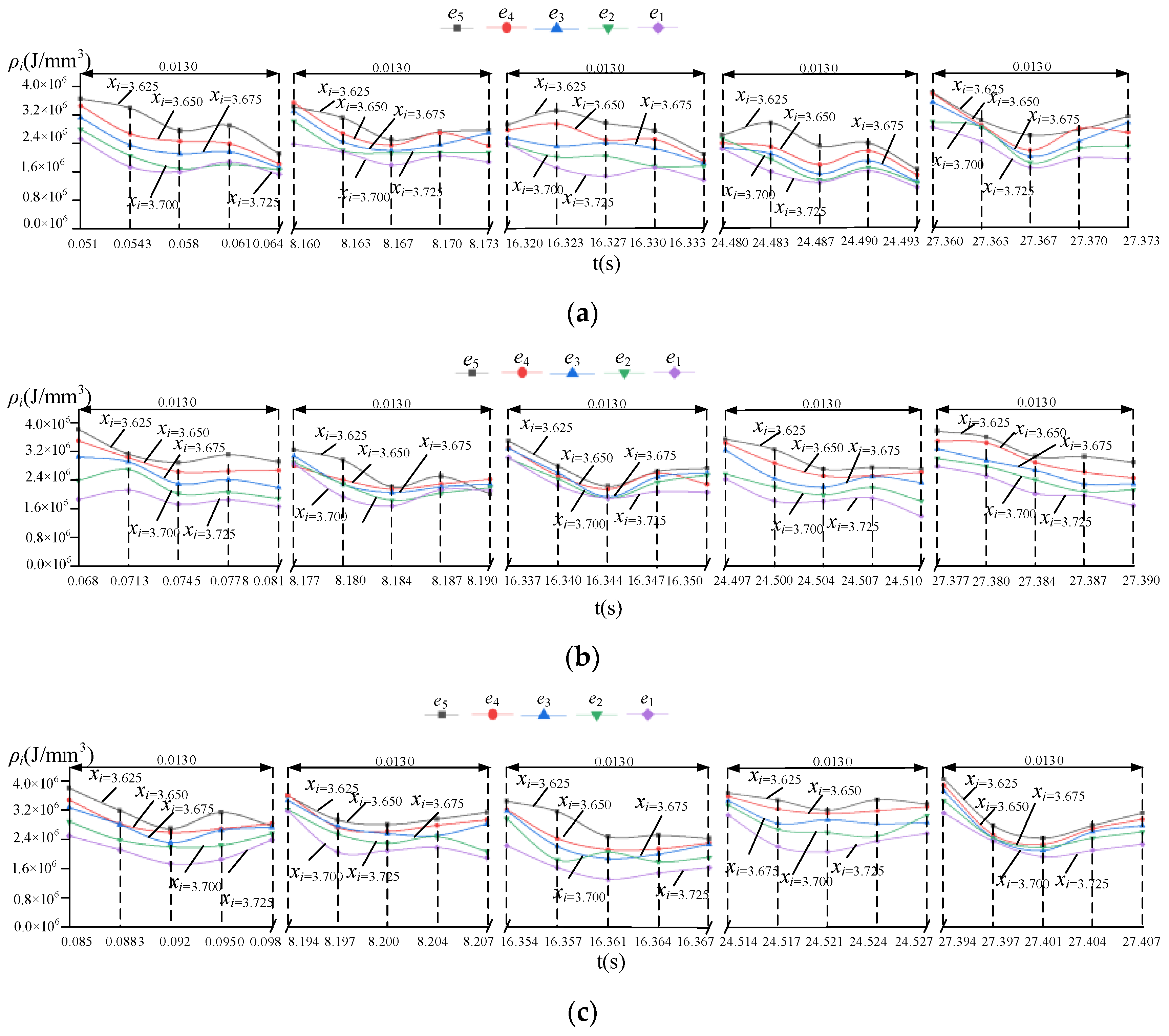
Figure 10.
Instantaneous friction and wear energy density on the tool flank of scheme 2 (yi = 6.700 mm): (a) tooth 1; (b) tooth 2; (c) tooth 3.
From Figure 10, e1, e2, e3, e4, and e5 are the five characteristic points selected along the flank of the cutter tooth, whose xi and yi directional coordinates in the coordinate system of the cutter tooth are (3.635, 6.700), (3.650, 6.700), (3.675, 6.700), (3.700, 6.700) and (3.725, 6.700), respectively. It is 0.051~0.102 s for the 1st cutting cycle, 8.160~8.211 s for the 160th cutting cycle, 16.320~16.371 s for the 320th cutting cycle, 24.480~24.531 s for the 480th cutting cycle, and 27.360~27.411 s for the 640th cutting cycle.
The mean, maximum, and total friction wear energy density of each characteristic point of the tool flank for one cutting cycle at multiple positions on the cutting edge under two scenarios were compared, where the comparison results of the two solutions for the intermediate cycle of the milling cutter are shown in Figure 11 and Figure 12. The cutting intermediate cycle for scheme 1 is the 287th cutting cycle, and the cutting intermediate cycle for scheme 2 is the 320th cutting cycle.
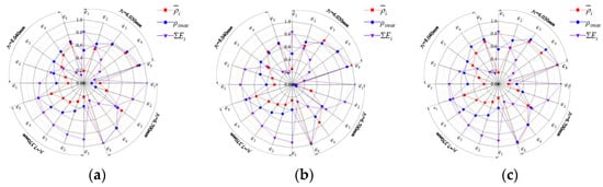
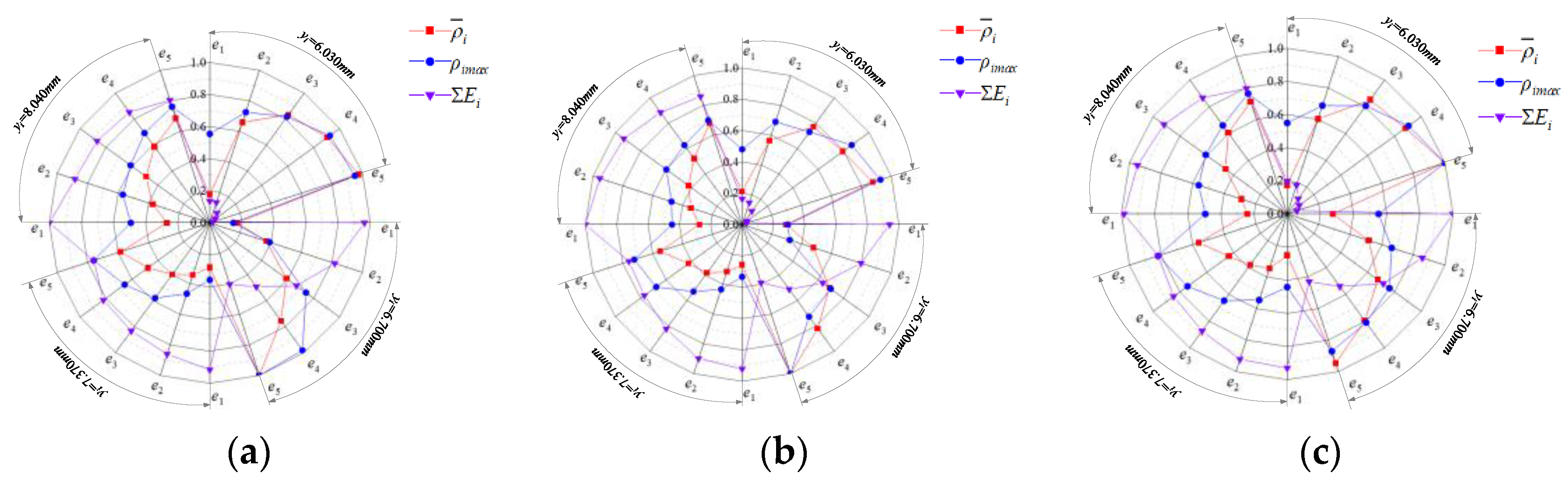
Figure 11.
Friction wear energy density distribution of three blades of scheme 1: (a) tooth 1; (b) tooth 2; (c) tooth 3.
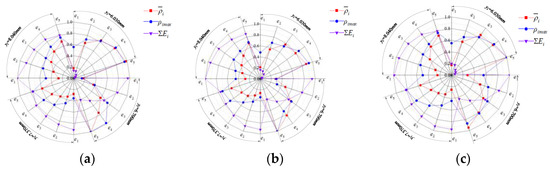
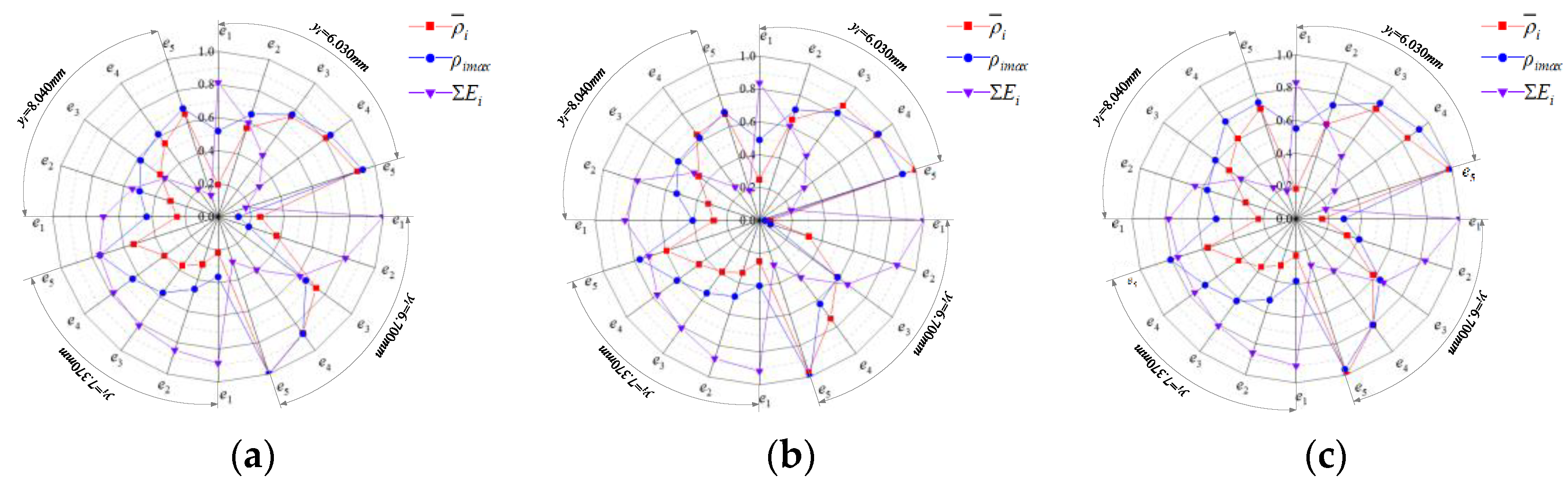
Figure 12.
Friction wear energy density distribution of three blades of scheme 2: (a) tooth 1; (b) tooth 2; (c) tooth 3.
From Figure 7, Figure 10, Figure 11, Figure 12, it can be seen that although the friction and wear energy density distribution curves on the flank face of the two schemes show similar changes, there are some differences among the cutter teeth, and they vary due to the change of the milling parameters, indicating that the model for solving the instantaneous friction and wear energy density on the flank face and the identification method are sensitive to changing cutting conditions.
5. Correlation Analysis between the Tool Flank Wear and Friction Wear Energy Density
The validity of above the model and method should be verified. The experimental results of the milling tool flank wear for scheme 1 and scheme 2 were detected by white light interferometer, as shown in Figure 13 and Figure 14.
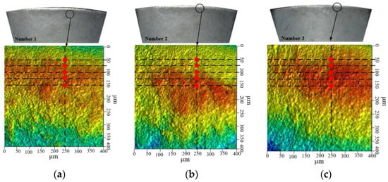
Figure 13.
Experimental results of the wear profile of three blades of scheme 1: (a) tooth 1; (b) tooth 2; (c) tooth 3.
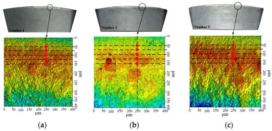
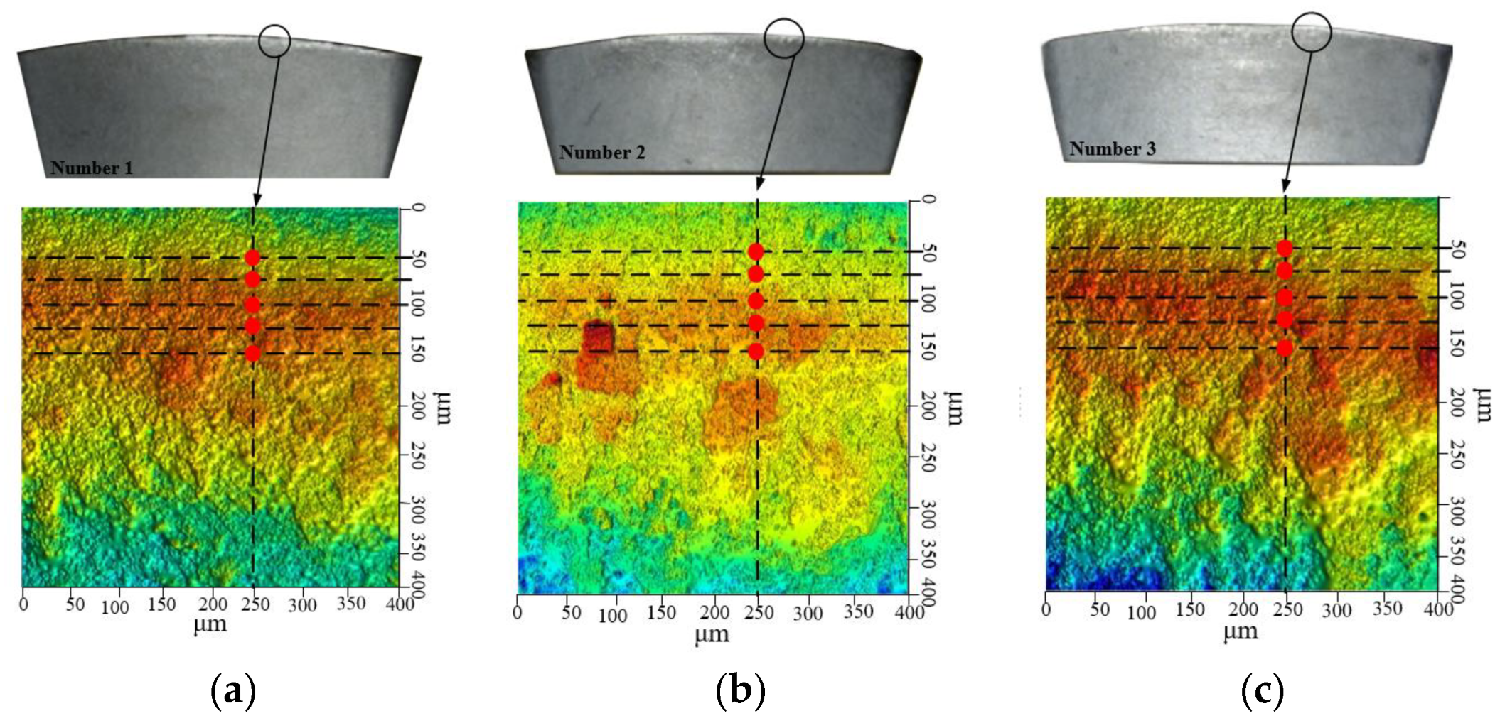
Figure 14.
Experimental results of the wear profile of three blades of scheme 2: (a) tooth 1; (b) tooth 2; (c) tooth 3.
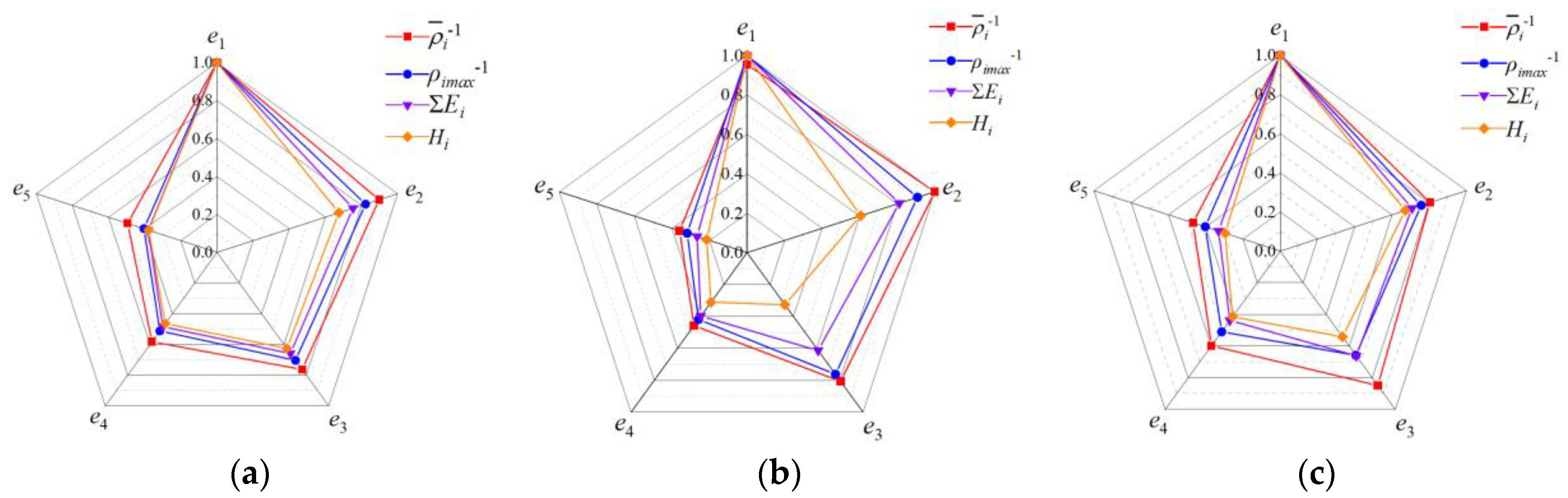
From Figure 13 and Figure 14, the accumulated wear depths at different locations on the flank of the cutter teeth are obtained; Equations (12) and (13) are used to solve the mean, maximum and minimum values of friction wear energy density and total friction energy at the corresponding position of each tool tooth during the process of milling the workpiece. These results of the comparative analysis of the accumulated wear depth and friction wear energy density for the two experimental schemes are shown in Figure 15 and Figure 16. Where, the greater the inverse of the mean and maximum values of friction wear energy density, the lower the wear resistance of the point and the more intense the degree of friction wear.
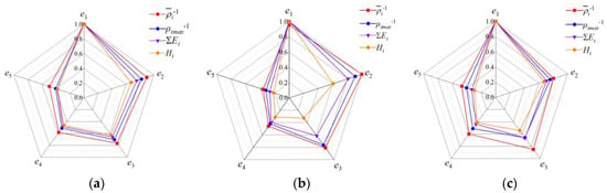
Figure 15.
Wear depth and friction wear energy density of three blades of scheme 1 (yi = 6.700 mm): (a) tooth 1; (b) tooth 2; (c) tooth 3.
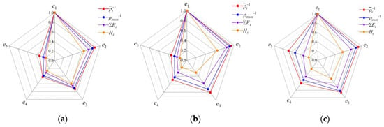
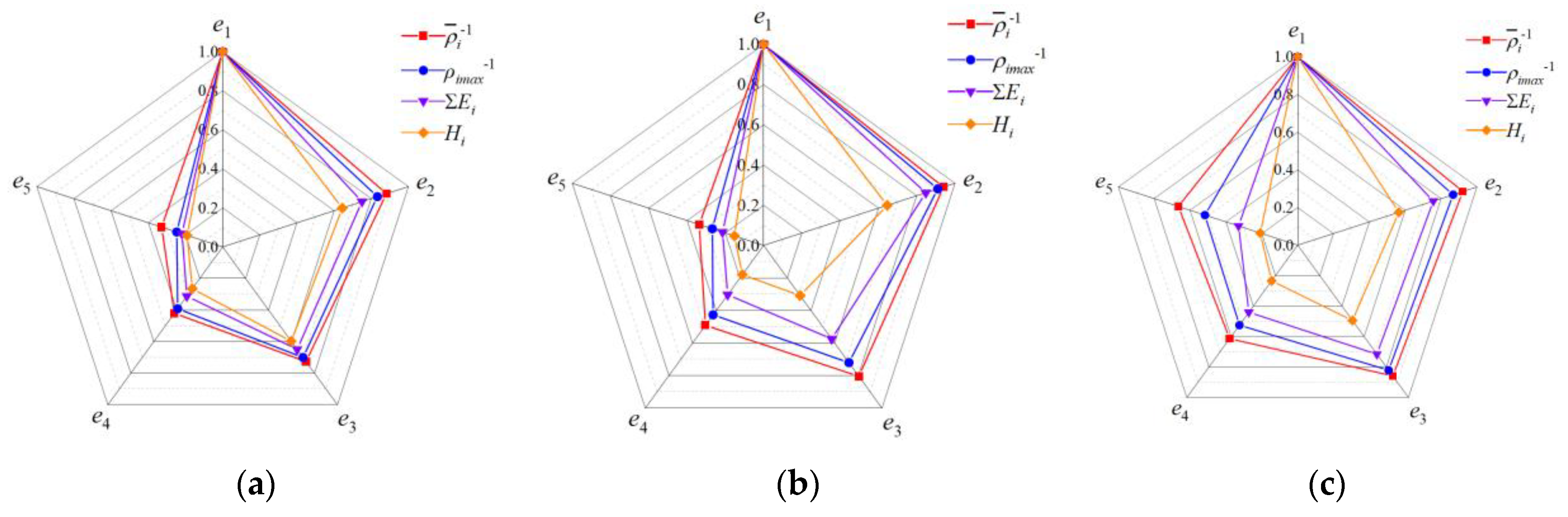
Figure 16.
Wear depth and friction wear energy density of three blades of scheme 2 (yi = 6.700 mm): (a) tooth 1; (b) tooth 2; (c) tooth 3.
To further verify the correctness of the friction and wear energy density solution model and the identification method of variation, the results of the friction and wear energy density solution on the flank face in Figure 15 and Figure 16 were used as the comparison sequence, and the accumulated wear depth measured results were used as the reference sequence, and an improved gray relative correlation analysis algorithm was used to analyze the accumulated wear depth and friction wear energy density obtained from the two experimental schemes, respectively; the results are shown in Table 4.
Table 4.
Correlation between cumulative wear depth and friction wear energy density.
In Table 4, the correlation of the accumulated wear depth between the two experiments are bigger than 0.860, and the correlation of the inverse maximum and mean value of the friction wear energy density between the two experiments are bigger than 0.790 and 0.740, respectively. It is shown that the friction and wear intensity of the flank face identified by using the solution results of the instantaneous friction and wear energy density model on the flank under different cutting conditions is in good agreement with the actual measured wear depth.
From the above results, the proposed model and method could realize the correct solution and identification of the response of the dynamic relationship between friction energy and flank wear under different process scheme conditions, and the influence of the friction wear process on the flank face by the milling parameters, cutter tooth error, and milling vibration could be effectively revealed.
6. Conclusions
- (1)
- A method for calculating the instantaneous pose on the flank face has been proposed. A calculation model of the instantaneous wear volume of the tool flank was established. The distribution and variation of the instantaneous wear volume of the cutter tooth’s flank face under milling vibration were revealed. The results show that the instantaneous wear depth and instantaneous wear volume on the flank face show unsteady variations with the contact angle and the cutting cycle, and there are obvious differences between different cutter teeth.
- (2)
- The instantaneous pose and instantaneous friction velocity and the instantaneous friction stress and instantaneous friction energy consumption model of the micro-element on the cutter tooth were established, and the distribution of instantaneous friction energy consumption on the flank face was revealed. The correlation analysis results showed that the correlation between the cumulative friction energy consumption of the tool flank and the experimental results of the wear depth was greater than 0.860. This model can be used to identify and reveal the friction and wear characteristics. The response property of the friction and wear of the flank face to change the structure and position was revealed.
- (3)
- An identification method for the instantaneous friction and wear energy density of the flank face has been proposed. The method revealed the difference in the dynamic relationship between the friction energy and wear on the flank of each cutter tooth of the milling cutter. The comparative analysis results of the process schemes showed that the method could be used to quantitatively characterize the diversity of the dynamic distribution of friction and wear on the flank face, and the milling process scheme can be evaluated accordingly.
Author Contributions
Conceptualization, B.J. and Q.N.; methodology, B.J. and P.Z.; software, S.S. and Q.M.; validation, P.Z. and Q.M.; investigation, Q.N; resources, B.J.; data curation, S.S. and Q.M.; writing—original draft preparation, Q.N.; writing—review and editing, Q.N. and B.J.; supervision, B.J. and P.Z.; project administration, B.J.; funding acquisition, B.J. All authors have read and agreed to the published version of the manuscript.
Funding
This research was funded by the Natural Science Foundation of the Heilongjiang Province of China, ZD2020E008, the National Natural Science Foundation of China: 52105440, and the National Natural Science Foundation of China, 51875145.
Institutional Review Board Statement
Not applicable.
Informed Consent Statement
Not applicable.
Conflicts of Interest
The authors declare no conflict of interest.
References
- Zhao, P.; Zhang, L.; Jiang, B. Instantaneous friction energy consumption and its evolution of high energy efficiency milling cutter. J. Adv. Mech. Eng. 2022, 14, 16878132221095917. [Google Scholar] [CrossRef]
- Younas, M. Development and Analysis of Tool Wear and Energy Consumption Maps for Turning of Titanium Alloy (Ti6Al4V). J. Manuf. Process. 2021, 62, 613–622. [Google Scholar] [CrossRef]
- Giorjão, R.A.R.; Avila, J.A.; Escobar, J.D. The study of volumetric wearing of PCBN/W-Re composite tool during friction stir processing of pipeline steels (X70) plates. J. Adv. Manuf. Technol. 2021, 114, 1555–1564. [Google Scholar] [CrossRef]
- Lv, D.; Wang, Y.; Yu, X. Effects of Cutting Edge Radius on Cutting Force, Tool Wear, and Life in Milling of SUS-316L Steel. J. Adv. Manuf. Technol. 2020, 111, 2833–2844. [Google Scholar] [CrossRef]
- Kıvak, T. Optimization of surface roughness and flank wear using the Taguchi method in milling of Hadfield steel with PVD and CVD coated inserts. J. Meas. 2014, 50, 19–28. [Google Scholar] [CrossRef]
- Guo, X.L.; Deng, M.S.; Wang, J.X. Effects of geometric angle and cutting speed on cutting forces and tool wear of ceramic cutting tools during peripheral up-milling of high-density fiberboard. J. Mater. Wiss. Und Werkst. 2020, 51, 461–468. [Google Scholar] [CrossRef]
- Nooraie, R.Y.; Safari, M.; Pak, A. Tool wear estimation in machining based on the flank wear inclination angle changes using the FE method. J. Mach. Sci. Technol. 2019, 24, 425–445. [Google Scholar] [CrossRef]
- Li, F.; Liu, J. Optimization of milling process parameters and prediction of abrasive wear rate increment based on cutting force experiment. J. Adv. Mech. Eng. 2021, 13, 16878140211039972. [Google Scholar] [CrossRef]
- Su, Y.; Li, C.; Zhao, G.; Li, C.; Zhao, G. Prediction models for specific energy consumption of machine tools and surface roughness based on cutting parameters and tool wear. J. Proc. Inst. Mech. Eng. Part B 2021, 235, 1225–1234. [Google Scholar] [CrossRef]
- Zhang, X.; Han, C.; Luo, M.; Zhang, D. Tool Wear Monitoring for Complex Part Milling Based on Deep Learning. Appl. Sci. 2020, 10, 6916. [Google Scholar] [CrossRef]
- Liu, D.; Liu, Z.; Zhao, J. Tool wear monitoring through online measured cutting force and cutting temperature during face milling Inconel 718. Int. J. Adv. Manuf. Technol. 2022, 122, 729–740. [Google Scholar] [CrossRef]
- Zhang, K.; Zhu, H.; Liu, D.; Wang, G.; Huang, C.; Yao, P. A Dual Compensation Strategy Based on Multi-Model Support Vector Regression for Tool Wear Monitoring. J. Meas. Sci. Technol. 2022, 33, 105601. [Google Scholar] [CrossRef]
- Wang, C.; Wang, J.; Li, H.; Wei, Q.; Deng, J.; Gao, Y. Experimental study on tool wear in milling CFRP/Ti laminated materials with diamond coated unit edge tool. J. Ferroelectr. 2022, 594, 166–174. [Google Scholar]
- Liang, J.; Gao, H.; Li, D. Study on milling tool wear morphology and mechanism during machining superalloy GH4169 with PVD-TiAlN coated carbide tool. J. Tribol. Int. 2023, 182, 108298. [Google Scholar] [CrossRef]
- Gowthaman, S.; Jagadeesha, T. Influence of radial rake angle and cutting conditions on friction during end milling of Nimonic 263. J. Int. J. Adv. Manuf. Technol. 2020, 109, 247–260. [Google Scholar] [CrossRef]
- Shi, K.N.; Zhang, D.H.; Liu, N.; Wang, S.B.; Ren, J.X.; Wang, S.L. A novel energy consumption model for milling process considering tool wear progression. J. Clean. Prod. 2018, 184, 152–159. [Google Scholar] [CrossRef]
- Choudhury, S.K.; Rath, S. In-process tool wear estimation in milling using cutting force model. J. Mater. Process. Technol. 2000, 99, 113–119. [Google Scholar] [CrossRef]
- Zheng, G.; Zhao, G.; Cheng, X.; Xu, R.; Zhao, J.; Zhang, H. Friction and wear performance of TiAlN/TiN coated tool against high-strength steel. J. Ceram. Int. 2018, 44, 6878–6885. [Google Scholar] [CrossRef]
- Baumann, R.; Bouraoui, Y.; Teicher, U. Tailored laser structuring of tungsten carbide cutting tools for improving their tribological performance in turning aluminum alloy Al6061 T6. J. Mater. 2023, 16, 1205. [Google Scholar] [CrossRef] [PubMed]
- Dou, J.; Jiao, S.; Xu, C. Unsupervised online prediction of tool wear values using force model coefficients in milling. J. Adv. Manuf. Technol. 2020, 109, 1153–1166. [Google Scholar] [CrossRef]


Disclaimer/Publisher’s Note: The statements, opinions and data contained in all publications are solely those of the individual author(s) and contributor(s) and not of MDPI and/or the editor(s). MDPI and/or the editor(s) disclaim responsibility for any injury to people or property resulting from any ideas, methods, instructions or products referred to in the content. |
© 2023 by the authors. Licensee MDPI, Basel, Switzerland. This article is an open access article distributed under the terms and conditions of the Creative Commons Attribution (CC BY) license (https://creativecommons.org/licenses/by/4.0/).