Abstract
For indoor sensor systems, it is essential to implement an extra supporting area notification part. To inform the real-time coordinates, the time difference of arrival (TDOA) algorithm can be introduced. For these indoor localization systems, their main processes are often built based on the line of sight (LOS) scenario. However, obstacles make the off-the-shelf localization system unable to play its due role in the flexible non-line of sight (NLOS) scenario. So, it is necessary to adjust the signals according to the NLOS identification results. However, the NLOS identification methods before were not effective enough. To address these challenges, on the one hand, this paper proposes an adaptive strategy for a dual-receiving signal processing method. On the other hand, the system is matched with the homologous NLOS identification method based on a novel artificial fish school algorithm (AFSA) and the decision tree model. According to our experiments, our novel AFSA optimization method can obtain a better effect and take less time. The NLOS acoustic signal identification accuracy can be improved significantly in flexible scenarios compared with other methods. Based on these processes, the system will achieve more accurate localization results in flexible NLOS situations.
1. Introduction
1.1. Problem and Scope
Not only is the application scope of and demand for indoor sensor networks gradually increasing, but their core Internet of Things (IoT) devices are becoming ubiquitous technology as well. The commercial value of these sensors and devices and the number of developers engaged in their development are both expanding. Meanwhile, researchers are continuously improving their performance and crucial supporting development tools. Developers and researchers are actively sharing their ideas or code in academic journals or magazines, technical communities, online websites, or conferences, thus objectively promoting their development. Nowadays, indoor sensor networks are used in many settings, such as indoor multimedia exhibitions [1], campus teaching applications [2], agricultural applications [3], and medical auxiliary services [4]. To enable these systems to better achieve their main tasks, it may be imperative to improve their key processes according to the actual demands on indoor sensor networks [1,2,3,4,5,6,7,8,9,10,11]. Among them, some IoT devices require that users be in an effective and reasonable zone due to the limitations of the sensors. Once the user’s location moves outside this area or range, the system or the corresponding IoT device will not be able to play its due role. Therefore, if the user is not supposed to be there at that moment, a necessary notification needs to be issued in time. To inform the real-time position of users promptly, an indoor localization system based on acoustic signals with a specific frequency band can be adopted when the requirements for positioning accuracy are not too strict. It is also necessary to interact with other core modules of the indoor sensor system, so as to improve the robustness of the original sensor network and promote the users’ experience [7].
In recent years, pedestrian dead reckoning (PDR) [8], Bluetooth [9], ultra-wideband [10], and acoustic signals [11] have been widely used in localization systems and achieved fabulous results while generating considerable economic benefits. Among these core technologies, acoustic signals are becoming more and more popular because of their lower development cost, relatively high positioning accuracy, and marvelous portability compared with some other technologies. Meanwhile, the development of acoustic signals has begun to take shape in many outstanding aspects, which have also had multiple social impacts. As these systems [5,11,12,13,14,15,16,17,18,19,20,21,22] have gained more powerful functions, they are receiving more and more attention. The following takes localization systems based on TOA and TDOA as an example to analyze their core, stories, advantages, or disadvantages.
Regarding TOA, Nissanka B. Priyantha et al. have proposed the Cricket System [12]. Its positioning accuracy is relatively precise, reaching 2 cm. However, the NLOS scenario has overt limitations, and there are difficulties in transplanting the system objectively. Atri Mandal proposed the Beep System [13], which is compatible with several smartphones. After measuring, it is expected to achieve a positioning accuracy of within 60 cm. With the development of semiconductor and communication technology, the performance of smartphones is constantly improving, and their scope is also expanding. On this basis, Chunyi Peng and other designers implemented the BeepBeep System [14], proposing a two-way interactive ranging method that does not require a time synchronization facility and finishes the positioning process based on low-frequency band acoustic signals, achieving positioning accuracy of 3 cm. However, the delay periods caused by multiple interactions are so long that this system cannot support multiple users in a timely manner. During the main process, the user also has to tolerate annoying noises, and the positioning effect in NLOS scenarios is still poor. The standards and ideas for the chosen acoustic signal frequency band in these systems have greatly influenced subsequent developers. Caiming Tan and others optimized the main flow of the BeepBeep System and proposed the oneBeep System, which carries out two-way interaction at the beginning, develops acoustic anchors based on appropriate mobile devices, designs a new deployment scheme, and completes the deployment. All of the anchors must complete the acoustic signal sending and receiving processes in each localization loop on time. After the initial stage, the subsequent stage only needs to complete a single interaction process [16], which avoids the clock synchronization task that is difficult to implement on the Android platform. Essentially, the errors at the receiving terminal are not easy to handle and are more numerous than those in terminals based on TDOA. For this reason, the system designed in this manuscript does not adopt TOA as its core.
As for TDOA, the key foundation is similar to that of TOA, but not the same. Alexander Ens. previously proposed the ASSIST System [17]. Acoustic signals in the frequency band of 18–21 kHz are used as the localization signals, and TDOA is used actively. The positioning accuracy after measuring is 26 cm. However, active positioning suffers from obvious interference and increased power consumption and cannot support multi-user tasks simultaneously, which is not conducive to large-scale deployment. To make matters worse, it has a greater negative impact on NLOS situations. By contrast, the indoor acoustic signal positioning system [18] proposed by Xiang Chen et al. greatly shortens the single positioning time cost by combining frequency division multiplexing and time division multiplexing technology, and the positioning error is within 10 cm. However, the anchors require a time synchronization part to support this arrangement, which makes the positioning accuracy heavily dependent on the clock synchronization accuracy between each anchor. Even if the clock synchronization calculation can be omitted through some clever process, revisions would still be expected over a large range. Peng Zhang and others built an indoor localization system using multiple smartphones [11]. They applied a necessary reference anchor to implement the TDOA algorithm, and skillfully avoided the strict conditions of clock synchronization through simple but very effective mathematical processing. In addition, to cope with critical indoor temperature requirements for different situations, the influence on indoor temperature was also taken into account in the calculation process. The localization error of the enhanced system is within 25 cm. However, although the system flow and principles are unambiguous, the hardware used in this system is relatively expensive and may not be suitable for large-scale promotion in complex and flexible NLOS scenarios. Ruixiang Kan et al. [22] sought to use an advanced particle swarm optimization (PSO) method to optimize a support vector machine (SVM) and achieve NLOS acoustic signal identification in the system based on indoor deployment situations. Then, the localization process was completed with the help of reliable peripherals or equipment according to a novel NLOS coping mechanism. Additionally, a new deployment scheme needed to be applied. Although the measured positioning accuracy can be within 20 cm, this method still faces many limitations in flexible NLOS scenarios.
It can be seen from the aforementioned manuscripts that due to the functional limitations of hardware equipment, the system will have to handle some negative factors that cannot be completely avoided, such as clock synchronization error, some other accumulation error caused by multiple approximation paths in different steps or the calculation process, etc. At the same time, there may be an improper equipment layout scheme, which causes NLOS scenario to extremely restrict the indoor localization system. Furthermore, the NLOS scenario has already become the primary error source in the localization system based on acoustic signals in [7,11,19,20,21,22]. To handle these shortcomings, a useful NLOS chirp signal solution is needed. According to its NLOS identification result, a flexible and practical NLOS coping method is supposed to be used. Among the traditional NLOS coping methods mentioned above, there are two main ideas. The first mainstream idea is to implement an algorithm or compensation function based on the identification results of NLOS acoustic signals, so as to complete the compensation for the negative effects caused by NLOS scenarios. This method is tough to implement and is not easy to adjust or implant. Up to now, there has been no unified compensation formula or method applicable to most flexible NLOS scenarios. The second mainstream idea is to complete the necessary processing only for LOS signals according to the NLOS identification results and completely discard all NLOS signals. This method is relatively easier and more flexible to implement and can be applied more precisely in complex scenarios. Before that, the NLOS chirp signal feature extraction algorithm based on acoustic localization signals was presented in [20], which is quite different from other feature extraction algorithms oriented to other voice or sound signals. Its feature extraction algorithm has been proved to be more effective when coping with multipath effect and NLOS situations on a transmission path compared with Mel Frequency Cepstral Coefficient (MFCC) or Linear Prediction Cepstral Coefficients (LPCC). According to this NLOS identification result, the system will rearrange the system’s key process, and it is a reasonable choice to apply a compensation method or correction mechanism under these circumstances. In addition, to cope with the requirements of the dual-receiving process, the new acoustic anchor structure was also redesigned in the flexible NLOS scenarios. Finally, the effects of NLOS identification algorithms and correction mechanisms were tested in man-made complex and flexible NLOS scenarios.
In brief, our contributions can be summarized as follows:
- (1)
- A novel dual-receiving structure is introduced to build our acoustic signal anchors for indoor localization systems. Meanwhile, according to the requirements of the interactions between the acoustic anchor structure and the system’s main task, we also design and implement our own acoustic signal dual-receiving process based on the adaptive RSS selecting mechanism and finish the indoor localization with stronger robustness and mobility.
- (2)
- An adaptive method for NLOS indoor localization identification named CTGSA-AFSA is introduced and tested in our man-made complex and flexible NLOS situations. According to the original artificial fish school algorithm (AFSA) method, some updating strategies including adaptive chaotic transformation, adaptive GSA optimization tactics, and energy attenuation model are implemented. These methods are used to energize the performance of the decision tree (DT) model so that the system can obtain a more trustworthy and rapid NLOS identification result. In that case, a more reliable positioning result can be obtained in complex and flexible NLOS situations.
1.2. Structures
The rest of this study is organized as follows. Section 2 describes the core theory and some related works. The key contributions and core updating strategies are presented in Section 3, covering the design principles and improved method in detail. Section 4 reveals the experiments on our novel NLOS identification methods in our man-made and flexible situations. Finally, Section 5 contains the conclusions and future works.
2. Related Method and Work
2.1. Dual-Receiving Acoustic Signal Processing
As for indoor sensor systems, their performance is commonly limited by the parameters of sensors. For example, Kinect [1,2,3,4,23], Leap Motion [24], RealSense [25], Halcon [26], and so on need to redesign the on-site deployment scheme according to the equipment parameters or the environment. This limitation is negative but unavoidable. Due to the effective viewing range or orientations from the depth camera or other IoT devices, it will produce a smaller effective area even if all of the equipment is deployed as well as possible. Meanwhile, users are seldom aware of whether their locations are needed by the indoor sensor system or not in time. Therefore, indoor localization systems need to monitor the user’s position and find real-time coordinates. Thus, judging by the indoor localization notifications, users can be placed within the effective range of the system with their cooperation, thereby making the indoor sensor system more effective. Take the system built by Kinect V2 as an example [2,4]. The angle between the user and the camera of Kinect V2 in the real-world environment is not always proper. When the localization and notification process is not introduced, more training sets need to be produced and used for different orientations. This will definitely impose more development costs and is not conducive to the promotion of the system. At the same time, the effect of different kinds of sample sets for one independent situation is also unilateral. Therefore, an adaptive indoor localization system that can assist the indoor sensor network in notifying the user of their location is necessary, which will also improve the robustness of the indoor sensor system or the cognitive IoT networks. In addition, as for the research on the cognitive IoT network, it is also considerable to rearrange a reasonable signal processing method according to the scenarios or the equipment limitations. Especially for the cognitive IoT networks that need large-scale deployment, if the researchers build a complete data processing relationship or a fixed multi-modal model cognitive relationship, it will be too time-consuming [27,28]. In fact, the cognitive ability of some multimodal data is not always clear, so it is necessary to combine the cognitive IoT network theory with the adaptive signal processing method to redesign the process more suitably under this circumstance [29].
For the acoustic anchors in some indoor localization systems [17,20,27,28,29,30,31,32], researchers have tried to correct the positioning errors by using a variety of machine learning models or different compensation, selection, and correction mechanisms for NLOS scenarios [5,15,16,19,20,21,22]. The theoretical basis for the compensation or the correction mechanism for NLOS scenarios comes from two standpoints: one is to compensate for the loss according to the statistical error caused by NLOS scenarios. The second method is to adjust the algorithm process in the whole system when necessary. In detail, the first method comes from physical models and the holistic analysis of the environments, which is often burdensome to implement or popularize. Meanwhile, the second method is often more commonly used. Its foundation comes from the unexpected conclusions after experiments: for those systems similar to the Linloc System or ZKLocPro System, if no more than one NLOS acoustic signal is deleted in one localization loop, and only LOS acoustic signals are used for positioning, the positioning accuracy will be improved in the indoor localization system [5,22]. Therefore, the second method is supposed to be adopted to complete the correction in the NLOS scenario.
The core research objects are the interaction process between the main anchor and the other four acoustic anchors in each localization loop and the acoustic signal obtained by the recording process. To reduce the impact of NLOS scenarios in the system, it is necessary to adjust the indoor localization process according to the NLOS identification results to boost the final positioning accuracy. In combination with [9,10,11,21], this paper makes an external circuit board connected to a smartphone and constructs an acoustic anchor, so that it can complete the dual-receiving process with the main anchor. The system uses six smartphones to build up the anchors. Additionally, one PC is used as the server. The reference anchor will help the system avoid the clock synchronization module. Meanwhile, the reference anchor can also share a smartphone with an acoustic anchor if necessary, thus reducing the development cost. In the main process, the chirp signal (linear frequency modulation signal) in this indoor localization system is considered as the main research object, and its frequency band is 17.5–20.5 kHz. After these actions, a novel dual-receiving and dual-transmitting relationship is arranged, whose fundamental purpose is to coordinate the processes of recording or receiving instructions at the main anchor. Then, according to the generalized cross-correlation (GCC-PHAT) method, the time delay difference of the transmitted acoustic signal should be calculated. At this time, the time at the main anchor is taken as the core reference and combined with the time axes of receiving or transmitting process at other anchors in each period. The protection interval between the selection process based on the RSS preservation threshold and the protection interval before the next sending process is set to 0.4 s. If the selection cannot be finished according to RSS, the latest instruction shall prevail by default. As for the anchors 1, 2, 3, and 4 in sequence, it is essential to distinguish the sending acoustic signal process twice at the main anchor. The following process and the feedback solutions are determined according to RSS at each acoustic anchor. If all of the localization loops can be carried out within the whole indoor localization period, the transmitting and receiving relationship can be adjusted and shown as in Figure 1 below [11,21,22].
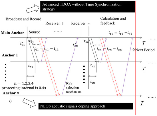
Figure 1.
Dual-receiving signal processing diagram.
In the indoor localization system, the single receiving acoustic anchors are subject to more restrictions when deployed, including the surrounding placement and the effective orientations. If the dual-receiving anchors are used, the application scope of the indoor localization system can be expanded immediately. For each acoustic anchor, if only one horn or piezoelectric tweeter is used to construct acoustic anchors, it is difficult to ensure sufficient signal quality, which is not conducive to the NLOS acoustic signal identification process. It is more flexible for the processing flow of a dual-receiving structure. In each localization period, the system should send multiple instructions from the main anchor first, and other acoustic anchors receive them on time based on their microphones in sequence, then reply to those instructions only for chirp signals with higher RSS intensity. There is a stable mapping correspondence relationship between the piezoelectric tweeter and the transmitted chirp signal. It guarantees that each two piezoelectric tweeters are linked to the corresponding acoustic anchor. It can also be seen that the received acoustic signal is an LOS acoustic signal with a greater probability according to the multiple receiving processes and mapping transmission processes. Compared with the acoustic anchor in [20,22], the dual-receiving structure will also further avoid the generation of NLOS scenarios after the RSS selecting mechanism, especially for short-duration NLOS environments.
According to the NLOS situations coping strategies in [22], the system will abandon all of the NLOS acoustic signals and only finish all of the indoor localization processes when the system has no more than one segment of NLOS acoustic signals in each localization loop. It may lead to each localization loop becoming discontinuous in the NLOS scenario with a transitory duration, which will lessen the user experience sharply. After the selection and cutting process from [22], the NLOS identification part can be undertaken. Then, the NLOS identification results in one specific localization loop can be worked out. Before compiling the Android APP, users need to measure the indoor temperature and then calculate the indoor acoustic signal propagation velocity precisely. The main anchor and other acoustic anchors are processed by the effective composite window function in the system. At this time, the core process at each dual-receiving acoustic anchor is as shown in Figure 2 below.
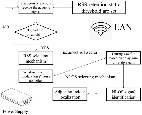
Figure 2.
Main process of RSS selection mechanism from [22] of dual-receiving acoustic anchor.
To make it interact with the indoor sensor network or cognitive IoT networks more smoothly, convenient D/A or A/D conversion modules are necessary. We made our own acoustic anchors based on the literature mentioned above; their external core parts can be seen in Figure 3 below. For each acoustic anchor, the chirp acoustic signal originally sent by the source may produce harsh noise after being processed by an external circuit, which greatly brings the user an awful experience. Therefore, the direct digital synthesis (DDS) module is required to be used in the acoustic anchor, and an analog type A amplifier will be used for the audio power amplifier to optimize the communication effect. The acoustic anchor will take STM32 as the mainstay and combine it with the feedback of the DDS module and other dual-receiving acoustic anchors. It will also complete the chirp acoustic signal and the necessary interaction process with the main anchor. In the end, the displayed results are the coordinates of this main anchor. As for the indoor localization system, the Arduino modules or LEGO components should be used for transformations (refer to [21,22]). If there are severe limitations and the NLOS scenario is not so complex, a single receiving acoustic anchor also can be used under that circumstance. We used a dual-receiving acoustic anchor based on a PCB circuit designed in [21]. The two kinds of self-made acoustic anchors are as shown in Figure 3a,b below.
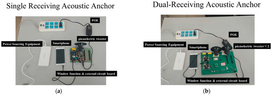
Figure 3.
Different kinds of acoustic anchors. (a) Single receiving acoustic anchor; (b) Dual-receiving acoustic anchor.
The independent receiving acoustic signal is supposed to be considered as an NLOS acoustic signal only when all of the chirp acoustic signals sent by the main anchor are blocked between the main anchor and acoustic anchors. In other words, if no less than one transmission path is not blocked or shielded, the acoustic localization signal will still be regarded as an LOS acoustic signal for each anchor. Users also can be allowed to choose to apply this mechanism in the system or not, according to their actual demands.
2.2. Decision Tree
In the key identification part of the indoor sensor system, the DT model is relatively intuitive, easy to transplant, and a widely used graphical method with a probability analysis process. In the real-world situation, its core process is to analyze the relationship between each attribute and its value according to the concept of entropy theory. In its graph structure, the analysis process is often implemented as a “tree” structure by researchers, hence the name is obtained. At the same time, it is also a supervised learning method and suitable for our research situations.
To make the indoor localization system complete the NLOS identification better, the classifier in the system is supposed to be absorbed into the difference between LOS and NLOS acoustic signals. Based on the conditions and experimental results in [11,20,21,31,32,33], it can be inferred that the LOS acoustic signal in the system will be more easily affected by the position of the acoustic anchors according to their eigenvalues. Furthermore, LOS acoustic signals will appear more frequently in the transmission path. However, due to the exceptional nature of the binary and non-linear classifier’s shortcomings, the solutions to the identification ability of NLOS signals will also bring more positive effects to the system. In this paper, the algorithm in [20] is used to complete the feature extraction process. It is clear to find out that when not normalized, the eigenvalues of each dimension between the features of the acoustic signals are greatly different. The overall dimensions of the acoustic signal feature set are not too high, and the correlation between the features is strong enough. Combining multiple factors and situations, the fitness function can be constructed based on the maximum entropy principle and the DT model.
For the entropy-increasing and independent process in this system, the fitness function value can be regarded as the numerical reference for feature set recombination, adaptive optimization, re-adjustment process, and the basis for the DT model. In our system, information entropy can be used to express the chaos degree, that is, the uncertainty of the system itself caused by the acoustic signal communication process or the cognitive IoT networks. The weighted calculation set can be considered as the mathematical expectation calculation of it. This paper combines the maximum entropy principle with the DT model to build the fitness function. For an indoor localization system, if the probability of the NLOS acoustic signal in the sample set is and there are samples in total, the information entropy can be written as follows:
Meanwhile, according to the LOS signal set and (1), we can obtain:
conditions should be considered. We can also obtain the conditional entropy of the NLOS acoustic signal, which can be written as:
Then, the information gain can be obtained. The system should finish the classification tasks with assignable differences on information gain. It can be written as:
The DT model constructed based on the principle of information gain rules is chosen, which can guarantee that the model is not too complex, and is also conducive to using the CTGSA method proposed in this paper to optimize the system. In order to avoid unnecessary misunderstanding, the fitness function can be written as:
For the classifier whose feature differentiation is not obvious enough, it is necessary to use an effective optimization algorithm to upgrade the performance of the original classifier. AFSA can be a reasonable choice. However, the traditional AFSA optimization process and DT model are apt to fall into the local minimum region [34], which will greatly affect the effectiveness. They may also become overfitted during the period. So, it is necessary to improve the traditional AFSA so that it can jump out of the local minimum area in time and cooperate with the classifier to improve the NLOS acoustic signal identification ability. It helps the system promote its positioning accuracy in complex and flexible NLOS situations. On the one hand, we decided to strengthen its ability to find the best parameters by improving the gravity search algorithm (GSA). On the other hand, the traditional AFSA may still have unreasonable parameter settings when adjusting the core parameters or the algorithm execution process, so we introduced the adaptive chaos transformation to optimize the initialization process and used the physical attenuation factor to promote convergence progress. The multiple positive factors and strategies mentioned above will tremendously improve the identification ability of the NLOS acoustic signal in the system, which is the backbone of this system. As for the peripheral part, to better combine with the dual-receiving acoustic anchor structure in [21], several 5.5 mm × 2.1 mm USB adapters should be chosen. To further reduce the possibility of NLOS scenarios, a special device can be used to fix the device under the ceiling or on the wall specifically if necessary. They are shown in Figure 4a,b below.
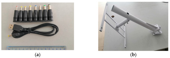
Figure 4.
Some key devices. (a) USB adapters; (b) special devices for fixing acoustic anchors.
In conclusion, the implementation of the fitness function constructed by the maximum entropy principle corresponds with the demands of the GSA optimization method or ID3 DT model more easily. The necessary peripheral equipment and reasonable deployment scheme will also be more conducive to avoiding the NLOS scenario emergence, allowing it to connect with the NLOS identification part. The system or the cognitive IoT networks are supposed to complete feature extraction based on the feature extraction algorithm in [20,21,22] first. After the audio file is cut, the system introduces adaptive chaotic transformation, adaptive gravitational search algorithm, and improved energy attenuation factor to energize the original AFSA. They form an innovative CTGSA-AFSA to optimize the DT model and improve NLOS acoustic signal recognition ability. The dual-receiving structure at each acoustic anchor and the adaptive process of cutting audio files at the main anchor need to be reconstructed according to received signal strength (RSS). After the judgment of this round, the system will only retain the acoustic localization signal with a larger RSS value, then modify the key process in the NLOS scenarios according to the selection process and finally complete indoor localization.
3. Advanced AFSA Optimization Method
If the original DT model is used directly to complete the NLOS acoustic signal identification in the system, the effect is not comparable in flexible NLOS scenarios. Especially in NLOS scenarios where the duration is unpredictable but often short, it is more obvious to verify our opinions. At the same time, this section takes the original AFSA as the principal line, using the adaptive chaos transformation, adaptive GSA [35], and the strategies for adjusting the physical attenuation factor dynamically. So, we can further strengthen the performance of the original AFSA and assemble a novel CTGSA-AFSA to help update DT in the system. Then, the NLOS acoustic signal identification ability can be improved, so as to boost the positioning accuracy under this circumstance.
3.1. Adaptive Chaotic Transformation
AFSA is a very flexible and nimble swarm intelligence optimization method that has the advantages of powerful robustness and puissant global search ability [34,36,37]. However, the original AFSA may also converge too fast in the early stage during the optimization process in the indoor localization system composed of dual-receiving acoustic anchors, which makes it impossible to fully comprehend the acoustic signal sample set in the complex and flexible NLOS scenarios. At the same time, if the convergence speed of the algorithm is too slow in the later period, it may cause shortcomings in real-world situations. Therefore, a fresh upgrading strategy is required to address the weaknesses of AFSA.
In the traditional AFSA, the research object is the biological individuals valued by the fitness function. It will indirectly feedback on the number of trials required by an individual to complete an effective task. The optimization strategy proposed in this paper will focus on the four significant processes in the algorithm: initialization, AFSA_preying, AFSA_swarming, and AFSA_following, so as to improve the effectiveness of the advanced AFSA. The following steps will focus more on the optimization strategy of adaptive chaos transformation, adaptive GSA method, and physical attenuation factor to upgrade the classification performance of the DT model.
For the initialization process of the original AFSA, it is necessary to amend parameters that control the initialization process or properties within a predictable and feasible domain. However, the strict requirements do not necessarily conform to all of the situations on LOS and NLOS acoustic signal characteristics in indoor localization systems. At the same time, the overall distribution of the training and test data sets constructed in the offline state does not always cope with the demands of the systems. Additionally, the fitness values of the two kinds of acoustic signals are not conducive to the global convergence of the algorithm when the distribution is uneven. Hence, we considered embedding the adaptive chaos transformation method to optimize the initialization strategy. According to the characteristics of the chaotic system and chaotic transformation [38], the randomness of samples and the algorithm traversal process are strengthened, so that the initialized artificial fish individuals are allocated, and the overall distribution is more consistent with the system optimization process. At the same time, this strategy will be conducive to the algorithm’s global convergence speed. The typical formula of chaotic transformation can be written as:
In the aforementioned formula, is used as the control parameter to ensure that as the initialization process goes on, the influence of chaos transformation will not be too inappreciable, thus losing the discrimination. In this paper, is taken as a fixed value. represents the fish individuals in the -th optimization loop. Its overall value will gradually become uniformly distributed. Algorithm 1 below will reveal the main process of this adaptive initialization method, and it will also bring more explanations to the entire Chaotic Transformation process. According to the requirements of the advanced AFSA initialization, the original Equation (6) needs to be modified and incorporated into the initialization process. If the lines between “/*……*/” mean the code comment part (the color green is used to write them down), the whole pseudocode can be written as:
| Algorithm 1 Adaptive initialization method based on Chaotic Transformation. |
|
3.2. Adaptive GSA
After optimizing the adaptive initialization process according to Algorithm 1, it will be more conducive to advancing the adaptive GSA part integrally. Algorithm 1 and the fitness function will establish a link between the previous process and subsequent adaptive adjustment stages in AFSA. In order to apply the fitness function value more reasonably to the optimization process of AFSA, normalization is necessary. According to Equation (5) in this paper, if the total number of samples used by the indoor localization system is recorded as , the weight of the -th sample is recorded as . Therefore, the proportion of NLOS acoustic signal samples for training in the system can be improved according to the statistical data of NLOS situations. The training weight used in the system can be obtained by , and can be acquired:
The ultimate purpose of the AFSA optimization method is classical, and the core idea is clear. In nature, some biologists believe that fish in the natural environment will tend to gather or forage in the area where the nutrition is highly concentrated and the crowding is relatively low. Thus, many researchers construct the AFSA model or methods. For the conventional AFSA optimization method, any infantry mainly completes sample reorganization, reselection, and optimization through the three stages of AFSA_preying, AFSA_swarming, and AFSA_following in the backbone of optimization. Furthermore, AFSA_preying refers to the movement in unit time taken by an artificial fish when it searches for the next position where the nutrition is higher than the current state within the fields of visual range. If is used to indicate the current state of the fish, is used to indicate another state within the field of vision, and is used to indicate the visual range. It is regarded as a variable function, which is allowed to fluctuate randomly within the effective zones. It also means that the visual range can be changed promptly in a unit of time under this state. represents a random number, so the basic description of the states can be written as follows:
If an infantry decides to move from to after finishing the comparison based on fitness function values at time , it is necessary to further update the moving range and the fields of vision or dynamical adjusting factors adaptively. If represents a random number within , the AFSA_preying behavior can be written by combining formula (8):
Although the AFSA_following behavior and the AFSA_swarming behavior have some similarities in the core process or settings, the influential factors of the two behaviors mentioned above are distinct. The action of an infantry is affected by the location where the target concentration value is the highest within the fields. The geometric center of this set can be influenced by specific partners within the fields. The concentration value of nutrients will be updated in real-time during their training processes. Judging by the Euclidean distance between the samples in the learning period, if the location of the center to be determined is better than the current location of the center, and the surrounding area is not overcrowded, the infantry will move towards the suspected center in a unit time, otherwise it performs the AFSA_preying behavior in Equation (9). Some critical threshold needs to be set by ourselves, which is related to the population density within the effective range. If takes 100 and , the AFSA_swarming behavior can be described as:
Meanwhile, the AFSA_following behavior can be described as:
Based on these equations, our updating strategies contain two main aspects. On the one hand, the weight of LOS and NLOS acoustic indoor localization signal samples can be re-adjusted due to different requirements. More flexible NLOS scenarios should be considered. Those NLOS scenarios generated by different shielding ways have a significant impact on the system in terms of time delay gain calculation, feature extraction, and system deployment [21,22]. NLOS scenarios can also be further subdivided. In our deployment process, the system is supposed to adaptively make necessary adjustments based on the statistics of various NLOS scenarios in a flexible transmission path. In order to display this part more clearly and intuitively, the displaying part of acoustic localization signal eigenvalues can be added, which is more conducive to determining the NLOS acoustic signal sample set production process and providing extensive guidance. Section 4 will describe these flexible NLOS situations, and all of the NLOS identification experiments are supposed to be finished in these man-made situations.
On the other hand, the conventional GSA is a heuristic algorithm for optimization issues. Its ultimate goal is to find the best solution for parameter seeking or the best searching process as soon as possible here [35]. This algorithm focuses on the universal law of gravity and Newton’s law of motion as the core idea. The law states:
- (1)
- The acceleration of an object is proportional to the force it receives, and inversely proportional to its mass.
- (2)
- The mutual gravitation between particles is proportional to the product of their masses and inversely proportional to the square of their distances in the universe.
- (3)
- Each particle uses force to attract other particles, and there are forces and reactions continuously.
The adaptive GSA will be involved in the process of AFSA_prey, AFSA_swarm, and AFSA_follow in the system, and the energy attenuation factor will be introduced to control the individual’s movement distance as the algorithm proceeds. Thus, the convergence speed is not expected to be too slow, and the real-time requirements of the system are supposed to be elevated.
For the indoor localization system in this paper, the acoustic signal is taken as the research object to complete the promotion or optimization based on these three criteria. In conventional AFSA, the samples lack the cognitive ability of individual perception, global integrity, and global sensitivity adjustment. These weaknesses will directly affect the convergence speed and the identification effect of the NLOS acoustic localization signal. It will be reflected and can evaluate the index of reselecting, rearrangement, and training process, which may affect the positioning accuracy in NLOS scenarios. Therefore, it intends to use GSA to intervene in the behavior of AFSA_prey, AFSA_swarm, and AFSA_follow. For the GSA improved by chaotic transformation, the acoustic localization signal samples are evaluated by the fitness function in Equation (5). As for the moment , represents the fitness function value with the best sample value in the fields of vision. represents the fitness function value with the worst sample value in the fields of vision, and the mass of individual samples can be expressed by the following formula:
is the initialized universal gravitation coefficient [35], and is fixed here. is set as a constant number, then the acceleration factor of AFSA_prey, AFSA_swarm, and AFSA_follow can be calculated as:
As for the whole CTGSA process, both the CT part and the GSA part are of great importance. The identification part of this system is supposed to be optimized according to the real-world situation. There are two basic rules or targets: one is accuracy, and the other is running time. When designing the optimization method for AFSA, the two points mentioned above need to be considered. Therefore, CTGSA is the integration plan after combining these two parts. Among them, the CT part greatly improves the initialization effect of the classifier when the number of samples is limited. It will enable more samples to participate in the formation of weights and preliminary grouping results in the initialization process, not only for those high-grade samples but also for those normal samples. In the process of training, aiming at the weakness of AFSA itself, introducing GSA into the main process of AFSA will make the training process faster and more efficient. Basically, according to Equations (9) and (13), the AFSA_ preying behavior in traditional AFSA is modified. For individual actions in unit time, the original process should be adjusted as follows:
In order to control the convergence speed and increase the practicability, the physical strength transformation model is introduced to illustrate the external force attenuation factor for the AFSA_swarming and the AFSA_following behavior. The physical strength transformation model is designed and implemented according to the regulation based on animals’ exercise intensity and the limited upper bound of physical strength in nature. On the one hand, the physical consumption number directly affects the AFSA_swarming behavior and the AFSA_following behavior of the fish itself. At the same time, to make the algorithm converge faster, the most suitable parameter is expected to be used as soon as possible. On the other hand, the AFSA_preying behavior is regarded as a physical energy maintenance service, so this parameter is not added in the process during updating. For Equations (10) and (11), the new generating field indicates the maximum range of the movement at this stage. Therefore, as for , if the upper limit of physical strength is set to 100, the lower limit of physical strength should be set to 20 during the training process. The algorithm needs to retain a buffering interval or protection interval until the physical strength number is completely stabilized. A linear transformation model is introduced here. For generation -th individuals, the corresponding physical strength value is , then we have:
Obviously, the physical strength number of each individual in one cluster may not decrease at the same time. The main flow of the AFSA algorithm optimized by multiple strategies in this paper is as follows in Figure 5:
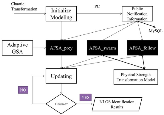
Figure 5.
CTGSA main optimization method.
3.3. Summary
In the indoor localization systems, if the upgrading strategies mentioned above are added, it will effectively improve the NLOS identification effect. Then, it tells the user whether the location is appropriate through more accurate positioning results. In detail, the re-selection and re-organization process on these branch samples for the existing results will be completed, thus adjusting the main process precisely based on CTGSA-AFSA, at the same time retaining the probability of elaborating the established learning direction or tendency in the system. In addition, they will directly guarantee that acoustic signal samples can obtain more reasonable training weights under different NLOS scenarios. It will make the overall NLOS coping mechanism more comprehensive. This can also be reflected in the randomness of the sample movement process. Meanwhile, the methods will make sure that the physical strength transformation model value seldom changes to zero. According to different scenarios in the system, the flexible samples will further improve the performance of CTGSA-AFSA.
As for other AFSA optimization methods, although many of them may have achieved considerable results, it does not mean that they can be directly used in the core part of this system and complete the identification of NLOS acoustic signals in the dual-receiver structure anchors in our flexible NLOS situations. In fact, these updating strategies on AFSA need to balance two factors: one is the accuracy, and the other is how much time it takes to complete the training. In some scenarios, the acoustic signal data set in an offline state can be adopted to complete the necessary training and then be used in multiple scenarios. However, this does not mean that the results of offline data set training for static NLOS acoustic localization signals must be applied to complex and flexible NLOS scenarios. Accordingly, excellent schemes from the recent literature [39,40,41] are used for comparison. The data set used is from the literature [22] in this part. During its acoustic signal data-building process, those static NLOS scenarios in different situations are produced. In order to facilitate comparison, on the premise of using the same data set, the upgrade methods are used to upgrade SVM to compare the effects of AFSA optimization methods. For a more rigorous comparison, 20 independent experiments are conducted for each group, then the overall results are counted and the average value of each experiment result is calculated. Our method is compared with the methods mentioned above for upgrading the SVM, evaluate the effect, and the specific results are showed in Table 1:

Table 1.
Comparison of some AFSA-SVM optimization method effects.
Among these methods, the identification accuracy of some methods obtained may be better than the methods used in this paper, but their training times were much longer than those of the methods used in this paper. In the static NLOS scenario [20,22], the accuracy should be paid more attention than the training time. However, in the dynamic NLOS scenarios, the RSS selecting mechanism processed from [22] may be used too frequently due to their long training time, which may lead to uncontrollable and serious consequences. Therefore, researchers must better balance the relationship between accuracy and training time in flexible NLOS situations. In the system involved in this paper, it is also likely to coordinate the final effect in the real-world situation due to the mechanism or solutions from [22]. When designing and deploying the indoor localization system, it is necessary and wise to achieve the necessary balance according to the actual situation of this site when selecting the AFSA optimization scheme in indoor sensor systems. CTGSA time is not included in the above statistical results. This is because this process mainly affects the initialization stage, which can be used in an offline state, and is also one of the advantages of our method.
In the next Section, our man-made and flexible NLOS situations will be used to evaluate the CTGSA-AFSA-DT methods. These effective changes make NLOS identification more promising, and the enhanced DT classification model can better adapt to the multiple receiving acoustic anchors. At the same time, to make the NLOS identification part of the system better interact with the multiple platforms, developers are bound to specify the way to implement the proper cross-platform interaction before the deployment of the system. Some mobile terminals can be applied through special IP protocols or other adaptive interactive ways, and can also be transferred through cloud service technology if necessary. For example, using Unity Hub 3.3.0-c8 can be a good choice for Kinect sensor system. It supports not only the development of Android APPs, but also other projects. However, for some IoT devices, such as Kinect, Leap Motion, Halcon Camera, etc., the official software development kit (SDK) does not always contain all the mainstream computer programming languages, so the development plan should be determined according to the whole implementation project.
4. System Analysis and Experiment
4.1. System Setup and Dual-Receiving Method
When constructing the acoustic signal data set, it is essential to consider various shielding ways that actually happen in the scenarios. At the same time, no more than one random transmission path is supposed to be blocked in a single localization loop. Meanwhile, only when two pieces of chirp acoustic signals received by each acoustic anchor are both blocked, they are regarded as NLOS acoustic signals at that moment. The green dot lines in Figure 6 below besiege the indoor localization area. Meanwhile, it is supposed to consider the dynamic NLOS situations. So, we finish the patrol route for the system, which is shown in Figure 6 below by red arrow. All of the pedestrians or runners moving with the routes take shape in our man-made flexible NLOS situations. With the necessary functions and strategies in [20,21,22], the overall framework of the indoor localization system is as follows.
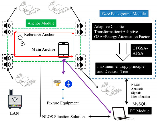
Figure 6.
System architecture diagram and man-made routes for flexible NLOS situations.
Although the COVID issue and some other negative factors brought us some troubles, we still gathered nine people as our NLOS man-made dynamic and flexible scenario production volunteers. Eight of them were male and one was female. They all had enough comprehension ability to complete the instructions as required. They were not influenced by diseases that could affect normal human actions during the experiment. At the same time, we also took into account the negative impact of the volunteers’ physical energy decline as the experiment proceeded, so that each volunteer could not experiment for more than an hour. Specifically, volunteers followed the designed route (red arrow in Figure 6) in the indoor localization periods, thus finishing building NLOS man-made dynamic and flexible scenarios. The man-made scenarios were divided into four patterns: slow speed, normal speed, running speed (or sliding forward), and random mode. Among them, the slow speed was far lower than the normal speed. According to our measurements, the slow speed was around 0.5~0.6 m/s. The normal walking speed was about 1.2~2 m/s. The running speed or sliding forward was about 4~7 m/s. It was difficult for the volunteers to achieve full speed forward like in outside environments due to the limitations of the indoor area. As for the last mode, the system selected a random number from 1, 2, and 3 first, and then determined the action pattern under this mode according to the number obtained equiprobably.
To finish the dual-receiving process, PCB boards were required. Referring to [21], the PCB circuit board contained an electrodeless capacitor, TDA2030A audio power amplifier, DDS module, TPS5430 adjustable voltage module, and MP1584EN buck converter. The piezoelectric tweeter in each acoustic anchor of the dual-receiving structure could be fixed with specific devices or powerful glue without a disgusting smell. The signal acquisition module on the PCB board needed to handle the acquired acoustic signal, so as to ensure that the protection interval of the indoor localization system in a single localization loop was long enough to complete all processing procedures. The acoustic signal delay gain or the generation time processed by the RSS selecting mechanism in the classification module turned out to be essential under this circumstance. Then, it was expected to complete the wav file cutting at the main anchor. This part could be determined based on delay gain or relative gain according to the implementation schemes of the system [11,22]. After that, the 9-dimensional feature extraction was completed on Android, and then the classification was completed through PC. The results were returned to the main anchor in time, which were s processed by the NLOS acoustic signal identification part based on the CTGSA-AFSA-DT model before. Finally, the system finished the indoor localization if necessary, so it benefit the indoor sensor systems or the cognitive IoT networks for orientation issues.
Before the main process, the main anchor must recognize the beginning time of the initial localization loop. During these periods, all of the necessary permissions or accesses are required by the applications in the system. As for the advanced TDOA process, its core process is to implement the generalized cross-correlation (GCC) method and NLOS identification. Cross-platform interactive processing should also be added. The data are transferred into the PC module or the local server, and then can be displayed with the data visualization services through Tableau Software 10.4, HTML, or other ways. There are also many considerable ways to build up the LAN module, which will provide a reliable Wi-Fi environment for the system. The PC needs to make sure that there is no port number conflict before it begins to work. At this time, all mobile devices in the system need to be connected. As shown in Figure 6 above, the anchor module transmits data and interacts with the background module through the LAN module, and also interacts with the classification module when necessary, referring to the framework plans designed in [11,22]. Judging by the reference anchor, the system does not need to implement strict clock synchronization and only needs to carry out skillful mathematical operation in [11]. Once the localization loop starts, each acoustic anchor can obtain the real-time position of the main anchor in the form of a constant coordinate value in our system.
For the dual-receiving process, the main anchor will be used in batches during the instruction sending phase, and the following process requires sending at a fixed interval of 0.4 s. The protection interval also avoids the potential risks caused by reverberation. Each acoustic anchor receives the instructions broadcasted from the main anchor in a counterclockwise loop according to the order arranged in Figure 6. When the previous acoustic anchor does not comply with the RSS selection mechanism, the next acoustic anchor will temporarily be in a silent state. After the break, the system is supposed to continue the next loop. The main anchor is expected to receive the returning instructions and calculate the coordinates within sufficient protection intervals in addition to completing the signal broadcasting process. In order to better adapt to the dual-receiving acoustic anchor function, it is also necessary to add the recording function to ensure that the GCC-PHAT method can be completed to obtain the necessary chirp signal transmission delay difference for the system. It can also help the system to calculate the main anchor’s coordinates in time. The following step will make the indoor localization system abandon no more than one NLOS acoustic signal according to the NLOS identification results and the NLOS situations coping mechanism from [22]. On the one hand, it should be emphasized that using RSS intensity alone is not reliable enough to fully identify NLOS acoustic signals. On the other hand, it is quite convincing that the total transmission path must contain at least three LOS acoustic signals after the RSS selection mechanism is adopted. Otherwise, the main process will not be promoted. In detail, as for dual-receiving acoustic anchors, there will be the following three issues according to the RSS selection mechanism on each acoustic anchor:
- If both chirp signals’ RSS values exceed the retention threshold, then only the time corresponding to the first chirp acoustic signal and the received signal shall be taken as the standard.
- If only one of them has enough RSS intensity that exceeds the retention threshold, then only the time corresponding to the stronger one and the received signal shall be taken as the standard.
- If both RSS values fail to exceed the retention threshold, the “invalid reception” command is supposed to return to the main anchor, and then the system terminates this localization loop in advance.
Therefore, the execution process of the main anchor can be shown in Figure 7 below:
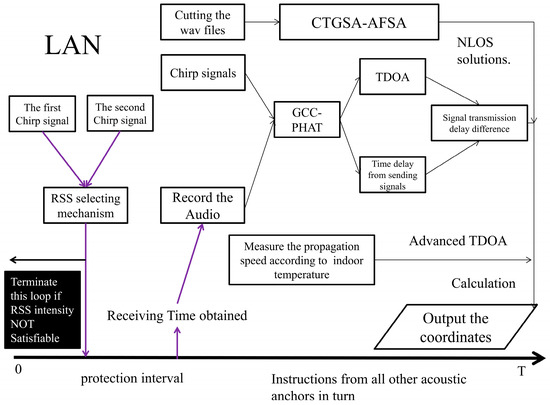
Figure 7.
Main anchor working time axis in one localization loop. The NLOS solutions are adopted from [22].
In order to cooperate with the feature extraction algorithm implemented in Android smartphones, the system may need to consider the Chan algorithm [42] or Taylor [43] algorithm to assist in the NLOS identification process after the audio segmentation is finished. When the system contains four different effective acoustic signal transmission paths, these two algorithms can also be used to calculate the appearance probability on NLOS acoustic signal. The maximum likelihood estimation is expected to be used according to prior information by statistics and necessary mathematical operations to assist the system in completing necessary judgments. Finally, the system will give the final result by displaying the coordinates on the Android APP appropriately.
To guarantee that, even after the compulsory processing in the system, the next loop will still not be affected, the time interval required for the necessary system termination is set as 5 s. If NLOS scenarios happen too frequently in the system, the normal function may be affected passively. However, on the one hand, to make the final results in complex and flexible NLOS scenarios more accurate, we still consider them as a necessary sacrifice, although the protection intervals reduce the efficiency of system utilization. On the other hand, the deployment scheme also needs to be adjusted according to the indoor sites, which will further reduce the possibility of NLOS scenarios. The CTGSA-AFSA method is used to optimize DT for NLOS acoustic signal identification method, and the subsequent NLOS situation coping mechanism is adopted when necessary. Meanwhile, the working conditions and the Android APP permissions needed should also be considered cautiously. In total, the system working time axis in an indoor localization loop is as follows in Figure 8.
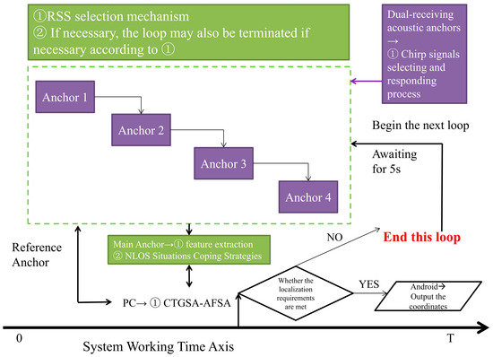
Figure 8.
Indoor localization system working time axis in one localization loop.
4.2. Experiment and Analysis
All of the experimental situations can be divided into two parts: the LOS scenario and the NLOS scenario. As for the NLOS scenario, we were aiming at a variety of NLOS scenarios, including the static scenario and the dynamic scenario. For static NLOS situations, the transmission path was blocked by a rigid body object (plastic box, paper box, wardrobe, etc.) whose size was not large enough to occlude multiple acoustic anchors at the same time. As for the first batch, the total number of static NLOS acoustic signals was 2000 in this situation. In contrast, 2000 LOS acoustic signals were used. It was vital to consider the possibility of the NLOS scenarios with a short duration; these samples were randomly placed in the set. So, different from the samples in [20,22], the new data set was used to complete the experiment. As for the second batch, 3600 NLOS dynamic acoustic signals were included. The computer used was a Lenovo R480 from Lenovo Inc., Beijing City, China.
For dynamic NLOS situations, these communication paths were blocked by our volunteers with four different patterns. We believe that these man-made and flexible NLOS situations turned out to be useful. For these dynamic situations, all of the volunteers helped us obtain 3600 dynamic NLOS signals. Single receiving structure and dual-receiving structure were also compared with each classification algorithm. Compared with the static NLOS situations, the results are showed in Table 2 (italic font indicates the method used in this paper):
Table 2.
Accuracy comparisons of each method under static NLOS situations.
As for the dynamic NLOS situations, the accuracy results derived from four different patterns were averaged and added to facilitate the function. The results are showed in Table 3:
Table 3.
Accuracy comparisons of each method under dynamic NLOS situations.
So, it is clear that the dual-receiving structure gave the system better performance in NLOS situations. Additionally, it was vital to compare the NLOS acoustic signal identification methods in every four patterns towards the dynamic NLOS situations. For the sake of convenience, the methods mentioned above were divided into single receiving and dual-receiving parts, and the numbers {1}~{16} were used in turn. As for the single receiving part, all of the methods’ accuracies were as follows, in detail:
The following conclusions were drawn based on the Figure 9:
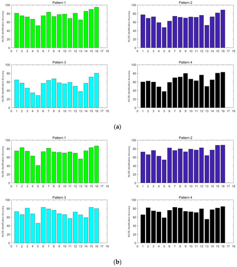
Figure 9.
NLOS identification accuracy based on different methods. (a) Single receiving accuracy comparisons of four dynamic NLOS patterns.; (b) dual-receiving accuracy comparisons of four dynamic NLOS patterns.
- (1)
- In the complex and flexible NLOS scenarios, the dual-receiving acoustic anchors and the adaptive acoustic signal receiving and transmitting processes improved the NLOS acoustic signal classification performance in the system significantly. Among them, the dual-receiving structure in Pattern 1 and Pattern 2 yielded no significant improvement compared with the original version, while the dual-receiving structure in Pattern 3 (running state) yielded a 15% increase in NLOS acoustic signal identification accuracy compared with the original version. Pattern 4 also showed an increase of 4~13%. It truly brings some equipment complexity, but it is considered worthwhile.
- (2)
- Compared with the identification accuracy in the static scenario, the dynamic NLOS scenarios had many differences among all methods mentioned above. Among them, since the action rules of Pattern 1 and Pattern 2 may have coincided with the NLOS coping mechanism in the system for some reason, the results of Pattern 1 and Pattern 2 were similar to those in the static NLOS scenario. However, as for Pattern 3 and Pattern 4, the results were significantly different from those in the static NLOS scenarios due to factors such as the coincidence degree of random mechanisms and rules of actions. Therefore, the system needs to select an appropriate way to produce its training data set according to the situations in the NLOS scenario during deployment, which will enable the system to play a better role. Indoor sensor networks or cognitive IoT networks are ready to obtain the users’ locations, and then they will provide the users with better locations. Finally, the networks will benefit if the users are willing to obey the notifications from this system.
In our experiment, different models of smartphones (e.g., XiaoMi 10 from XiaoMi Inc., Wuhan City, China. Huawei Honor 3, 4, 5, etc. from Huawei Inc. Shenzhen City, China) were adopted as the core parts of the main anchor. After determining the fixed coordinates to calculate the error accuracy, it was necessary to define the positive direction of the X axis, the positive direction of the Y axis, and the position of the O point in this site. The NTS-334R electronic total station could be used to complete the calibration. During the measurements, all 12 fixed coordinates were considered to calibrate the position. These coordinates to be measured were (1, 1), (1, 1.5), (1, 2), (1, 2.5), (1.5, 2.5), (2, 2.5), (2.5, 2.5), (2.5, 2), (2.5, 1.5), (2.5, 1), (2, 1) and (1.5,1) respectively. The four dual-receiving acoustic anchors were respectively placed at (0, 0), (0, 4), (4, 4), and (4, 0). Enough distance was required to avoid reverberations or other negative interactions among the acoustic anchors, which needed to be reconsidered before deployment. The reference anchor was fixed at (1.5, 1.5), with a height of 1.5 m from the ground. The APP at the main anchor controlled the whole localization period. The NLOS identification algorithm proposed in this paper was implemented on a PC platform, which carried out vital information transfer and instruction storage commands. The NLOS acoustic signal coping mechanism in [22] was introduced to complete the process of all indoor localization systems. Some periods may have also contained dynamic NLOS situations. Meanwhile, to expand the application scope of the reference anchors effectively, we chose a VT-888 retractable stainless-steel bracket (video flexible tripod), which was often used for supporting KinectV2 in the past. We used it for supporting the reference anchor, as shown in Figure 10a below. For each coordinate, experiments were conducted 20 times. If the system was supposed to finish the process, we recorded the results and calculated the average values of the coordinates. The single receiving experiment situation is shown in Figure 10b below, and the dual-receiving experiment situation is shown in Figure 10c:
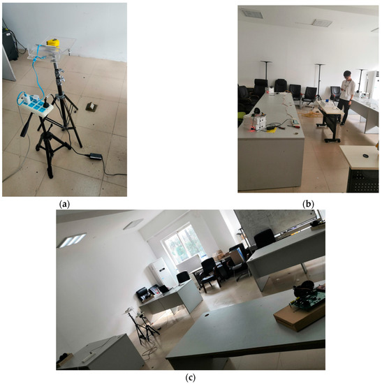
Figure 10.
Experiment situations. (a) The reference anchor; (b) single receiving experiment situation; (c) Dual-receiving experiment situation.
Among the 12 coordinates to be measured, only (1, 1.5), (2.5, 2), and (2.5, 1.5) had larger positioning errors, which were 0.1579 m, 0.1882 m, and 0.1758 m, respectively. The errors of other coordinates were all less than 0.15 m. There were few differences among these coordinates. At the same time, some accidental factors may also need to be considered, such as indoor temperature, the unstable effect of piezoelectric tweeters, etc. It was quite certain that selecting a higher-quality omnidirectional facility as an essential part of the acoustic anchor would greatly reduce the contingency and uncertainty of our experiments. Once more experiments were repeated, the overall results might be different, and the error distribution would gradually tend to normal distribution in total.
After the system completed CTGSA-AFSA optimization and applied the NLOS acoustic signal coping mechanism, it could be seen that the novel method proposed in this paper achieved excellent results with the help of a four-pattern data set and dual-receiving structures. The data set that contained the four patterns of NLOS situations was proved to have a positive impact on the NLOS identification ability in complex and flexible situations compared with the single receiving method. These precise positioning results will help indoor sensor networks or cognitive IoT networks adjust the user’s location and play a better role. In detail, they are shown in Table 4 as follows:
Table 4.
Positioning error of each coordinate.
5. Conclusions
For the requirement to notify users of their locations in indoor sensor networks or cognitive IoT networks, we decided to add an adaptive indoor localization system to deal with such a phenomenon. Accordingly, this paper proposed a novel NLOS acoustic signal identification method and an adaptive dual-receiving acoustic signal processing method for indoor localization systems. With these, we were able to obtain better indoor localization results in complex and flexible NLOS situations.
Our key works are as follows: (1) The acoustic anchor of the dual-receiving structure was added in complex and flexible NLOS scenarios. First of all, an RSS selection mechanism and an improved TDOA algorithm were adopted to accomplish the entire indoor localization without the clock synchronization part. This structure greatly improved the acoustic signal transmission effect in complex and flexible NLOS scenarios. (2) As for the conventional NLOS acoustic signal identification part of DT, an advanced method, namely CTGSA-AFSA, was introduced to upgrade the classifier. It contains an adaptive chaos transformation strategy, improved GSA optimization method, and adaptive physical attenuation model for the initialization process, which enhances the classifier’s ability to identify NLOS acoustic signals in complex and flexible scenarios in total. In our experiments, our novel AFSA optimization method could obtain a better effect and took less time compared with the original version. There is no doubt that our method can balance the relationship between accuracy and running time in flexible NLOS situations. Then, different classifiers or methods were used for comparison in man-made flexible NLOS scenarios. Finally, the artful use of dual-receiving structural acoustic anchors enabled improvements in NLOS identification accuracy. For the 12 fixed coordinates, the results show that after optimizing with the novel method proposed in this paper, the minimum positioning error was 5.31 cm, and the maximum positioning error was only 18.82 cm in this system. The data set that contained four patterns of NLOS situations benefited the localization process substantially.
The proposed NLOS acoustic signal identification method also has some limitations. In addition, if users want to more comprehensively and skillfully integrate functions into a system, it is considered better to deal with cross-platform issues in case the system may not be able to meet performance expectations according to sensor coefficients. If necessary, some hardware and peripherals [2,3,4,44] should be introduced. In fact, these mobile devices will also have a negligible impact on the system. Meanwhile, cognitive computing theory and intelligent sensor networks will also improve the efficiency and accelerate the automation or intelligence of these indoor sensor systems.
In future works, for more complex and flexible scenarios, more and more machine learning researchers will try to use ensemble learning methods to optimize or create new algorithms or networks, including strong classifiers constructed by the bagging method [44,45] or new functions or models constructed by the boosting method [46,47]. Their superior performance will not only be reflected in a classification module, but also in regression analysis issues. This will also become a key motivation for acoustic signal identification research in the next stage.
Author Contributions
Conceptualization, R.K. and M.W.; software, R.K. and X.L. (Xin Liu); experiment analysis, R.K. and X.L. (Xiaojuan Liu); writing—review and editing, R.K., M.W. and H.Q.; funding acquisition, M.W. and H.Q. All authors have read and agreed to the published version of the manuscript.
Funding
This research work is supported by the National Natural Science Foundation of China under Grants 62071135 and 61961010. It is also supported by Innovation Project of GUET Graduate Education No. 2023YCXB05.
Institutional Review Board Statement
Not applicable.
Informed Consent Statement
Not applicable.
Data Availability Statement
All of the grants for this manuscript are still in the research phase, and some research data or key codes are currently limited to disclosure within the project team. However, some wav files of the acoustic localization signals involved in this system can be provided. If necessary, you can contact Ruixiang Kan via email (bbklasnic@glut.edu.cn) to obtain the Baidu Netdisk (Baidu Cloud) URL link and then download the files you need. Once the link is gone, you can contact the authors of this article to obtain the latest link.
Acknowledgments
We are very grateful to volunteers from GUET and GLUT for their assistance in the experimental part of this manuscript. Meanwhile, Yanbing Liu’s Electronic Total Station Using Tutorial Lesson is also appreciated.
Conflicts of Interest
The authors declare that there are no interests or personal relationships that could have appeared to influence the work reported in this paper.
References
- Chen, B.; Lan, S. Research on Museum Educational Display Based on Image Recognition Tracking. Wirel. Commun. Mob. Comput. 2022, 2022, 7314887. [Google Scholar] [CrossRef]
- Wang, H.; Shi, J.; Luo, X. Swimmer’s Posture Recognition and Correction Method Based on Embedded Depth Image Skeleton Tracking. Wirel. Commun. Mob. Comput. 2022, 2022, 8775352. [Google Scholar] [CrossRef]
- Gao, F.; Fang, W.; Sun, X.; Wu, Z.; Zhao, G.; Li, G.; Li, R.; Fu, L.; Zhang, Q. A novel apple fruit detection and counting methodology based on deep learning and trunk tracking in modern orchard. Comput. Electron. Agric. 2022, 197, 107000. [Google Scholar] [CrossRef]
- Mansoor, M.; Amin, R.; Mustafa, Z.; Sengan, S.; Aldabbas, H.; Alharbi, M.T. A machine learning approach for non-invasive fall detection using Kinect. Multimed. Tools Appl. 2022, 81, 15491–15519. [Google Scholar] [CrossRef]
- Liu, M.; Cheng, L.; Qian, K.; Wang, J.; Wang, J.; Liu, Y. Indoor acoustic localization: A survey. Hum. Cent. Comput. Inf. Sci. 2020, 10, 2. [Google Scholar] [CrossRef]
- Guzsvinecz, T.; Szucs, V.; Sik-Lanyi, C. Suitability of the Kinect Sensor and Leap Motion Controller—A Literature Review. Sensors 2019, 19, 1072. [Google Scholar] [CrossRef]
- Cai, C.; Zheng, R.; Luo, J. Ubiquitous Acoustic Sensing on Commodity IoT Devices: A Survey. IEEE Commun. Surv. Tutor. 2022, 24, 432–454. [Google Scholar] [CrossRef]
- Li, Z.; Qin, C.; Wang, Y. WiFi/PDR integrated navigation with robustly constrained Kalman filter. Meas. Sci. Technol. 2020, 31, 084002. [Google Scholar] [CrossRef]
- Gentner, C.; Günther, D.; Kindt, P.H. Identifying the BLE Advertising Channel for Reliable Distance Estimation on Smartphones. IEEE Access 2022, 10, 9563–9575. [Google Scholar] [CrossRef]
- Yang, Y.; Wang, D.; Chen, L.D.; Zhang, Q. An Improved Indoor 3-D Ultrawideband Positioning Method by Particle Swarm Optimization Algorithm. IEEE Trans. Instrum. Meas. 2022, 71, 1–11. [Google Scholar] [CrossRef]
- Zhang, P.; Wang, M.; Qiu, H.; Kan, R. Acoustic Localization System based on Smartphone without Time Synchronization. In Proceedings of the 2020 5th International Conference on Information Science, Computer Technology and Transportation (ISCTT), Shenyang, China, 11–15 November 2020; pp. 475–481. [Google Scholar]
- Misra, P.; Jha, S.; Ostry, D. Improving the coverage range of ultrasound-based localization systems. In Proceedings of the 2011 IEEE Wireless Communications and Networking Conference, Cancun, Mexico, 28–31 March 2011; pp. 605–610. [Google Scholar]
- Mandal, A.; Lopes, C.V.; Givargis, T.; Haghighat, A.; Jurdak, R.; Baldi, P. Beep: 3D indoor positioning using audible sound. In Proceedings of the Second IEEE Consumer Communications and Networking Conference, Las Vegas, NV, USA, 6 January 2005; pp. 348–353. [Google Scholar]
- Peng, C.; Shen, G.; Zhang, Y. BeepBeep: A high-accuracy acoustic-based system for ranging and localization using COTS devices. ACM Trans. Embed. Comput. Syst. 2012, 11, 1–29. [Google Scholar] [CrossRef]
- Liu, K.; Liu, X.; Li, X. Guoguo: Enabling Fine-Grained Smartphone Localization via Acoustic Anchors. IEEE Trans. Mob. Comput. 2016, 15, 1144–1156. [Google Scholar] [CrossRef]
- Tan, C.; Zhu, X.; Su, Y.; Wang, Y.; Wu, Z.; Gu, D. A low-cost centimeter-level acoustic localization system without time synchronization. Measurement 2016, 78, 73–82. [Google Scholar] [CrossRef]
- Höflinger, F.; Zhang, R.; Hoppe, J.; Bannoura, A.; Reindl, L.M.; Wendeberg, J.; Bührer, M.; Schindelhauer, C. Acoustic Self-calibrating System for Indoor Smartphone Tracking (ASSIST). In Proceedings of the 2012 International Conference on Indoor Positioning and Indoor Navigation (IPIN), Montbéliard, France, 13–15 November 2012; pp. 1–9. [Google Scholar]
- Chen, X.; Chen, Y.; Cao, S.; Zhang, L.; Zhang, X.; Chen, X. Acoustic Indoor Localization System Integrating TDMA+FDMA Transmission Scheme and Positioning Correction Technique. Sensors 2019, 19, 2353. [Google Scholar] [CrossRef]
- Groves, P.D.; Adjrad, M. Likelihood-based GNSS positioning using LOS/NLOS predictions from 3D mapping and pseudoranges. GPS Solut. 2017, 21, 1805–1816. [Google Scholar] [CrossRef]
- Zhang, L.; Huang, D.; Wang, X.; Schindelhauer, C.; Wang, Z. Acoustic NLOS Identification Using Acoustic Channel Characteristics for Smartphone Indoor Localization. Sensors 2017, 17, 727. [Google Scholar] [CrossRef]
- Wang, M.; Duan, N.; Zhou, Z.; Zheng, F.; Li, X.; Zhang, G. Indoor PDR Positioning Assisted by Acoustic Source Localization, and Pedestrian Movement Behavior Recognition, Using a Dual-Microphone Smartphone. Wirel. Commun. Mob. Comput. 2021, 2021, 9981802. [Google Scholar] [CrossRef]
- Kan, R.; Wang, M.; Zhou, Z.; Zhang, P.; Qiu, H. Acoustic Signal NLOS Identification Method Based on Swarm Intelligence Optimization SVM for Indoor Acoustic Localization. Wirel. Commun. Mob. Comput. 2022, 2022, 5210388. [Google Scholar] [CrossRef]
- Tölgyessy, M.; Dekan, M.; Chovanec, Ľ.; Hubinský, P. Evaluation of the Azure Kinect and Its Comparison to Kinect V1 and Kinect V2. Sensors 2021, 21, 413. [Google Scholar] [CrossRef] [PubMed]
- Li, C.; Fahmy, A.; Sienz, J. An Augmented Reality Based Human-Robot Interaction Interface Using Kalman Filter Sensor Fusion. Sensors 2019, 19, 4586. [Google Scholar] [CrossRef] [PubMed]
- Gang, M.S.; Kim, H.J.; Kim, D.W. Estimation of Greenhouse Lettuce Growth Indices Based on a Two-Stage CNN Using RGB-D Images. Sensors 2022, 22, 5499. [Google Scholar] [CrossRef] [PubMed]
- Gong, L.; Wang, C. Research on Moving Target Tracking Based on FDRIG Optical Flow. Symmetry 2019, 11, 1122. [Google Scholar] [CrossRef]
- Haldorai, A.; Sivaraj, J.; Nagabushanam, M.; Roberts, M.K. Cognitive Wireless Networks Based Spectrum Sensing Strategies—A Comparative Analysis. Appl. Comput. Intell. Soft Comput. 2022, 2022, 6988847. [Google Scholar] [CrossRef]
- Wang, Y. The Application of Computer-Based Multimedia Technology in Cognitive Computing. Comput. Intell. Neurosci. 2022, 2022, 3354576. [Google Scholar] [CrossRef] [PubMed]
- Sreedevi, A.G.; Harshitha, T.N.; Sugumaran, V.; Shankar, P. Application of Cognitive Computing in Healthcare, Cybersecurity, Big Data and IoT: A Literature Review. Inf. Process. Manag. 2022, 59, 102888. [Google Scholar] [CrossRef]
- Jin, R.; Cai, C.; Deng, T.; Li, Q.; Zheng, R. MotionBeep: Enabling Fitness Game for Collocated Players with Acoustic-Enabled IoT Devices. IEEE Internet Things J. 2021, 8, 10755–10765. [Google Scholar] [CrossRef]
- Cai, C.; Ma, X.; Hu, M.; Yang, Y.; Li, Z.; Liu, J. SAP: A Novel Stationary Peers Assisted Indoor Positioning System. IEEE Access 2018, 6, 76475–76489. [Google Scholar] [CrossRef]
- Luo, J.A.; Shao, X.H.; Peng, D.L.; Zhang, X.P. A Novel Subspace Approach for Bearing-Only Target Localization. IEEE Sens. J. 2019, 19, 8174–8182. [Google Scholar] [CrossRef]
- Jia, N.; Shu, H.; Wang, X.; Xu, B.; Xi, Y.; Xue, C.; Liu, Y.; Wang, Z. Smartphone-Based Social Distance Detection Technology with Near-Ultrasonic Signal. Sensors 2022, 22, 7345. [Google Scholar] [CrossRef]
- Li, X.L. A New Kind of Intelligent Optimization Method-Artificial Fish Swarm Algorithm. Ph.D. Thesis, Zhejiang University, Hangzhou, China, 2003. [Google Scholar]
- Rashedi, E.; Nezamabadi-pour, H.; Saryazdi, S. GSA: A Gravitational Search Algorithm. Inf. Sci. 2009, 179, 2232–2248. [Google Scholar] [CrossRef]
- Li, X.; Shao, Z.; Qian, J. An optimizing method based on autonomous animats: Fish-swarm algorithm. Syst. Eng. Theory Pract. 2002, 11, 32–38. (In Chinese) [Google Scholar]
- Hu, J.; Zeng, X.; Xiao, J. Artificial Fish School Algorithm for Function Optimization. In Proceedings of the 2010 2nd International Conference on Information Engineering and Computer Science, Wuhan, China, 25–26 December 2010; pp. 1–4. [Google Scholar]
- Singh, A.K. Complex Chaotic Systems and Its Complexity. In Mathematical Analysis and Applications; Chadli, O., Das, S., Mohapatra, R.N., Swaminathan, A., Eds.; Springer Proceedings in Mathematics & Statistics; Springer: Berlin/Heidelberg, Germany, 2021; p. 381. [Google Scholar]
- Miao, J.; Li, B.; Du, X.; Wang, H. A Substation Fire Early Warning Scheme Based on Multi-Information Fusion. Electronics 2022, 11, 4222. [Google Scholar] [CrossRef]
- Ni, J.; Tang, J.; Wang, R. Hybrid Algorithm of Improved Beetle Antenna Search and Artificial Fish Swarm. Appl. Sci. 2022, 12, 13044. [Google Scholar] [CrossRef]
- Huang, X.; Xu, G.; Xiao, F. Optimization of a Novel Urban Growth Simulation Model Integrating an Artificial Fish Swarm Algorithm and Cellular Automata for a Smart City. Sustainability 2021, 13, 2338. [Google Scholar] [CrossRef]
- Chan, Y.T.; Ho, K.C. A simple and efficient estimator for hyperbolic location. IEEE Trans. Signal Process. 1994, 42, 1905–1915. [Google Scholar] [CrossRef]
- Foy, W.H. Position-Location Solutions by Taylor-Series Estimation. IEEE Trans. Aerosp. Electron. Syst. 1976, AES-12, 187–194. [Google Scholar] [CrossRef]
- Tong, F.; Zhang, Y. Spectral–Spatial and Cascaded Multilayer Random Forests for Tree Species Classification in Airborne Hyperspectral Images. IEEE Trans. Geosci. Remote Sens. 2022, 60, 1–11. [Google Scholar] [CrossRef]
- Huang, Z.; Chen, D. A Breast Cancer Diagnosis Method Based on VIM Feature Selection and Hierarchical Clustering Random Forest Algorithm. IEEE Access 2022, 10, 3284–3293. [Google Scholar] [CrossRef]
- Saidani, O.; Menzli, L.J.; Ksibi, A.; Alturki, N.; Alluhaidan, A.S. Predicting Student Employability Through the Internship Context Using Gradient Boosting Models. IEEE Access 2022, 10, 46472–46489. [Google Scholar] [CrossRef]
- Jiang, X.; Xu, Y.; Ke, W.; Zhang, Y.; Zhu, Q.X.; He, Y.L. An Imbalanced Multifault Diagnosis Method Based on Bias Weights AdaBoost. IEEE Trans. Instrum. Meas. 2022, 71, 1–8. [Google Scholar] [CrossRef]


Disclaimer/Publisher’s Note: The statements, opinions and data contained in all publications are solely those of the individual author(s) and contributor(s) and not of MDPI and/or the editor(s). MDPI and/or the editor(s) disclaim responsibility for any injury to people or property resulting from any ideas, methods, instructions or products referred to in the content. |
© 2023 by the authors. Licensee MDPI, Basel, Switzerland. This article is an open access article distributed under the terms and conditions of the Creative Commons Attribution (CC BY) license (https://creativecommons.org/licenses/by/4.0/).