Article

An Experimental Study on Ice Accretion under Bridge Cable in Different Conditions

1
School of Civil Engineering, Architecture and Environment, Hubei University of Technology, Wuhan 430068, China
2
Xiangyang Industrial Institute of Hubei University of Technology, Xiangyang 441022, China
*
Author to whom correspondence should be addressed.
Appl. Sci. 2023, 13(6), 3963; https://doi.org/10.3390/app13063963
Submission received: 7 March 2023 / Revised: 17 March 2023 / Accepted: 18 March 2023 / Published: 21 March 2023

Abstract

:
The ice accumulation on the surface of the stay cable of the bridge is a frequently identified problem that threatens the safety of bridge traffic. Therefore, it is important to investigate the ice accumulation on the stay cable under different conditions. To understand the distribution characteristics and variation rules of ice, this study analyzed the effects of ambient temperature, cable inclination angle, and diameter on the ice accumulation of the high-density polyethylene (HDPE) stay cable. The results show that the ambient temperature significantly affects ice formation in the lower part of the stay cable. Low temperature facilitates the formation and growth of icicles, while larger size and inclination angle of the stay cable inhibit the icicle growth. When the inclination angle of the cable is less than 60°, icicles easily form at the bottom of the cable. Smaller-diameter cables are more likely to accumulate icicles at the bottom.

1. Introduction

Cable-stayed bridges date back to the 16th century, but the Stromsund Bridge in Sweden, designed by Franz Dischinger in 1955, is often considered the first modern cable-stayed bridge, with a main span of 183 m. Over the last almost 70 years of development, the increasing number of spans has been one of the most critical advances in cable-stayed bridges, the latest record being the 1176-meter span from the Changtai Yangtze River Bridge in China. As the construction of cable-stayed bridges becomes more and more extensive, especially those with a long span, the cable-stayed bridges will accumulate ice under the influence of environmental conditions, which will cause great harm to the traffic safety below the bridges. The cause and coverage area are still unclear. Therefore, this has attracted many scholars to study aspects of observing phenomena, revealing mechanisms, and exploring mitigation.
In the past, arch and truss bridges mostly faced problems with ice falling from their upper beams; now, ice falls occur mainly on cable-stayed bridges. The increase in span requires taller towers and longer cables, which increases the risk of ice falling from bridges’ cables. Although ice can also accumulate on the tower girders of bridge towers, ice falls from diaphragms tend to be more common and dangerous as they cover a larger bridge area. Based on known cases of ice fall on bridges, ice falling occurs for cable-stayed bridges more frequently than suspension bridges. The cables of cable-stayed bridges are generally protected by a tubular outer sheath made of high-density polyethylene (HDPE). In some cases, the sheathing is also made of stainless steel. However, it is usually only under certain atmospheric conditions in the northern hemisphere during winter that the surfaces of cables are susceptible to ice accumulation and ice falling [1,2].
Atmospheric icing is a natural process where water sources may bring about three types of ice accumulation in the form of cloud droplets, raindrops, snow, or water vapor [3] under different atmospheric conditions [4]: in-cloud icing, rainfall icing, and white frost. Based on data collected and photographic evidence of various bridge icing events, rainfall icing is the primary source of ice accumulation on bridge diaphragms [5]. Rainfall icing includes freezing rain, formed by supercooled water droplets, and wet snow icing, developed by accumulated sleet. During rainfall icing, water droplets typically freeze at cold temperatures immediately upon impact with the surface of an object to form frost ice, while glazing ice forms under relatively warm conditions. The transitional state between frost ice and glaze ice is often called mixed ice. Compared to frost ice, the wet nature of mixed and glazed ice makes it easier to form irregular ice accumulation shapes, making the process of ice accumulation more complex [6,7,8]. Among previous studies, Makkonen and Lozowski [9] summarized an early model of ice accumulation on cylinders, and Naterer [10] described the growth of ice accumulation on glazed and frosty ice. Lébatto et al. [11] investigated the mass, shape, and profile of ice accumulation on a cylinder in a horizontal icing wind tunnel by varying the three axial angles around the cylinder axes. The variation of the ice mass, shape, and profile of the cylinder with the cylinder axis angle in a horizontal icing wind tunnel was investigated. Peng et al. [12] experimentally investigated the effect of changing rainfall patterns and the pitch of the helix on the amount of ice accumulation on the surface of a cable. Liu et al. [13] experimentally investigated the effect of different modified characters on the transient transport of water and dynamic ice accumulation processes on the surface of a cable. Szilder et al. [14] experimentally validated a new numerical model to predict a bridge cable’s realistic and complex icing conditions under different atmospheric icing conditions. Demartino et al. [15], Demartino and Ricciardelli [16], and Górski et al. [17] investigated the icing phenomena and the shape of ice accumulation on vertical and inclined diagonal cables. The results of these studies provided a reference for subsequent experiments, but most of these experiments focused on the upper surface of the inclined cable and ignored the effect of changing conditions on the icing of the bottom surface of the cable.
Because of the randomness of the phenomenon of ice accumulation in the stay cable, the inaccuracy of the experiment of ice accumulation in the simulation of natural conditions, the lack of some experimental data, and the lack of understanding and research on the process of ice accumulation on the stay cable surface, an empirical study on the surface of the stay cable under the condition of atmospheric ice accumulation was carried out in a controlled laboratory. By changing the temperature, inclination angle, and diameter of the stay cable, the icing condition of the bottom surface under different icing conditions was studied, which provides a reference for the subsequent anti-icing and deicing of the stay cable, and lays a foundation for the establishment of a more effective ice accumulation model.

2. Materials and Methods

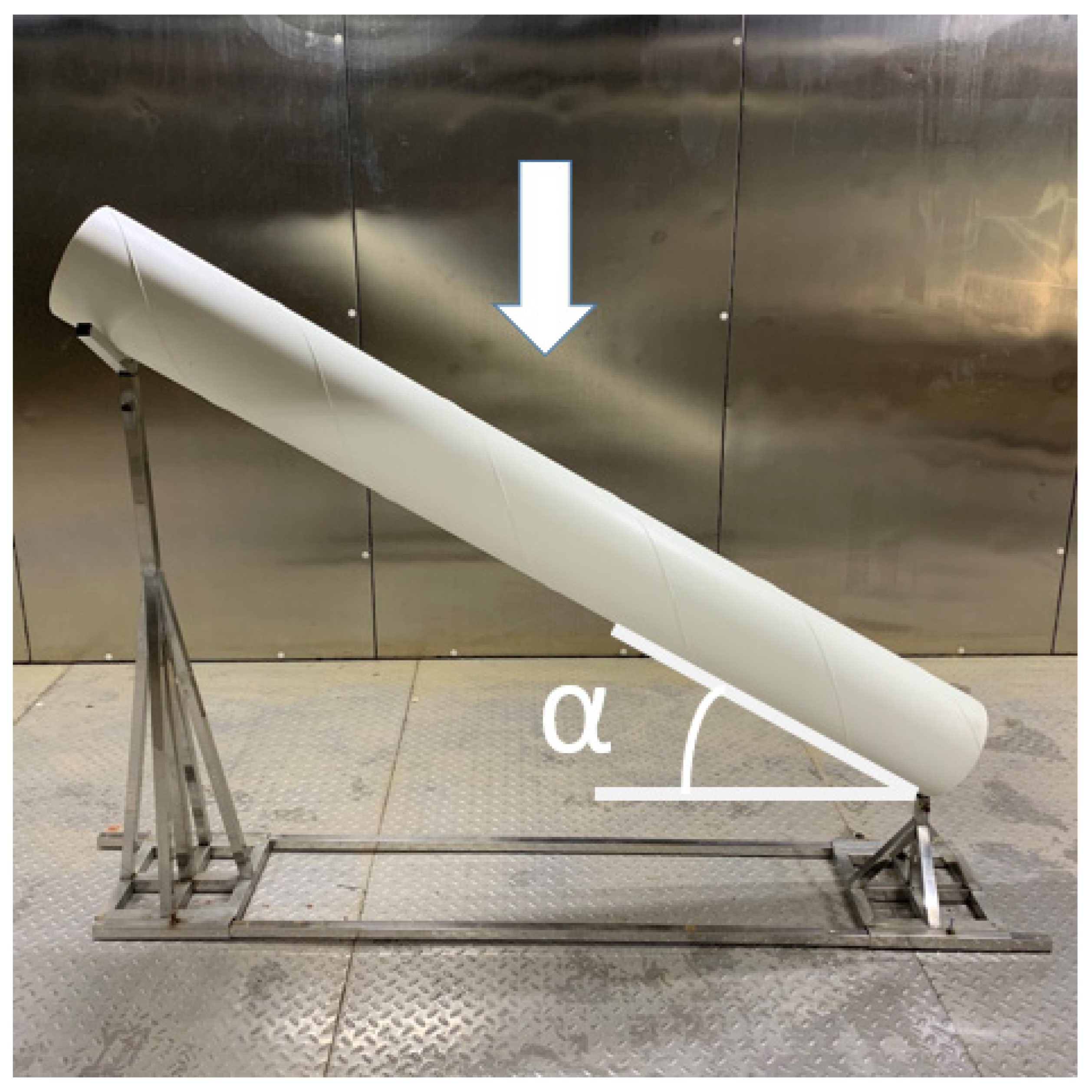
As shown in Figure 1, a piece of equipment called RHPW-60CT was used to control the testing temperature and humidity, which had external dimensions of 10 m long, 5 m wide, and 2.8 m high. The equipment could produce a lowest temperature of −60 °C. As shown in Figure 2, the stay cable support platform was located on the floor of the laboratory and could support a stay cable with an inclination angle between 0° and 60°, making its inclination angles 0°, 30°, 45°, and 60°. The cable model was made of high-density polyethylene (HDPE) with a smooth, exposed surface, which is the same material used to cover the exterior of bridge indentured cables most commonly used in practice [18,19]. The outer jacket of the cable was two meters long, and the diameters were D1 = 200 mm, D2 = 235 mm, and D3 = 315 mm, respectively. The stayed cable sheath used had a helix with an inclination angle of 45°, a cross-section width of 2.5 mm, and a height of 2.5 mm.
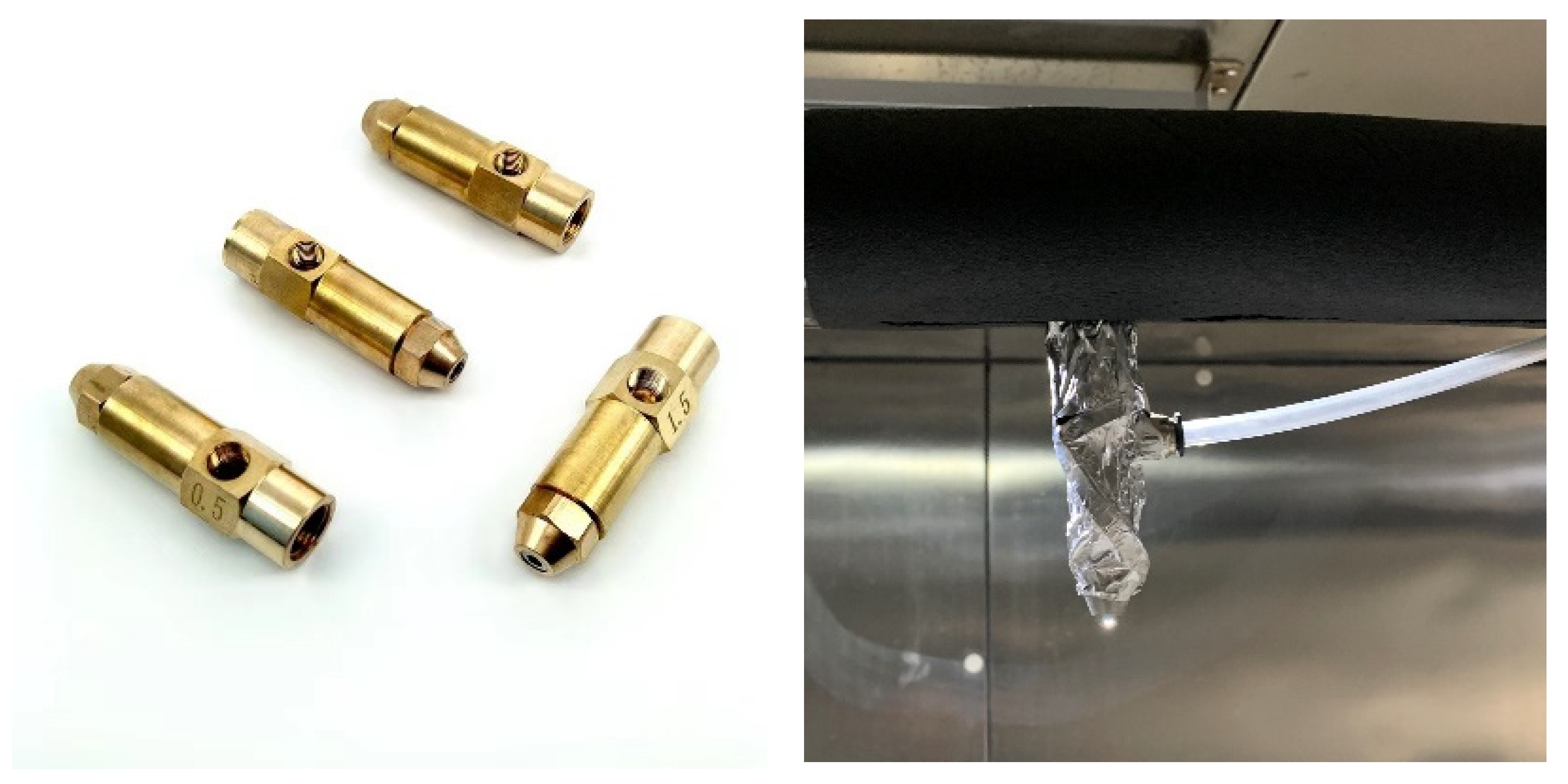
In order to simulate atmospheric icing, a spray device was installed in the cryogenic laboratory to simulate the sensation by injecting vertically falling precooled atomized droplets into the cold air. The spray nozzle was located near the ceiling of the cold store and was used to generate rainfall of specified intensity and range. As shown in Figure 3, the spray unit used a pneumatic nozzle with a nozzle diameter of 0.5 mm, a spray flow rate range of 0–3 L/min, and a chiller to enable the water temperature to be controlled over a range of 3 ± 0.5 °C. The spray unit covered an area of approximately 3.0 m × 6.0 m at the level of the laboratory floor. In order to achieve a more uniform spray intensity, a diagonal cable support device was placed in the middle of the spray area. The test was carried out under calm (wind-free) conditions to eliminate the effect of wind on the icing of cables. Before the icing test, the cable model was precooled to bring its surface temperature into thermal equilibrium with the set environment in the laboratory. The dynamic ice accumulation process during the tests lasted 60 min, and the following data were collected after each test: the number of icicle streaks formed, the maximum icicle streak length, and the ice rib width. The surface feature of the cable sides was recorded by taking photographs.

3. Results and Discussion

3.1. Formation of Ice on the Surface of the Cable

At the experiment’s beginning, the model’s surface temperature was consistent with the ambient air temperature. The overcooled water droplets hitting the surface of the stay cable were entirely or partially frozen on the surface to form ice. Meanwhile, the latent heat released by freezing helped some water droplets form a flowing water layer to adhere to the top of the ice sheet, providing raw materials for accumulating the lower ice. The latent heat generated was transmitted to the surrounding air through the ice–water interface, also known as recondensation [20]. As the downstream distance increased, the surface of the stay cable became less efficient at collecting water and freezing, which kept the underside relatively cool. The discontinuity and randomness of ice accumulation caused by the nonuniform surface temperature and high water mobility led to the abnormal accumulation of local ice, contributing to the formation of ice ribs and ice ridges.
Figure 4 shows the icing on the side of the stay cable under different temperatures and inclination angles. Under the condition of −5 °C, the arrangement of ice ribs formed at the bottom of the cable was more regular. At this time, the dominant icing path between the ice ribs was still forming, and the interval of the ice rib distribution was more uniform, the ice formed was small, and the number was relatively small. With the decrease in temperature, the icing on the lower part of the stay cable increased. The observation shows that the ice rib accumulation did not appear on the bottom surface of the stay cable until a certain period after the beginning of icing because the surface temperature of the stay cable was low at the beginning; water droplets can quickly solidify into ice after hitting the upper surface. The thickness of the ice accumulation on the stay cable surface increased with time, and the heat released in the freezing process caused the surface temperature of the stay cable to rise [21]. Some unfrozen droplets gathered on the surface and spread out to form a water film. The edge of the water film pushed further downstream, and in this process, the thickness of the water film decreased as it was transported downstream [22]. With the increase of the coverage of the water film, water droplets separated from the water film under the action of gravity, decomposed into multiple runoffs when flowing down the surface of the stay cable, and froze into ice further downstream. At this time, heat transfer with the air removed the remaining latent heat of melting in the water [23,24] and then froze part of the runoff into a rib-like ice structure. This process prevented the ice thickness on the upper surface of the cable from increasing continuously. The formation of ribbed ice increased the surface of the ice structure, enhanced heat exchange with the air, and promoted the rapid growth of the side ice structure. At the same time, under the influence of gravity and surface friction, some large liquid droplets that were not entirely solidified flowed downward along the cable surface in an elliptical path and gradually broke away from the cable surface to form ice edges. At the top of the ice edge was a thin layer of ice covered with liquid water, so the latent heat of melting released by the ice under the water film when it froze had to be removed from the ice–water boundary. Therefore, the temperature gradient from the ice surface to the environment controlled the ice growth rate [3].
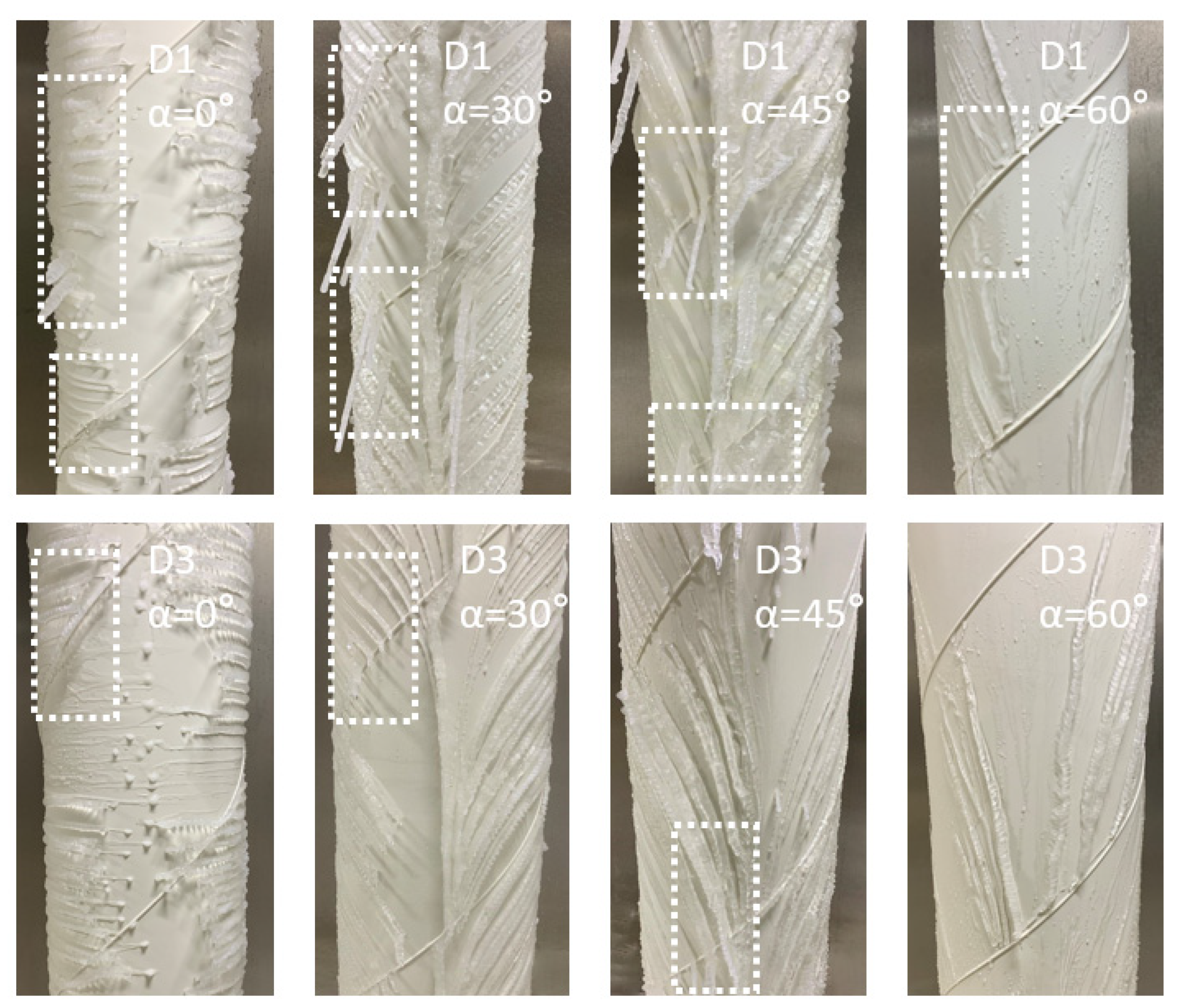
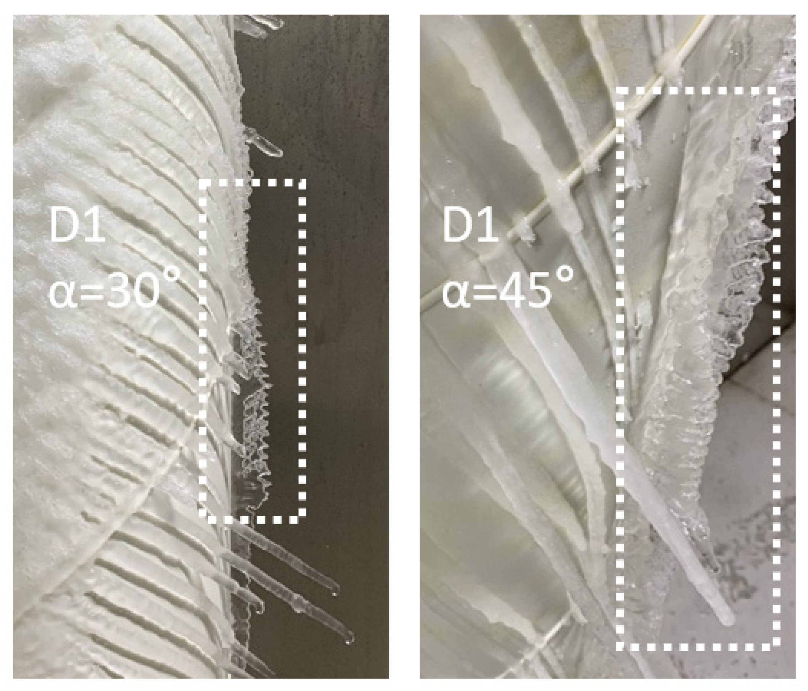
Figure 5 shows the freezing condition of the bottom surface of the stay cable under different diameters and inclination angles after freezing for 60 min at the ambient temperature of −25 °C. As can be clearly seen in Figure 5, the presence of spiral fillets changed the path of runoff on the cable surface. Unfrozen water was forced to flow and freeze along the upper edge of the spiral fillets, strengthening the interconnections between the ice ribs and forming irregular ice structures at the helix. It can be seen from Figure 3 that the ice structure shape at the helix varied according to the position of the helix on the cable surface. Ice edges are more likely to form on the side of the helix that obstructs water flow. On the smooth surface, water condensed into ice ribs on both sides and then continued to flow downward along the bottom of the stay cable away from the surface. It is worth noting that the ice ribs at the bottom of the stay cable converged to form banded ice at ambient temperatures of −25 °C, 30°, and 45° angles, and the top of the ice was zigzag, as shown in Figure 6. The conditions of low temperature and appropriate inclination angle contributed to this phenomenon.
During the dynamic accretion process of ice, the change of the cable surface (smooth plane–spiral fillet–smooth plane) dramatically influences the dynamic accretion process of ice. It was found that the ice accumulation in the lower part is closely related to laboratory temperature, cable diameter, and angle. Through the subsequent quantitative analysis of these conditions, we can have a clearer understanding of the bottom ice accumulation and provide a constructive reference for optimizing the stay cable ice accumulation model and the subsequent installation of deicing facilities.

3.2. The Effect of Temperature on Bottom Icing Conditions

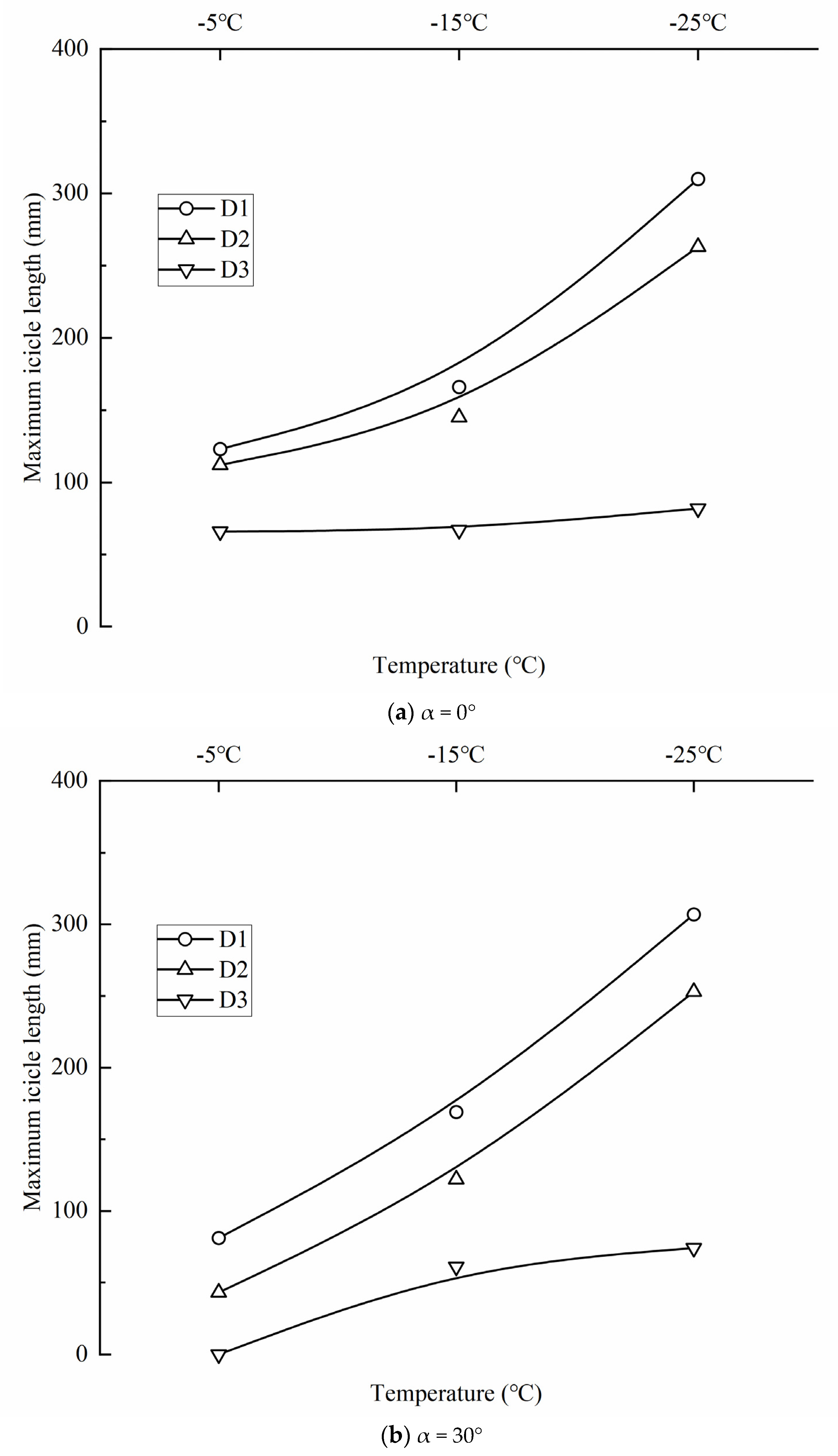
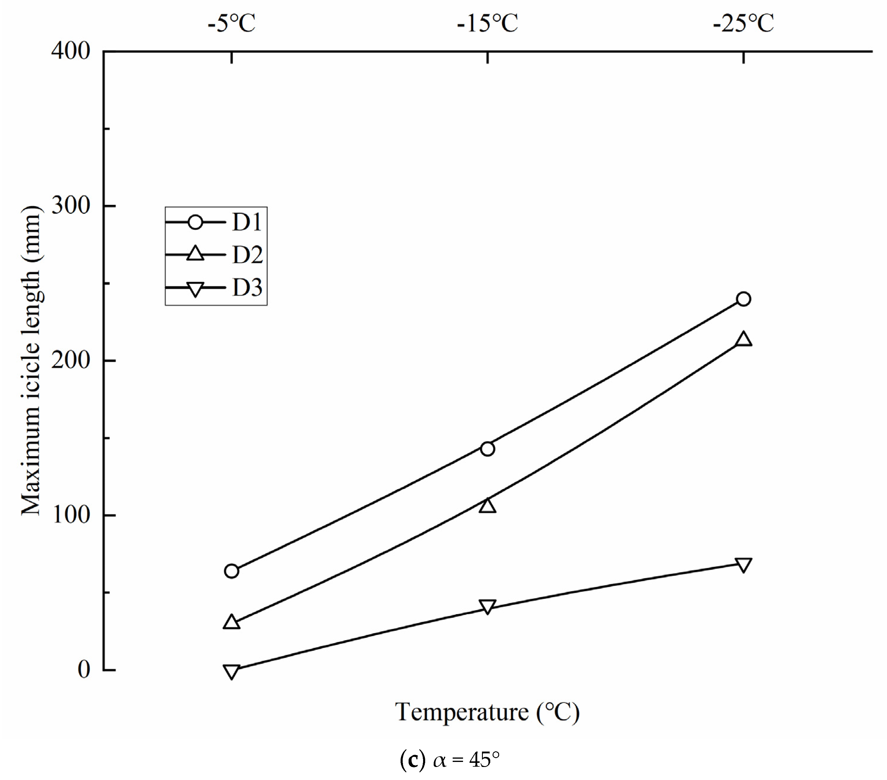
In order to quantify the effect of ambient temperature on the length of the maximum icicle, the trend of the top icicle length with temperature is shown in Figure 7. The length of each icicle in the graph represents the distance from the surface of the cable to the top of the icicle at different locations, the zero point of the vertical coordinate corresponds to the case where no icicle is present, and the horizontal coordinate corresponds to the different inclination angles of the cable. As can be seen from the above graph, for the same inclination of the cable, the maximum icicle length increases as the ambient temperature decreases; from −5 °C to −25 °C, the rate of increase in the maximum icicle length varies between 152.03% and 610% for the lower part of D1 and D2, while the net increase in the maximum icicle length for the lower part of D3 varies between 12 and 74 mm. This indicates a negative and significant correlation between ambient temperature and maximum icicle length. The low temperature allows more water droplets to collect in the lower part, and the gradually increasing icing surface further increases the heat transfer area between the ice structure and the air, which facilitates the accumulation of more ice structures at the bottom of the diagonal cable. Meanwhile, it can be seen that the icing of the bottom surface of the larger-diameter cable is less influenced by temperature.
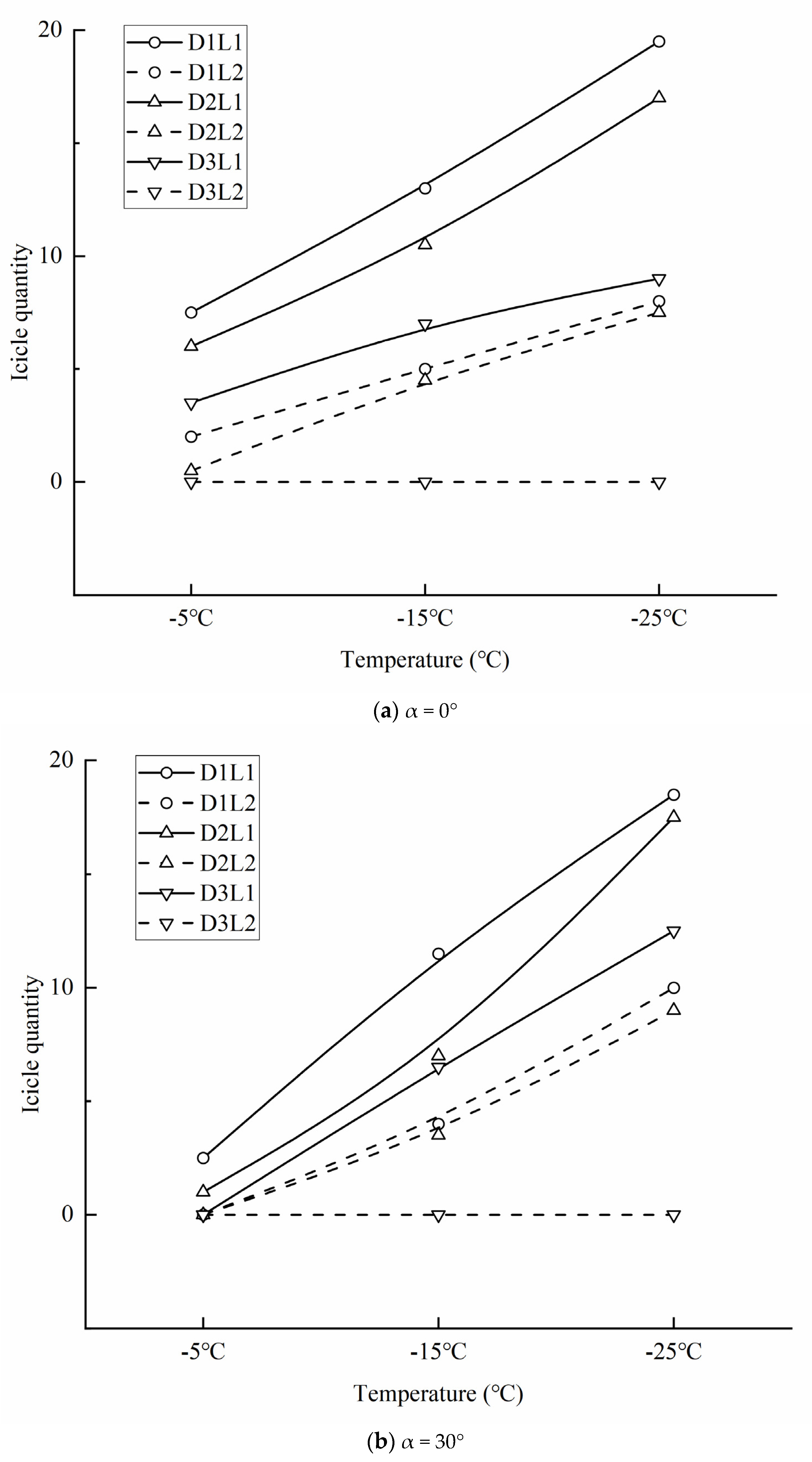
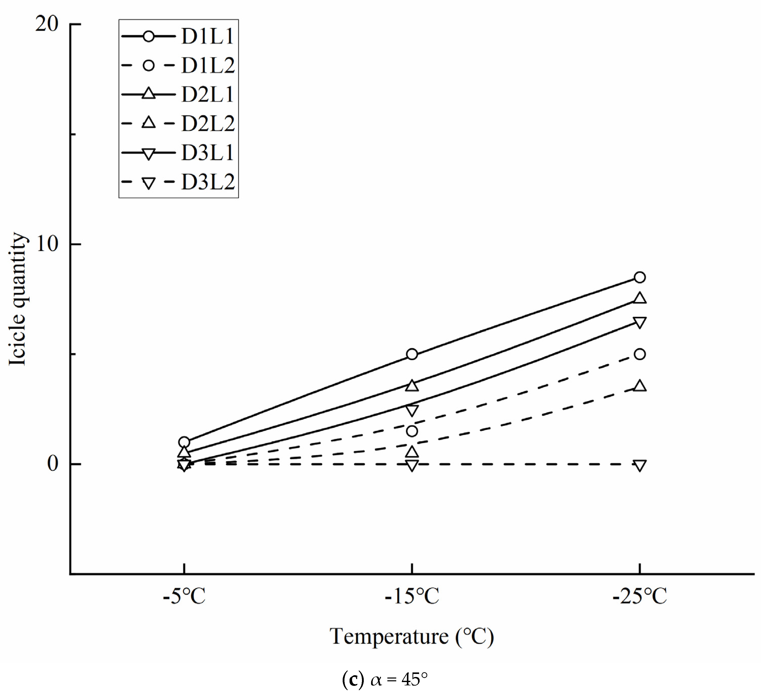
The more ice formed on the stay cable, the greater the lower cover when the ice falls off, which, to a certain extent, increases the risk of traffic safety below. In order to analyze the influence law of ambient temperature on the icicle, the inclination angle of the stay cable was kept unchanged in the quantitative test, and the variation trend of the icicle quantity with temperature is shown in Figure 8a–c. Under the same inclined angle of the cable (2 m), the number of icicles increases with the decrease in the ambient temperature. When the temperature decreases from −5 °C to −25 °C, the growth rate of the number of icicles in D1 varies from 160% to 750%. The growth rate of the number of icicles in D2 ranges from 183.3% to 1400%. For D3, the increased value of icicle quantity with L < 100 mm is 11~25. The results show a negative correlation between the ambient temperature and the number of icicles. In most cases, the amount of icicle in L < 100 mm (i.e., L1) is more than 1.7 times that in L ≥ 100 mm (i.e., L2). Under the same pipe diameter condition, the growth rate of the number of tiny icicles is often greater than that of large icicles. This is because the existence of water film on the ice surface makes the liquid water inside icicles only transfer heat upward through the icicle root [25]. In this case, the temperature transfer law determines the relationship between the increase in the number of icicles with the decrease in temperature.
In the icing phenomenon, the water film often develops laterally in the plane after accumulation. When the ice rib is formed, water droplets gather into the water flow and gradually freeze during the flow process. In this process, the width and thickness of water droplets increase continuously, forming a cylindrical ice structure distributed on both sides of the stay cable in the shape of ribs. The size of the ice ribs formed in the freezing process of the stay cable is roughly the same, and most of the ice ribs are formed on the windward side [26]. When the ambient temperature is −25 °C, the ice rib of the cable will further develop into banded ice at the bottom, which is facilitated by low temperature and appropriate inclination angle conditions.
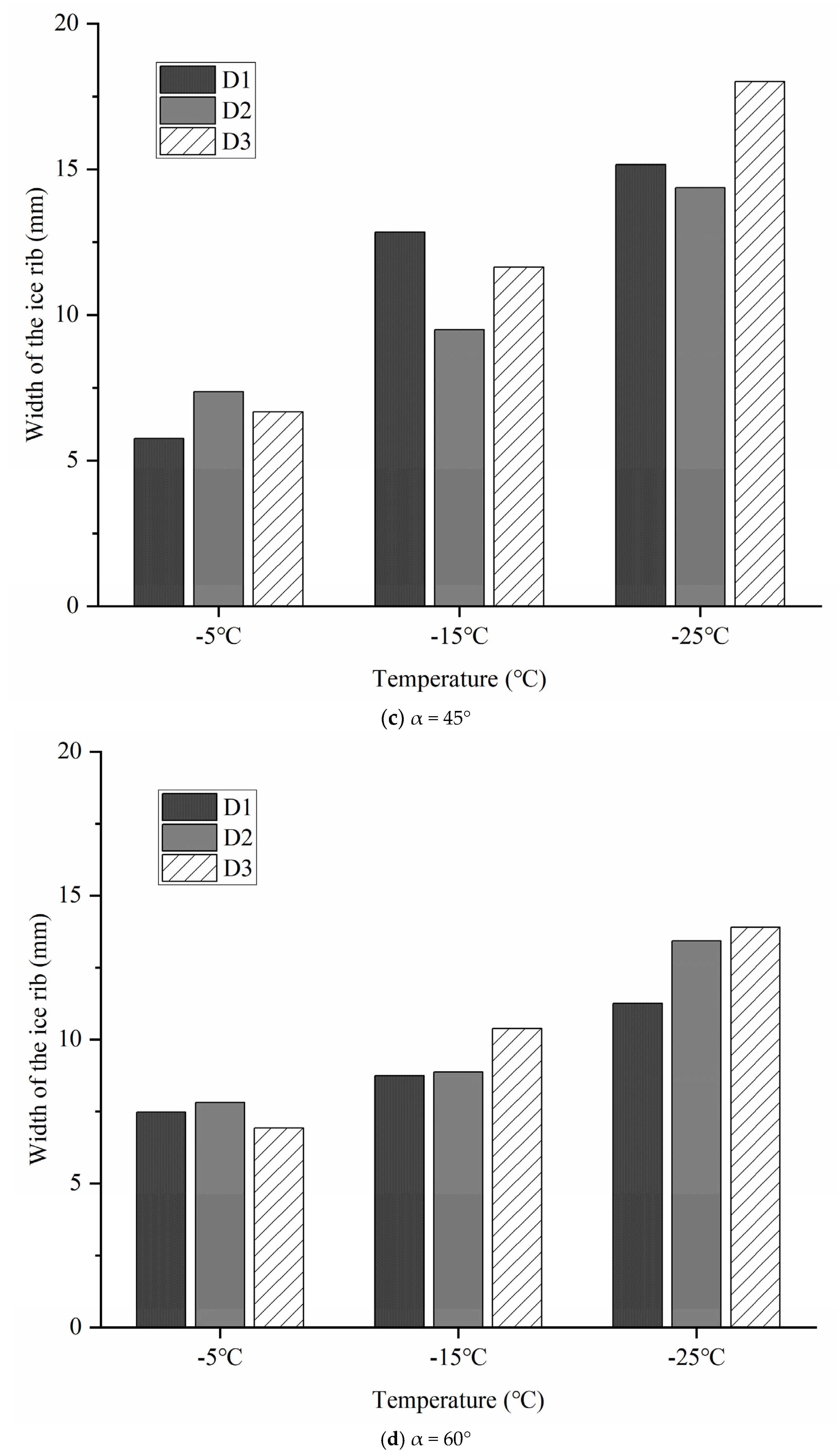
The width of each ice rib in Figure 9a–d represents the width distance from the root of the ice rib, i.e., where the ice rib grows, with the zero of the vertical coordinate corresponding to the case where no ice rib appears and the horizontal coordinate is related to different ambient temperatures. The width of the ice ribs formed gradually increases with decreasing temperature at a given inclination angle, with the rate of increase ranging from 50.6% to 170%. It can be seen that lowering the temperature promotes the growth of ice ribs. This is because the release of latent heat in the dynamic freezing process will increase the surrounding surface temperature [22]. Under the same conditions, the lower ambient temperature will take away this part of heat faster and accelerate the growth of the ice rib of the stay cable.

3.3. Effect of Change of Inclination Angle and Diameter of Cable on Bottom Icing Condition

In Figure 10a–c, under the same temperature condition, the maximum length of the icicle decreases with the increase of the angle of the stay cable. When the inclination angle of the stay cable increases from 0° to 60°, the decrease of the maximum length of the icicle varies from 66 mm to 310 mm and decreases to 0 when the inclination angle is 60°, which indicates that the increase of the inclination angle will reduce the length of the bottom icicle, that is, too large an inclination angle will inhibit the growth of the icicle. This is because an increase in inclination will reduce the mass of the intercepted droplets, so the amount of liquid water that can reach the bottom area of the stay cable will decrease [14]. That is, the droplet impingement surface reduces, and the droplet flows inertia on the surface of the stay cable increases. As a result, the droplet collection efficiency on the surface of the stay cable decreases, and the amount of water that can reach the bottom falls.
Additionally shown in Figure 10a–c, under the same temperature, the maximum length of the icicle decreases between 112 mm and 310 mm in D1 and D2 with the increase of angle, while the maximum length decreases between 66 mm and 82 mm in D3. It can be seen that the change in the cable diameter will also affect the maximum length of the icicle because the decrease in the cable diameter will increase the droplet collision efficiency. Mohammadian et al. [27] pointed out in their analysis of the icing flow field that for a cylinder with a large diameter, the resistance of the droplets overcomes the inertial force, which makes them more inclined to follow the airflow line and bypass the cylinder.
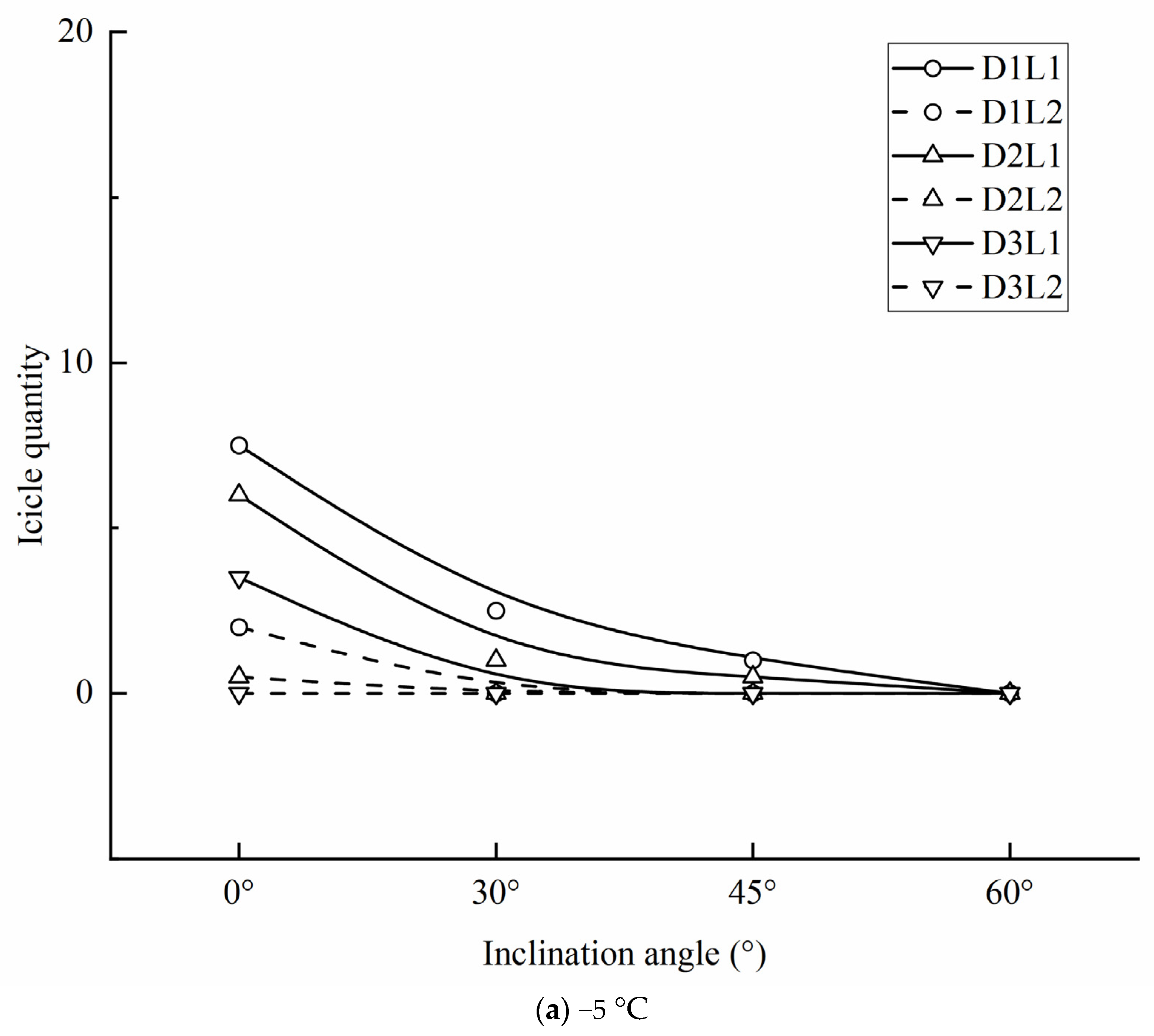
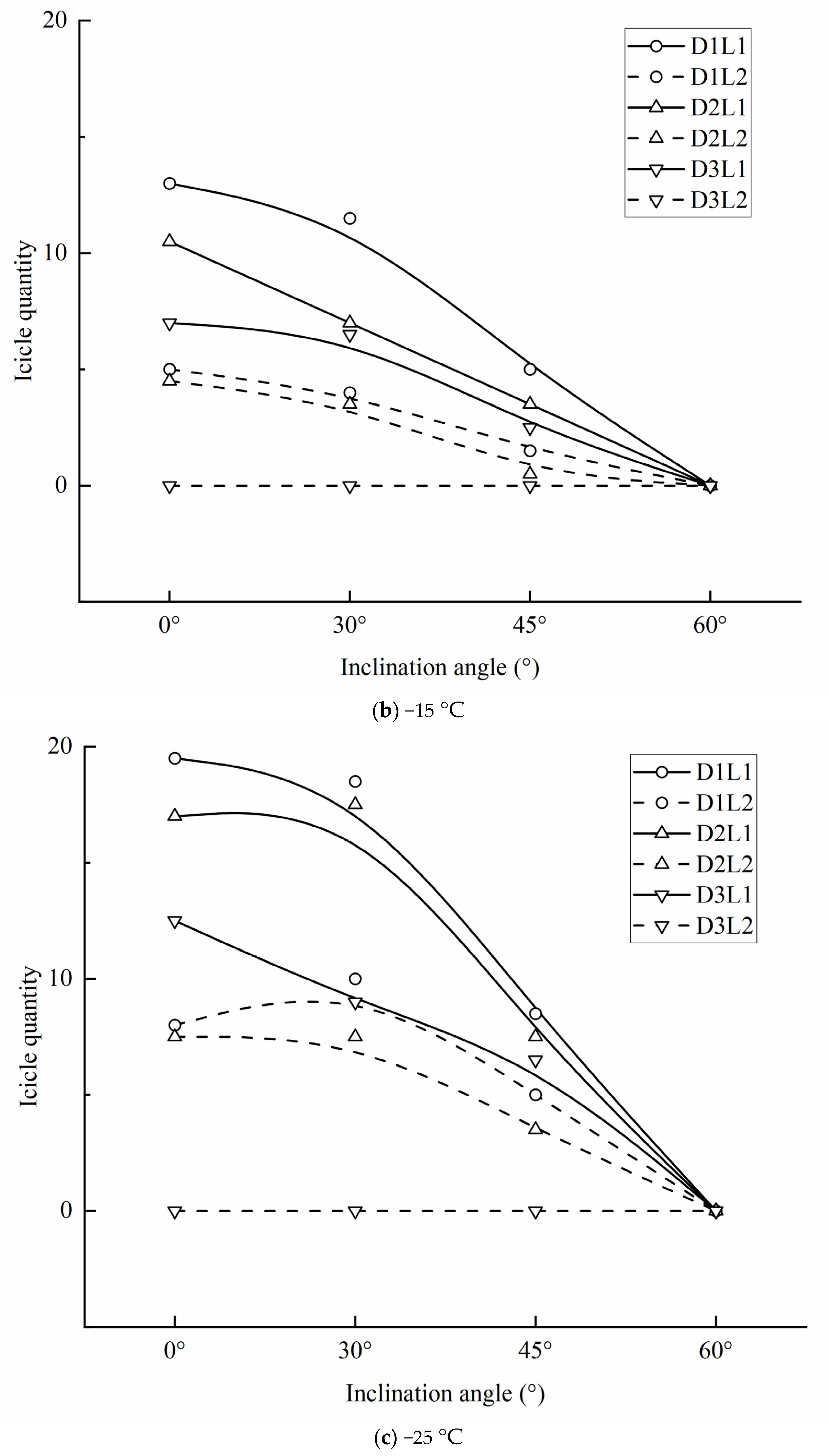
Figure 11 shows the trend of the number of icicles changing with the inclination angle and diameter of the stay cable when the ambient temperature remains unchanged. It can be seen that, under the same ambient temperature conditions, the number of icicles gradually decreases as the inclination angle of the cable (2 m) increases; as the inclination angle of the cable increases from 0° to 60°, the reduction in the number of D1 icicles varies from 19 to 55, and the decrease in the number of D2 icicles varies from 13 to 49. The reduction in the number of D3 icicles varies from 7 to 18, no L2 icicles appear at any time, and no icicles are formed when the inclination angle is 60°. This indicates that the increase in the angle of inclination inhibits the growth of icicles to some extent. This phenomenon was also verified by Abdelaal et al. [28]. The increase in inclination angle leads to an increase in the effective impact velocity of the droplets, resulting in a decrease in ice accumulation in the upper part [29,30,31,32]. The lower piece of the inclined rope does not have access to sufficient material, thus inhibiting ice formation on the bottom surface.
In Figure 11, the smaller the diameter, the greater the number of icicles formed for a given inclination of the diagonal cable, and, again, more icicles were formed for L ≥ 100 mm. In the studies by Szilder [33] and Mohammadian et al. [27], appropriate inclination angles and smaller diameters helped to increase the efficiency of droplet collision with the sloping cable surface, which, to some extent, increased the efficiency of liquid water collection on the cable surface, which in turn increased the water supply to the bottom surface, allowing the number of icicles to increase.

4. Conclusions

The test was carried out under specific low-temperature laboratory conditions, and the obtained icing results may also be affected by the high-density polyethylene (HDPE) material on the cable surface.
(1) The growth of the ice rib is mainly affected by temperature, and the width of the ice ribs increases continuously as the temperature decreases. However, the width of the ice rib is less affected by the inclination angle and diameter of the stay cable.
(2) The change in inclination angle has a particularly pronounced effect on the lower part of the cable. With the increase of inclination angle, the maximum length and number of icicles at the bottom of the stay cable will decrease. Therefore, the bottom area of the stay cable with inclination of α < 60° is the main area of anti-icing and deicing.
(3) The amount of ice accumulation in the lower part of the cable decreases with increasing diameter of the cable, and the increase in the diameter can effectively reduce the formation of icicles in the lower leg. Therefore, smaller-diameter cables are more prone to ice accumulation at the bottom.
(4) Ambient temperature is an essential factor influencing ice accumulation in the lower part of the cable. The maximum length of icicles in the lower part of the cable increases linearly with decreasing temperature. Lower temperatures create more icicles at the bottom of the stay cables.
In future work, we plan to expand the icing test and add more environmental factors to include a wider range of icing conditions and icing shape changes. In addition, by changing the surface material and surface roughness of the stay cable, the icing results obtained can be promoted to a greater extent. We also plan to study the deicing facilities based on the obtained test results to provide assistance for cable deicing.

Author Contributions

Writing—original draft preparation, Z.G.; writing—review and editing, W.L.; project administration, H.X.; software, Y.P.; data curation, K.Y. All authors have read and agreed to the published version of the manuscript.

Funding

The authors appreciate the financial support from Joint Funds of the Natural Science Foundation of Hubei Province (No. 2022CFD130), the Key Research and Development Program of Hubei Province (No. 2021BGD015), and the Knowledge Innovation Project of Wuhan (No. 2022010801010259).

Institutional Review Board Statement

Not applicable.

Informed Consent Statement

Not applicable.

Data Availability Statement

The data presented in this study are available on request from the corresponding author.

Conflicts of Interest

The authors declare no conflict of interest.

References

  1. Jung, H.J.; Yang, T.H.; Jang, B.S. Field application of a robotic system on cable stays of incheon bridge for snow removal. Paper presented at: ISARC 2011. In Proceedings of the 28th International Symposium on Automation and Robotics in Construction, Seoul, Republic of Korea, 29 June–2 July 2011. [Google Scholar]
  2. Oohira, T.; Tanaka, Y.; Ishimoto, K.; Sato, S. Predicting snow falling from cables of a cable-stayed bridge. Paper presented at: IWAIS 2007. In Proceedings of the 12th International Workshop on Atmospheric Icing of Structures, Yokohama, Japan, 9–12 October 2007. [Google Scholar]
  3. Makkonen, L. Models for the growth of rime, glaze, icicles and wet snow on structures. Philos. Trans. R. Soc. London. Ser. A Math. Phys. Eng. Sci. 2000, 358, 2913–2939. [Google Scholar] [CrossRef]
  4. Farzaneh, M. (Ed.) Atmospheric Icing of Power Networks; Springer Science & Business Media: Berlin/Heidelberg, Germany, 2008. [Google Scholar] [CrossRef]
  5. Nims, D.K.; Hunt, V.J.; Helmicki, A.J.; Ng, T.M.T. Ice Prevention or Removal on the Veteran’s Glass City Skyway Cables; No. FHWA/OH-2014/11; The National Academies of Sciences, Engineering, and Medicine: Washington, DC, USA, 2014. [Google Scholar]
  6. De Gregorio, F.; Ragni, A.; Airoldi, M.; Romano, G.P. PIV Investigation on Airfoil with Ice Accretions and Resulting Performance Degradation. In ICIASF 2001 Record, 19th International Congress on Instrumentation in Aerospace Simulation Facilities (Cat. No. 01CH37215); IEEE: New York, NY, USA, 2001; pp. 94–105. [Google Scholar] [CrossRef]
  7. Waldman, R.; Liu, Y.; Zhang, K.; Hu, H. High-Speed Imaging to Quantify the Transient Ice Accretion Process on a NACA 0012 Airfoil. In 53rd AIAA Aerospace Sciences Meeting; American Institute of Aeronautics and Astronautics: Reston, VA, USA, 2015; p. 0033. [Google Scholar] [CrossRef]
  8. Zhang, K.; Wei, T.; Hu, H. An experimental investigation on the surface water transport process over an airfoil by using a digital image projection technique. Exp. Fluids 2015, 56, 173. [Google Scholar] [CrossRef]
  9. Makkonen, L.; Lozowski, E.P. Numerical Modelling of Icing on Power Network Equipment. In Atmospheric Icing of Power Networks; Springer: Dordrecht, The Netherlands, 2008; pp. 83–117. [Google Scholar] [CrossRef]
  10. Naterer, G.F. Coupled liquid film and solidified layer growth with impinging supercooled droplets and Joule heating. Int. J. Heat Fluid Flow 2003, 24, 223–235. [Google Scholar] [CrossRef]
  11. Lébatto, E.B.; Farzaneh, M.; Lozowski, E.P. Conductor icing: Comparison of a glaze icing model with experiments under severe laboratory conditions with moderate wind speed. Cold Reg. Sci. Technol. 2015, 113, 20–30. [Google Scholar] [CrossRef]
  12. Peng, Y.; Veerakumar, R.; Liu, Y.; He, X.; Hu, H. An experimental study on dynamic ice accretion and its effects on the aerodynamic characteristics of stay cables with and without helical fillets. J. Wind. Eng. Ind. Aerodyn. 2020, 205, 104326. [Google Scholar] [CrossRef]
  13. Liu, Y.; Chen, W.; Peng, Y.; Hu, H. An experimental study on the dynamic ice accretion processes on bridge cables with different surface modifications. J. Wind. Eng. Ind. Aerodyn. 2019, 190, 218–229. [Google Scholar] [CrossRef]
  14. Szilder, K.; D’Auteuil, A.; McTavish, S. Predicting ice accretion from freezing rain on bridge stay cables. Cold Reg. Sci. Technol. 2021, 187, 103285. [Google Scholar] [CrossRef]
  15. Demartino, C.; Koss, H.H.; Georgakis, C.T.; Ricciardelli, F. Effects of ice accretion on the aerodynamics of bridge cables. J. Wind. Eng. Ind. Aerodyn. 2015, 138, 98–119. [Google Scholar] [CrossRef]
  16. Demartino, C.; Ricciardelli, F. Aerodynamic stability of ice-accreted bridge cables. J. Fluids Struct. 2015, 52, 81–100. [Google Scholar] [CrossRef]
  17. Górski, P.; Pospíšil, S.; Kuznetsov, S.; Tatara, M.; Marušić, A. Strouhal number of bridge cables with ice accretion at low flow turbulence. Wind. Struct. 2016, 22, 253–272. [Google Scholar] [CrossRef]
  18. Kleissl, K.; Georgakis, C.T. Comparison of the aerodynamics of bridge cables with helical fillets and a pattern-indented surface. J. Wind. Eng. Ind. Aerodyn. 2012, 104, 166–175. [Google Scholar] [CrossRef]
  19. Koss, H.; Lund, M.S.M. Experimental investigation of aerodynamic instability of iced bridge cable sections. In Proceedings of the 6th European and African Wind Engineering Conference Robinson College, Cambridge, UK, 7–11 July 2013. [Google Scholar]
  20. Hofmeister, W.H.; Bayuzick, R.J.; Robinson, M.B. Dual purpose pyrometer for temperature and solidification velocity measurement. Rev. Sci. Instrum. 1990, 61, 2220–2223. [Google Scholar] [CrossRef]
  21. Brassard, J.D.; Blackburn, C.; Toth, M.; Momen, G. Ice accretion, shedding, and melting on cable-stayed bridges: A laboratory performance assessment. Cold Reg. Sci. Technol. 2022, 204, 103672. [Google Scholar] [CrossRef]
  22. Gao, L.; Liu, Y.; Hu, H. An experimental investigation of dynamic ice accretion process on a wind turbine airfoil model considering various icing conditions. Int. J. Heat Mass Transf. 2019, 133, 930–939. [Google Scholar] [CrossRef]
  23. Zhang, K.; Hu, H. An experimental study on the transient behavior of wind-driven water runback over a flat surface. In Proceedings of the 54th AIAA Aerospace Sciences Meeting, San Diego, CA, USA, 4–8 January 2016; p. 1123. [Google Scholar] [CrossRef]
  24. Waldman, R.M.; Li, H.; Hu, H. An experimental investigation on the effects of surface wettability on water runback and ice accretion over an airfoil surface. In Proceedings of the 8th AIAA Atmospheric and Space Environments Conference, Washington, DC, USA, 13–17 June 2016; p. 3139. [Google Scholar] [CrossRef] [Green Version]
  25. Makkonen, L. A model of icicle growth. J. Glaciol. 1988, 34, 64–70. [Google Scholar] [CrossRef] [Green Version]
  26. Górski, P.; Tatara, M.; Pospíšil, S.; Trush, A. A new approach to registering ice covers simulated on a sectional model of a bridge stay cable in laboratory conditions. Measurement 2021, 179, 109500. [Google Scholar] [CrossRef]
  27. Mohammadian, B.; Sarayloo, M.; Abdelaal, A.; Raiyan, A.; Nims, D.K.; Sojoudi, H. Experimental and theoretical studies of wet snow accumulation on inclined cylindrical surfaces. Model. Simul. Eng. 2020, 2020, 9594685. [Google Scholar] [CrossRef]
  28. Abdelaal, A.; Nims, D.; Jones, K.; Sojoudi, H. Prediction of ice accumulation on bridge cables during freezing rain: A theoretical modeling and experimental study. Cold Reg. Sci. Technol. 2019, 164, 102782. [Google Scholar] [CrossRef]
  29. Makkonen, L. Modeling power line icing in freezing precipitation. Atmos. Res. 1998, 46, 131–142. [Google Scholar] [CrossRef]
  30. Makkonen, L. Modeling of ice accretion on wires. J. Appl. Meteorol. Climatol. 1984, 23, 929–939. [Google Scholar] [CrossRef]
  31. Szilder, K. Simulation of ice accretion on a cylinder due to freezing rain. J. Glaciol. 1994, 40, 586–594. [Google Scholar] [CrossRef] [Green Version]
  32. Lébatto, E.B.; Farzaneh, M.; Lozowski, E.P. Three-dimensional morphogenetic model of ice accretion on a non-rotating cylinder. In Proceedings of the 11. International Workshop on Atmospheric Icing of Structures (IWAIS 2005), Montreal, PQ, Canada, 12–16 June 2005. [Google Scholar]
  33. Szilder, K. Snow accretion prediction on an inclined cable. Cold Reg. Sci. Technol. 2019, 157, 224–234. [Google Scholar] [CrossRef]
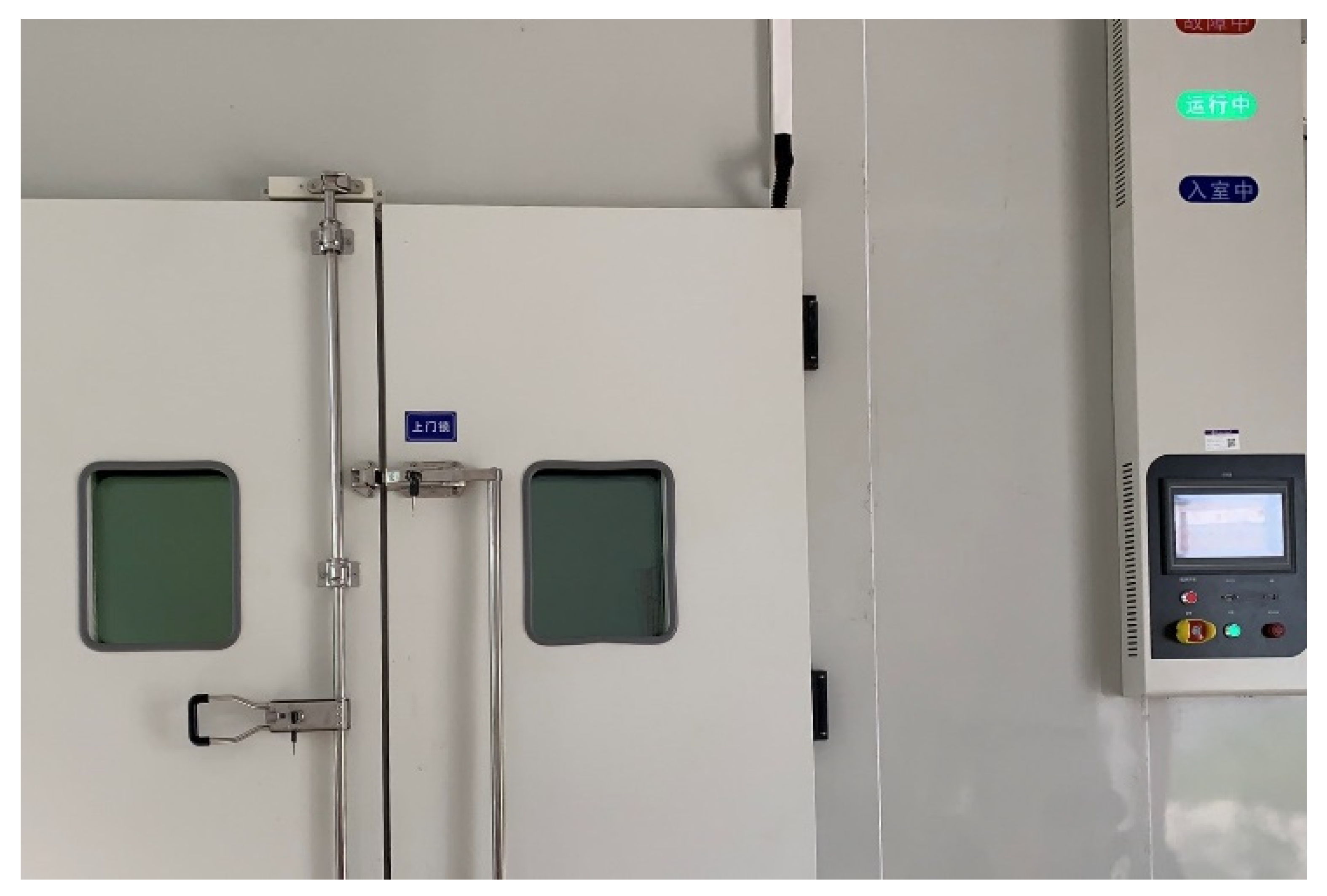
Figure 1. Climatic chamber rig.
Applsci 13 03963 g001
Figure 2. Climatic chamber rig with cables.
Applsci 13 03963 g002
Figure 3. Spray nozzle.
Applsci 13 03963 g003
Figure 4. Icing on the side of the cable under different temperature and inclination angle conditions.
Applsci 13 03963 g004
Figure 5. −25°, Icing conditions of the bottom surface under different diameters and inclination angles.
Applsci 13 03963 g005
Figure 6. Ice rib.
Figure 6. Ice rib.
Applsci 13 03963 g006
Figure 7. (ac) Influence of ambient temperature on maximal length of icicles.
Applsci 13 03963 g007aApplsci 13 03963 g007b
Figure 8. (ac) Influence law of temperature on icicles quantity (per meter).
Applsci 13 03963 g008aApplsci 13 03963 g008b
Figure 9. (ad) Influence of ambience on ice rib width.
Applsci 13 03963 g009aApplsci 13 03963 g009b
Figure 10. (ac) Influence of cable inclination angle on maximal length of icicles.
Applsci 13 03963 g010aApplsci 13 03963 g010b
Figure 11. (ac) Influence of cable inclination angle on the number of icicles (per meter).
Applsci 13 03963 g011aApplsci 13 03963 g011b
Disclaimer/Publisher’s Note: The statements, opinions and data contained in all publications are solely those of the individual author(s) and contributor(s) and not of MDPI and/or the editor(s). MDPI and/or the editor(s) disclaim responsibility for any injury to people or property resulting from any ideas, methods, instructions or products referred to in the content.