
Development of an In-Situ Simulation Device for Testing Deep Pressure-Preserving Coring Tools under High-Temperature and Ultrahigh-Pressure Conditions

Abstract
1. Introduction
2. Principle and Structure of the In-Situ Simulation Device for Deep Coring Tools
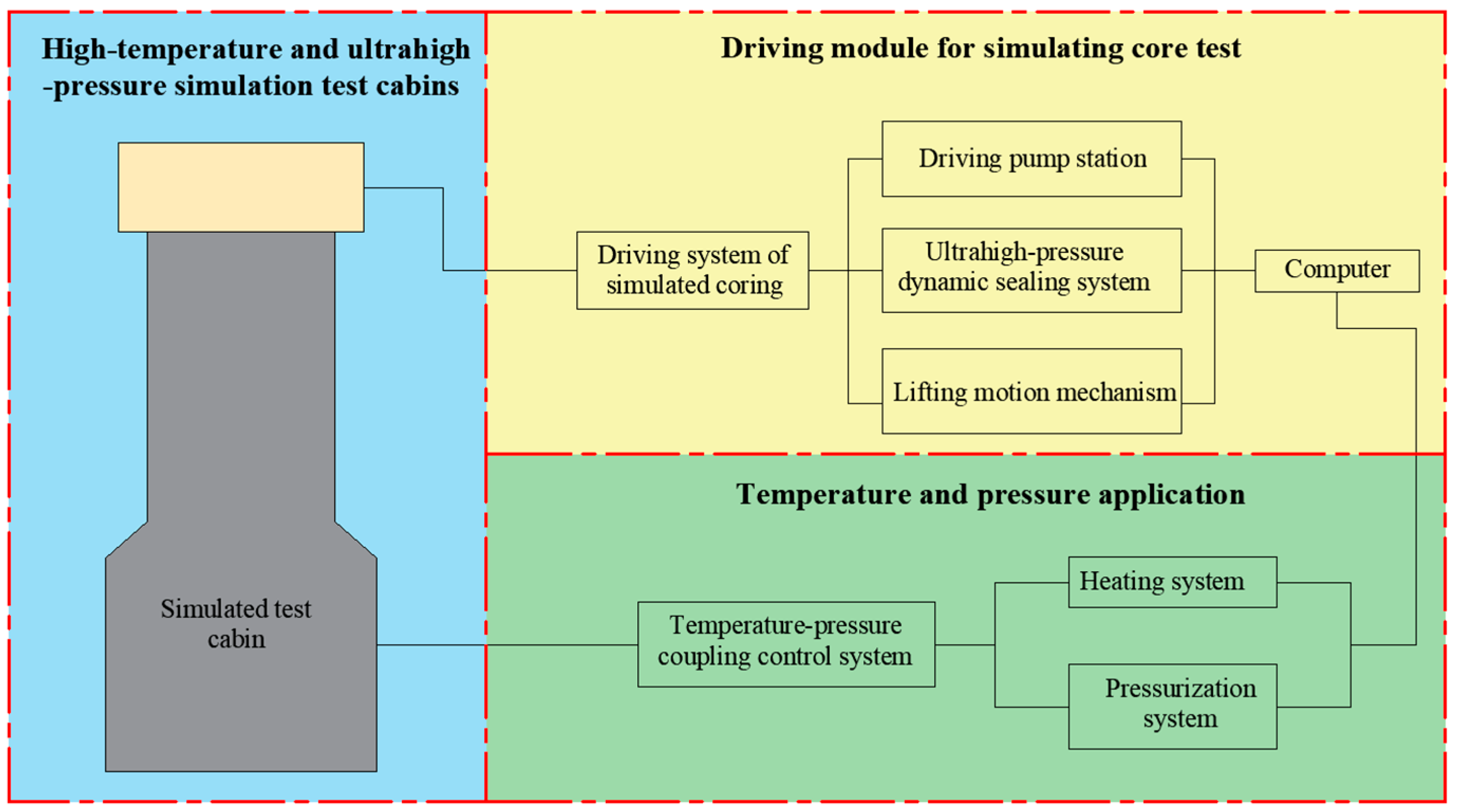
2.1. The Structure and Design Principle of the Device
- (1)
- Maximum working pressure of the test cabin: 140 MPa;
- (2)
- Maximum operating temperature of the test cabin: 150 °C;
- (3)
- Maximum working pressure of the driving module: 140 MPa;
- (4)
- Maximum rotation speed of the driving module: 150 r/min;
- (5)
- Inner diameter of the rock cabin: 500 mm;
- (6)
- Inner diameter of the drill pipe cabin: 150 mm.
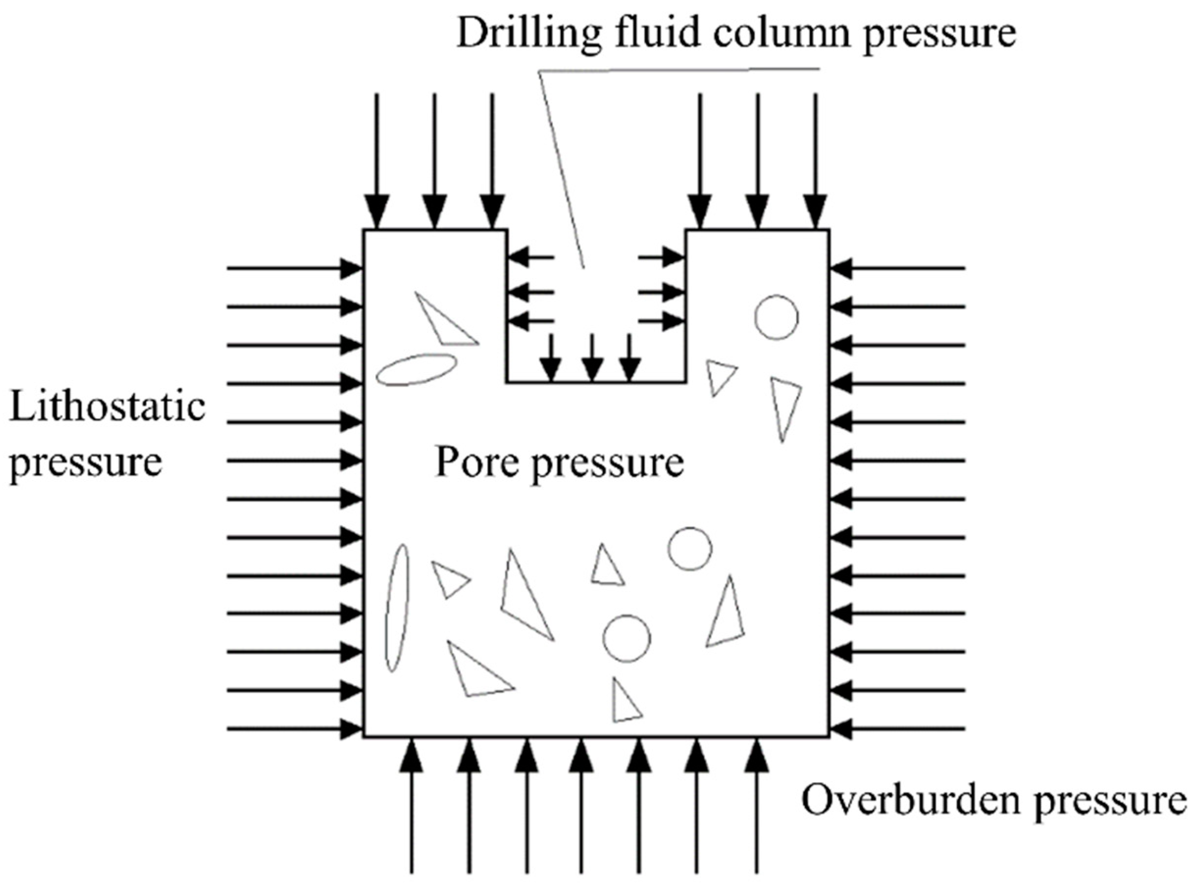
2.2. Principle of Temperature and Pressure Application
3. Analysis and Design of Key Components
3.1. High-Temperature and Ultrahigh-Pressure Simulation Test Cabin
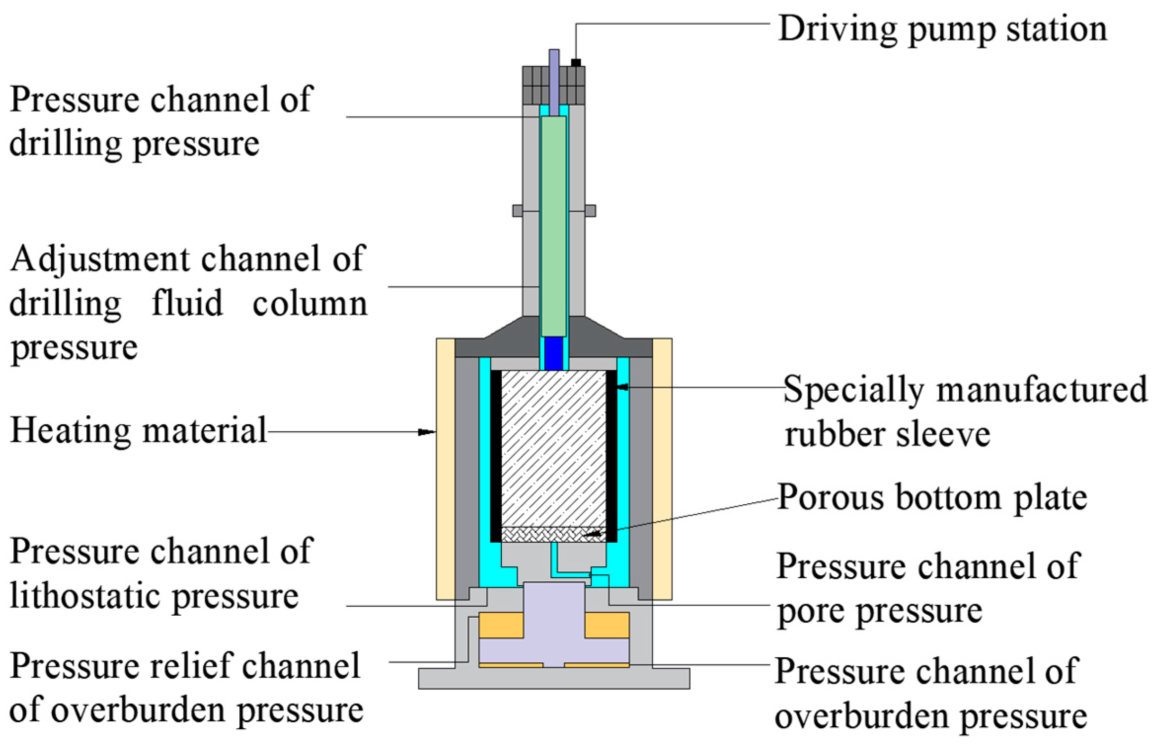
3.1.1. Overall Structure of the Simulation Test Cabin
3.1.2. The Structural Form of the Cabin
3.1.3. Analysis and Calculation of Wall Thickness
3.2. Driving Module for Simulating Coring Tests
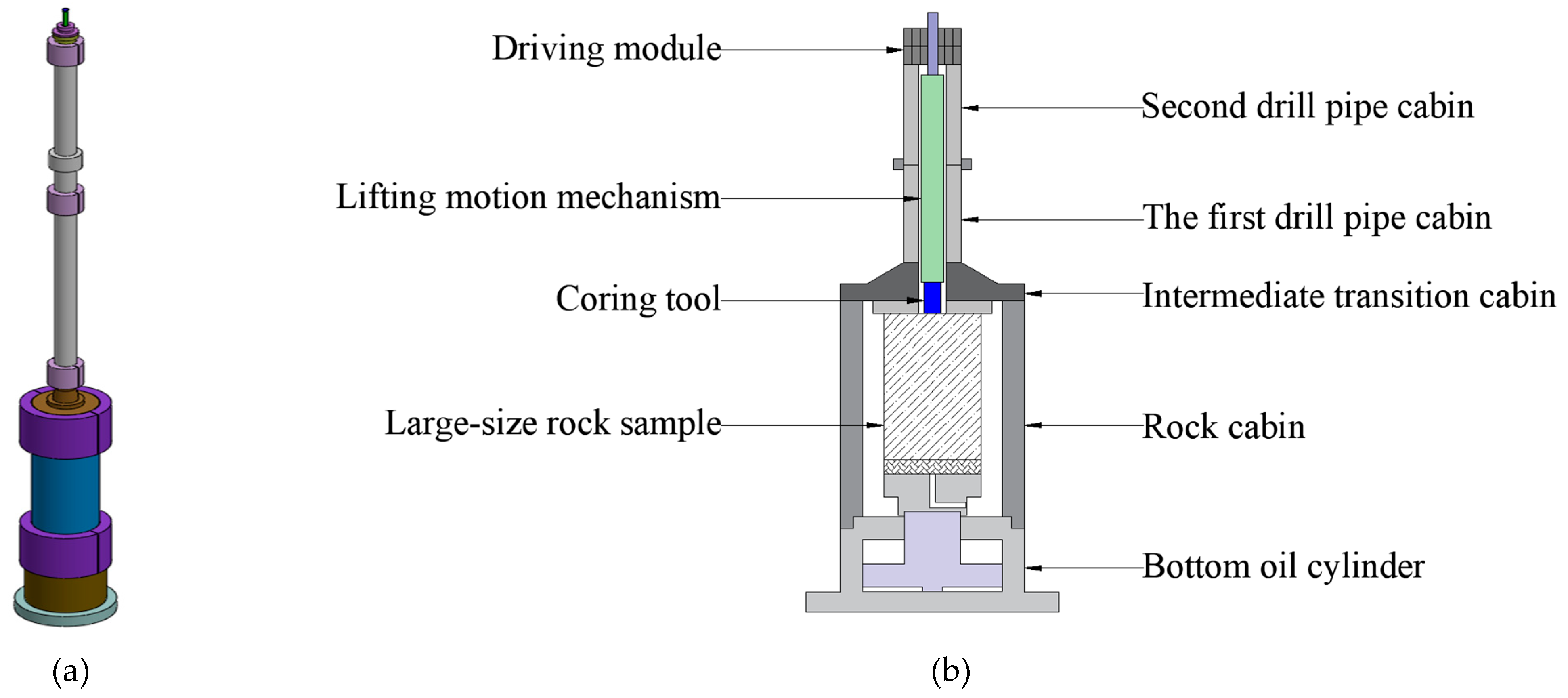
3.2.1. Structure and Working Principle of the Lifting Motion Mechanism
3.2.2. Composition of the Dynamic System
4. Experimental Study and Results Analysis of the Device
4.1. Pressure Testing and Results Analysis of the Test Cabin
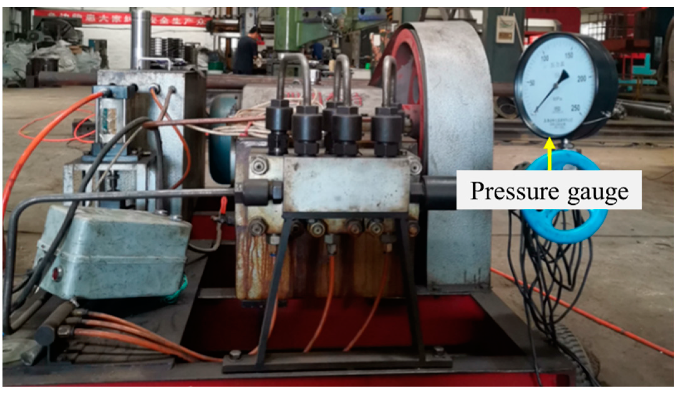
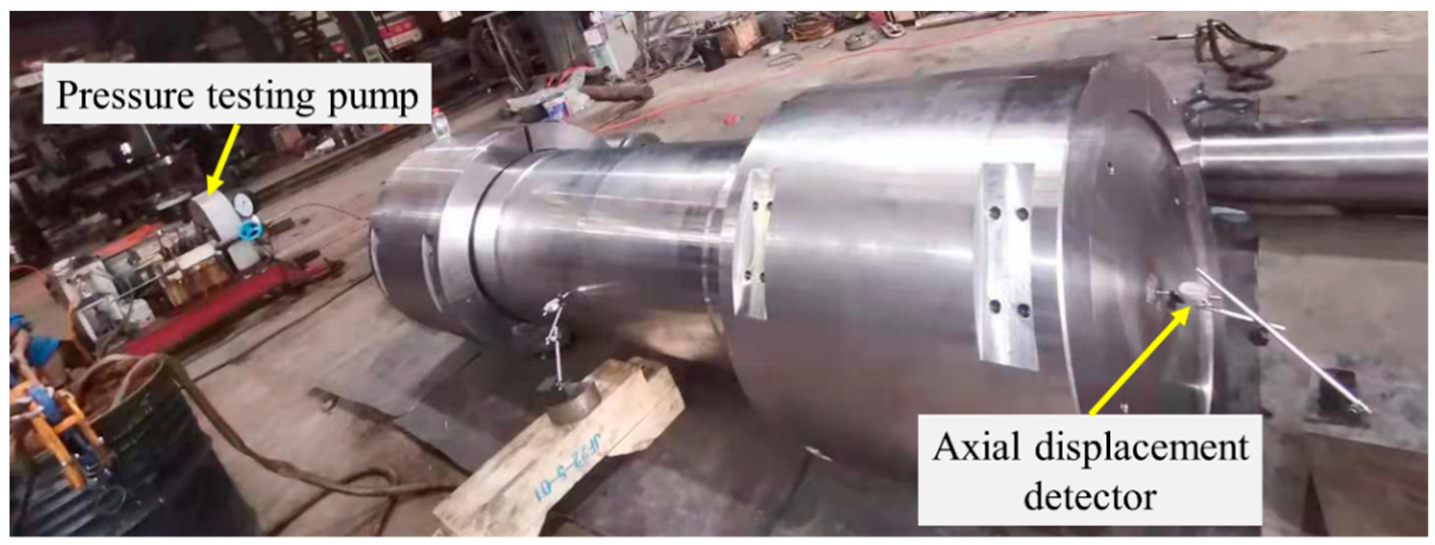
4.1.1. Pressure Testing of the Rock Cabin
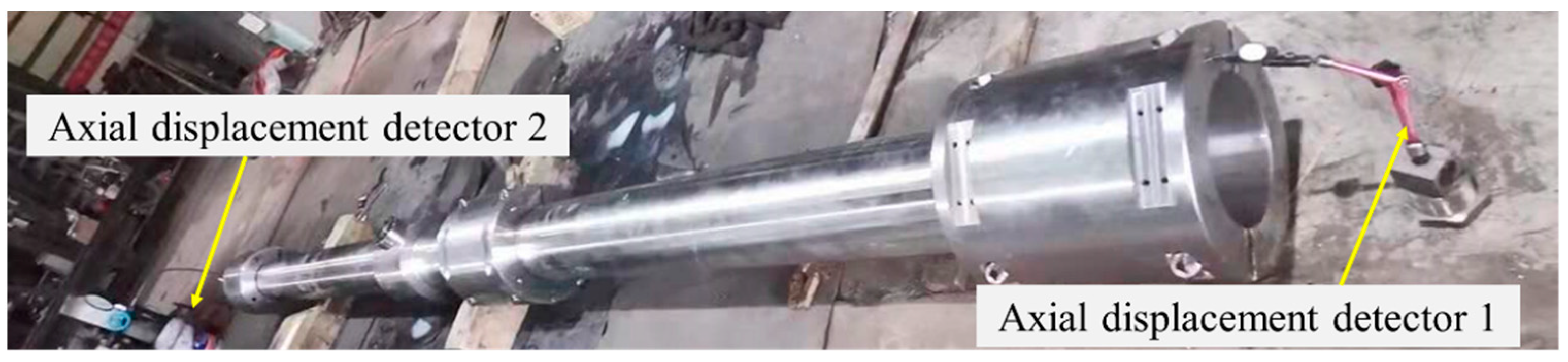
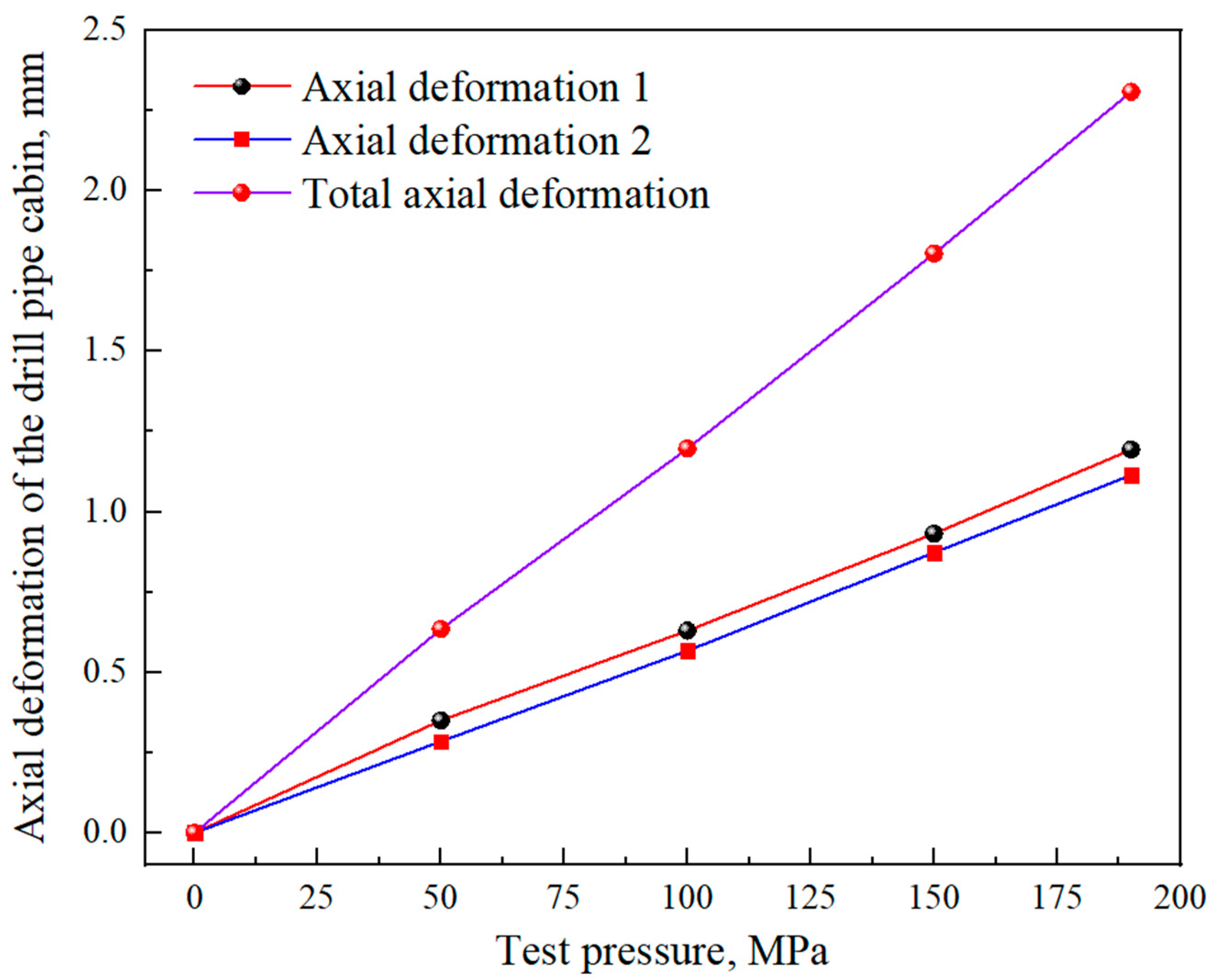
4.1.2. Pressure Testing of the Drill Pipe Cabin
4.2. Experimental Study of the Driving Module
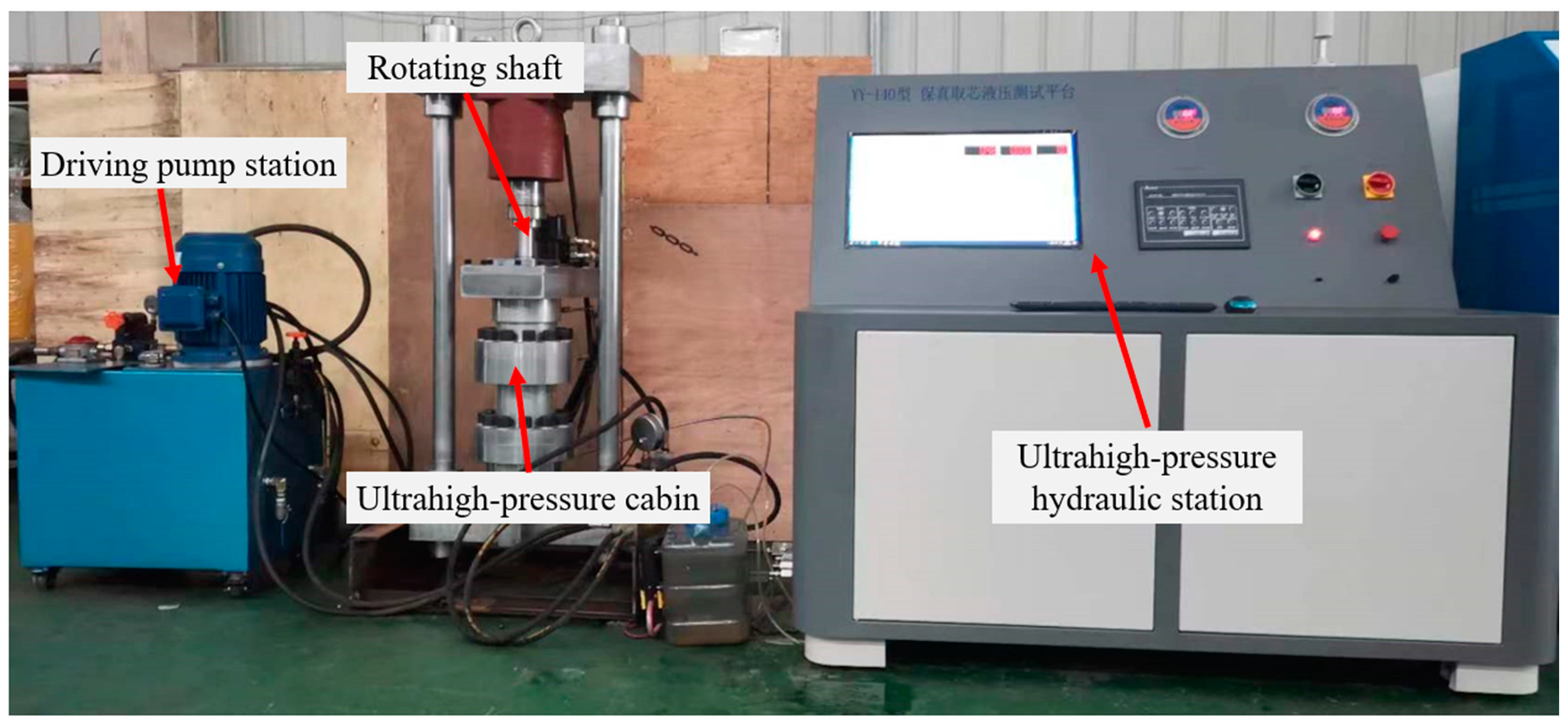
4.2.1. The Composition and Working Principle of the Experimental System
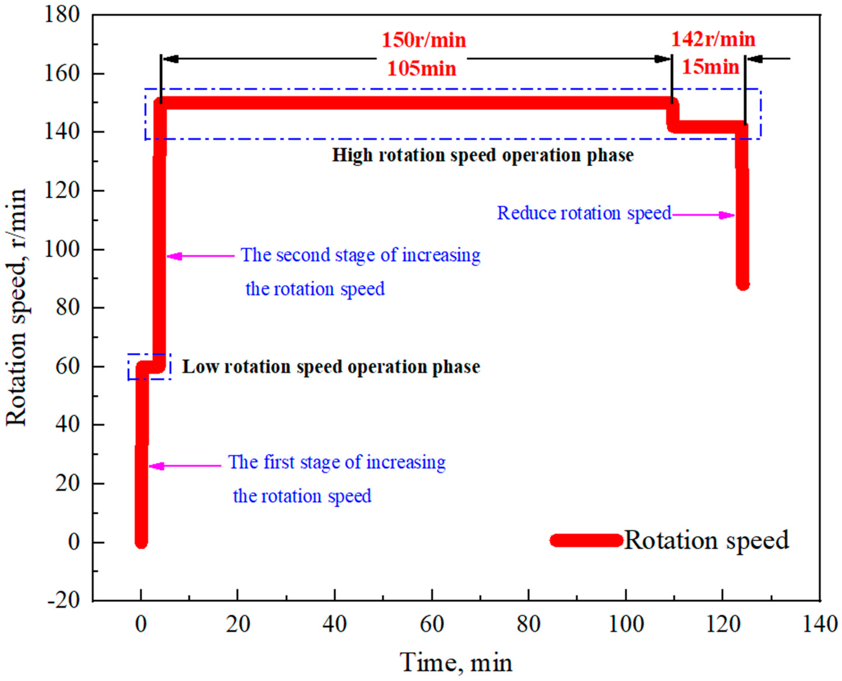
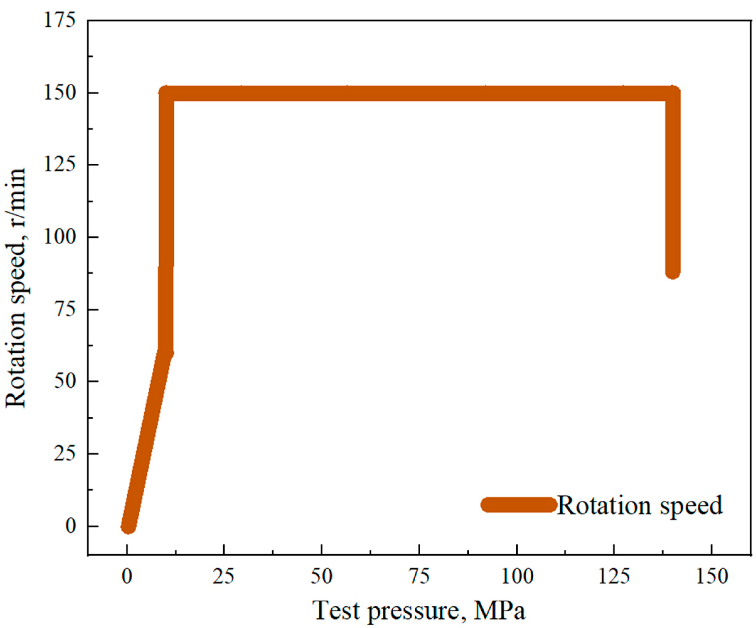
4.2.2. Results and Analysis
5. Conclusions
Author Contributions
Funding
Institutional Review Board Statement
Informed Consent Statement
Data Availability Statement
Acknowledgments
Conflicts of Interest
References
- Xie, H.P.; Konietzky, H.; Zhou, H.W. Special Issue “Deep Mining”. Rock Mech. Rock Eng. 2019, 52, 1415–1416. [Google Scholar] [CrossRef]
- Xie, H.P.; Gao, F.; Ju, Y. Research and development of rock mechanics in deep grand engineering. Chin. J. Rock Mech. Eng. 2015, 34, 2161–2178. [Google Scholar] [CrossRef]
- Yang, J.P.; Chen, L.; Gu, X.B.; Zhao, Z.Y.; Fu, C.H.; Yang, D.S.; Tian, D.Z.; Chen, Z.S.; Xie, H.P. Hollow glass microspheres/silicone rubber composite materials toward materials for high performance deep in-situ temperature-preserved coring. Pet. Sci. 2022, 19, 309–320. [Google Scholar] [CrossRef]
- He, Z.Q.; Yang, Y.; Yu, B.; Yang, J.P.; Jiang, X.B.; Tian, B.; Wang, M.; Li, X.Y.; Sun, S.Q.; Sun, H. Research on properties of hollow glass microspheres/epoxy resin composites applied in deep rock in-situ temperature-preserved coring. Pet. Sci. 2022, 19, 720–730. [Google Scholar] [CrossRef]
- Zhang, Q.G.; Fan, X.Y.; Chen, P.; Ma, T.S.; Zeng, F.T. Geomechanical behaviors of shale after water absorption considering the combined effect of anisotropy and hydration. Eng. Geol. 2020, 269, 105547. [Google Scholar] [CrossRef]
- Huang, W.; Feng, G.; He, H.L.; Chen, J.Z.; Wang, J.Q.; Zhao, Z. Development of an ultra-high pressure rotary combined dynamic seal and experimental study on its sealing performance in deep energy mining conditions. Pet. Sci. 2022, 19, 1305–1321. [Google Scholar] [CrossRef]
- Xie, H.P. Research framework and anticipated results of deep rock mechanics and mining theory. Adv. Eng. Sci. 2017, 49, 1–16. [Google Scholar] [CrossRef]
- Li, C.; Pei, J.L.; Wu, N.H.; Liu, G.K.; Huang, W.; Dai, Z.X.; Wang, R.Z.; Chen, Z.F.; Long, W.C. Rotational failure analysis of spherical-cylindrical shell pressure controllers related to gas hydrate drilling investigations. Pet. Sci. 2022, 19, 789–799. [Google Scholar] [CrossRef]
- Gao, M.Z.; Yang, B.G.; Xie, J.; Ye, S.Q.; Liu, J.J.; Liu, Y.T.; Tang, R.F.; Hao, H.C.; Wang, X.; Wen, X.Y.; et al. The mechanism of microwave rock breaking and its potential application to rock-breaking technology in drilling. Pet. Sci. 2022, 19, 1110–1124. [Google Scholar] [CrossRef]
- Wang, G.; Qin, X.J.; Han, D.Y.; Liu, Z.Y. Study on seepage and deformation characteristics of coal microstructure by 3D reconstruction of CT images at high temperatures. Int. J. Min. Sci. Technol. 2021, 31, 175–185. [Google Scholar] [CrossRef]
- Xie, H.P.; Liu, T.; Gao, M.Z.; Chen, L.; Zhou, H.W.; Ju, Y.; Gao, F.; Peng, X.B.; Li, X.J.; Peng, R.D.; et al. Research on in-situ condition preserved coring and testing systems. Pet. Sci. 2021, 18, 1840–1859. [Google Scholar] [CrossRef]
- Gao, M.Z.; Hao, H.C.; Xue, S.N.; Lu, T.; Cui, P.F.; Gao, Y.N.; Xie, J.; Yang, B.G.; Xie, H.P. Discing behavior and mechanism of cores extracted from Songke-2 hole at depths below 4500 m. Int. J. Rock Mech. Min. Sci. 2022, 149, 104976. [Google Scholar] [CrossRef]
- Gao, M.Z.; Xie, J.; Gao, Y.N.; Wang, W.Y.; Li, C.; Yang, B.G.; Liu, J.J.; Xie, H.P. Mechanical behavior of coal under different mining rates: A case study from laboratory experiments to field testing. Int. J. Min. Sci. Technol. 2021, 31, 825–841. [Google Scholar] [CrossRef]
- Zhang, Q.G.; Wang, Z.X.; Fan, X.Y.; Wei, N.; Zhao, J.; Lu, X.W.; Yao, B.W. A novel mathematical method for evaluating the wellbore deformation of a diagenetic natural gas hydrate reservoir considering the effect of natural gas hydrate decomposition. Nat. Gas Ind. B 2021, 8, 287–301. [Google Scholar] [CrossRef]
- Sun, Y.H.; Wang, Y.; Lü, X.S.; Jia, R.; Guo, W. Hole-bottom freezing method for gas hydrate sampling. J. Nat. Gas Sci. Eng. 2015, 25, 271–283. [Google Scholar] [CrossRef]
- Gao, M.Z.; Xie, J.; Guo, J.; Lu, Y.Q.; He, Z.Q.; Li, C. Fractal evolution and connectivity characteristics of mining-induced crack networks in coal masses at different depths. Geomech. Geophys. Geo-Energy Geo-Resour. 2021, 7, 9. [Google Scholar] [CrossRef]
- Hu, Y.Q.; Xie, J.; Xue, S.N.; Xu, M.; Fu, C.H.; He, H.L.; Liu, Z.Q.; Ma, S.M.; Sun, S.Q.; Wang, C.L. Research and application of thermal insulation effect of natural gas hydrate freezing corer based on the wireline-coring principle. Pet. Sci. 2022, 19, 1291–1304. [Google Scholar] [CrossRef]
- Li, J.N.; Wang, J.; Hu, Y.Q.; You, Z.X.; Xu, M.; Wang, Y.W.; Zou, Z.J.; Kang, Q.Y. Contact performance analysis of pressure controller’s sealing interface in deep in-situ pressure-preserved coring system. Pet. Sci. 2022, 19, 1334–1346. [Google Scholar] [CrossRef]
- Zhu, L.Y.; Liu, T.; Zhao, Z.Y.; Wu, Y.F.; Yang, D.S.; Shi, X.C.; Liu, Z.Q.; Lu, F.F.; Qin, P.; Gao, X.L. Deep original information preservation by applying in-situ film formation technology during coring. Pet. Sci. 2022, 19, 1322–1333. [Google Scholar] [CrossRef]
- Gao, M.Z.; Zhang, Z.L.; Yin, X.G.; Xu, C.; Liu, Q.; Chen, H.L. The location optimum and permeability-enhancing effect of a low-level shield rock roadway. Rock Mech. Rock Eng. 2018, 51, 2935–2948. [Google Scholar] [CrossRef]
- Gao, M.Z.; Zhang, J.G.; Li, S.W.; Wang, M.; Wang, Y.W.; Cui, P.F. Calculating changes in the fractal dimension of surface cracks to quantify how the dynamic loading rate affects rock failure in deep mining. J. Cent. South Univ. Technol. 2020, 27, 3013–3024. [Google Scholar] [CrossRef]
- Xu, J.J. Design of High Temperature High Pressure Simulation Test Device Program. Master’s Thesis, China University of Geosciences, Beijing, China, 2021. [Google Scholar]
- Zheng, J.H.; Zong, Y.B.; Qian, D.R.; Wang, L.; Wang, Q. Development of downhole environment simulation test equipment. Sci. Technol. Eng. 2017, 17, 21–25. [Google Scholar] [CrossRef]
- Liu, X. Design and Research on High Pressure Simulated Shaft Heating System. Master’s Thesis, Northeast Petroleum University, Daqing, China, 2018. [Google Scholar]
- Luo, Q. Design and Experimental Research of Down-Hole Tools Simulation Test Bench. Master’s Thesis, Yangtze University, Jinzhou, China, 2015. [Google Scholar]
- Kong, R.; Luan, J.F.; Wang, C.L. Stress evaluation and reliability analysis for high temperature and high-pressure vessel in the discontinuous zone. Ind. Heat. 2016, 45, 30–32. [Google Scholar] [CrossRef]
- Morandi, A.C.; Karunakaran, D.; Dixon, A.T.; Baerheim, M. Comparison of Full-Scale Measurements and Time-Domain Irregular Sea Analysis for a Large Deepwater Jack-Up. In Proceedings of the Offshore Technology Conference, Houston, TX, USA, 2–5 May 1998. [Google Scholar] [CrossRef]
- Hooker, P.R.; Brigham, W.E. Temperature and heat transfer along buried liquids pipelines. J. Pet. Technol. 1978, 30, 747–749. [Google Scholar] [CrossRef]
- Quigley, M.S.; Dzialowski, A.K.; Zamora, M. A Full-Scale Wellbore Friction Simulator. In Proceedings of the IADC/SPE Drilling Conference, Houston, TX, USA, 27 February–2 March 1990. [Google Scholar] [CrossRef]
- Kabir, C.S.; Hasan, A.R.; Jordan, D.L.; Wang, X.W. A wellbore/reservoir simulator for testing gas holes in high-temperature reservoirs. SPE Form. Eval. 1996, 11, 128–134. [Google Scholar] [CrossRef]
- Yang, L.Q. Study of the Full-Scale Drilling Simulating Test Device under the Condition of Bottom Hole Pressures. Master’s Thesis, Zhejiang University, Hangzhou, China, 2002. [Google Scholar]
- Xue, J. Overview of several foreign high temperature and high pressure simulation drilling test equipment. Foreign Geoexplor. Technol. 1995, 2, 35–36. [Google Scholar]
- Zhou, C.; Wang, X.D. Introduction of M150 simulated wellbore. Drill. Eng. 1993, 3, 16–17. [Google Scholar]
- Zhang, F.M. Development of drilling tool test system in dagang oilfield. Oil Field Equip. 2009, 384, 72–78. [Google Scholar] [CrossRef]
- Wei, L.S. Design of High Temperature and High Pressure Simulation Testing System for Instrument Development. Master’s Thesis, Southwest Petroleum University, Chengdu, China, 2016. [Google Scholar]
- Pang, D.X.; Wang, Z.M.; Pan, D. Development of high temperature and high pressure test equipment for downhole tools. Hole Test. 2017, 26, 45–48+51+77. [Google Scholar]
- Xu, D.J.; Liu, H.; Wang, Y.; Zeng, L.X.; Wang, K.; Wang, X.J. The developing and using of downhole tools experimental facility under high temperature and high pressure condition. In 2018 the National Natural Gas Annual Symposium; Natural Gas Professional Committee of Chinese Petroleum Society: Beijing, China, 2018. [Google Scholar] [CrossRef]
- Zhang, W.H.; Zhang, H.T.; Wang, W.P. Development of high temperature and high pressure vertical hole simulation test device for downhole tools. Mach. Des. Manuf. Eng. 2020, 49, 31–34. [Google Scholar]
- Ding, G.D. Design and Research on Simulation Test Shaft of High Temperature and High Pressure. Master’s Thesis, China University of Petroleum, Beijing, China, 2014. [Google Scholar]
- GB/T 34019-2017; Ultra-High Pressure Vessels. National Standards of People’s Republic of China: Beijing, China, 2017.
- Shao, G.H.; Wei, Z.C. Ultra-High Pressure Vessel; Chemical Industry Press: Beijing, China, 2002. [Google Scholar]
- Wang, J.B. Safety Analysis and Accident Prevention of High Temperature and High Pressure Testing Equipment of Logging Lools. Master’s Thesis, China University of Petroleum, Beijing, China, 2014. [Google Scholar]
- Hu, X.M.; Wang, C.L.; Cai, X.L.; Li, Q.W.; Chen, B. Development of high-temperature and high-pressure reaction kettle system. Mech. Eng. Autom. 2013, 3, 153–155. [Google Scholar] [CrossRef]
- Wang, Z.W.; Cai, R.L. Pressure Vessel Design; Chemical Industry Press: Beijing, China, 2005. [Google Scholar]
- Liu, C.; Wu, S.L.; Yang, F.; Hong, K.; Zhang, S.; Liu, X.N. Precision comparison of calculation formulas for ultra-high pressure vessel burst pressure. Press. Vessel Technol. 2019, 36, 43–49+66. [Google Scholar] [CrossRef]
- Chen, Z.W.; Li, T.; Yang, G.Y. Technical Progress in GB/T 34019—2017 Standard “Ultrahigh Pressure Vessel”. Press. Vessel Technol. 2019, 36, 46–51. [Google Scholar]


| Structural Style | Characteristic | Scope of Application | |
|---|---|---|---|
| Single-layer cylinder | Integral forging | Due to the limitation of forging conditions and high cost, it is suitable for steel with poor welding performance | The diameter of the cylinder is between 300 mm and 800 mm, and the length does not exceed 12 m |
| Roll-welded cylinder | Simple process, short cycle, high efficiency; however, it cannot be used when the cylinder diameter is too small | The diameter of the cylinder is greater than 400 mm, and the maximum thickness is 110 mm | |
| Segmentally welded cylinder | Does not need large coil equipment; low productivity | The larger the diameter is, the longer the manufacturing time | |
| Seamless tubular cylinder | The source of raw materials is convenient, the manufacturing efficiency is high, and the cycle is short | The diameter of the cylinder should not exceed 500 mm | |
| Percent Elongation after Fracture | Charpy Impact Work | Fracture Toughness | Area Reduction |
|---|---|---|---|
| ≥16% | ≥41 J | ≥120 MPa | ≥40% |
| Yield Strength, MPa | Strength of Extension, MPa | Percent Elongation after Fracture | Area Reduction | Shock Absorption Energy | Lateral Expansion, mm |
|---|---|---|---|---|---|
| ≥960 | 1070–1230 | ≥16 | ≥45 | ≥47 | ≥0.53 |
| Mark | Intensity Index | Date |
|---|---|---|
| 35CrNi3MoVR | Yield strength | ≥857 MPa |
| Strength of extension | ≥1060 MPa |
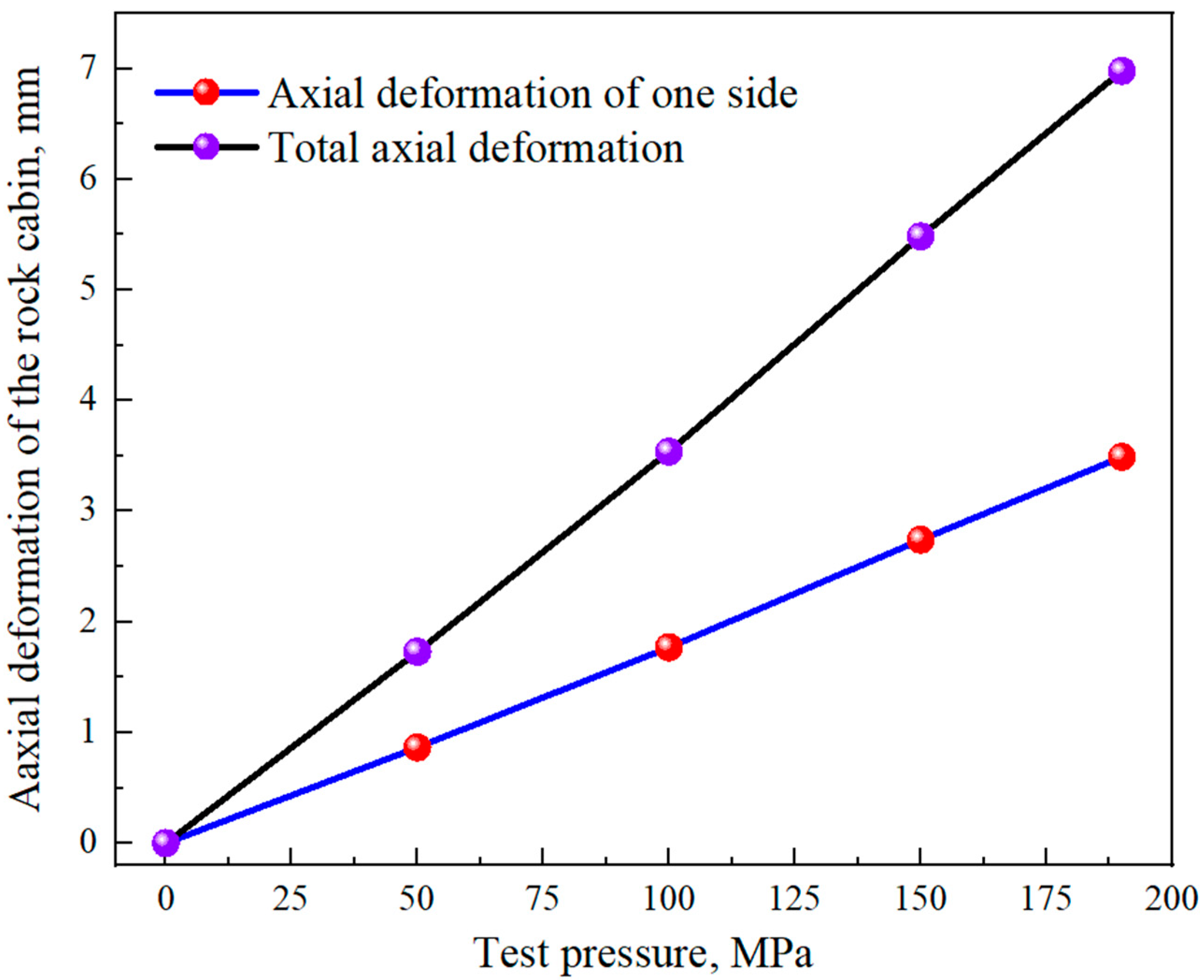
| Test Pressure, MPa | Axial Displacement Test Data, mm | Unilateral Axial Deformation, mm | Total Axial Deformation, mm |
|---|---|---|---|
| 0 | 1.000 | 0 | 0 |
| 50 | 1.865 | 0.865 | 1.730 |
| 100 | 2.769 | 1.769 | 3.538 |
| 150 | 3.742 | 2.742 | 5.484 |
| 190 | 4.490 | 3.490 | 6.980 |
| Test Pressure, MPa | Axial Displacement 2, mm | Axial Displacement 1, mm | Total Axial Deformation, mm |
|---|---|---|---|
| 0 | 0 | 0 | 0 |
| 50 | 0.285 | 0.350 | 0.635 |
| 100 | 0.567 | 0.630 | 1.197 |
| 150 | 0.873 | 0.932 | 1.805 |
| 190 | 1.115 | 1.194 | 2.309 |
Disclaimer/Publisher’s Note: The statements, opinions and data contained in all publications are solely those of the individual author(s) and contributor(s) and not of MDPI and/or the editor(s). MDPI and/or the editor(s) disclaim responsibility for any injury to people or property resulting from any ideas, methods, instructions or products referred to in the content. |
© 2023 by the authors. Licensee MDPI, Basel, Switzerland. This article is an open access article distributed under the terms and conditions of the Creative Commons Attribution (CC BY) license (https://creativecommons.org/licenses/by/4.0/).
Share and Cite
Huang, W.; Xie, H.; Li, J.; Yang, Y.; Li, C.; He, Z.; Li, Y.; Zhang, Z. Development of an In-Situ Simulation Device for Testing Deep Pressure-Preserving Coring Tools under High-Temperature and Ultrahigh-Pressure Conditions. Appl. Sci. 2023, 13, 3889. https://doi.org/10.3390/app13063889
Huang W, Xie H, Li J, Yang Y, Li C, He Z, Li Y, Zhang Z. Development of an In-Situ Simulation Device for Testing Deep Pressure-Preserving Coring Tools under High-Temperature and Ultrahigh-Pressure Conditions. Applied Sciences. 2023; 13(6):3889. https://doi.org/10.3390/app13063889
Chicago/Turabian StyleHuang, Wei, Heping Xie, Jianan Li, Yang Yang, Cong Li, Zhiqiang He, Yihang Li, and Zetian Zhang. 2023. "Development of an In-Situ Simulation Device for Testing Deep Pressure-Preserving Coring Tools under High-Temperature and Ultrahigh-Pressure Conditions" Applied Sciences 13, no. 6: 3889. https://doi.org/10.3390/app13063889
APA StyleHuang, W., Xie, H., Li, J., Yang, Y., Li, C., He, Z., Li, Y., & Zhang, Z. (2023). Development of an In-Situ Simulation Device for Testing Deep Pressure-Preserving Coring Tools under High-Temperature and Ultrahigh-Pressure Conditions. Applied Sciences, 13(6), 3889. https://doi.org/10.3390/app13063889