1. Introduction
In recent years, the number of human-made objects launched into space has continued to grow [
1,
2,
3], increasing the danger of the near-Earth debris environment and increasing the risk of in-space collisions [
4,
5,
6,
7]. Mitigation regulations [
8] and strategies [
9] have been and are continuously being proposed, and active [
10] and passive [
11,
12] debris removal and post-mission disposal technologies are under development. It is clear that the risk of debris impacts shall be considered in the development of a space mission: a collision can cause damage to spacecraft subsystems and affect their functionality [
13], up to the complete loss of the vehicle. Eventually, critical events may lead to the partial or complete fragmentation of the impacted bodies [
14].
In this context, on one hand, dedicated protections are designed to shield satellites from hypervelocity impacts; ground tests are usually employed to assess their capability to mitigate collisions [
15,
16] and to protect spacecraft components [
17,
18]. Furthermore, critical elements are usually subjected to similar tests to evaluate their survivability in the debris environment [
19]. On the other hand, it is crucial to understand the physical processes involved in spacecraft collisions through numerical simulations and ground-based experiments. Currently, spacecraft collisions and large fragmentation events are evaluated mostly with empirical or semi-empirical tools (e.g., NASA SBM [
20], FASTT [
21,
22], IMPACT [
23,
24]), as numerical simulations based on the impact physics (e.g., hydrocodes) are usually too complex and resource-consuming to investigate a wide range of collision scenarios. Ground tests of complex satellite models [
25,
26,
27] usually require large impact facilities and a large amount of worker hours for fragment collection and analysis [
28].
The Space Debris group of the University of Padova has investigated both these topics in collaboration with national and international partners; this paper presents the experimental and numerical research activities performed by the group in the last 10 years. The next section introduces the Hypervelocity Impact Facility employed for the experimental investigation, consisting of a two-stage Light-Gas Gun capable of accelerating projectiles up to 100 mg at a maximum speed of 5.5 km/s. The purposes of the experimental campaigns, which are presented in
Section 3, are (i) the evaluation of the ballistic response of satellite structures and components subjected to impacts with small debris of mm size, (ii) the development of new shields with enhanced shielding capabilities, (iii) the investigation of fragmentation processes at component and system level, and (iv) the development of smart systems for in situ small debris impact detection. The second part of this work describes the impact modelling research (
Section 4), focusing on simulations of collision scenarios involving both basic elements and full satellites (
Section 5). In particular, the collected results can be compared to those of current breakup models such as the NASA SBM, and to derive new semi-empirical formulations of the fragmentation process.
2. The Hypervelocity Impact Facility
The Center for Space Activities CISAS “G. Colombo” was founded in 1991 as an interdisciplinary structure able to host research activities performed by the different departments of the University of Padova in the field of space science and technology. Regarding space debris, the activities grew considerably in the late 1990s with the development of a unique impact facility based upon a Two-Stage Light-Gas Gun (LGG). From 2001, a complete laboratory was established for high-velocity and hypervelocity impact physics, with the development and procurement of various instruments for impact diagnostics [
29,
30,
31,
32]. The current facility can be seen in
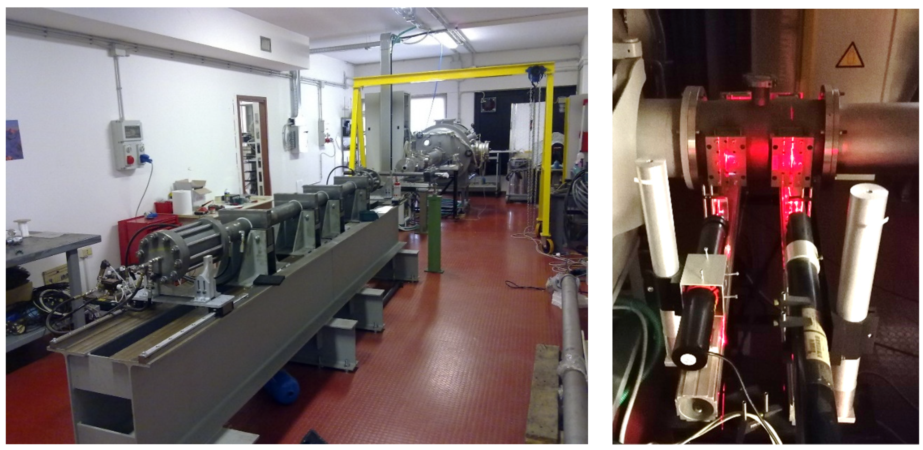
Figure 1 (left); it is capable of accelerating projectiles up to 100 mg at a maximum speed of 5.5 km/s; its main innovation is the high shot frequency, up to 10 experiments per day, achievable due to a specific setup which employs reusable components in the whole main gas gun subsystem, including the piston and the high-pressure section. The current LGG consists of (1) a first-stage reservoir, where a light gas is stored at high pressure, (2) a pneumatic piston, which is accelerated by the gas in the first stage, (3) a tube acting as a second stage in which a light gas is compressed by the piston, (4) a high-pressure section with reusable pneumatic valves to release the high-pressure gas on the back of the launch package, (5) a barrel, in which the launch package, made by the sabot and the projectile, is accelerated by the compressed gas from the second stage, (6) a flight chamber in which the projectile continues its trajectory towards the target, (7) a sabot stopping system, and (8) an impact chamber in which the projectile hits the target. The projectile velocity is measured by two laser optical barriers placed just before the impact chamber (
Figure 1, right); a high-velocity camera is placed on one side of the impact chamber and is employed to record impact videos. In addition, dedicated sensors can be added to instrument the target depending on the experimental setup (e.g., accelerometers, acoustic sensors, ballistic pendulum).
3. Experimental Activities
In this section, the most important experimental activities performed in the last decade with the Hypervelocity Impact Facility of the University of Padova are summarized. They are divided into four main branches: (i) evaluation of the ballistic response of satellite systems subjected to impacts with small debris of mm size, (ii) development of new shields with enhanced shielding capabilities, (iii) investigation of the fragmentation process at component and system level, and (iv) development of smart systems for in situ small debris impact detection.
3.1. Evaluation of the Ballistic Response of Satellite Systems
The ballistic response of structures and systems is usually investigated through hypervelocity impact tests and often through simulations to explore impact ranges not achievable in the laboratory. These studies aim to identify the projectile critical diameter (usually, in respect of the impact velocity and/or other impact parameters) which makes a structure or a system fail in the case of a collision. The ballistic response can be expressed through Ballistic Limit Equations (BLEs). In this context, the investigations performed by the Space Debris group of the University of Padova focused on the BLEs for tape tethers.
Tape Tethers
Space tethers have been proposed for a large number of applications, from futuristic space elevators to dynamic systems able to raise or lower the orbit of a satellite [
33]. In particular, electrodynamic tethers employ the interaction with the space plasma and the Earth’s magnetosphere to generate thrusts that can be used for orbital maneuvers. Among the main constraints in this application, the scientific community is worried that long and thin wires could be strongly affected by the debris environment: any small impact may result in the severing of the tether [
34]. To overcome this limitation, thin tape tethers were proposed due to their non-symmetric behavior during impacts (in addition to other positive features such as an enhanced capacity to collect plasma for electrodynamic applications). The investigation of the ballistic response of tape tethers to impacts was carried out at the University of Padova in the framework of Project 262972 (BETs) funded by the European Commission under the FP7 Space Program [
35,
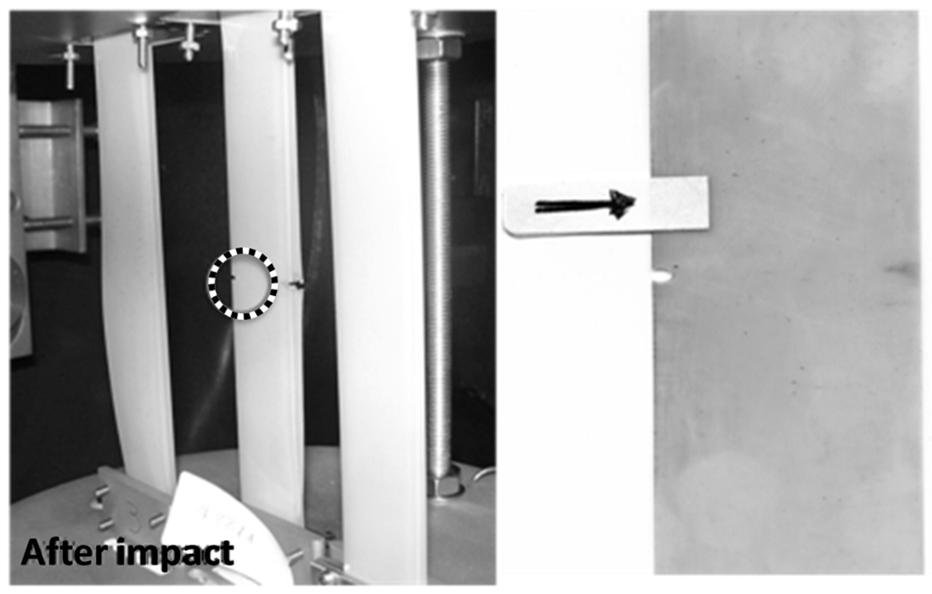
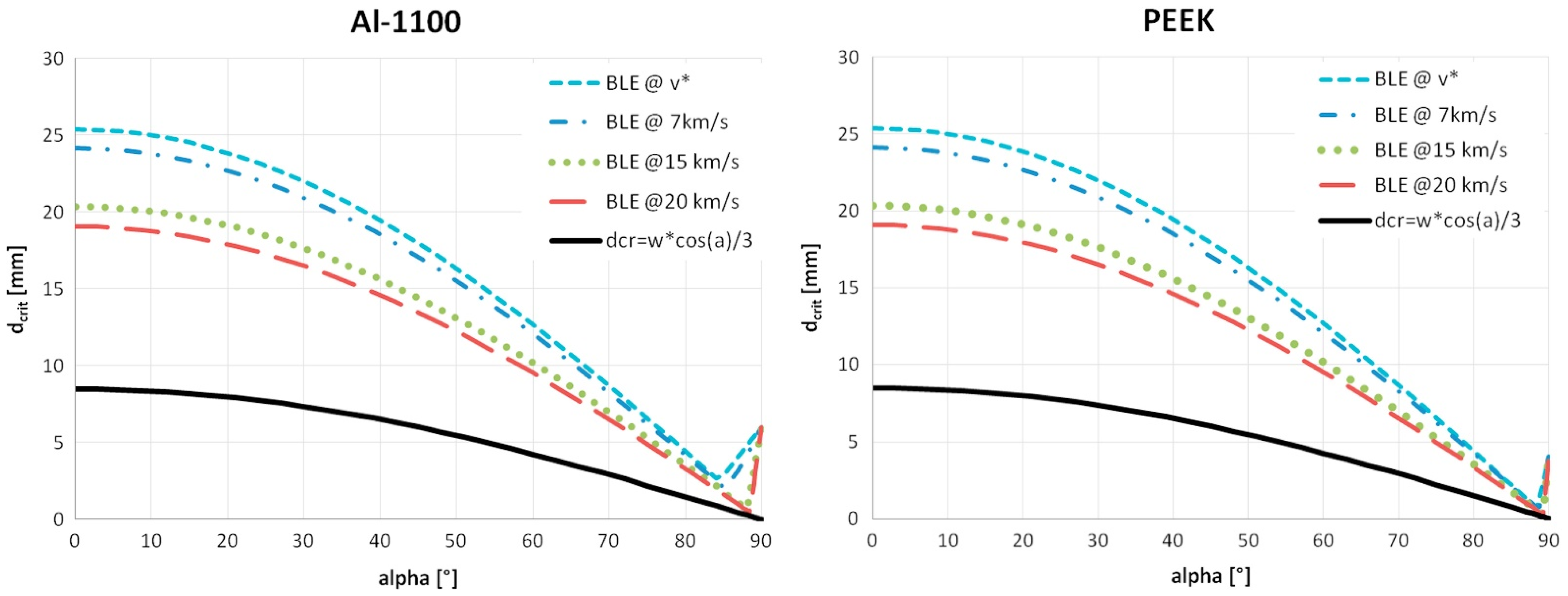
36]. In this activity, a set of 24 experiments with different projectiles diameters, velocities, and impact angles was performed on aluminum and polymeric tapes; 112 additional numerical simulations were executed with a commercial software ANSYS™ Autodyn to evaluate impact conditions outside of the LGG operational range. The experimental setup and the damage on a PEEK tape from an impact test can be seen in
Figure 2;
Figure 3, which report the ballistic limit of the tape tether in respect of the impact angle and velocity as obtained from the analysis of the test results. It is shown that there is a minimum value of debris velocity v* below which no critical damage is possible; furthermore, there is a minimum velocity-dependent value d* of debris diameter below which no critical damage is possible. This is an extremely important result, since it sets a minimum particle diameter for risk assessment and thus excludes a large part of the flux from risk computations [
35].
The advantage of employing tape tethers has become clear to the scientific community. The European Commission has funded the current projects E.T.Pack and E.T. PACK-Fly, which aim to demonstrate tether technology for satellites deorbiting at the end of their operational life [
12,
37]; both projects employ the same tape tethers investigated in the BETs study.
3.2. Advanced Shielding for Spacecraft
Among the experimental activities, test campaigns were dedicated to the investigation of the shielding capability of advanced configurations or novel materials. With respect to standard sandwich panels, currently used as structural elements with a certain shielding capability, new materials and configurations may show enhanced performances. Hypervelocity impact testing allows the determination of the ballistic limit of these new configurations, as well as the ability to fragment impacting bodies to further reduce the vulnerability of internal components to perforation.
3.2.1. Carbon-Fiber-Reinforced Panels (CFRPs)
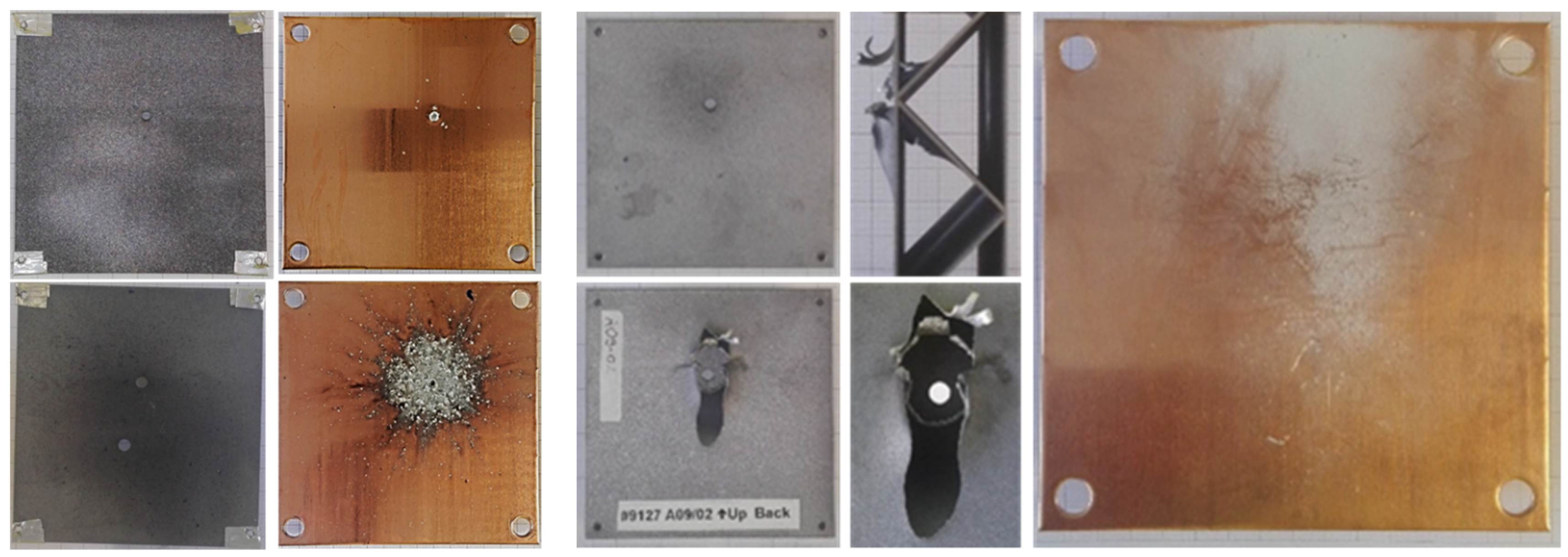
In the framework of a collaboration between CISAS and JAXA (Japan Aerospace Exploration Agency), a campaign of hypervelocity tests was performed on CFRPs (
Figure 4). In total, 45 experiments were performed on panels 2.3, 3.5, and 4.3 mm thick, with spherical projectiles with diameter from 0.8 to 2.9 mm impacting at a speed of 2–5 km/s. This campaign allowed the definition of the panels’ Ballistic Limit Equation, as well as the determination of the panels’ internal delamination during hypervelocity impacts. Further data can be found in [
38].
3.2.2. Self-Healing Advanced Panels
In the framework of the IMpact BEhavior of MUltifunctional materialS (IMBEMUS) project, supported by the CARIPARO Foundation, the mechanical behavior of multifunctional panels was studied under impact conditions. The investigation required both high-velocity impact experiments and numerical simulations, performed with ANSYS™ Autodyn. In particular, multi-layer panels composed of ionomeric polymers with self-healing properties were subjected to 14 impact experiments; the self-healing (see
Figure 5) was successful in all but one ionomer samples and the primary damage on ionomeric polymers was found to be significantly lower than that on aluminum. On the other hand, aluminum plates exhibited slightly better debris fragmentation abilities, even though the protecting performance of ionomers seemed to improve at increasing impact speed. Further data and the main experimental campaign results can be found in [
39,
40,
41].
3.2.3. 3D-Printed Shields
The H2020 ReDSHIFT (Revolutionary Design of Spacecraft through Holistic Integration of Future Technologies) project focused on the development of highly innovative and low-cost spacecraft solutions for debris protection and mitigation, including design for demise and novel manufacturing strategies and technologies [
42]. In this project, hypervelocity impact testing investigated the response of aluminum shield panels with complex core geometry produced through additive manufacturing. Both simple plates (
Figure 6, left) and multi-layer configurations (
Figure 6, right) were investigated in the experimental campaign, which included 20 shots with different projectiles at velocities in the range between 1 and 5 km/s. Results showed that the manufacturing process did not significantly influence the response of samples to impacts and that multi-layer configurations present improvements in terms of debris shielding with respect to standard honeycomb sandwich panels with equivalent areal density and thickness [
43].
3.3. Investigation of the Fragmentation Process
Investigating the physics behind orbital collisions, and in particular the production of new fragments, is important for understanding the evolution of the space debris environment. In this context, the University of Padova is studying the fragmentation process of both simple and complex targets, with particular focus on the characteristics and the distributions of the generated debris. This work, supported by the European Space Agency in the framework of a collaboration with SpaceDys [
44], included a campaign of impact tests on aluminum and CFRP simple plates and sandwich panels and a catastrophic fragmentation experiment on a Picosatellite mock-up.
3.3.1. Aluminum and CFRP Plates
The investigation of aluminum thin plates aimed to evaluate the effect of impact velocity and target thickness on fragment generation. Four tests were performed on aluminum plates of two different thicknesses (2 and 5 mm). Aluminum spherical projectiles of 2.9 mm in diameter were launched at velocities between 3.5 and 4.8 km/s. The fragments generated by the impact were collected, catalogued, and analyzed to obtain characteristic length cumulative distributions (see
Figure 7) and shape histograms [
45]. The results showed that characteristic length distributions can be modelled by a power law similar to the NASA SBM and that shape distributions are independent from target thickness and impact velocity.
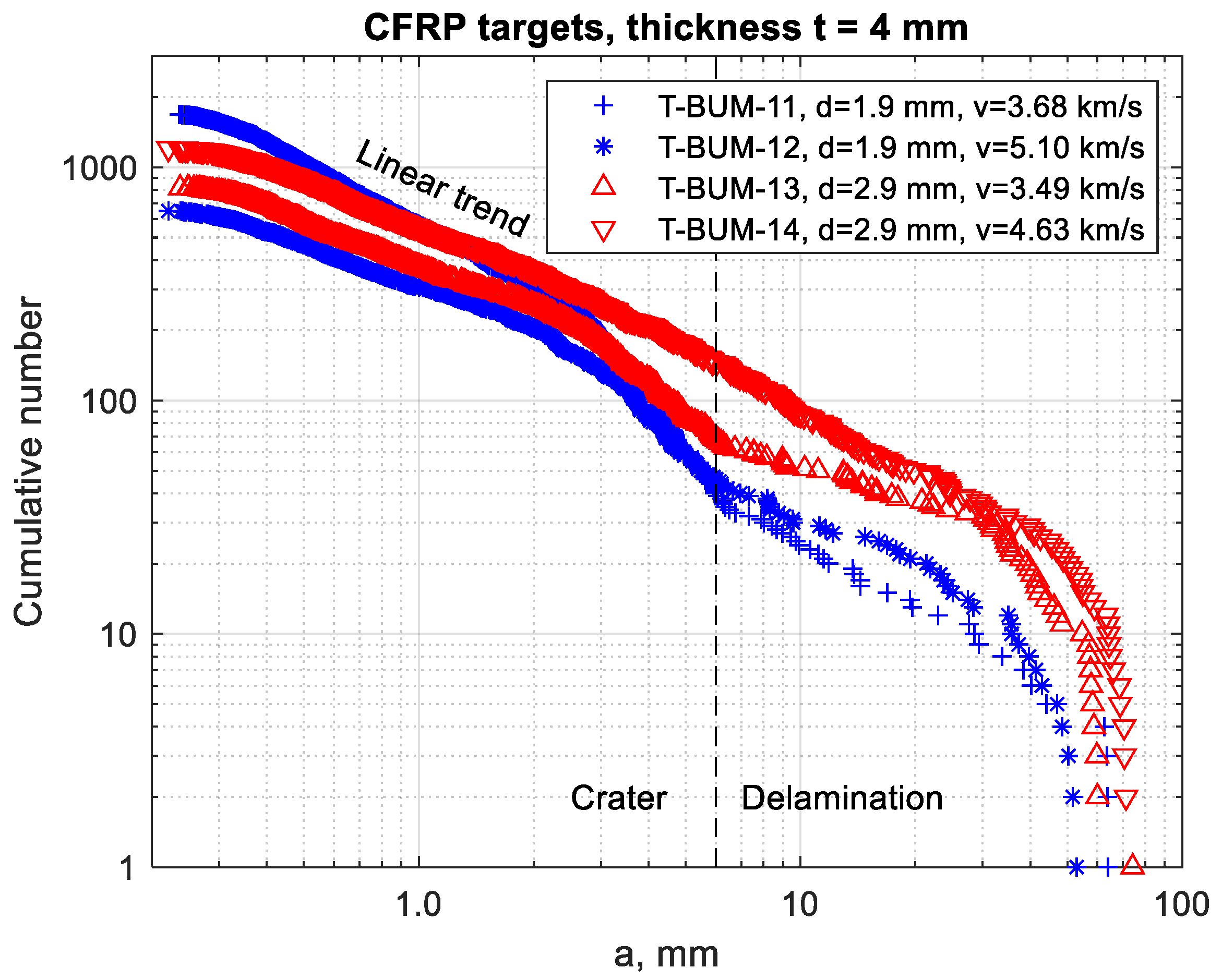
A similar campaign of four tests was performed on CFRP panels (thickness of 4 mm), with spheres of 1.9 mm and 2.9 mm impacting at velocities between 3.5 and 5.1 km/s. Again, generated fragments were collected, catalogued, and analyzed to obtain size cumulative distributions (see
Figure 8). It was observed that the distributions strongly differed from aluminum plates in terms of total number and shape, with a strong contribution, in size classes larger than 6 mm, of fragments generated by panel surface delamination. Results showed that the thickness to projectile diameter ratio and the impact velocity significantly affect the fragment size distributions; in particular, the number of fragments larger than 3 mm increases with these two parameters.
3.3.2. Sandwich Panels
The impact test campaign on sandwich panels consisted of four experiments: spheres of 2.9 mm in diameter were launched at velocities between 3.6 and 4.8 km/s. Three tests were carried out on aluminum-skin samples of two different thicknesses (1″ and 2″) and one experiment was performed on a CFRP-skin sandwich panel (0.5″ thick), to assess the effect of impact velocity, skin material, and target thickness [
46].
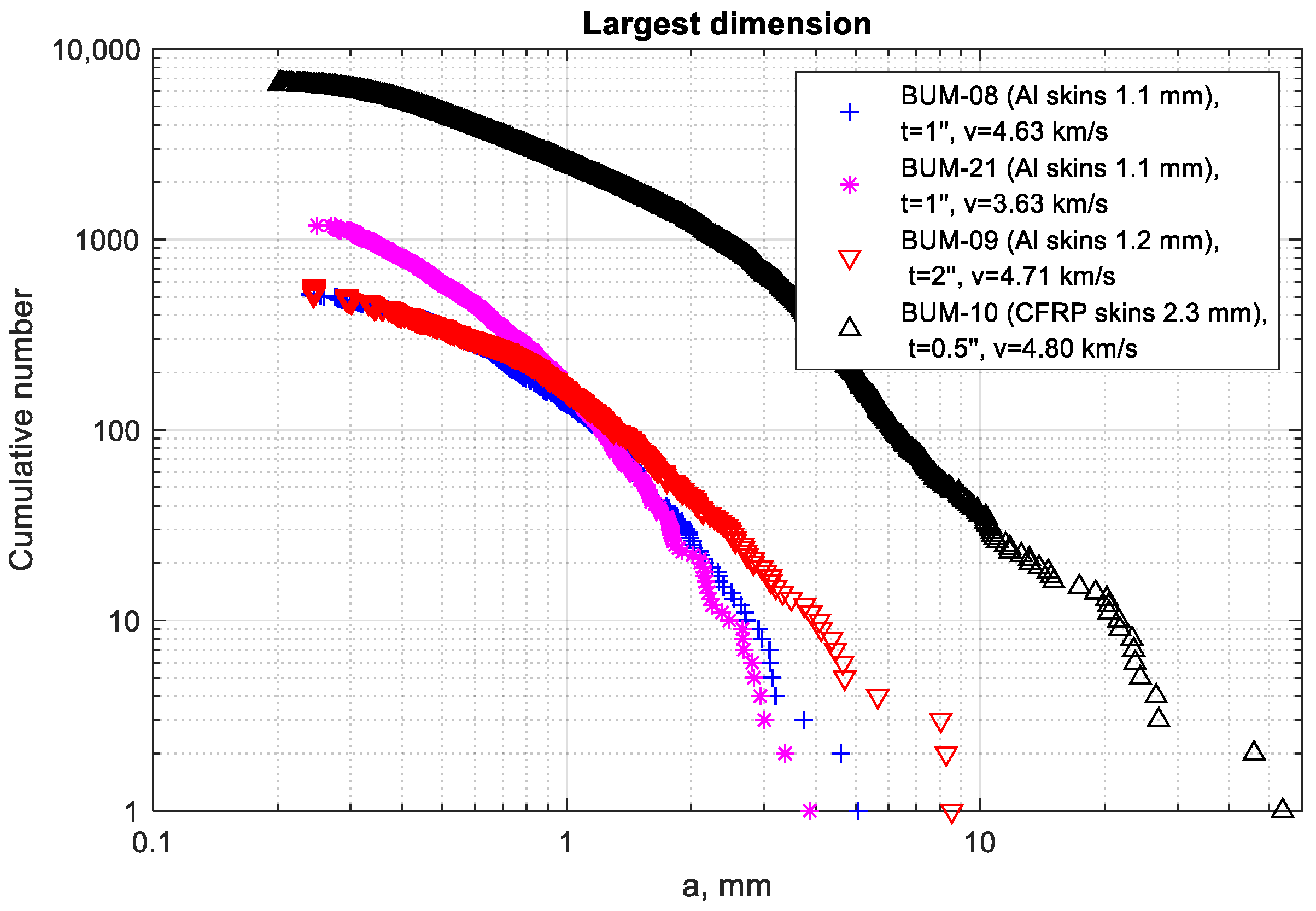
Size distributions of the generated fragments can be seen in
Figure 9. The skin material clearly affected the curves shape and the number of debris: samples with CFRP skins generated about one order of magnitude more fragments than aluminum ones. The results were compared with distributions from thin plates with comparable density (2 mm-thick aluminum plates, see
Figure 7, and a 4 mm-thick CFRP one, see
Figure 8). With respect to aluminum, the trends are comparable in terms of shape and magnitude; on the other hand, it has been observed that for CFRP, the simple plate trend is not representative of the sandwich panel, due to substantial differences in the total number of fragments and in the distribution trends.
3.3.3. Complex Mock-Up
In 2021, an impact test was performed on a 5 × 5 × 5 cm
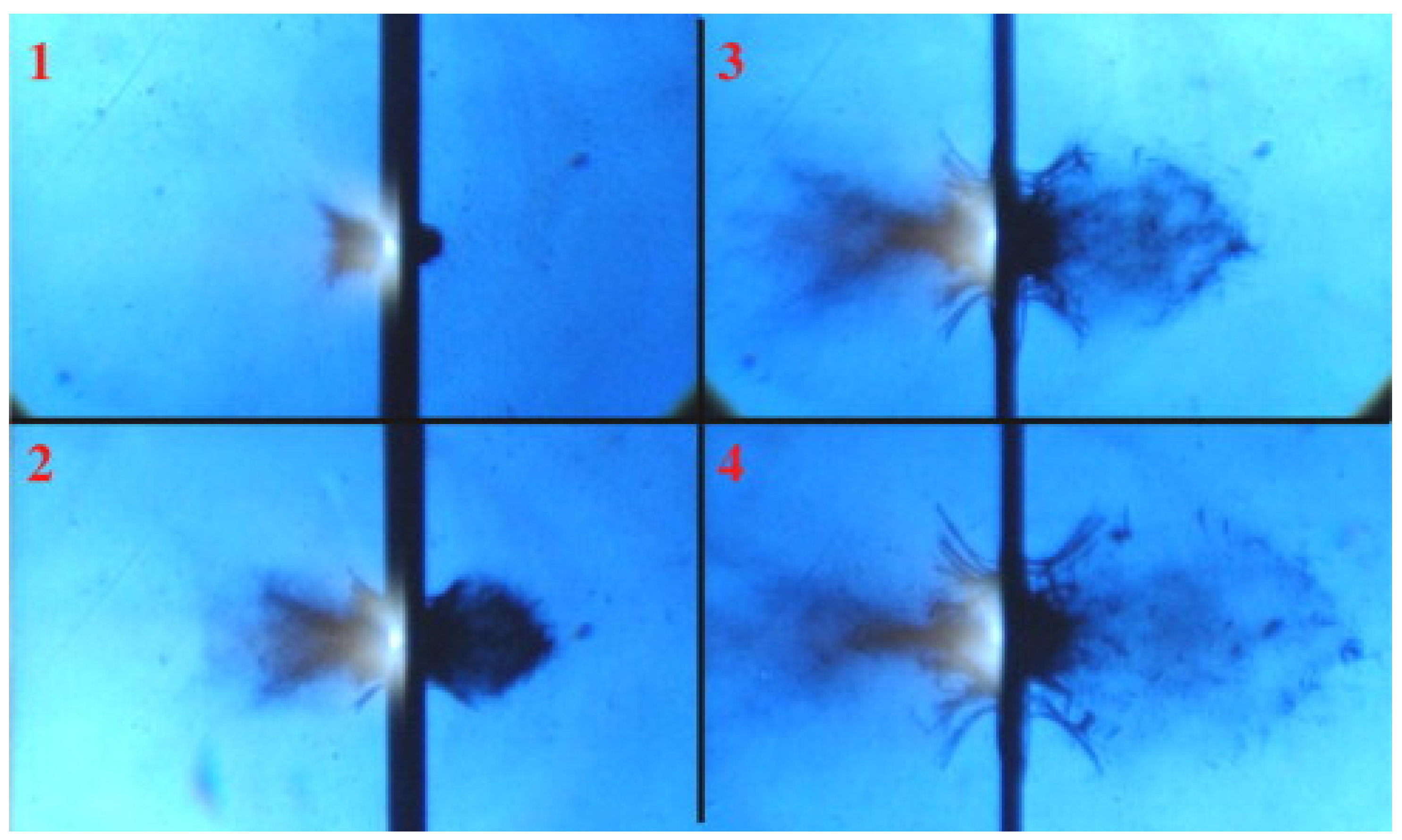
3 picosatellite mock-up with a 1.6 g nylon cylinder that hit the center of one face of the satellite at a velocity of 2.72 km/s; frames from the video of the impact can be seen in
Figure 10. The mock-up included plastic elements and consumable electronic boards to simulate the different materials employed in modern spacecraft; the fraction of different materials was about 25% metals, 20% plastics, and 55% of electronic components. The collision led to the complete fragmentation of the target; the fragments were collected, weighed, and divided into size classes [
47].
The results showed that, despite the different materials employed in the mock-up, the characteristic length distribution is in line with NASA SBM prediction, even for sizes smaller than 1 cm (see
Figure 11). However, the analysis of fragments’ area-to-mass indicated a strong influence from fragment material and a consistent deviation from the NASA SBM prediction [
47,
48].
3.4. In Situ Impact Sensors
Hypervelocity impact testing can be also employed to assess the response of in-situ impact sensors for space applications [
49,
50]. In this context, the Space Debris group of the University of Padova was involved in the CADETS (A Calorimetric Detection System for Hypervelocity Impacts) project in collaboration with the University of Oxford and the University of Malta. This activity used Thin-Film Heat-Flux Gauges (TFHFG) to measure the local increase in shield temperature following an impact event, which is correlated with the kinetic energy of the debris. The experimental campaign was performed at the University of Padova and consisted of 4 impact tests on aluminum targets instrumented with a sensor based on TFHFG technology. Results showed contributions in sensors reading from both thermal and mechanical loads, with the latter predominant. More information can be found in [
49].
4. Impact Modelling Tool
The current tools employed to simulate spacecraft catastrophic impacts and fragmentation implement empirical or semi-empirical algorithms and are based on observations of impact events and experimental data from ground tests. To date, such tools present limitations related to the novel materials employed on modern satellites (e.g., CFRP and other composites) and the evolution of manufacturing solutions; in addition, impact scenarios including glancing impacts cannot be considered in their complexity. To overcome the limitations of such solutions, the University of Padova developed the Collision Simulation Tool Solver (CSTS) in the framework of a contract awarded by the European Space Agency to CISAS and the German enterprise Etamax Space GmbH [
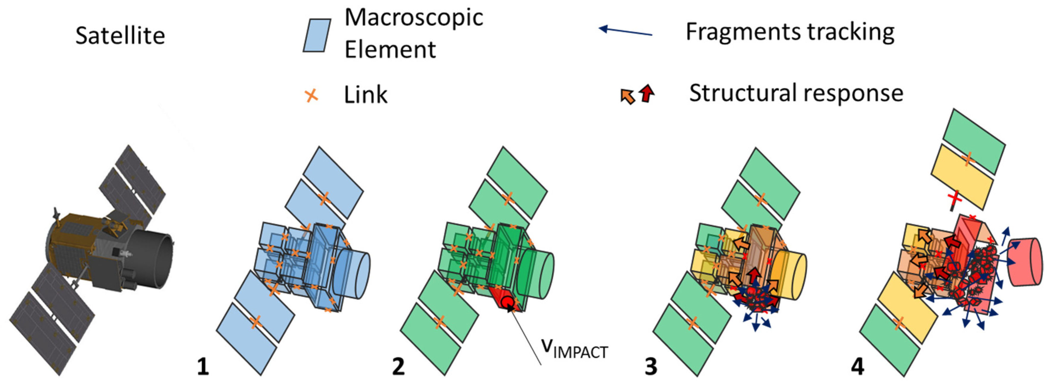
51]. In CSTS, colliding objects are modelled with a mesh of Macroscopic Elements (MEs), representing major satellite parts, connected by structural links to form a system-level net (see
Figure 12). During an impact event, the involved MEs are subjected to fragmentation, and structural damage can be transmitted through the links net; the generated fragments can affect the other MEs, creating a cascade effect representative of the object fragmentation. Based on this modelling concept, the simulator core of the CSTS is divided into three main parts: the ME Breakup Algorithm, providing fragments size, velocity, and area-to-mass distributions for a variety of spacecraft building blocks; the Structural Response Algorithm, calculating momentum transfer, energy dissipation, structural deformation, and fracture; and the Fragments Tracking Algorithm, which follows the trajectories of new debris created in the early stages of the event and detects the resulting multiple secondary impacts on other satellite parts.
This approach allows CSTS to simulate complex collision scenarios with design details included, producing statistically accurate results. In particular, CSTS allows the reduction of the complexity of the fragmentation analysis, since it is based on a set of ME fragmentation models that are easier to develop, tune, and update through testing. It was therefore possible to validate CSTS using sub-scale test results and data available in the literature.
5. Numerical Simulation Activities
CSTS was employed to investigate a set of impact scenarios and compare the results with current fragmentation models.
5.1. Impacts with a LEO Satellite: LOFT
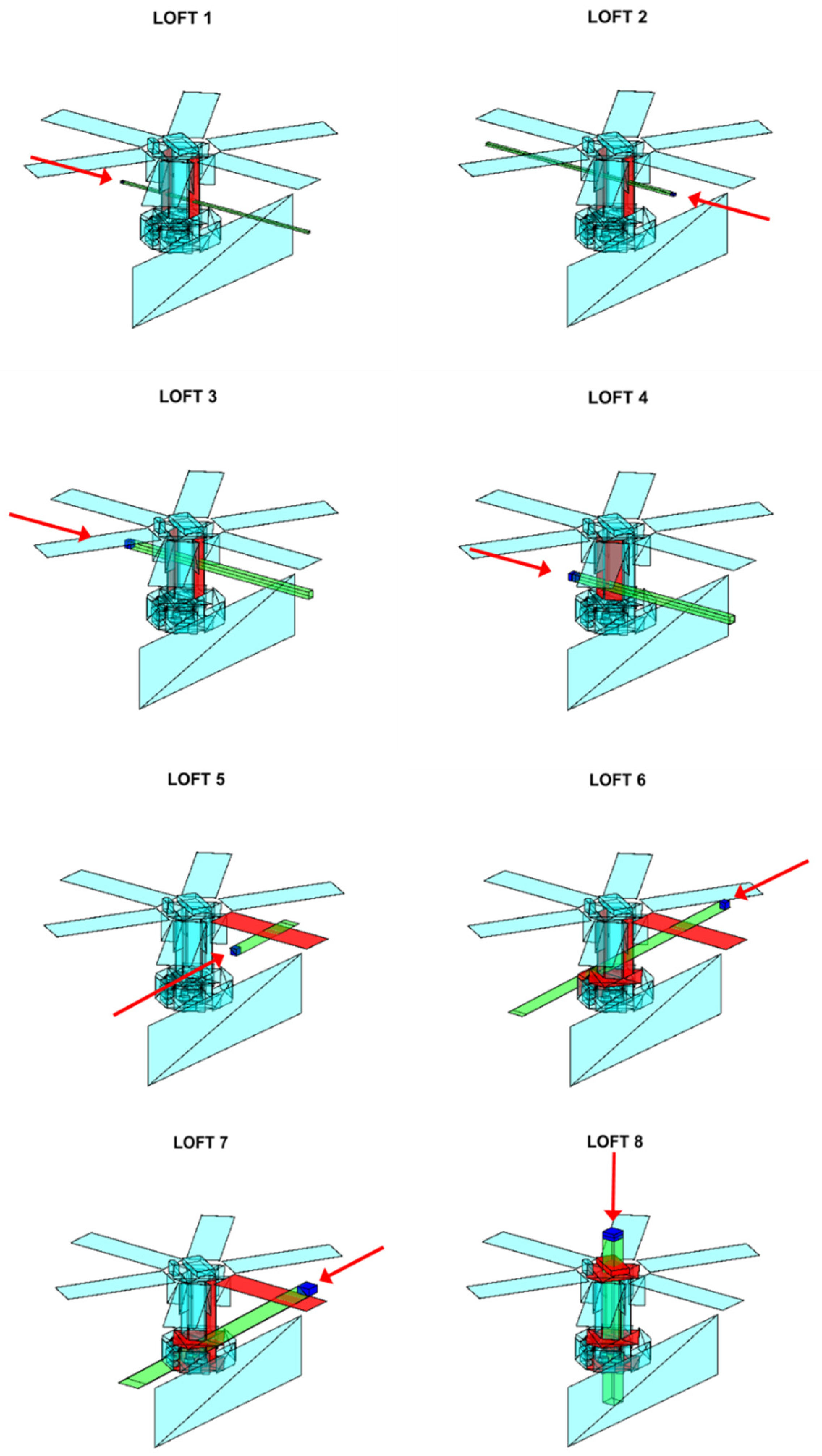
The first set of simulations focused on hypervelocity collisions involving the ESA LOFT spacecraft, with CubeSat impactors ranging from 1U to 48U and diverse collision scenarios. The study was conducted with the purpose of investigating the transition between sub-catastrophic and catastrophic collision while increasing the impactor’s kinetic energy, and the effect of impact point and encounter configuration on the collision severity. Among the eight investigated collision scenarios (see
Figure 13), the first three cases assessed LOFT fragmentation at different values of the EMR parameter. The next three cases intended to study the effect of impact point and impactor/target overlap when the EMR exceeds the accepted 40 J/g threshold for catastrophic breakup. The last two cases examined the collision of a larger body with a trajectory directed toward the denser part of the LOFT spacecraft [
52].
The simulation results indicate that the classic EMR parameter is not sufficient to model the transition between sub-catastrophic and catastrophic impact in a certain variety of collision scenarios. In fact, the same value of EMR can produce different levels of damage if the impact does not occur on the target’s center of mass or the impactor’s kinetic energy results from different combinations of impactor mass and velocity. Since these two points are not considered in the current version of the NASA SBM, it is also shown that the NASA model may overestimate the fragment distributions when impacts are not central or the ratio between impactor size and target size is small [
52].
5.2. Impacts with GEO Objects
The second set of simulated collisions involved GEO telecommunication satellites with sizes comparable to the Intelsat spacecraft family [
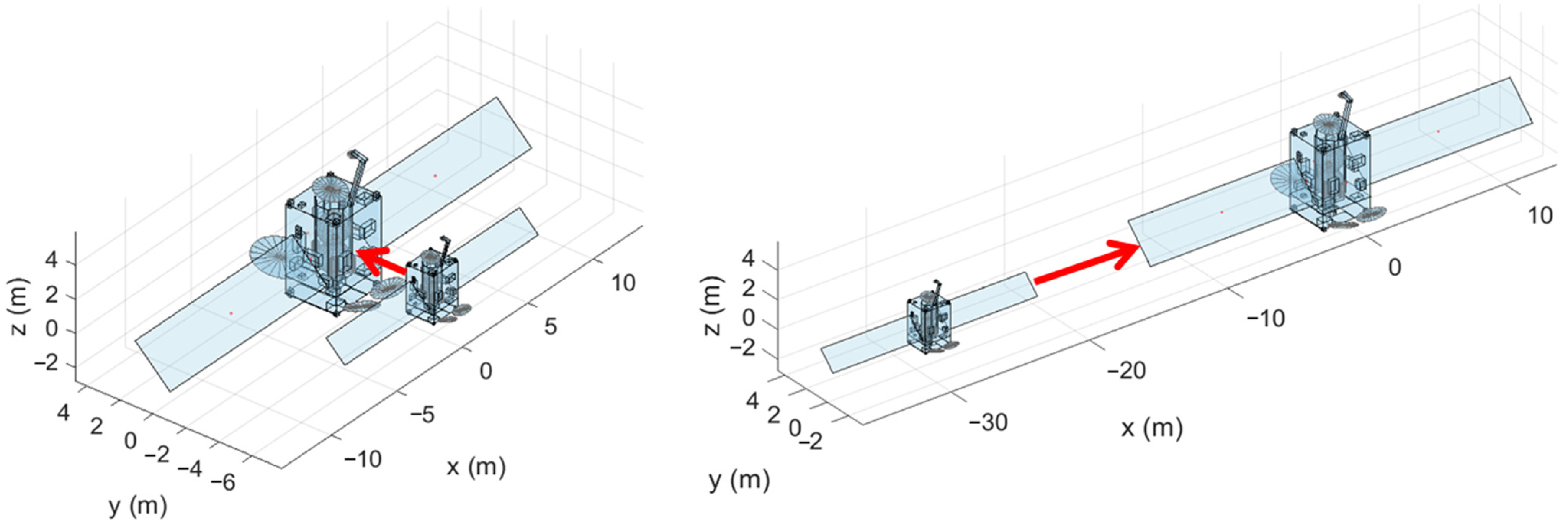
53]. The main goals of this work were to assess the transition from non-hypervelocity to hypervelocity regime, as low-velocity scenarios are of primary importance for GEO collisions, and to evaluate the influence of structural properties and impact point (when appendages interact first) to possibly dissipate impact energy and dampen the event. In the simulation campaign, both impactor and target had the same design, apart from a geometric scale factor equal to 1:0.535 (target and impactor mass were 3280 kg and 500 kg, respectively) and contained detailed elements, such as internal components, instrumentation, and antennas. The two impact conditions can be seen in
Figure 14 and consist of direct impacts on the central bodies or involving the spacecraft appendages first (solar panels). For each configuration, three impact velocities were simulated, 0.1, 1, and 10 km/s, which led to an EMR of 0.66, 66, and 6600 kJ/kg, respectively.
Among the main results collected by this work and available in [
53], it was found that the large satellite is never completely fragmented, despite the increase in the number of fragments with the impact velocity. In addition, for the 10 km/s scenarios, the impact configurations have a marginal effect on the total number of generated fragments and the number of fragments larger than 10 cm is higher in the collisions involving the appendages.
5.3. ENVISAT Collision Scenarios
The third set of simulations investigated potential collisions involving ENVISAT as target, see
Figure 15 [
54]. In this case, collision scenarios included two impactors (a 100 kg satellite and a 3-ton rocket stage) at two impact velocities (1 and 10 km/s), colliding with ENVISAT on its central body or its main appendage. Among the main results collected by this campaign of simulations, it was found that the 40 kJ/kg threshold was not representative of the transition to catastrophic impact and that the current NASA SBM significantly overestimates the number of fragments larger than 1 m. More details are reported in [
54].
5.4. Fragmentation Model Development
The simulation campaigns performed with the CSTS allowed us to conclude that there is room for improvement in the fragmentation models currently employed (e.g., NASA SBM) and, in particular, in the definition of the threshold for catastrophic impacts. A novel formulation should consider the impact geometry as well as the presence of appendages that might partially shield the involved bodies, at least for less energetic impacts. In this context, the Space Debris group proposed a new piecewise analytical fragmentation model, derived from simulation data, showing a good agreement with the fragment distribution trends [
55].
6. Conclusions
This paper presents some recent research activities conducted by the University of Padova in the framework of Space Debris. The presence of a hypervelocity impact facility, with a high shot frequency up to ten experiments per day, makes it possible to perform experimental campaigns on a wide number of targets, from advanced shields to smart structures and sensors. With respect to larger hypervelocity impact facilities, the LGG available at the University of Padova has a maximum velocity of 5.5 km/s for projectiles with a mass of up to 100 mg; investigating higher velocities requires numerical simulations, as long as their validation can be performed within the LGG operative range. The development and installation of an upgraded LGG is under evaluation; in parallel, the formal collaboration with other laboratories which complements operational parameters will allow the enhancement of the available ranges of projectiles masses and velocities. The performed experimental activities spanned from materials and structures survivability testing to the investigation of the fragmentation processes. The results from the test campaigns were in line with data collected from other institutions; in particular, fragmentation distributions can be compared with experimental results for both simple and complex targets.
In parallel, the development of the Collision Simulation Tool Solver allowed us to study complex orbital collision scenarios with large impactors and full details included. The CSTS is therefore a powerful tool for investigating catastrophic impacts and improving current spacecraft fragmentation models. The current challenges in CSTS are the extension of the number of available macroscopic elements, to include electronic boards, solar panels, and pressurized tanks; material libraries are also still limited to the most common materials employed in the space sector.
To overcome these limitations, current experimental activities focus on material fragmentation, in the framework of commercial contracts with enterprises and institutions; numerical investigations are similarly dedicated to updating the CSTS breakup models and to upgrading the catastrophic impact threshold formulation.
Author Contributions
Conceptualization, L.O., data curation, C.G. and S.L.; writing—original draft preparation, L.O. and S.L.; writing—review and editing, C.G. and A.F.; supervision, A.F.; project administration. All authors have read and agreed to the published version of the manuscript.
Funding
The IMBEMUS project was supported by the CARIPARO foundation. Results presented in
Section 3.2.3 were funded through the European Commission Horizon 2020, Framework Programme for Research and Innovation (2014–2020), under the ReDSHIFT project (grant agreement no. 687500). The CADETS project was partially funded by the Malta Council for Science and Technology. The CSTS development and the fragmentation tests were supported by the European Space Agency through contracts No. 4000119143/16/NL/BJ/zk, “Numerical simulations for spacecraft catastrophic disruption analysis”, and No. 4000133656/20/D/SR, “Exploiting numerical modelling for the characterisation of collision break-ups”. Part of this work is supported by the Italian Space Agency, in the framework of the ASI-INAF Agreement “Supporto alle attivita’ lADC e validazione pre-operativa per SST (N. 2020-6-HH.0)”.
Data Availability Statement
Not applicable.
Conflicts of Interest
The authors declare no conflict of interest.
Abbreviations
| BETs | Bare Electrodynamic Tethers |
| BLE | Ballistic Limit Equation |
| CADETS | A Calorimetric Detection System for Hypervelocity Impacts |
| CFRP | Carbon-Fiber-Reinforced Panels |
| CISAS | Center for Space Activities “G. Colombo” |
| CSTS | Collision Simulation Tool Solver |
| ENVISAT | ENVInronmental SATellite |
| EMR | Energy-to-Mass Ratio |
| ESA | European Space Agency |
| E.T.Pack | Electrodynamic Tether technology for PAssive Consumable-less deorbit Kit |
| FASTT | Fragmentation Algorithms for Strategic and Theater Targets |
| GEO | Geosynchronous Equatorial Orbit |
| IMBEMUS | IMpact BEhavior of MUltifunctional materialS |
| JAXA | Japan Aerospace Exploration Agency |
| LEO | Low Earth Orbit |
| LGG | Light-Gas Gun |
| LOFT | Large Observatory For X-ray Timing |
| ME | Macroscopic Element |
| NASA | National Aeronautics and Space Administration |
| PEEK | PolyEther Ether Ketone |
| ReDSHIFT | Revolutionary Design of Spacecraft through Holistic Integration of Future Technologies |
| SBM | Standard Breakup Model |
| TFHFG | Thin-Film Heat-Flux Gauges |
References
- Karacalioglu, A.G.; Jan, S. The impact of new trends in satellite launches on the orbital debris environment. In Proceedings of the IAASS Conference Safety First, Safety for All, Melbourne, FL, USA, 18–20 May 2016. No. ARC-E-DAA-TN31699. [Google Scholar]
- Olivieri, L.; Francesconi, A. Large constellations assessment and optimization in LEO space debris environment. Adv. Space Res. 2020, 65, 351–363. [Google Scholar] [CrossRef]
- Lewis, H.; Radtke, J.; Rossi, A.; Beck, J.; Oswald, M.; Anderson, P.; Bastida Virgili, B.; Krag, H. Sensitivity of the space debris environment to large constellations and small satellites. J. Br. Interplanet. Soc. 2017, 70, 105–117. [Google Scholar]
- Kessler, D.J.; Cour-Palais, B.G. Collision frequency of artificial satellites: The creation of a debris belt. J. Geophys. Res. Space Phys. 1978, 83, 2637–2646. [Google Scholar] [CrossRef]
- Kessler, D.J.; Johnson, N.L.; Liou, J.C.; Matney, M. The Kessler syndrome: Implications to future space operations. Adv. Astronaut. Sci. 2010, 137, 2010. [Google Scholar]
- Anselmo, L.; Rossi, A.; Pardini, C. Updated results on the long-term evolution of the space debris environment. Adv. Space Res. 1999, 23, 201–211. [Google Scholar] [CrossRef]
- McKnight, D.; Di Pentino, F.; Knowles, S. Massive Collisions In LEO—A Catalyst To Initiate ADR. In Proceedings of the 65th International Astronautical Congress, Toronto, ON, Canada, 3 October–19 September 2014. [Google Scholar]
- Yakovlev, M. The “IADC Space Debris Mitigation Guidelines” and supporting documents. In Proceedings of the 4th European Conference on Space Debris, Darmstadt, Germany, 18–20 April 2005; ESA Publications Division: Noordwijk, The Netherlands, 2005; Volume 587, pp. 591–597. [Google Scholar]
- Mark, C.P.; Surekha, K. Review of active space debris removal methods. Space Policy 2019, 47, 194–206. [Google Scholar] [CrossRef]
- Tadini, P.; Tancredi, U.; Grassi, M.; Anselmo, L.; Pardini, C.; Francesconi, A.; Branz, F.; Maggi, F.; Lavagna, M.; DeLuca, L.; et al. Active debris multi-removal mission concept based on hybrid propulsion. Acta Astronaut. 2014, 103, 26–35. [Google Scholar] [CrossRef]
- Colombo, C.; Rossi, A.; Dalla Vedova, F.; Francesconi, A.; Bombardelli, C.; Trisolini, M.; Gonzalo, J.L.; Di Lizia, P.; Giacomuzzo, C.; Khan, S.B.; et al. Effects of passive de-orbiting through drag and solar sails and electrodynamic tethers on the space debris environment. In Proceedings of the 69th International Astronautical Congress (IAC 2018), Bermen, Germany, 1–5 October 2018; IAF: Chelsea, QC, Canada, 2018. [Google Scholar]
- Olivieri, L.; Valmorbida, A.; Sarego, G.; Lungavia, E.; Vertuani, D.; Lorenzini, E.C. Test of tethered deorbiting of space debris. Adv. Astronaut. Sci. Technol. 2020, 3, 115–124. [Google Scholar] [CrossRef]
- Krag, H.; Serrano, M.; Braun, V.; Kuchynka, P.; Catania, M.; Siminski, J.; Schimmerohn, M.; Marc, X.; Kuijper, D.; Shurmer, I.; et al. A 1 cm space debris impact onto the sentinel-1a solar array. Acta Astronaut. 2017, 137, 434–443. [Google Scholar] [CrossRef]
- Kelso, T.S. Analysis of the Iridium 33 Cosmos 2251 Collision; NTRA: Washington, DC, USA, 2009.
- Christiansen, E.L. Design and performance equations for advanced meteoroid and debris shields. Int. J. Impact Eng. 1993, 14, 145–156. [Google Scholar] [CrossRef]
- Ryan, S.; Schaefer, F.; Destefanis, R.; Lambert, M. A ballistic limit equation for hypervelocity impacts on composite honeycomb sandwich panel satellite structures. Adv. Space Res. 2008, 41, 1152–1166. [Google Scholar] [CrossRef]
- Francesconi, A.; Giacomuzzo, C.; Feltrin, F.; Antonello, A.; Savioli, L. An engineering model to describe fragments clouds propagating inside spacecraft in consequence of space debris impact on sandwich panel structures. Acta Astronaut. 2015, 116, 222–228. [Google Scholar] [CrossRef]
- Schäfer, F.K.; Ryan, S.; Lambert, M.; Putzar, R. Ballistic limit equation for equipment placed behind satellite structure walls. Int. J. Impact Eng. 2008, 35, 1784–1791. [Google Scholar] [CrossRef]
- Schonberg, W.P.; Martin Ratliff, J. Hypervelocity impact of a pressurized vessel: Comparison of ballistic limit equation predictions with test data and rupture limit equation development. Acta Astronaut. 2015, 115, 400–406. [Google Scholar] [CrossRef]
- Johnson, N.L.; Krisko, P.H.; Liou, J.-C.; Anz-Meador, P.D. NASA’s new breakup model of EVOLVE 4.0. Adv. Space Res. 2001, 28, 1377–1384. [Google Scholar] [CrossRef]
- McKnight, D.; Maher, R.; Nagl, L. Fragmentation Algorithms for Strategic and Theater Targets (FASTT) Empirical Breakup Model, Ver 3.0. Int. J. Impact Eng. 1994, 17, 547–558. [Google Scholar] [CrossRef]
- McKnight, D.; Maher, R.; Nagl, L. Refined algorithms for structural breakup due to hypervelocity impact. Int. J. Impact Eng. 1995, 17, 547–558. [Google Scholar] [CrossRef]
- Sorge, M.E. Satellite fragmentation modeling with IMPACT. In Proceedings of the AIAA/AAS Astrodynamics Specialist Conference and Exhibit, Honolulu, HI, USA, 18–21 August 2008. [Google Scholar]
- Sorge, M.E.; Mains, D.L. IMPACT fragmentation model developments. Acta Astronaut. 2016, 126, 40–46. [Google Scholar] [CrossRef]
- Murray, J.; Cowarding, J.; Liou, J.-C.; Sorge, M.; Fitz-Coy, N.; Huynh, T. Analysis of the DebriSat fragments and comparison to the NASA standard satellite breakup model. In Proceedings of the International Orbital Debris Conference (IOC), Sugar Land, TX, USA, 4–7 December 2019. No. JSC-E-DAA-TN73918. [Google Scholar]
- Hanada, T.; Liou, J.C.; Nakajima, T.; Stansbery, E. Outcome of recent satellite impact experiments. Adv. Space Res. 2009, 44, 558–567. [Google Scholar] [CrossRef]
- Abdulhamid, H.; Bouat, D.; Colle, A.; Lafite, J.; Limido, J.; Midani, I.; Omaly, P. On-ground HVI on a nanosatellite. impact test, fragments recovery and characterization, impact simulations. In Proceedings of the 8th ESA Space Debris Conference, Darmstadt, Germany, 20 April 2021. [Google Scholar]
- Rivero, M.; Shiotani, B.; Carrasquilla, M.; Fitz-Coy, N.; Liou, J.C.; Sorge, M.; Huynh, T.; Opiela, J.; Krisko, P.; Cowardin, H. DebriSat fragment characterization system and processing status. In Proceedings of the International Astronautical Congress, Guadalajara, Mexico, 26–30 September 2016. No. JSC-CN-37403-1. [Google Scholar]
- Angrilli, F.; Pavarin, D.; De Cecco, M.; Francesconi, A. Impact facility based upon high frequency two-stage light-gas gun. Acta Astronaut. 2003, 53, 185–189. [Google Scholar] [CrossRef]
- Pavarin, D.; Francesconi, A. Improvement of the CISAS high-shot-frequency light-gas gun. Int. J. Impact Eng. 2003, 29, 549–562. [Google Scholar] [CrossRef]
- Pavarin, D.; Francesconi, A.; Angrilli, F. A system to damp the free piston oscillations in a two-stage light-gas gun used for hypervelocity impact experiments. Rev. Sci. Instrum. 2004, 75, 245–252. [Google Scholar] [CrossRef]
- Francesconi, A.; Pavarin, D.; Bettella, A.; Angrilli, F. A special design condition to increase the performance of two-stage light-gas guns. Int. J. Impact Eng. 2008, 35, 1510–1515. [Google Scholar] [CrossRef]
- Cosmo, M.L.; Enrico, C.L. Tethers in Space Handbook; No. NASA/CR-97-206807; Open Library: Washington, DC, USA; Springfield, VA, USA, 1997. [Google Scholar]
- Anselmo, L.; Carmen, P. The survivability of space tether systems in orbit around the earth. Acta Astronaut. 2005, 56, 391–396. [Google Scholar] [CrossRef]
- Francesconi, A.; Giacomuzzo, C.; Bettiol, L.; Lorenzini, E. A new Ballistic Limit Equation for thin tape tethers. Acta Astronaut. 2016, 129, 325–334. [Google Scholar] [CrossRef]
- Khan, S.B.; Francesconi, A.; Giacomuzzo, C.; Lorenzini, E. Survivability to orbital debris of tape tethers for end-of-life spacecraft de-orbiting. Aerosp. Sci. Technol. 2016, 52, 167–172. [Google Scholar] [CrossRef]
- Valmorbida, A.; Olivieri, L.; Brunello, A.; Sarego, G.; Sánchez-Arriaga, G.; Lorenzini, E. Validation of enabling technologies for deorbiting devices based on electrodynamic tethers. Acta Astronaut. 2022, 198, 707–719. [Google Scholar] [CrossRef]
- Francesconi, A.; Giacomuzzo, C.; Kibe, S.; Nagao, Y.; Higashide, M. Effects of high-speed impacts on CFRP plates for space applications. Adv. Space Res. 2012, 50, 539–548. [Google Scholar] [CrossRef]
- Francesconi, A.; Giacomuzzo, C.; Grande, A.; Mudric, T.; Zaccariotto, M.; Etemadi, E.; Di Landro, L.; Galvanetto, U. Comparison of self-healing ionomer to aluminium-alloy bumpers for protecting spacecraft equipment from space debris impacts. Adv. Space Res. 2013, 51, 930–940. [Google Scholar] [CrossRef]
- Grande, A.M.; Coppi, S.; Di Landro, L.; Sala, G.; Giacomuzzo, C.; Francesconi, A.; Rahman, M.A. An experimental study of the self-healing behavior of ionomeric systems under ballistic impact tests. In Behavior and Mechanics of Multifunctional Materials and Composites 2012; SPIE: Bellingham, WA, USA, 2012; Volume 8342. [Google Scholar]
- Mudric, T.; Giacomuzzo, C.; Francesconi, A.; Galvanetto, U. Experimental investigation of the ballistic response of composite panels coupled with a self-healing polymeric layer. J. Aerosp. Eng. 2016, 29, 04016047. [Google Scholar] [CrossRef]
- Rossi, A.; Alessi, E.M.; Schettino, G.; Beck, J.; Holbrough, I.; Schleutker, T.; Letterio, F.; Vicario de Miguel, G.; Becedas Rodriguez, J.; Dalla Vedova, F.; et al. The H2020 ReDSHIFT project: A successful European effort towards space debris mitigation. In Proceedings of the 70th International Astronautical Congress (IAC 2019), Washington, DC, USA, 21–25 October 2019. [Google Scholar]
- Olivieri, L.; Giacomuzzo, C.; Francesconi, A.; Stokes, H.; Rossi, A. Experimental characterization of multi-layer 3D-printed shields for microsatellites. J. Space Saf. Eng. 2020, 7, 125–136. [Google Scholar] [CrossRef]
- Dimare, L.; Francesconi, A.; Giacomuzzo, C.; Cicalò, S.; Rossi, A.; Olivieri, L.; Sarego, G.; Guerra, F.; Lemmens, S.; Braun, V. Advances in the characterisation of collision break-ups by means of numerical modelling. In Proceedings of the 72th International Astronautical Congress (IAC 2021), Dubai, United Arab Emirates, 25–29 October 2021. [Google Scholar]
- Olivieri, L.; Cinzia, G.; Alessandro, F. Experimental fragments distributions for thin aluminium plates subjected to hypervelocity impacts. Int. J. Impact Eng. 2022, 170, 104351. [Google Scholar] [CrossRef]
- Olivieri, L.; Cinzia, G.; Alessandro, F. Impact fragments from honeycomb sandwich panels. In Proceedings of the 73rd International Astronautical Congress, Paris, France, 18–22 September 2022. [Google Scholar]
- Olivieri, L.; Smocovich, P.A.; Giacomuzzo, C.; Francesconi, A. Characterization of the fragments generated by a Picosatellite impact experiment. Int. J. Impact Eng. 2022, 168, 104313. [Google Scholar] [CrossRef]
- Olivieri, L.; Cinzia, G.; Alessandro, F. Analysis of fragments larger than 2 mm generated by a picosatellite fragmentation experiment. Acta Astronaut. 2023, 204, 418–424. [Google Scholar] [CrossRef]
- Barilaro, L.; Falsetti, C.; Olivieri, L.; Giacomuzzo, C.; Francesconi, A.; Beard, P.; Camilleri, R. A conceptual study to characterize properties of space debris from hypervelocity impacts through Thin Film Heat Flux Gauges. In Proceedings of the IEEE MetroAerospace, Naples, Italy, 23–25 June 2021. [Google Scholar]
- Colombo, C.; Trisolini, M.; Scala, F.; Brenna, M.P.; Gonzalo Gòmez, J.L.; Antonetti, S.; Di Tolle, F.; Redaelli, R.; Lisi, F.; Marrocchi, L.; et al. Cube mission: The environmental CubeSat. In Proceedings of the 8th European Conference on Space Debris, ESA/ESOC, Darmstadt, Germany, 20 April 2021; ESA: Paris, France, 2021. [Google Scholar]
- Francesconi, A.; Giacomuzzo, C.; Olivieri, L.; Sarego, G.; Duzzi, M.; Feltrin, F.; Valmorbida, A.; Bunte, K.D.; Deshmukh, M.; Farahvashi, E.; et al. CST: A new semi-empirical tool for simulating spacecraft collisions in orbit. Acta Astronaut. 2019, 160, 195–205. [Google Scholar] [CrossRef]
- Francesconi, A. Examination of satellite collision scenarios spanning low to hypervelocity encounters using semi-empirical models. In Proceedings of the 70th International Astronautical Congress (IAC), Washington, DC, USA, 21–25 October 2019. [Google Scholar]
- Francesconi, A.; Giacomuzzo, C.; Olivieri, L.; Sarego, G.; Valmorbida, A.; Duzzi, M.; Bunte, K.D.; Farahvashi, E.; Cardone, T.; de Wilde, D. Numerical simulations of hypervelocity collisions scenarios against a large satellite. Int. J. Impact Eng. 2022, 162, 104130. [Google Scholar] [CrossRef]
- Olivieri, L.; Giacomuzzo, C.; Duran-Jimenez, C.; Francesconi, A.; Colombo, C. Fragments Distribution Prediction for ENVISAT Catastrophic Fragmentation. In Proceedings of the 8th European Conference on Space Debris, ESA/ESOC, Darmstadt, Germany, 20 April 2021; ESA: Paris, France, 2021. [Google Scholar]
- Olivieri, L.; Giacomuzzo, C.; Francesconi, A. Simulations of satellites mock-up fragmentation. Acta Astronaut. 2023, 206, 233–242. [Google Scholar] [CrossRef]
| Disclaimer/Publisher’s Note: The statements, opinions and data contained in all publications are solely those of the individual author(s) and contributor(s) and not of MDPI and/or the editor(s). MDPI and/or the editor(s) disclaim responsibility for any injury to people or property resulting from any ideas, methods, instructions or products referred to in the content. |
© 2023 by the authors. Licensee MDPI, Basel, Switzerland. This article is an open access article distributed under the terms and conditions of the Creative Commons Attribution (CC BY) license (https://creativecommons.org/licenses/by/4.0/).
