Article

Model Experimental Study on De-Icing Method of Bridge Pylon Beam Based on Electric Heating

1
School of Civil Engineering and Environment, Hubei University of Technology, Wuhan 430068, China
2
Xiangyang Industrial Institute, Hubei University of Technology, Xiangyang 441100, China
*
Author to whom correspondence should be addressed.
Appl. Sci. 2023, 13(6), 3793; https://doi.org/10.3390/app13063793
Submission received: 12 February 2023 / Revised: 6 March 2023 / Accepted: 14 March 2023 / Published: 16 March 2023

Abstract

:
The icing of bridge pylon crossbeams is a problem that could pose a serious threat to traffic during a cold winter. However, little research has been carried out on the problem and few corresponding countermeasures have been provided. This paper aims to propose a novel heating system, and to study the feasibility of beam de-icing and the related de-icing strategies so as to provide a reference scheme for the practical application of beam de-icing. A number of icing and de-icing tests were carried out on a scale model of Wuhan Yangtze River Second Bridge in the cold chamber. The de-icing effects of the beam in different environments and different de-icing methods were compared, and the recommended pre-heating time, applicable environment range, and heating method were given. The results of the model experiments show that pre-heating the heating system can prevent the surface of the beam from freezing and that the anti-icing method is more suitable for beam de-icing than the passive de-icing method. When the pre-heating time exceeds 7 min, the entire anti-icing process can be ice-free. When the wind velocity exceeds 5 m/s, it is safer to shut down the heating system, and using the passive de-icing method at the end of the icing can also eliminate the hidden danger of beam icing.

1. Introduction

During the cold winter months, a bridge’s upper elements, such as diagonal cables and bridge pylon crossbeams, ice and form large amounts of long icicles due to rainfall and snowfall. With the rising temperature, the dangling icicles can easily fall off and crash onto the bridge deck, injuring passing vehicles and pedestrians. In 2018, a similar ice-fall problem occurred on the Erqi Yangtze River Bridge in Wuhan, and some vehicle windshields were smashed by icicles, causing serious traffic congestion [1].
With the development of technology, snow and ice melting engineering has been applied in many fields. For example, airport roads [2], highways [3], and bridge decks [4] are equipped with snow and ice melting systems in many infrastructures. However, little attention has been paid to the problem of the de-icing of bridge pylon beams, and there are few corresponding countermeasures.
In recent years, some new de-icing methods have emerged, such as the geothermal method [5,6], the conductive concrete method [7,8], and the electric heating method [9,10], etc.
The geothermal method is an approach that uses circulating fluid pipelines to transfer shallow geothermal energy to the road surface to achieve ice melting. This method is clean and efficient, but the construction technology is relatively complex; for high altitude beams in particular, the construction difficulty involved in using the geothermal method to de-ice is enormous.
The way of de-icing by the conductive concrete method involves adding conductive materials (graphite, steel fiber, or carbon fiber filament) [11] to concrete so that the pavement has a certain conductive capacity. Under the action of external voltage, the pavement temperature is increased by an electrothermal conversion effect so as to achieve the purpose of ice melting. However, this method is suitable for the components under construction, and the de-icing efficiency is low. With the increase in use times, the conductivity of the road will decrease. Therefore, the conductive concrete method is not suitable for the existing bridge pylon beam de-icing.
The electric heating method involves burying a heating cable into the road structure and heating the cable through external voltage to increase the road surface temperature, thereby achieving de-icing. In comparison, the electric heating method has the advantages of easy construction [12] and fast heating [13,14] and can be considered for beam de-icing.
This paper aims to propose a novel electric heating system and to study the feasibility for beam de-icing and the related de-icing strategies, such as the critical temperature, pre-heating time, and applicable environmental range required to achieve anti-icing so as to provide a reference scheme for the practical application of beam de-icing.

2. Model Test Design

2.1. Principal Idea of Tests

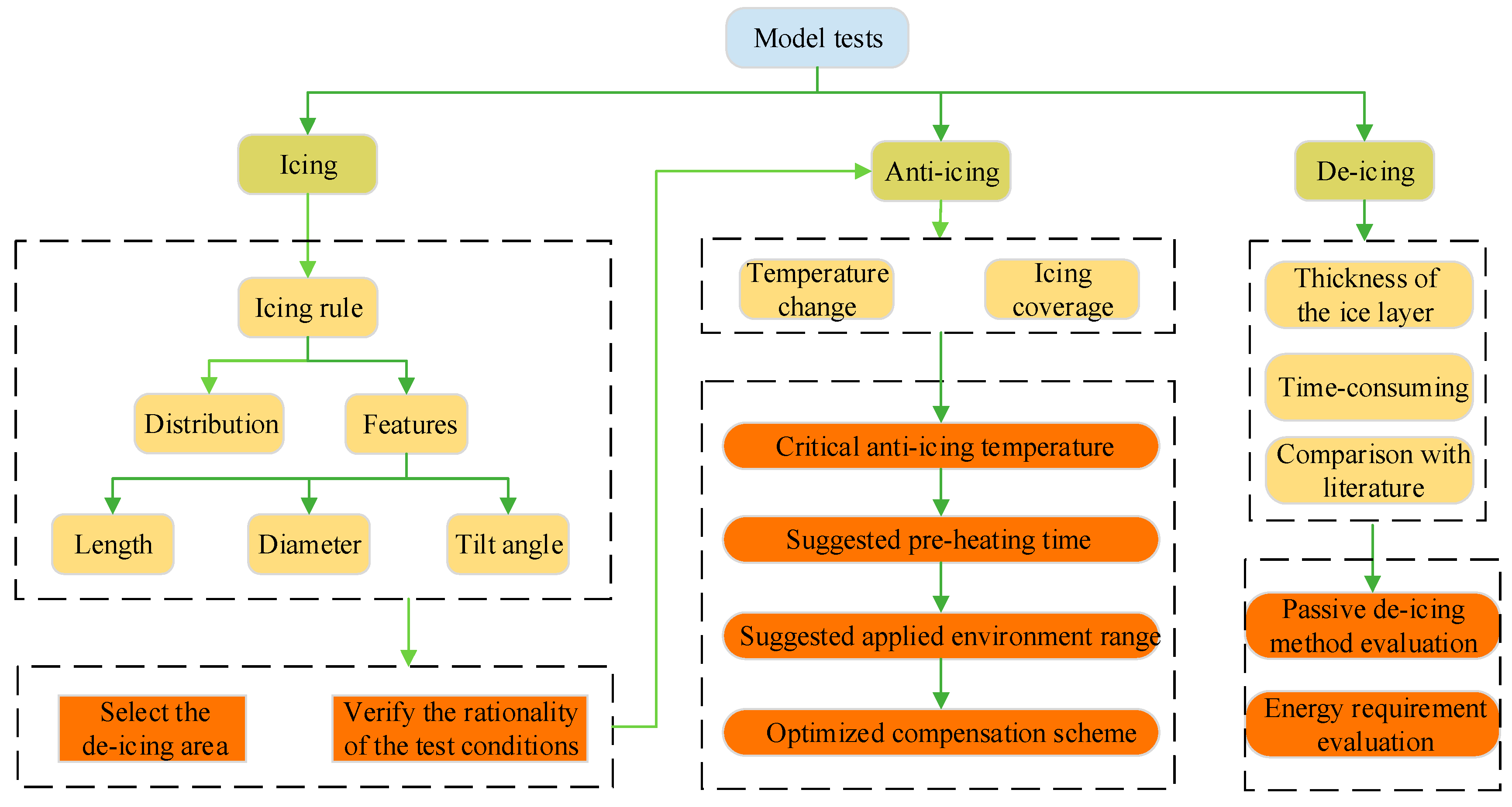
The main idea of this paper is to first obtain the icing characteristics of the beam through icing tests in order to develop targeted de-icing measures. Then, the heating system is installed in the selected de-icing area, and the de-icing tests are subsequently carried out. Finally, the test environment and heating method are changed to compare the de-icing effects under different conditions and to give a recommended de-icing solution. The schematic of the principal idea is shown in Figure 1.
The detailed technical scheme of this paper is as follows:
(1)
The icing characteristics (ice distribution and icing features) of the beam are obtained through pre-tests of the icing. By learning the ice distribution, a suitable de-icing area is selected. Subsequently, the growth rule of the icicles is assessed by analyzing the length, diameter, and tilt angle of the icicles, and finally, the reliability and stability of the test conditions are verified by comparing them with the established icing literature.
(2)
The heating system is installed at the selected area, and the anti-icing tests are carried out; these tests focus on recording the temperature change and the ice coverage of the heating system surface during the anti-icing process. The test results are analyzed to find the critical anti-icing temperature of the heating system and to give the recommended pre-heating time, a suggested environmental range for the heating system, and an alternative optimized compensation scheme.
(3)
Passive de-icing tests are carried out to obtain the de-icing time under different ice thicknesses. Subsequently, the passive de-icing of the heating system for the beams is evaluated qualitatively and quantitatively by comparing the relevant de-icing literature. The technical route is shown in Figure 2.

2.2. Test System and Working Relationships

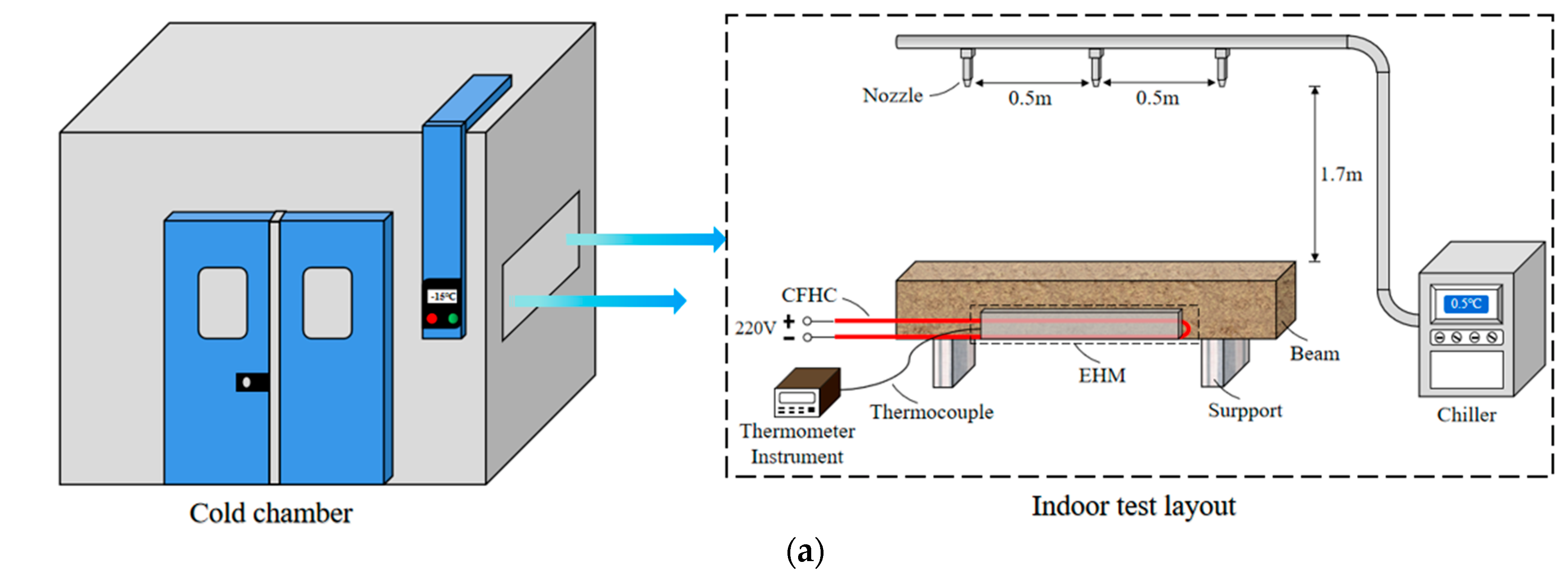
The model profiles for the icing and de-icing tests in this study are shown in Figure 3a; the working relationship between the test systems and the equipment is shown in Figure 3b.
The beam model for the experiment was a rectangular beam with a 0.5 m high support placed at the bottom to support the beam. Three nozzles were arranged above the beam at a 1.7 m distance as rainfall outlets and were connected to the external chiller through a water pipe. The chiller could reduce the water temperature to 0.5~1.5 °C. The above model and equipment were placed in the cold chamber, which was used to simulate the low temperature environment.
Five systems were used in the experiment: a spray system was used to simulate rainfall; a wind delivery system was used to provide wind; a heating system was used for the de-icing; a monitoring system was used to observe and record the test situations; and a data acquisition system was used to monitor and record the temperature changes.
The details of each test system and the equipment are as follows:
(1)
The spray system
The spray system is composed of a chiller and nozzles. The chiller is an air-cooled low-temperature chiller. The main function is to lower the temperature of the water to 0.5~1.5 °C and to speed up the icing process in a manner as close as possible to that of the practical situation. The nozzles are air atomization nozzles with an outlet diameter of 0.5 mm; the main function is to reduce the particle size of the raindrops to a certain extent, thus speeding up the condensation rate of the raindrops and making the icing easier. The number of nozzles is 3, each with a spacing of 0.5 m and a height of 1.7 m above the beam.
(2)
The wind delivery system
The wind delivery system is composed of a fan and a regulator. The fan is an axial fan with a power of 2 kW, a rated voltage of 380 V, an air volume of 18,700 m3/h, an air supply diameter of 610 mm, and a maximum wind velocity of 8 m/s. The main function is to simulate the wind condition. The regulator is a three-phase regulator, model TSGC2-3KVA, and by connecting in a series with the axial fan, the voltage of the fan can be changed, thus changing the wind velocity.
The icicles tilted inward after the wind was applied; thus, it was difficult to obtain good observations and photographs as the line of sight was blocked by the supports of the beam. Therefore, in order to better observe the tilt of the icicles after the wind was applied, the icing surface of the beam and the wind direction in the icing test were set as shown in Figure 4. An anemometer was used to measure the wind velocity in the range of 0.6~60 m/s, with an accuracy of ±3%.
(3)
The heating system
The heating system is composed of a stainless steel module, heat-insulated film, a carbon fiber heating cable (CFHC), and an external power supply. The main function is to generate heat to prevent the beam from icing.
(4)
The monitor system
The monitoring system is composed of cameras and video recorders. The main function is to monitor and record the test situation in real time for better analysis of the test process.
(5)
The data acquisition system
The data acquisition system is composed of thermocouples and a data collector. The thermocouple is a K-type, and the temperature measurement range is from −50 °C to +160 °C. The data collector can detect and record the temperature change in real time by connecting with the thermocouple.
(6)
Other equipment or models
Cold chamber: The step-in cold chamber (Figure 5a) is used to simulate the low-temperature environment, and its external dimensions are 10 m × 5 m × 2.8 m. The indoor temperature can be monitored and controlled by a touchscreen, and the provided temperature range is from −60 °C to 60 °C. The indoor temperature difference after stabilization is within 0.5 °C.
Temperature and humidity recorder: The temperature and humidity recorder (Figure 5b) is composed of a sensor and a display screen. The main function is to observe and calibrate the room temperature.
Concrete beam model: The concrete beam model is made at a scale of 1:30 in relation to the Wuhan Yangtze River Second Bridge, with the dimensions of 2 m × 0.2 m × 0.2 m. The length of the test area is 1.5 m, as shown in Figure 5c.

2.3. Test Procedure

2.3.1. Icing Tests

Step 1: Calibrate the precipitation
At the start of each icing test, the rainfall calibration is first required. In addition to the adjustment based on the self-contained flow meter, it is also necessary to measure the rainfall drops emitted at the outlet of the sprinkler system by using a rain barrel to ensure that the same amount of water is emitted from the spray system in each test.
Step 2: Start up the cold chamber
After the rainfall calibration is completed, the ambient temperature can be set as required, followed by the turning on of the cold chamber for 8 to 24 h to make the surface temperature of the test components reach the same as that of the set ambient temperature.
Step 3: Start up the spray system
When the surface temperature of the test component cools to the same temperature as the ambient temperature, the spray system can be started up for a continuous spraying period of 120 min. At the same time, the wind delivery system can be switched on simultaneously with the spray system according to requirements.
Step 4: Record the data
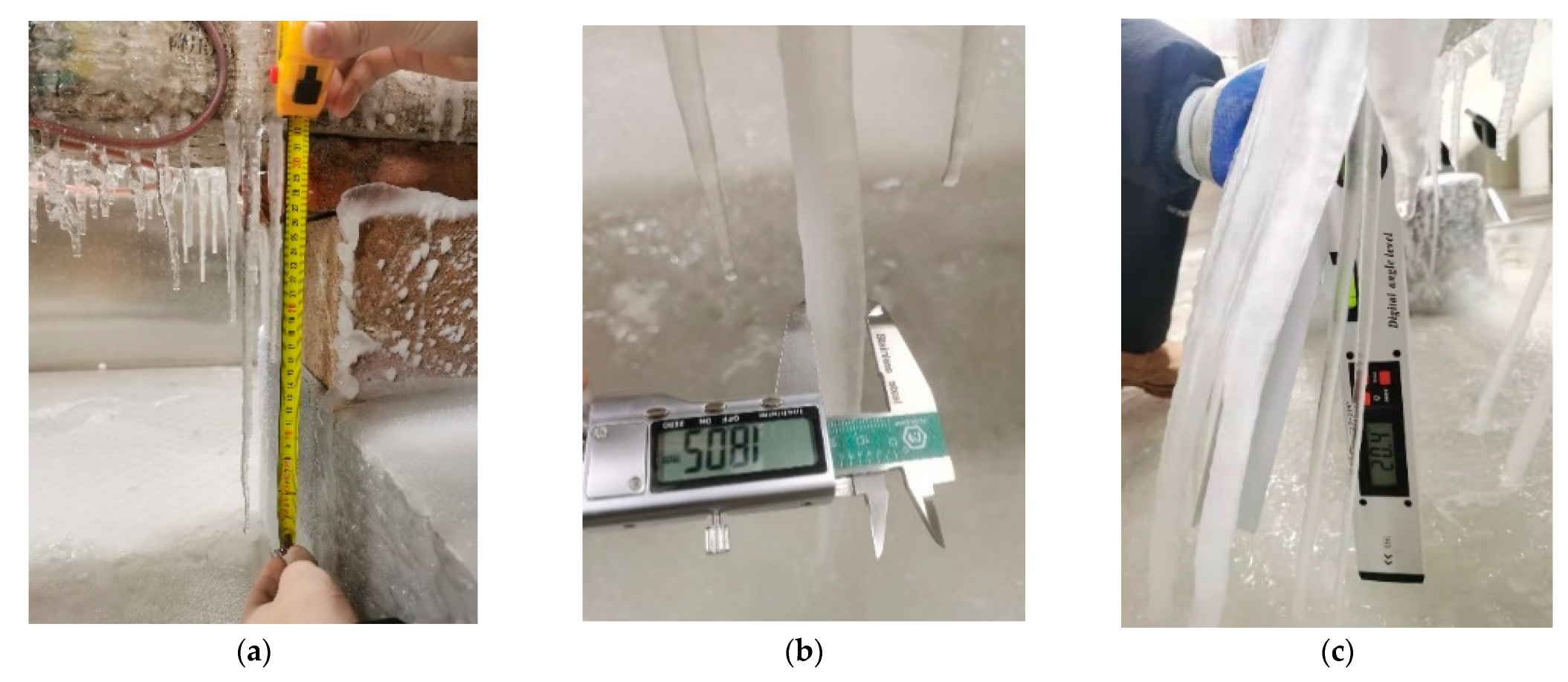
After 120 min of continuous spraying, the spraying was stopped. At the same time, the cold chamber was kept in continuous operation and manual access was gained to the chamber to take photographs of the icing of the beam and to measure the length, diameter, and tilt angle of the icicles using a tape measure, vernier caliper, and protractor (as shown in Figure 6), respectively. Considering that the icicles were not regular cylinders, the width of the thickest part of an icicle was used as the diameter of a single icicle in this paper. Finally, the video of the icing process from the monitoring system was saved and the images were captured for relevant qualitative and quantitative analysis.
Step 5: Measure the ice coverage
When measuring the ice coverage, the icing photographs should be taken at the same level; then, the photographs need to be cropped out, except for the icing components; then, the cropped image is placed in ImageJ software of version 2.3.0, and the area of ice coverage can be manually framed. The software is used to measure the percentage of pixels in that area to obtain the icing coverage.

2.3.2. Anti-Icing Tests

Step 1: Calibrate the precipitation (same as above)
Step 2: Start up the cold chamber (same as above)
Step 3: Start up the heating system
Once the surface temperature of the specimen cools to the same as that of the ambient room temperature, the heating system can be activated. The heating time depends on the required pre-heating time.
Step 4: Start up the spray system
The spraying system should be started up after a certain period of heating and should continue for 120 min. At the same time, the wind delivery system can be started up simultaneously with the spray system if required. (When carrying out passive de-icing tests, the fourth step needs to be exchanged with the third step and the heating time depends on the period it takes for the ice to melt.)
Step 5: Record the data (same as above)
Step 6: Measure the ice coverage (same as above)

2.4. Test Materials

2.4.1. Carbon Fiber Heating Cable (CFHC)

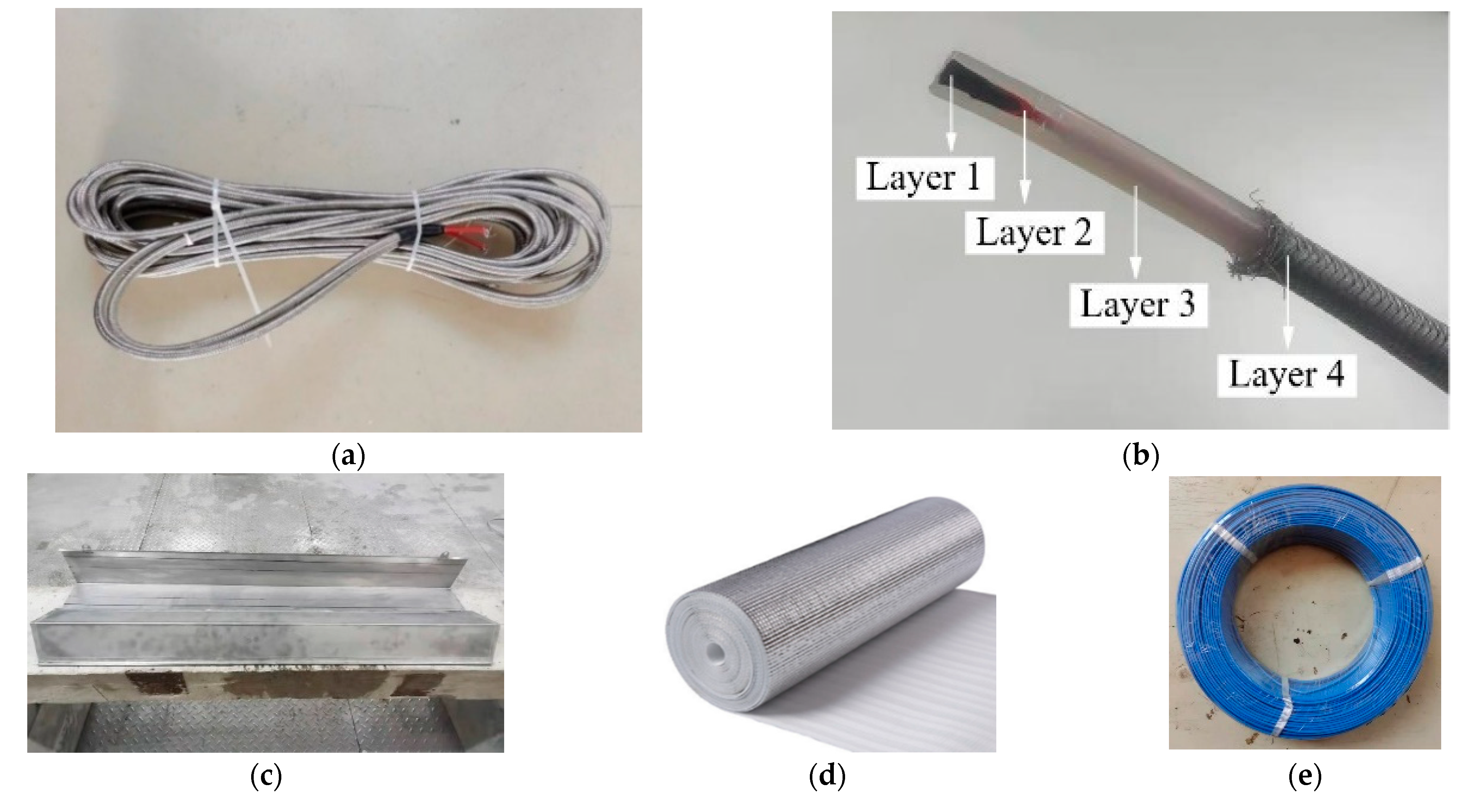
The CFHC is shown in Figure 7a. The structure of the CFHC is divided into four layers (Figure 7b): (1) the heating material—carbon fiber wire; (2) the electrical insulation material—Teflon; (3) the pressure-resistant and anti-corrosion material—polyethylene; and (4) the stainless steel material—the outer woven mesh. The main function of the outer woven mesh is to reduce the friction between the internal cable and the external sand and gravel. In this test, the cable was not subjected to a large amount of friction; so, the outer woven mesh was removed. The performance parameters of the CFHC are shown in Table 1.

2.4.2. Stainless Steel Module and Heat-Insulated Film

The stainless steel module (Figure 7c) is 304-type with a thickness of 0.5 mm. As a good conductor of heat, the heat transfer area of the CFHC can be effectively expanded by being in close contact with the stainless steel.
The thickness of the heat-insulated film (Figure 7d) is 5 mm. As the film is a poor conductor of heat, the heat can be insulated effectively, thus concentrating it in a certain direction.

2.4.3. Thermocouples

The thermocouples (Figure 7e) are K-type Teflon temperature measurement compensation wires. A total of three thermocouples were set in the heating system to record the surface temperature changes, and the temperature resistance range was −60 °C~+250 °C. The real-time temperature can be monitored and recorded by connecting with the Keysight data acquisition instrument. After the thermocouples were arranged, the temperature displayed by the data acquisition instrument was compared with that displayed by the temperature and humidity sensor and the touchscreen of the cold chamber, and it was found that the temperatures of the three were very close to each other, with an error of only 0.2 °C.

2.5. Design Idea of the Heating System

In roadway de-icing applications, heating cables are usually pre-buried into the structure during road construction, or a slot is created to embed the heating cables in the existing roadway. However, this paper focuses on the study of existing bridges, and the method of pre-burial during construction is clearly not in line with the focus of this paper. If the beam is slotted, it will be more difficult to construct. The difference between road and beam is that the road surface is often occupied by human and vehicular activity, whereas the surface of the beam basically does not involve human activity; so, a heating system with carbon fiber heating cables as the heat source can be considered for direct placement on the surface of the beam.
If the CFHCs are set directly on the surface of the beam to heat the beam, the heating effect may not be obvious due to the influence of the surrounding environment. Therefore, after setting the CFHC, a layer of stainless steel sheets can be laid on the surface of the heating cable to extend the heat transfer range of the CFHC and directly change the icing surface of the beam from the original concrete surface to the metal surface at the same time. Finally, a layer of heat-insulated film can be set on the contact surface of the heating cable and the beam to concentrate the heat transfer to the metal surface and enhance the heat transfer efficiency again. (The specific layout can be seen in Figure 8, section I-I.)
The external size of the heating system was 1 m × 0.1 m × 0.01 m. Three K-type thermocouples, named A, B, and C, were placed inside the heating system to record the temperature changes, and the spacing of each was 0.25 m, as shown in Figure 8. The layout spacing of the CFHC was 8 cm; the upper CFHC was 2 cm away from the top of the heating system; and the corresponding thermal power density was 576 W/m2. The thermocouples were all 40 mm away from the two CFHCs. As the thickness of the metal plate was only 0.5 mm, the temperature difference between the inside and outside of the metal plate was negligible. The I-I section in Figure 8 shows the internal details. The CFHCs and thermocouples were stuck to the front surface. The aluminum film was close to the beam face to insulate the heat. The shaded area in Figure 8 shows the adjusted layout of the CFHC.

3. Pre-Tests of Icing and Analysis of Results

Icing is a complex process with great randomness [15]. Various climatic conditions, such as ambient temperature [16], wind velocity [17], atmospheric water content [18], the particle size of atmospheric water droplets [19], and the shape or surface roughness [20] of the icing components, are the key factors affecting icing. Therefore, before conducting de-icing tests, it was necessary to carry out several icing tests. By analyzing the variation of icicle size in the environment and comparing it with the icing rules in the existing literature, the rationality and stability of the test conditions were verified to reduce the influence of randomness on the test. In addition, the icing characteristics and the specific icing location of the beam can be obtained by icing tests, which can help in the selection of a suitable de-icing area and the development of targeted de-icing measures.
In order to present the icing effect more obviously, the ambient temperatures of the tests were chosen to be −5 °C, −10 °C, and −15 °C, respectively. According to the meteorological data and fieldwork, the wind velocity range of the Wuhan Yangtze River Second Bridge in winter is about 2.4 m/s to 5.1 m/s when there is wind; therefore, the wind velocities of the test were chosen to be 3 m/s and 5 m/s, respectively. Five groups of icing tests were conducted, and the test conditions are shown in Table 2. The wind direction is shown in Figure 4.

3.1. Icing Distribution

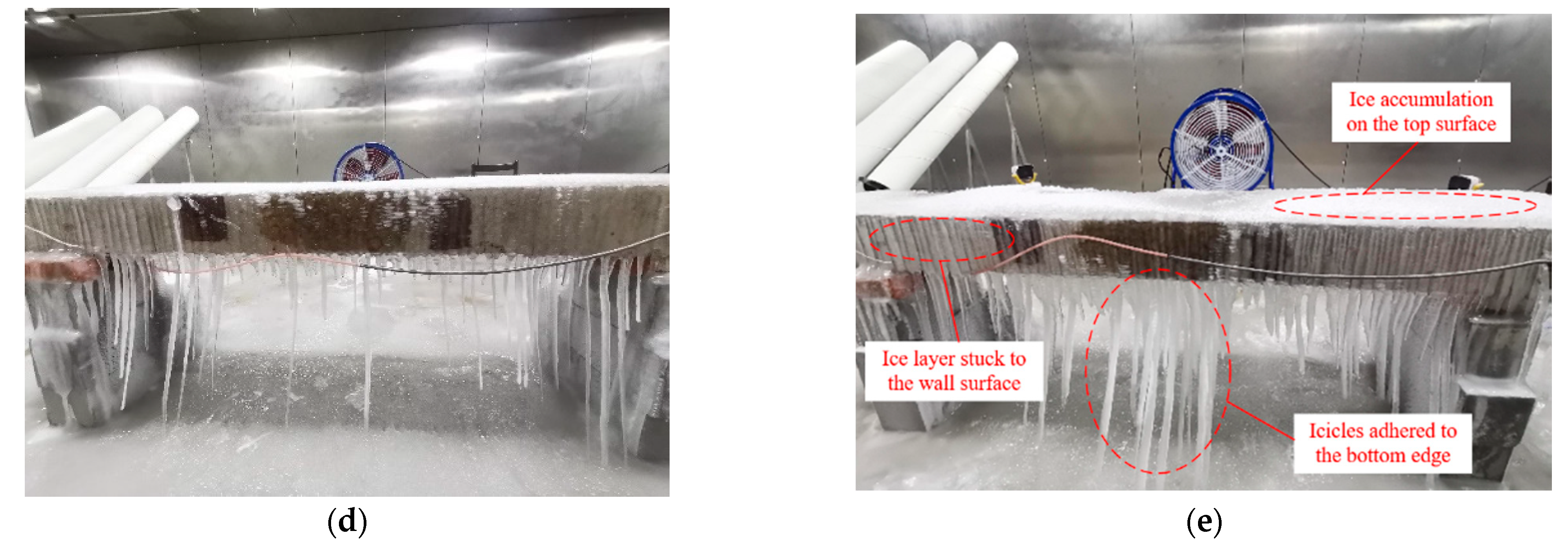
As can be seen in Figure 9, in the five groups of icing tests the icing position and the shape of the beam were roughly the same, but the icing degree was different. The top and front surfaces of the beam were all iced, and massive icicles were attached below the beam. At the same ambient temperature, the ice layer on the wall surface was harder and denser than that on the top surface, but the ice thickness was not uniform. With the deterioration of the environment, the icing degree of the beam increased significantly. The icicles tilted, especially after the wind was supplied.
The top and side surface of the beam in the spray range were almost completely frozen, and a large number of icicles were attached to the bottom edge. If one attempted to set up de-icing modules in all the icing areas, the workload would undoubtedly be considerable, whether in the test or in the practical project. Therefore, it was beneficial to select a suitable area for the deicing tests. In general, the ice on the beam can be divided into three parts: the ice accumulation on the top surface of the beam; the ice layer stuck to the wall surface of the beam; and the icicles adhering to the bottom side of the beam. In comparison, the damage caused by falling sharp icicles is obviously more serious. Therefore, this paper chose to install the heating system at the bottom edge of the beam and focus on the de-icing strategy in this area.

3.2. Icing Features

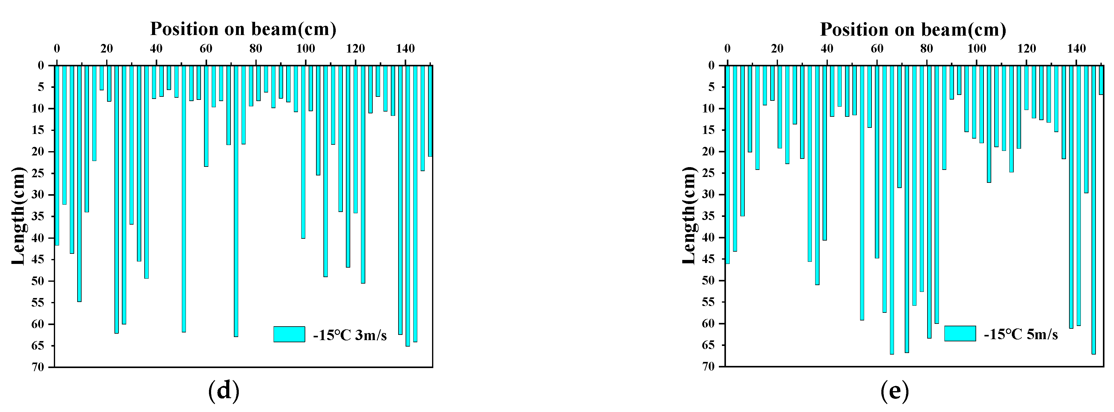
The icing test results were quantified to more accurately summarize the icing rule of the beam, thereby verifying the reliability of the test conditions and providing standards for subsequent anti-icing tests. The distribution of the icicles was roughly drawn in the form of a histogram, as shown in Figure 10. Only the icicle length is shown in the figure; the diameter is ignored, and the spacing between the icicles is assumed to be equal. The vertical axis of the histogram represents the icicle length, and the horizontal axis represents the position on the beam. Among them, the length of the beam between the two supports is 1.5 m, which is the length of the horizontal axis. The supports on the left and right sides are used as the coordinate origin and end point, respectively. Moreover, the variation of the icicle size (length and diameter) is shown in Figure 11.
The icicles on the beam were different in length, and the distribution of the long and short icicles was irregular. As can be seen in Figure 10a–c, as the ambient temperature decreases, the column density increases and the blank area decreases, meaning that the number of icicles increases and that the overall length of the icicles shows an increasing trend. When the ambient temperature reached −15 °C, the distribution density of icicles reached a saturation state. Figure 10d,e present the icicle length distribution after applying wind. It can be seen that after the wind is applied, the distribution density of the icicles is still in a saturated state, but the blank area continues to decrease, indicating that the overall length of the icicles further increases. Overall, in the laboratory rainfall icing tests, with the continuous deterioration of the environment, the distribution density of the icicles on the beam will reach a saturation state, and the overall length of the icicles will continue to increase.
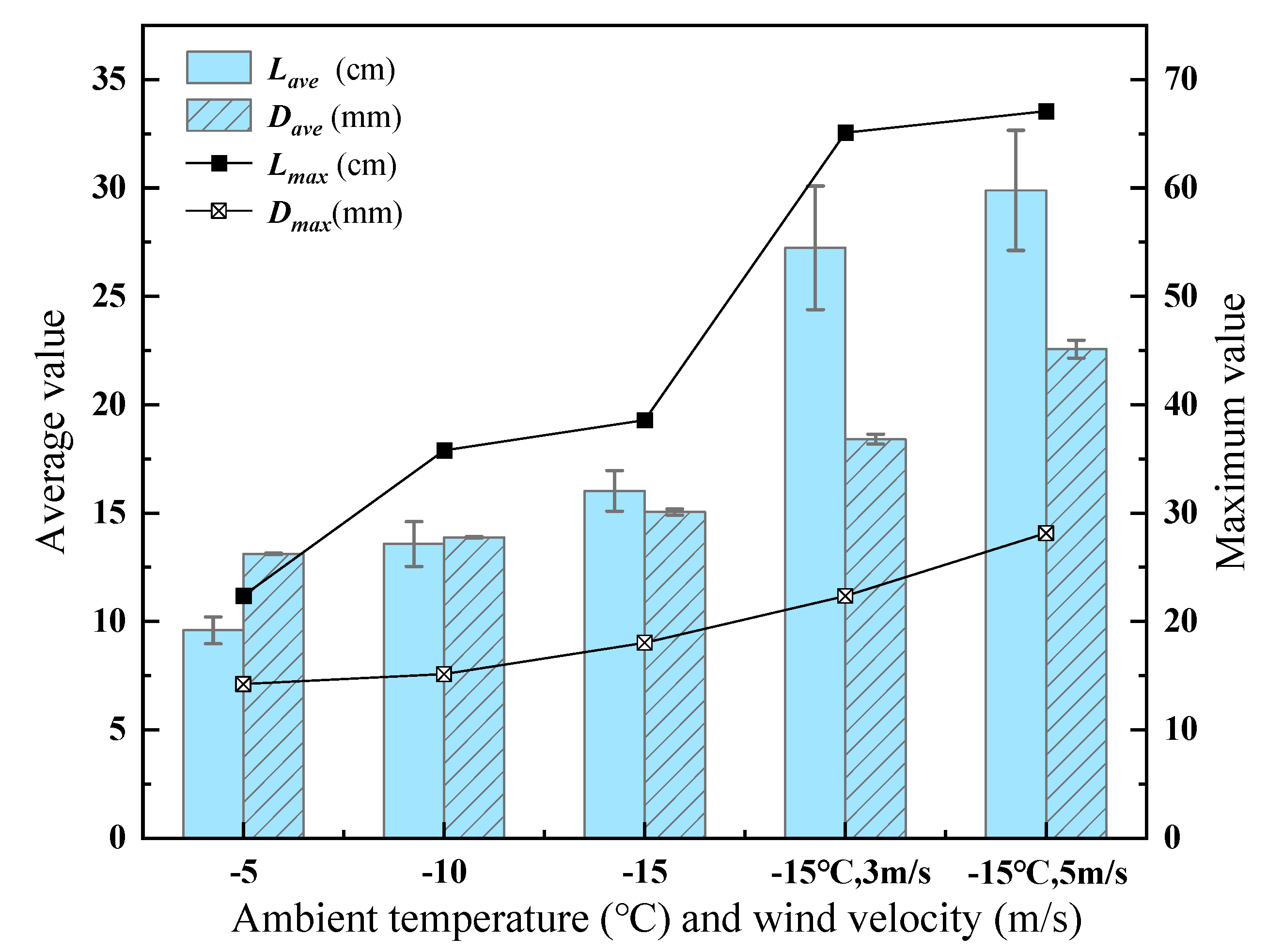
The dimensions of the icicles are recorded in Table 3. A a columnar–dotted line composite graph of the changing of the size with the environment was drawn, as shown in Figure 11. It can be seen that both the length and the diameter of the icicles increase as the ambient temperature decreases. However, in the two different temperature ranges (−5 °C to −10 °C and −10 °C to −15 °C), the two growth rates of the icicles are obviously different. The increments of Lmax and Lave in the first temperature range were 13.4 cm and 3.99 cm, respectively. Due to the decrease in ambient temperature, a large amount of rainwater froze on the way to the icicle tip, resulting in the increments of the second interval being only 2.8 cm and 2.44 cm; thus, they decreased by 79.1% and 38.85%. Correspondingly, the diameter of the icicles showed the opposite trend. For example, the increments of Dmax and Dave in the first interval were 0.91 mm and 0.76 mm, respectively, and 2.91 mm and 1.17 mm in the second interval; thus, they increased by 219.78% and 53.95%. These data show that when the ambient temperature continues to decrease, the diameter and length of the icicle will increase, but the length increment will decrease; the diameter increment will increase instead, and the icicle will grow more in the radial direction.
After the wind was supplied, the length and diameter of the icicles showed a similar growth rule. The growth trend of the icicle length changed from gentle to steep, while the wind velocity increased from 0 to 3 m/s. This is because the lower wind velocity changes the air convection around the icicle and causes the droplets in the air to have a horizontal velocity component; this accelerates the attachment to the icicle, thereby accelerating the growth of the icicle [21]. When the wind velocity increases to 5 m/s, a large number of raindrops freeze midway in the flow to the tip of the icicle [22]; this leads again to a slowing growth trend. The growth trend of the icicle diameter was first slow and then fast. In addition, the icicles also tilted due to the influence of the wind, and the maximum tilt angles of the icicles under the wind velocities of 3 m/s and 5 m/s were 20.4° and 22.7°, respectively.
In this paper, the growth of the length and diameter of the icicle was restrained, and the trend of the icicle length growth was slowed by radial growth. This conclusion is consistent with a study by Makkonen in 1988. The study also points out that long icicles grow only when there is almost no wind or when the water supply is large enough (e.g., spray icing) [23]. That means that in the absence of wind or a low water supply, icicles will only grow in one direction (lengthwise or radially), while in harsh environments (spray icing), icicles will grow in both directions at the same time.
To sum up, the icing features obtained by the five groups of icing experiments under the spray system in this paper showed a certain regularity, and this regularity is consistent with the two studies by Makkonen in 1988 and 1998. Therefore, the icing conditions selected in this paper, such as 1 mm/min precipitation, ambient temperature, and wind velocity, are reasonable conditions to satisfy icing, and the test conditions provided by the test equipment and systems in this paper show a certain degree of stability. Therefore, the following anti-icing tests were carried out in accordance with the standards of the icing tests.

4. Results and Analysis of De-Icing Tests

4.1. Anti-Icing Tests

4.1.1. Critical Anti-Icing Temperature

The critical anti-icing temperature is the critical temperature at which a component will be ice-free. The critical anti-icing temperature is different under different environments, and finding the critical anti-icing temperature can help to obtain the suitable pre-heating time. The specific method is as follows: when the temperature of the specimen reaches the same as the ambient temperature, turn on the heating and spray system at the same time, and the surface of the heating system will freeze first and then melt; record the temperature at the melting time as the critical anti-icing temperature of each group; repeat the test several times; and finally, take the average value as the critical anti-icing temperature.
Five sets of anti-icing tests were carried out to obtain the critical anti-icing temperature. All the tests were carried out at −15 °C in a windless environment, with precipitation of 1 mm/min, a rainfall time of 120 min, and a pre-heating time of 0 min (the heating and spray systems were started up at the same time).
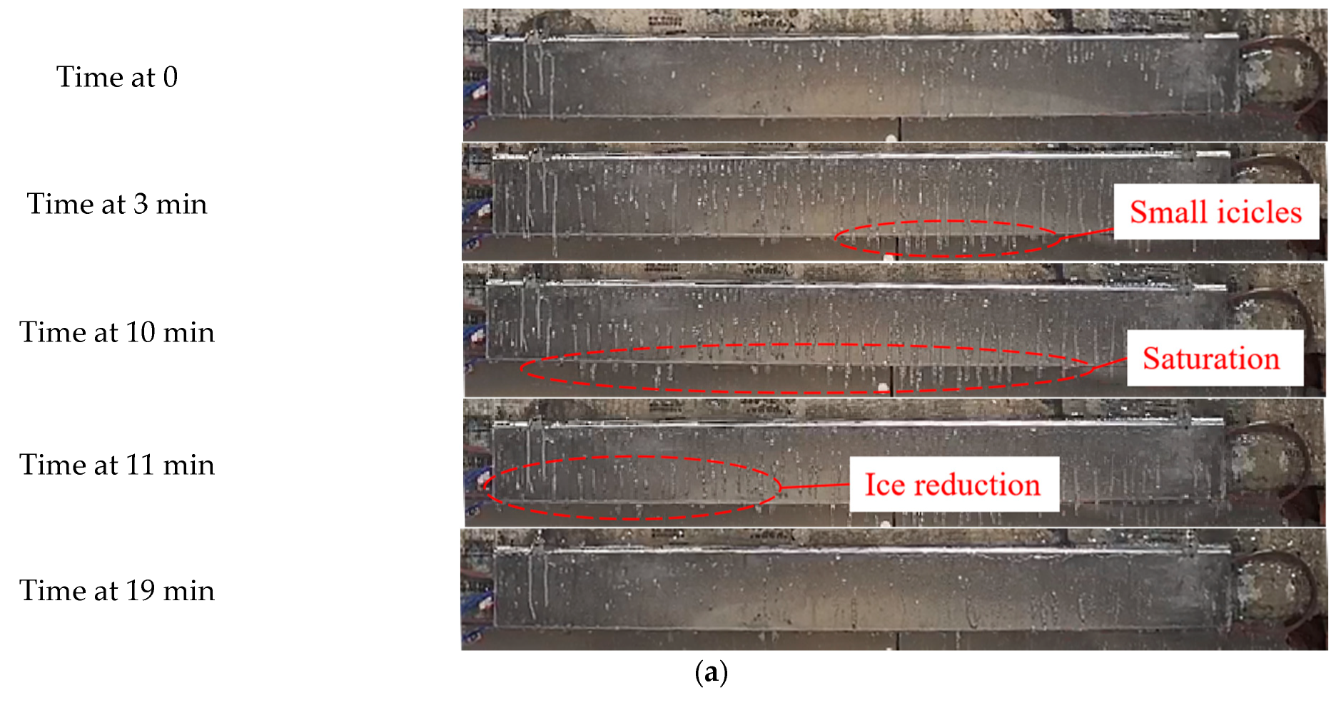
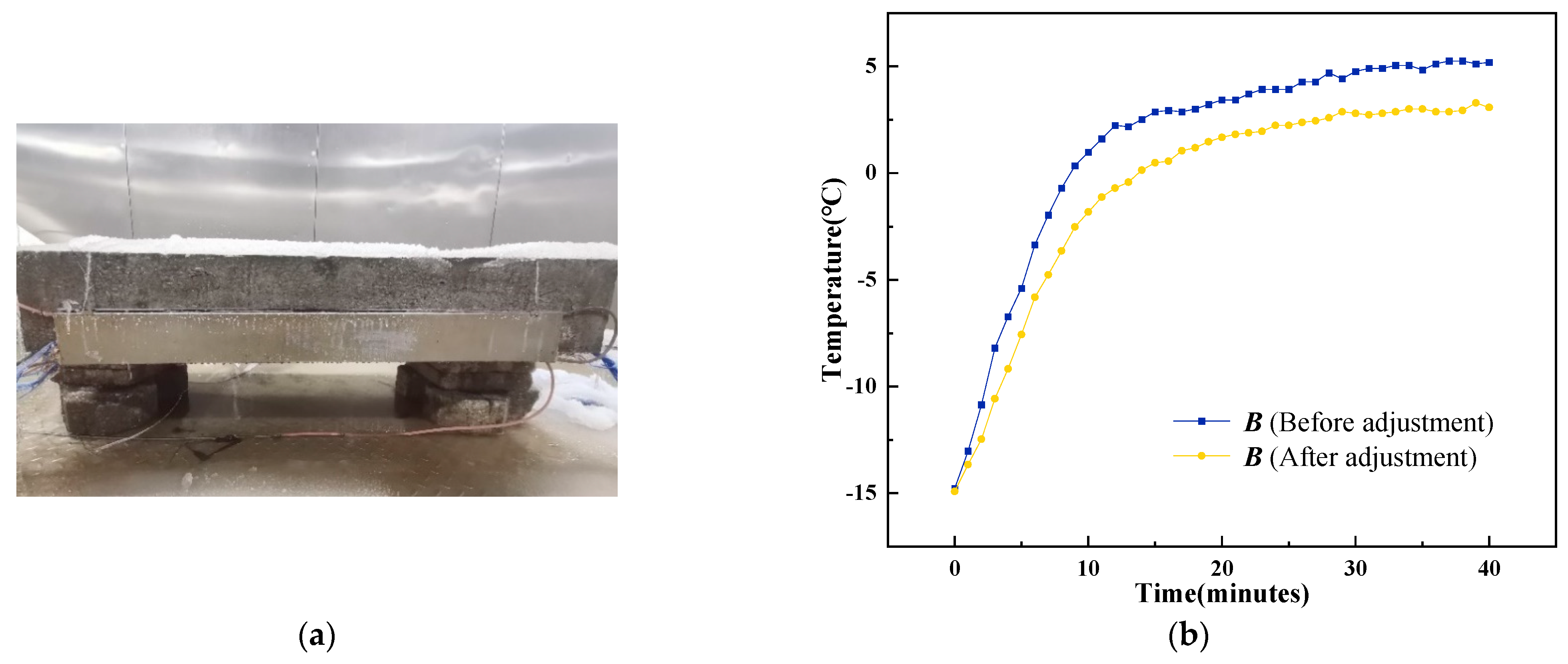
Figure 12a shows the icing and melting process of the heating system surface under a no pre-heating condition. The time when the heating and the spray system were turned on was recorded as time 0. At the time of 3 min, the heating system surface started to freeze due to the insufficient heat generated by the CFHC. A few small icicles could be seen on the bottom edge, and the number of icicles continued to increase. At the time of 10 min, the icing reached saturation due to the increased temperature. At the time of 11 min, the icicle on the left part melted and fell off. This means that the ice may begin to melt at close to 10 min and is in a state of saturation to be melted. The ice was all melted at the time of 19 min. Similar phenomena were shown in the five groups of experiments, and the temperature rise law of the heating system surface was also relatively close, as shown in Figure 12b.
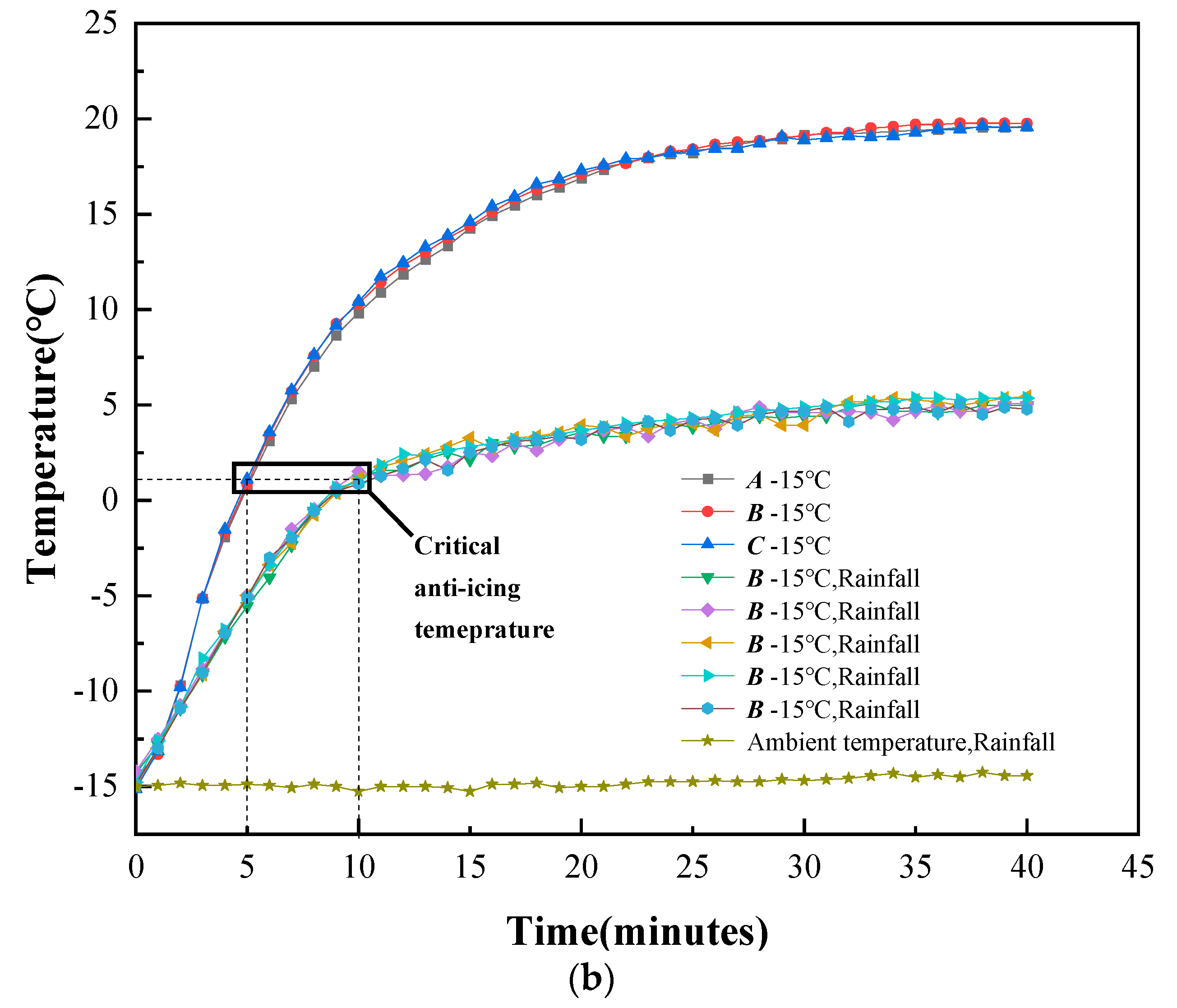
It can be seen in Figure 12b that the temperature of the heating system surface increases first and then tends to be stable after heating with electricity. During the heating process, the temperatures of the three thermocouples were close, indicating that the horizontal temperature distribution on the surface of the heating module was uniform; so, thermocouple B was chosen to represent the temperature change on the surface of the heating system in the subsequent experiments. Under rainfall conditions, since the raindrops take away a certain amount of heat, the final stable temperature will be greatly reduced, with a temperature difference of about 14 °C. At the time of 10 min, the temperature rise rule of all five groups of tests showed a cooling trend. The reason for this may be due to the change in the ice accumulation pattern on the heating system surface. In the first ten minutes of rainfall, some raindrops stay on the surface of the heating system. Due to the temperature difference, the heat of the raindrops is taken away by the surface of the heating system and the air, thereby forming ice. At the same time, due to the interaction, the surface temperature of the heating system will increase accordingly because the temperature of the surface of the heating system at this time is much lower than the temperature of the raindrops. In addition, some ice layers generated by icing will cover the heating system surface, resulting in a reduced heat transfer surface and a slight increase in the temperature rise rate. After 10 min, as the temperature of the heating system surface rises, a large number of cold raindrops will take away the heat, resulting in a lower heating rate.
In the five groups of anti-icing tests, the icing and melting phenomena on the surface of the heating system and temperature rise rules both showed relative consistency. At the time of 3 min, the surface of the heating system began to ice and saturation was reached at the time of 10 min. Therefore, this paper chose the temperature at the time of 10 min as the critical anti-icing temperature. The average temperature value at the time of 10 min in the five sets of tests was taken as the critical anti-icing temperature under a −15 °C environment; this temperature was 1.12 °C.

4.1.2. Suggested Pre-Heating Time

Giving the suggested pre-heating time can help to save electrical energy. Combined with the temperature rise rule of the heating system, the time tp required to reach the critical anti-icing temperature can be obtained. Then, the pre-heating time is controlled within tp ± 2 min in order to conduct five anti-icing tests to reduce the occasionality. Finally, the final anti-icing effects of the different tests are compared, and the suggested pre-heating time is given in a combination with the temperature change of the heating system at the “freezing moment” (the freezing moment means the moment when the surface of the heating system begins to icing under the no pre-heating condition, it can be concluded from Section 4.1.1 that the freezing moment is 3 min)
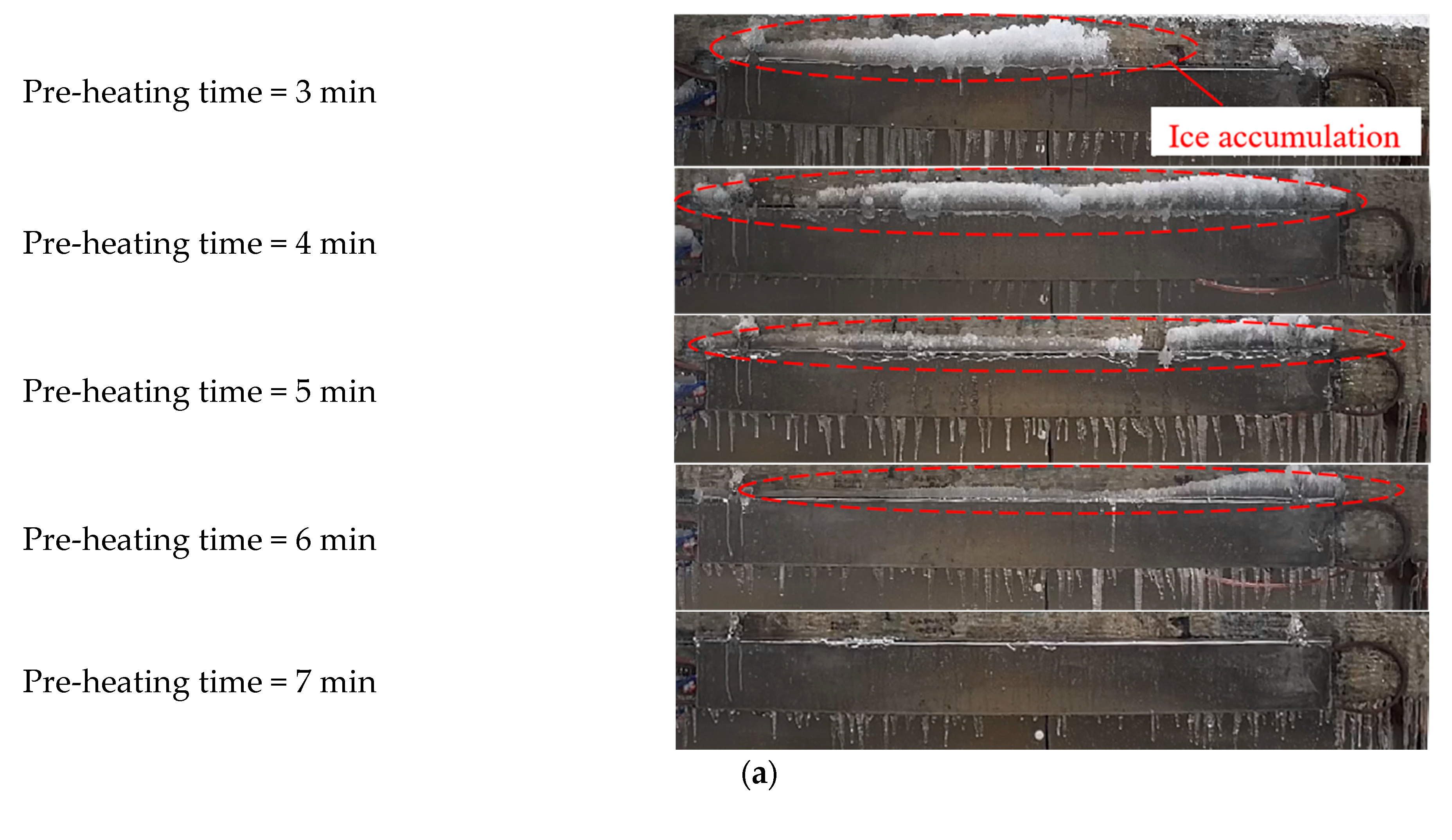
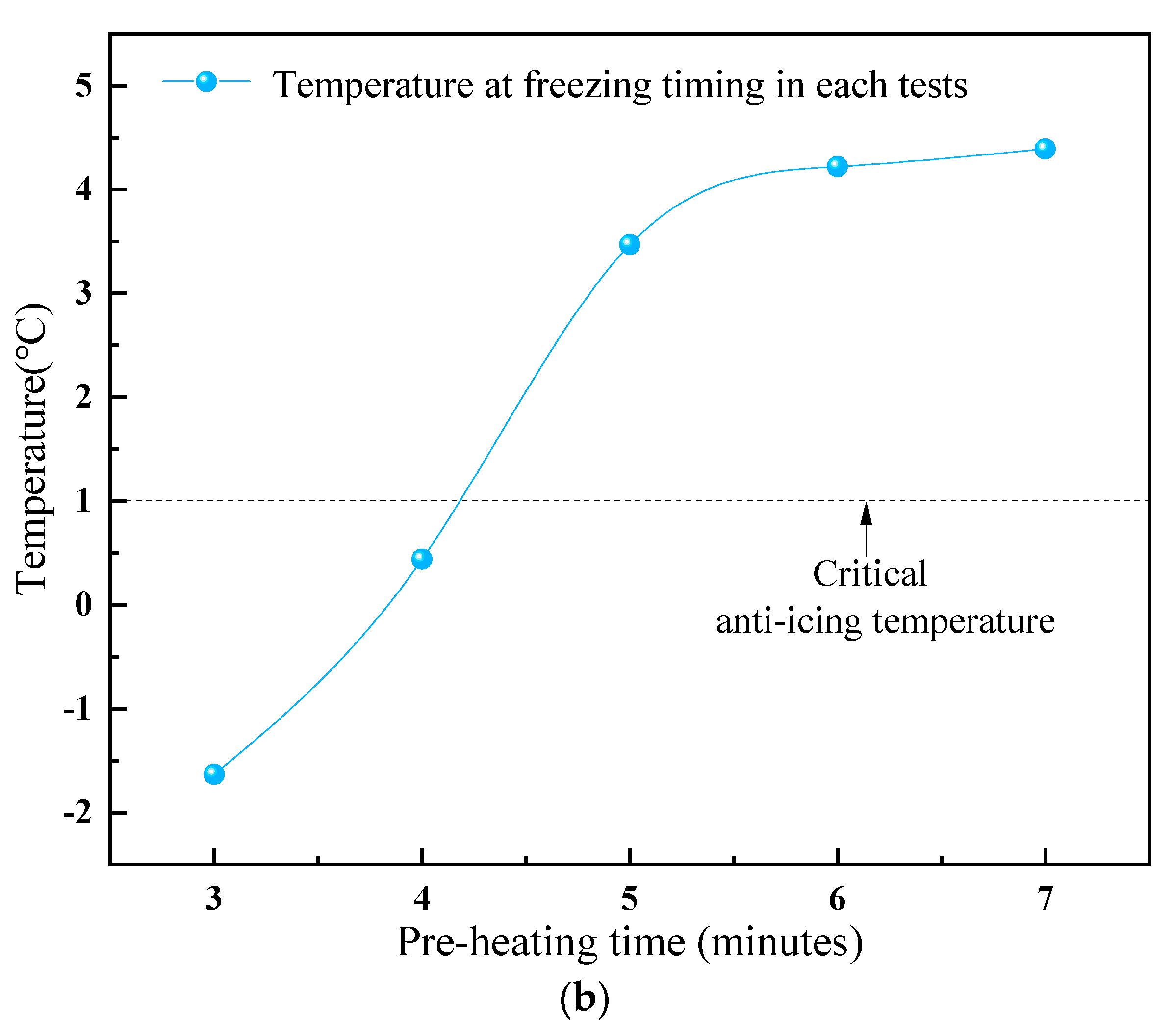
The specific method is as follows. The critical anti-icing of the heating system at −15 °C ambient temperature is 1.12 °C. Combined with the temperature rise law of the heating system, it can be concluded that the time required to reach close to 1.12 °C is 5 min (as shown in Figure 12b). Therefore, 5 min was used as the basic pre-heating time to conduct anti-icing tests. Then, four groups of anti-icing tests with pre-heating durations of 3, 4, 6, and 7 min were conducted for comparison. The ambient temperature was −15 °C; the wind velocity was 0; the precipitation was 1 mm/min; and the rainfall time was 120 min. The effects of the five sets of anti-icing tests are shown in Figure 13a, and the temperature of the heating system at 3 min (freezing moment) in each anti-icing test is shown in Figure 13b. The start time of rainfall was recorded as the initial time moment.
In the five sets of anti-icing tests with different pre-heating times, after 120 min of spraying, there was no ice accumulation on the front surface of the heating system and no icicles attached to the bottom. This indicates that the anti-icing effect can be achieved by pre-heating the heating system. However, a large amount of ice accumulated on top of the heating system. As the pre-heating time increased, the ice accumulation on the top decreased. The reason may be that the short pre-heating time failed to transfer enough temperature to the top of the heating system, resulting in a large ice accumulation. Therefore, an optimized compensation scheme to solve the top ice accretion is proposed in Section 4.1.4.
It can be seen in Figure 13b that with the increase in the pre-heating time, the temperature of the heating system at the 3 min moment (freezing time) gradually increases. When the pre-heating times are 3 and 4 min, the temperatures at the freezing times are lower than the critical anti-icing temperature. It means that when the pre-heating time is less than 5 min, there is still the possibility of freezing on the surface of the heating system. In the latter three pre-heating anti-icing tests, the temperatures of the heating system at the freezing time all exceeded the critical anti-icing temperature.
Lower pre-heating times carry the risk of icing, while higher pre-heating times cause energy waste [3]. In general, the pre-heating time of the heating system is recommended to be no less than 7 min under windless conditions.

4.1.3. Suggested Environment Range of Application

The ambient temperature [23] and wind velocity [4] are crucial factors that affect the electric heating de-icing. The wind velocity on a bridge crossing a river is usually higher than in urban areas. When the environment is too harsh, the heating performance of the heating system will be greatly affected, the anti-icing for the beam may fail, and a serious icing situation may occur again. However, when the icing coverage ratio reaches a certain degree or covers the whole surface of the heating system, the heating performance of the heating system may be less affected by the wind due to the ice cover preventing the wind. Conversely, the ice layer may fall off faster due to the internal heating caused by the heating system. Because the ice-falling situation tends to occur after the ambient temperature rises, the ice does not come off easily when the outward environment of the icing is relatively stable. In contrast, if the external environment of the icing is relatively stable and the internal temperature of the component rises, the ice accumulation is likely to fall off more quickly relative to the natural shedding situation, and after the ice falls off, the surface of the heating system will freeze again due to low temperature; this process of icing and melting will be repeated. In such a case, bridge traffic safety may be threatened more quickly and more frequently. Therefore, it is necessary to find out the applicable environmental range of the heating system, beyond which it may be safer to shut down the heating system because thicker ice accumulation in the stable low-temperature environment is more strongly adsorbed to the components than that in a warmer environment [24].
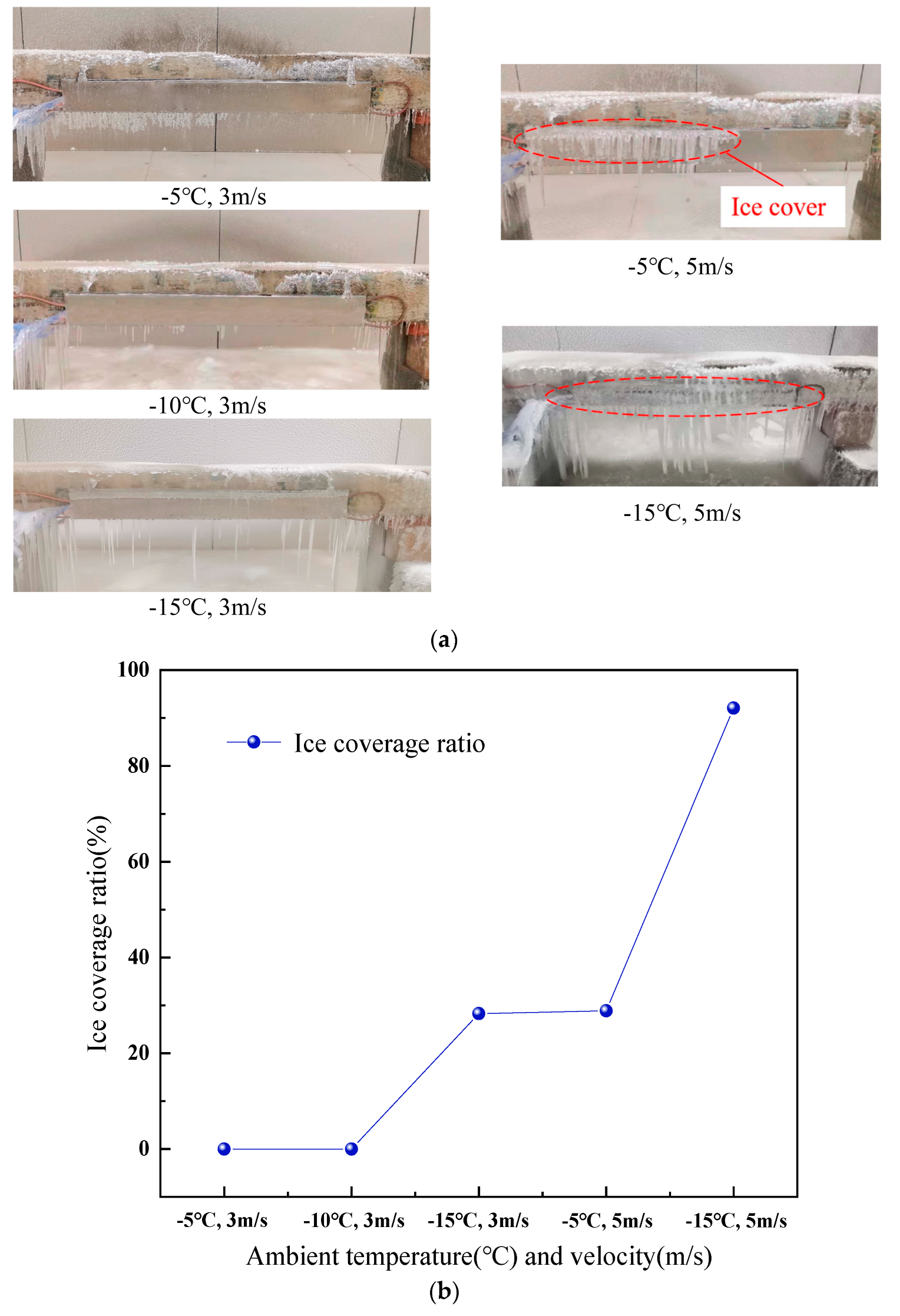
Five groups of anti-icing tests were carried out by changing the ambient temperature and wind velocity. By calculating the icing coverage of each group of tests, the suggested applicable environment range is given. The test conditions and icing coverage are shown in Table 4. Figure 14a shows the effects of the five groups of anti-icing tests, and Figure 14b shows the variation of the icing coverage with the environment.
When the wind velocity was 3 m/s, after 40 min of pre-heating, the heating system surface was free of ice at −5 °C and −10 °C (Figure 14a). At −15 °C ambient temperature, the ice was accumulated on the leading edge of the heating system, and the shape was a long strip of ice. By calculating the area proportion of the icing area, the icing coverage ratio was obtained; it was 28.27%. When the wind velocity increased to 5 m/s, the leading edge of the heating system not only froze but also generated a few icicles outward. At −15 °C in particular, the heating system almost lost the anti-icing performance, and the icing coverage was as high as 92.07%. Only the area within the diameter of the CFHC was free of ice. This shows that wind has a serious impact on the anti-icing performance of the heating system. When the ambient temperature is at a low level or the wind velocity is high, the heating system almost loses the anti-icing performance, and the ice will cover the surface of the heating system in a large area. In addition, since the internal heat source is still generating heat, the risk of ice falling in the heating system-equipped area may occur more quickly when the icing stops.
In the five groups of anti-icing tests under windy conditions, three groups were iced. When the wind velocity was 5 m/s, the surface of the heating system froze in both sets of tests. When the wind velocity was 3 m/s, the surface of the heating system only froze in an environment of −15 °C. Therefore, the applicable environment range of the heating system should be adjusted according to the wind velocity.

4.1.4. Compensation Scheme

According to the anti-icing tests in Section 4.1.2 and Section 4.1.3, when the pre-heating time is short, the temperature on the top surface of the heating system may not reach the temperature required for anti-icing, resulting in a large amount of ice accumulation on the top. As the ice accumulation continues to increase, there is also a risk of falling ice. In order to solve this hidden danger, this section proposes an optimized compensation scheme, which is to move the upper CFHC to the top platform surface of the heating system (as shown in Figure 8), thereby accelerating the heat transfer. The anti-icing test was carried out under the conditions that the ambient temperature was −15 °C, the wind velocity was 0, the precipitation was 1 mm/min, and the pre-heating time was 3 min.
After 120 min of spraying, the front and top surfaces of the heating system were not frozen. Compared with the solution before optimization, under the same short-time pre-heating conditions, the ice accumulation problem on the optimized heating system was significantly improved. It shows that by moving the CFHC to the top surface, the temperature supply rate can be accelerated, and the anti-icing effect can be achieved even under short-time pre-heating conditions. Therefore, increasing the supply rate of the temperature in the platform surface is beneficial for anti-icing. At the same time, according to the temperature rise rule recorded by the thermocouple B on the surface of the heating system (Figure 15b), it can be seen that after moving the heat source to a further distance from the thermocouple, the temperature rise trend at the thermocouple is still relatively close; both rise first and then tend to be stable, but the increase in temperature is significantly lower than before the adjustment. After 40 min of heating, the temperature difference before and after the adjustment was about 2 °C.
The problem of ice accumulating on the heating system platform area can be effectively solved by adjusting the arrangement of the CFHC, but with the increase in heat source spacing, the temperature at a distance from the heat source will decrease; so, the thermal power density of the heating system should be determined later, according to the comprehensive consideration of the environment in which it is located.

4.2. Passive De-Icing Tests

4.2.1. Passive De-Icing Evaluation

When the anti-icing fails, the heating system can be turned on again after the storm weather ends for passive de-icing. Coupled with a certain time of traffic control, the purpose of eliminating security risks can be achieved.
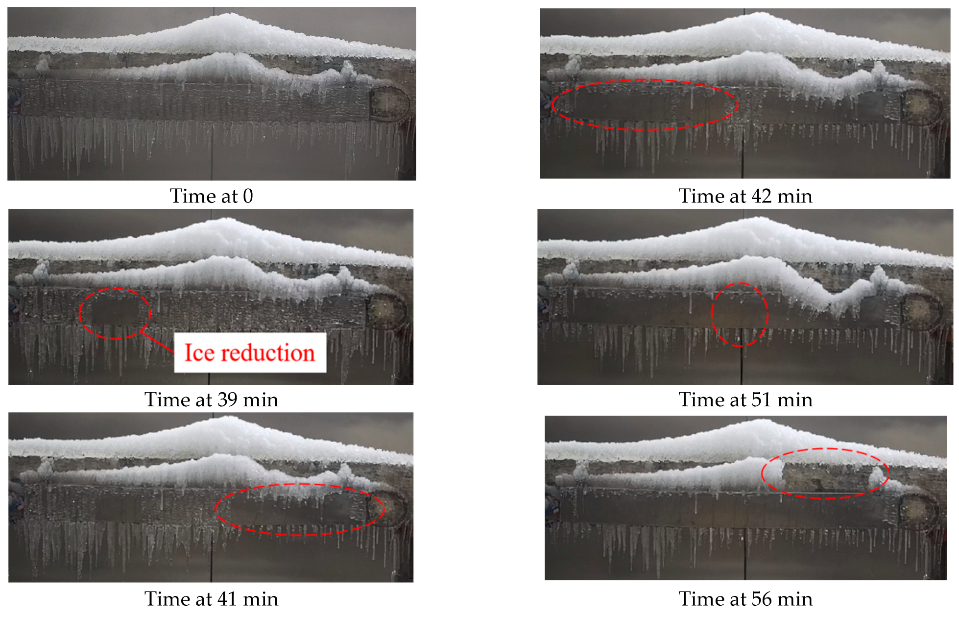
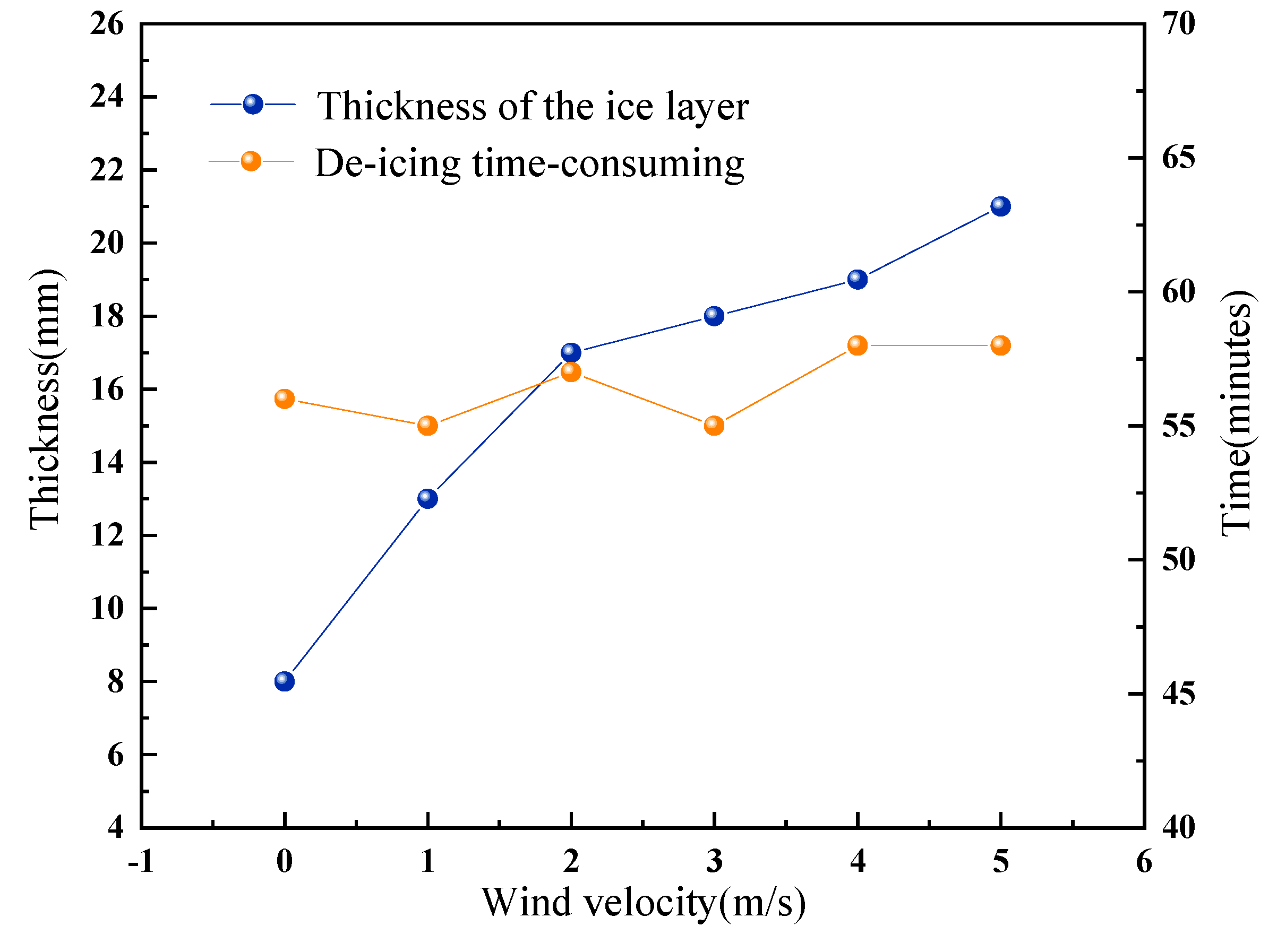
Six groups of passive de-icing tests were carried out, and the test conditions are shown in Table 5. The test procedures of the passive de-icing tests comprise first freezing the ice and then melting it. Firstly, the heating surface was sprayed for 120 min; then, the spray system or wind delivery system was turned off, and the ambient temperature was kept constant. Finally, the heating system was turned on, and the ice melting situation was observed. Figure 16 shows the ice melting process when the wind velocity was 0, and Figure 17 shows the relationship between the de-icing time period and the wind velocity.
The initial time of heating was recorded as time 0. At the time of 39 min, due to the increase in internal temperature, the ice layer in the left part of the heating system surface began to fall off. In the following three minutes, a large area of ice fell off. By the time of 51 min, the ice layer on the wall surface of the heating system was almost completely removed. At the time of 56 min, the extended ice on the top surface of the heating system fell off, and the ice melting process ended.
The de-icing time periods for all six groups of tests were less than 60 min, with an average value of 56.5 min, and the difference between the longest and shortest de-icing time was only 3 min. As can be seen in Figure 17, as the wind velocity increases, the ice thickness on the heating system surface increases significantly. However, the corresponding de-icing time period shows an irregular change. This indicates that the time period of passive de-icing does not depend on the total amount of icing. This is because when the icing completely covers the surface of the heating system, even though the total amount of ice layer increases, the contact area between the ice layer and the heating area is fixed. In addition, the ice layer on the surface of the beam or heating system is in a vertical position, and when the connected part of the ice layer with the heating system surface melts, the ice layer will fall off naturally due to gravity. Therefore, even though severe climatic conditions increase the amount of ice buildup on the beam, the time required for passive de-icing is not affected to a certain extent.
In the electrical heating of a snow melting section of road, the time required to achieve passive de-icing/snow melting is typically 120 to 300 min [14]. At least half of the heating time is spent in the warming process of the road surface, and the rest of the time is spent in the heat absorption and melting process of the snow. In comparison, the ice melting time of the heating system is relatively short. Due to the excellent thermal conductivity of metals, the heating rate of the heating system is much higher than that of concrete pavement. Because of the special location of the ice layer on the beam, the ice layer does not need to absorb a large amount of heat to melt into water but can fall off after the connected part when the heated surface melts. Therefore, the passive de-icing method of the heating system shows a certain degree of efficiency, and combined with an active anti-icing method, the de-icing method using the electric heating system may become an efficient de-icing method for the bridge pylon beam.

4.2.2. Energy Requirement

In the scale model test, the area of the heating system covered half of the surface area of the beam, and the corresponding heating power was 576 W/m2. If this paving method was applied to the beam of Wuhan Yangtze River Second Bridge, the corresponding paving area of a single beam would be 190.8 m2 (two surfaces), and the corresponding heating power and total circuit current would be 109.9 kW and 499.5 A (the Chinese industrial standard voltage is 220 V). The distance of each beam on the bridge is long, and an independent power distribution system can be set up for a single beam. Therefore, the current required for the heating system to be applied to a single bridge is about 499.5 A, which is relatively easy to meet with industrial electricity.

5. Conclusions

In order to solve the icing problem of bridge pylon beam, a novel heating system was designed, and de-icing tests of the scale beam model were carried out. By comparing the anti-icing effects of the novel heating system under different conditions, the recommended anti-icing strategies were given, including the critical temperature required for the heating system to achieve anti-icing, the pre-heating time, and the applicable environmental range. The results of the research can provide a reference scheme for the de-icing problem of bridge pylon beams. The main conclusions are as follows:
(1)
By pre-heating the novel heating system for a certain time, the surface of the beam can be prevented from freezing. Compared with the passive de-icing method, the pre-heating anti-icing method is more efficient and safer and is more suitable for bridge pylon beam de-icing.
(2)
The short pre-heating time will lead to icing in some areas of the novel heating system, and a longer pre-heating time will cause energy waste. When the pre-heating time exceeds 7 min, the entire anti-icing process can be ice-free.
(3)
When the wind velocity increases to 5 m/s, it is safer to shut down the novel heating system and use the passive de-icing method at the end of icing.
(4)
The time required to complete the de-icing is independent of the amount of icing, and the de-icing can be completed within 1 h. Combined with traffic control, the passive de-icing method can also achieve the purpose of eliminating the hidden danger of beam icing.

Author Contributions

Conceptualization, H.X.; Methodology, T.B.; Resources, H.X.; Data curation, T.B., J.Z. and Y.L.; Writing – review & editing, Z.Y., T.B. and X.Z.; Project administration, H.X.; Funding acquisition, Z.C. All authors have read and agreed to the published version of the manuscript.

Funding

The authors acknowledge the support of the National Natural Science Foundation of China (No. 52078194), the Key Research and Development Program of Hubei Province (No. 2021BGD015), and the Knowledge Innovation Project of Wuhan (No. 2022010801010259).

Data Availability Statement

Some or all of the data, models, or code that support the findings of this study are available from the corresponding author upon reasonable request. The authors declare that they have no known competing financial interests or personal relationships that could have appeared to influence the work reported in this paper.

Conflicts of Interest

The authors declare no conflict of interest.

References

  1. Yang, Z.Y.; Zhan, X.; Zhou, X.L.; Xiao, H.L.; Pei, Y.Y. The Icing Distribution Characteristics Research of Tower Cross Beam of Long-Span Bridge by Numerical Simulation. Energies 2021, 14, 5584. [Google Scholar] [CrossRef]
  2. Yiqiu, T.; Chi, Z.; Huijie, L.; Hao, S.; Huining, X. Experimental and numerical analysis of the critical heating strategy for hydronic heated snow melting airfield runway. Appl. Therm. Eng. 2020, 178, 115508. [Google Scholar] [CrossRef]
  3. Mirzanamadi, R.; Hagentoft, C.E.; Johansson, P. An analysis of hydronic heating pavement to optimize the required energy for anti-icing. Appl. Therm. Eng. 2018, 144, 278–290. [Google Scholar] [CrossRef]
  4. Liu, K.; Dai, D.; Fu, C.; Li, W.; Li, S. Structural investigation of the snow-melting heated bridge deck based on the thermal field distribution. Appl. Therm. Eng. 2019, 161, 114132. [Google Scholar] [CrossRef]
  5. Ozsoy, A.; Yildirim, R. Prevention of icing with ground source heat pipe: A theoretical analysis for Turkey’s climatic conditions. Cold. Reg. Sci. Technol. 2016, 125, 65–71. [Google Scholar] [CrossRef]
  6. Wang, X.; Zhu, Y.; Zhu, M.; Zhu, Y.; Fan, H.; Wang, Y. Thermal analysis and optimization of an ice and snow melting system using geotherm by super-long flexible heat pipes. Appl. Therm. Eng. 2017, 112, 1353–1363. [Google Scholar] [CrossRef]
  7. Tuan, Y. Roca Spur Bridge: The Implementation of an Innovative Deicing Technology. J. Cold. Reg. Eng. 2008, 22, 1–15. [Google Scholar] [CrossRef]
  8. Sassani, A.; Arabzadeh, A.; Ceylan, H.; Kim, S.; Sadati, S.M.S.; Gopalakrishnan, K.; Taylor, P.C.; Abdualla, H. Carbon Fiber-based Electrically Conductive Concrete for Salt-free Deicing of Pavements. J. Clean. Prod. 2018, 203, 799–809. [Google Scholar] [CrossRef]
  9. Mohammed, A.G.; Ozgur, G.; Sevkat, E. Electrical resistance heating for deicing and snow melting applications: Experimental study. Cold. Reg. Sci. Technol. 2019, 160, 128–138. [Google Scholar] [CrossRef]
  10. Kim, H.S.; Ban, H.; Park, W.J. Deicing Concrete Pavements and Roads with Carbon Nanotubes (CNTs) as Heating Elements. Materials 2020, 13, 2504. [Google Scholar] [CrossRef]
  11. Malakooti, A.; Theh, W.S.; Sadati, S.M.S.; Ceylan, H.; Kim, S.; Mina, M.; Cetin, K.; Taylor, P.C. Design and Full-scale Implementation of the Largest Operational Electrically Conductive Concrete Heated Pavement System. Constr. Build. Mater. 2020, 255, 119229. [Google Scholar] [CrossRef]
  12. Liu, X.; Rees, S.J.; Spitler, J.D. Modeling snow melting on heated pavement surfaces. Part II: Experimental validation. Appl. Therm. Eng. 2007, 27, 1125–1131. [Google Scholar] [CrossRef]
  13. Liu, K.; Huang, S.; Xie, H.; Wang, F. Multi-objective optimization of the design and operation for snow-melting pavement with electric heating pipes. Appl. Therm. Eng. 2017, 122, 359–367. [Google Scholar] [CrossRef]
  14. Zhao, H.; Wu, Z.; Wang, S.; Zheng, J.; Che, G. Concrete pavement deicing with carbon fiber heating wires. Cold. Reg. Sci. Technol. 2011, 65, 413–420. [Google Scholar] [CrossRef]
  15. Poots, G.; Rodgers, G.G. The Icing of a Cable. IMA J. Appl. Math. 1976, 18, 203–217. [Google Scholar] [CrossRef]
  16. Makkonen, L.; Oleskiw, M.M. Small-scale experiments on rime icing. Cold. Reg. Sci. Technol. 1997, 25, 173–182. [Google Scholar] [CrossRef]
  17. Kollár, L.E.; Farzaneh, M. Wind-tunnel investigation of icing of an inclined cylinder. Int. J. Heat. Mass. Tran. 2010, 53, 849–861. [Google Scholar] [CrossRef] [Green Version]
  18. Launiainen, J.; Lyyra, M. Icing on a non-rotating cylinder under conditions of high liquid water content in the air: I. Form and size of ice deposits. J. Glaciol. 1986, 32, 6–11. [Google Scholar] [CrossRef] [Green Version]
  19. Maeno, N.; Makkonen, L.; Nishimura, K.; Kosugi, K.; Takahashi, T. Growth rates of icicles. J. Glaciol. 1994, 40, 319–326. [Google Scholar] [CrossRef] [Green Version]
  20. Makkonen, L. Heat transfer and icing of a rough cylinder. Cold. Reg. Sci. Technol. 1985, 10, 105–116. [Google Scholar] [CrossRef]
  21. Makkonen, L. Modeling power line icing in freezing precipitation. Atmos. Res. 1998, 46, 131–142. [Google Scholar] [CrossRef]
  22. Makkonen, L. A model of icicle growth. J. Glaciol. 1988, 34, 64–70. [Google Scholar] [CrossRef] [Green Version]
  23. Liu, X.; Rees, S.J.; Spitler, J.D. Modeling snow melting on heated pavement surfaces. Part I: Model development. Appl. Therm. Eng. 2007, 27, 1115–1124. [Google Scholar] [CrossRef]
  24. Makkonen, L. Models for the growth of rime, glaze, icicles and wet snow on structures, Philosophical Transactions: Mathematical. Phys. Eng. Sci. 2000, 358, 2913–2939. Available online: https://www.jstor.org/stable/2666835 (accessed on 15 November 2000). [CrossRef]
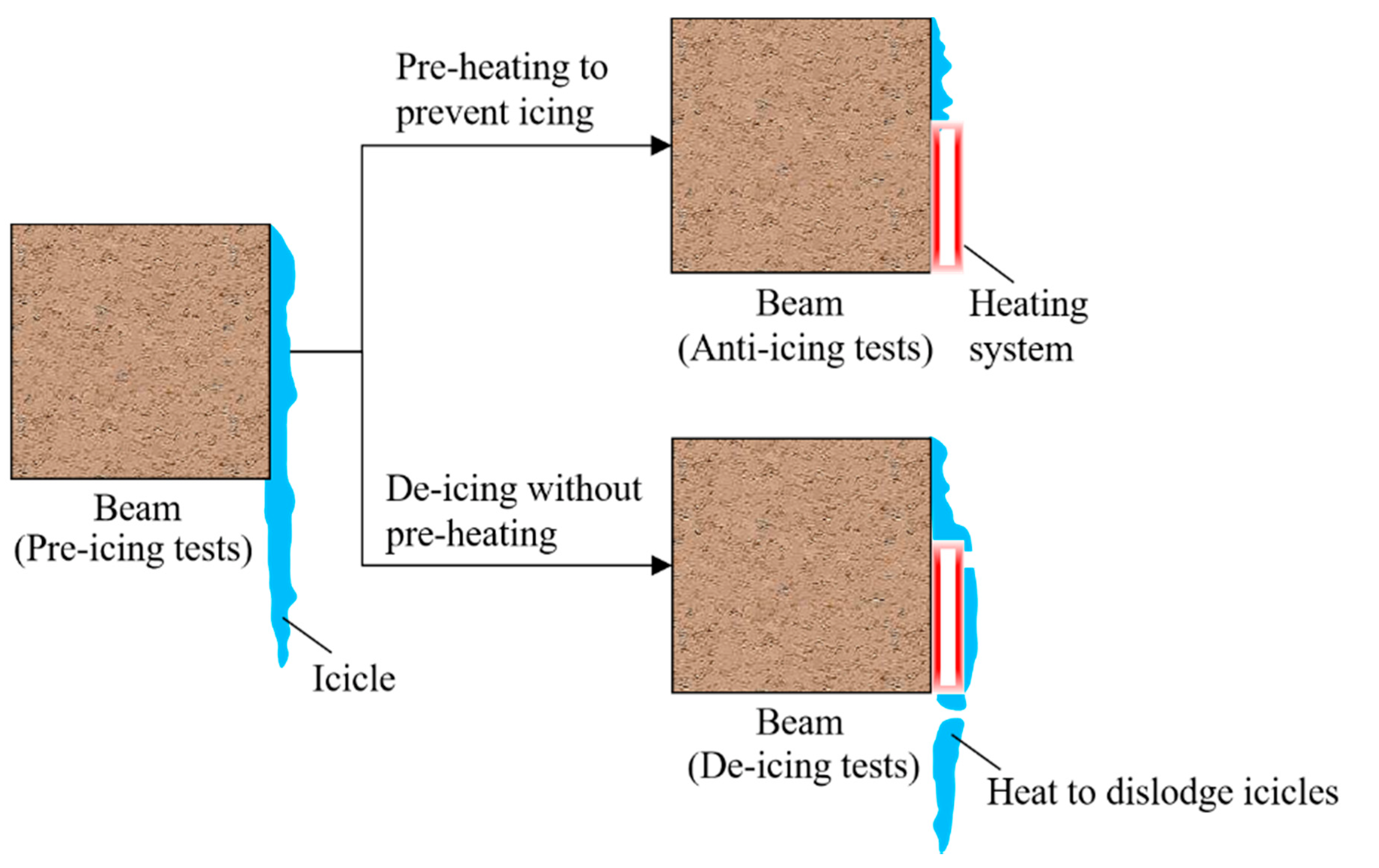
Figure 1. Schematic diagram of the de-icing test idea of the beam.
Applsci 13 03793 g001
Figure 2. Technical route.
Applsci 13 03793 g002
Figure 3. (a) The test system schematic; (b) the working relationships of each system.
Applsci 13 03793 g003aApplsci 13 03793 g003b
Figure 4. The wind direction diagram from the side view.
Applsci 13 03793 g004
Figure 5. (a) The cold chamber; (b) the temperature and humidity recorder; (c) the dimension information of the model beam.
Applsci 13 03793 g005
Figure 6. Diagram for measuring the dimensions of each icicle: (a) length, (b) diameter, and (c) tilt angle.
Applsci 13 03793 g006
Figure 7. (a) Overall view of a single CFHC; (b) the sectional diagram of the CFHC; (c) stainless steel sheet; (d) heat-insulating film; (e) thermocouple wires.
Applsci 13 03793 g007
Figure 8. The internal details and size information of the heating system: the arrangement of the CFHC and thermocouples.
Applsci 13 03793 g008
Figure 9. Icing diagram after 120 min of spraying: (a) −5 °C, (b) −10 °C, (c) −15 °C, (d) −15 °C and 3 m/s, (e) −15 °C and 5 m/s.
Applsci 13 03793 g009aApplsci 13 03793 g009b
Figure 10. The icicle histograms: (a) −5 °C, (b) −10 °C, (c) −15 °C, (d) −15 °C and 3 m/s, (e) −15 °C and 5 m/s.
Applsci 13 03793 g010aApplsci 13 03793 g010b
Figure 11. The icicle size variation with ambient temperature and wind velocity. Note: Lmax is the maximum length; Lave is the average length; Dmax is the maximum diameter; Dave is the average diameter.
Applsci 13 03793 g011
Figure 12. (a) Test process during the no pre-heating anti-icing test; (b) temperature rise rules of the heating system with or without rainfall: A, B, and C represent the three thermocouples and −15 °C is the ambient temperature.
Applsci 13 03793 g012aApplsci 13 03793 g012b
Figure 13. (a) Anti-icing effects under different pre-heating times; (b) variation of temperature at freezing moment with the pre-heating time.
Applsci 13 03793 g013aApplsci 13 03793 g013b
Figure 14. (a) Anti-icing effects under different environments; (b) variation of ice coverage ratio with ambient temperature and wind velocity.
Applsci 13 03793 g014
Figure 15. (a) Anti-icing effects after rearranging the CFHC; (b) temperature rise rule after rearranging the CFHC under the rainfall condition.
Applsci 13 03793 g015
Figure 16. Passive de-icing process without wind.
Applsci 13 03793 g016
Figure 17. Variation of the de-icing time period with the wind velocity.
Applsci 13 03793 g017
Table 1. Performance parameters of the CFHC.
DiameterResistanceLengthPowerThermal
Efficiency
Tensile
Strength
Compressive
Strength
6 mm≈8.5 Ω·m−114 m28 W·m−198.2%40.41 MPa60.75 MPa
Table 2. The test conditions of icing tests.
Group NumberPrecipitation (mm/min)Ambient Temperature (°C)Wind Velocity (m/s)
11−50
21−100
31−150
41−153
51−155
Table 3. The size of the icicle and ice layer under different ambient temperatures.
Test ConditionsLmax/(cm)Lave/(cm)SE of LaveDmax/(mm)Dave/(mm)SE of Laveθ/(°)
−5 °C22.49.590.6214.2313.120.030
−10 °C35.813.581.0315.1413.880.030
−15 °C38.616.020.9418.0515.050.140
−15 °C, 3 m/s65.126.442.8522.3418.410.2320.4
−15 °C, 5 m/s67.129.892.7728.1722.560.4122.7
Note: θ is the tilt angle; SE is the standard error.
Table 4. The test conditions and the ice coverage ratio of icing tests under windy conditions.
Group NumberAmbient Temperature
/(°C)
Wind Velocity
/(m/s)
Pre-Heating Time
/(min)
Precipitation
/(mm/min)
Ice Coverage Ratio
1−534010%
2−1034010%
3−15340128.27%
4−5540128.88%
5−15540192.07%
Table 5. The test conditions and the de-icing time period of passive de-icing tests under windy conditions.
Group
Number
Ambient Temperature
/(°C)
Wind Velocity
/(m/s)
Thickness of the
Ice Layer
/(mm)
De-Icing
Time Period
/(min)
1−150856
2−1511355
3−1521757
4−1531855
5−1541958
6−1552158
Disclaimer/Publisher’s Note: The statements, opinions and data contained in all publications are solely those of the individual author(s) and contributor(s) and not of MDPI and/or the editor(s). MDPI and/or the editor(s) disclaim responsibility for any injury to people or property resulting from any ideas, methods, instructions or products referred to in the content.