Article

Design and Performance Research of a Wearable Airbag for the Human Body

School of Automotive and Traffic Engineering, Jiangsu University, Zhenjiang 212013, China
*
Author to whom correspondence should be addressed.
Appl. Sci. 2023, 13(6), 3628; https://doi.org/10.3390/app13063628
Submission received: 27 January 2023 / Revised: 4 March 2023 / Accepted: 9 March 2023 / Published: 12 March 2023

Abstract

:
In this paper, an integrated wearable airbag is proposed to protect the vulnerable pedestrian during a vehicle–pedestrian collision accident. To evaluate the protection performance of this newly proposed integrated wearable airbag, the airbag inflator finite element model is first verified via an inflator tank test, and the simulated results agree very well with the test. Next, the finite element model of the vehicle–pedestrian model is established, including a simplified vehicle model and a biomechanical HBM with the integrated wearable airbag. The numerical results show the newly proposed wearable airbag can effectively protect the pedestrian by significantly reducing injuries to the head and chest. Since head injury is the most important injury type, a complete set of injury indexes is adopted to evaluate severity of head injury, including HIC15, 3 ms resultant acceleration, and intracranial pressure. To further improve the protection performance of the airbag on the HBM’s head, a parametric study is conducted towards two design parameters of the wearable airbag: inflator gas mass and pulling strap length. The parametric investigation shows 26 g gas and a 20 mm pulling strap can provide the best protection for the HBM’s head.

1. Introduction

According to the World Health Organization, about 1.2 million people die in traffic accidents worldwide every year, and 30% of them are pedestrians [1]. In the past several decades, vehicle passive safety has substantially developed and has been widely adopted in commercial vehicles. The safety of vehicle occupants has been improved significantly. However, there is still a lack of effective passive safety protection methods for pedestrians involved in vehicle–pedestrian collision accidents.
Some scholars have studied the physical behavior of pedestrians after collision with cars. Otte Dietmar counted 762 vehicle–pedestrian collisions [2]. The study found that 60% of all pedestrians suffered head injuries. With an increase in car speed, the collision possibility between the head and the windshield increases. When the speed is higher than 30 km/h, AIS3 grade head injuries will occur. Jikuang Yang [3] reviewed the research on the biomechanics of pedestrian injuries in automobile crashes. The dynamic response of pedestrians in crashes, the injury mechanism, and the damage under different loading conditions are described in detail.
Airbags have been used in automobiles for more than 30 years, and are standard equipment in automobiles. With successful application in automobiles, airbag technology continues to find new applications, such as fall protection for elderly people. Studies shows one-third to one-half of people over 65 years of age experience falls, and half of the elderly who fell before will fall repeatedly [4,5]. Therefore, researchers designed wearable airbags that can detect falls and reduce fall injuries. For example, Toshiyo Tamura et al. [6] designed a set of experiments to simulate falls, analyzed and compared the acceleration changes at the moment of fall for 16 experimental subjects, and developed an algorithm capable of detecting falls 300 ms in advance. In addition, they designed a jacket that protects the head and hips when a person falls by an automatically inflated airbag. The inflated airbag can effectively absorb the impact energy of the fall and reduce the damage to the human body [4]. Meanwhile, airbag products for wearing have been put into the market. Wolk has developed a hip airbag [7]. The central computer of the airbag analyzes the direction and acceleration data, and automatically detects whether there is a fall. When a person falls, the inflator inflates carbon dioxide into the left or right airbag. The Wolk airbag has undergone extensive safety tests, and the inflation time is within 100 ms. In the Chinese market, there is a new product, the S-airbag, which can protect the head, back, and hips of the human body and prevent false triggering by recognizing 12 postures such as bending and sitting through AI chips with high computational power.
Wearable airbags have also been utilized to protect bicycle and motorcycle riders. Unlike hip injuries due to falls, head and chest injuries occur most frequently and cause the highest fatality rates during the accidents [8,9,10]. The Italian brand Dainese has incorporated the concept of airbags into specific garments worn by motorcycle riders and designed a new product, D-AIR, which is capable of significantly reducing the impact forces on the rider in an accident event [11]. Mehmet Kurt et al. [12] proposed an inflatable airbag helmet for bicycle riders. This inflatable airbag helmet can provide better protection than the traditional EPS helmet and can effectively reduce the risk of head and brain injury. Jeong et al. [13,14] utilized three acceleration axes and three angular velocity axis sensors to obtain real-time bicyclist motion state, which is used to distinguish whether an accident occurred. In the numerical research of airbags, Massaro et al. [15] established the finite element model of an airbag, verified the airbag model through a chest impact test, and analyzed the impact of inflation pressure and airbag thickness on airbag performance. Girardi [16] established the finite element model of a wearable airbag, and connected it to the dummy. Thorax and shoulder impact tests were carried out, respectively, and the best inflation pressure was found.
Regarding wearable airbag protection for the human body, currently there is a lack of effective wearable airbag devices for pedestrians in a vehicle–pedestrian accident. In this paper, an integrated wearable airbag is proposed to protect pedestrians, who are vulnerable during an accident. The device combines an inflatable helmet and an inflatable jacket and includes airbags for the head, neck, chest, and hips. Its finite element model is established in Hypermesh and analyzed via Radioss solver to evaluate the protection effects of the wearable airbag. Finally, two parameters, airbag inflation mass and head airbag pull strap length, are selected for analysis to improve the protection effect of airbags.
The work is organized as follows. In Section 2, a wearable airbag for pedestrian protection is proposed, and its structural components, design concept, and working principle are introduced. In Section 3, the airbag inflator is modeled, and its effectiveness is verified. Then, a finite element model of vehicle–pedestrian collision is created. In the fourth section, the two collision simulations with and without the wearable airbag on the HBM are conducted. The injuries of two dummies are compared, and the deformation and protection mechanism of the wearable airbag are examined. In the last section, effects of the inflation gas mass and the length of head airbag strap on airbag protection performance are analyzed, and the best matching scheme of these two parameters is obtained.

2. Design of a Wearable Airbag System

A wearable airbag which combines an airbag jacket and an airbag helmet is proposed, and its protection area, sensors, inflators, and working principle are introduced.

2.1. Components of a Wearable Airbag System

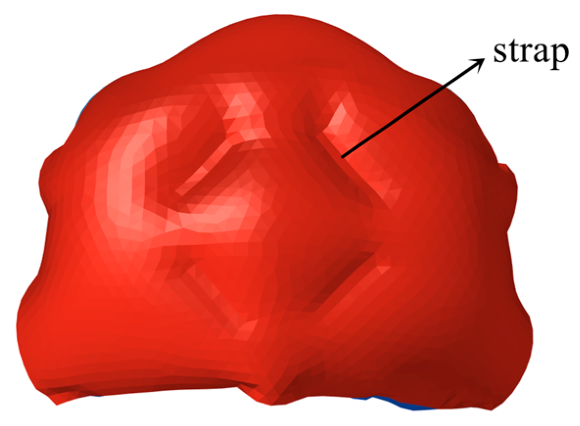
A wearable airbag system mainly includes power supply and a control unit, collision sensing device, inflator, and airbag woven bags. During a vehicle–pedestrian crash event, injury-prone areas include the head, neck, back, chest, and hips. The principle to provide adequate protection for a pedestrian is to design a wearable airbag system that covers as much of the above injury-prone areas as possible. In particular, head injury is the most critical injury type that causes fatality. Regarding head protection, two inflatable columns, as shown in Figure 1, are used to protect both sides of the head, and they also protect the head’s top area, forehead, neck, and collarbone. The back of the head is protected by an integral airbag. Inside the airbag, at the back of the head, four pulling straps are installed to maintain its inflated shape, which can match the shape of back of the head and provide support for the back of the head, as shown in Figure 2. The length of the straps can be adjusted, so the inflation thickness, that is, the distance between the front and rear surfaces of the airbag, can also be adjusted.

2.2. Airbag Sensing System

The airbag in the vehicle is triggered by the acceleration sensor installed on the vehicle body. When the deceleration in the impact direction reaches the set value, the airbag will be triggered. This sensor is not suitable for wearable airbags. It needs to be accurately determined whether the human body collides or falls. The six-axis gyroscope is selected, which can obtain acceleration and angular acceleration in three directions. From the moment of vehicle–pedestrian contact, the sensor device of the wearable airbag system would finish the signal collection and analysis process within 30 ms. When both acceleration and angular acceleration exceed the set threshold, the signal will be transmitted to the electronic control unit (ECU) to trigger the inflator, and the airbag inflation will complete within 50 ms.

2.3. Airbag Inflator

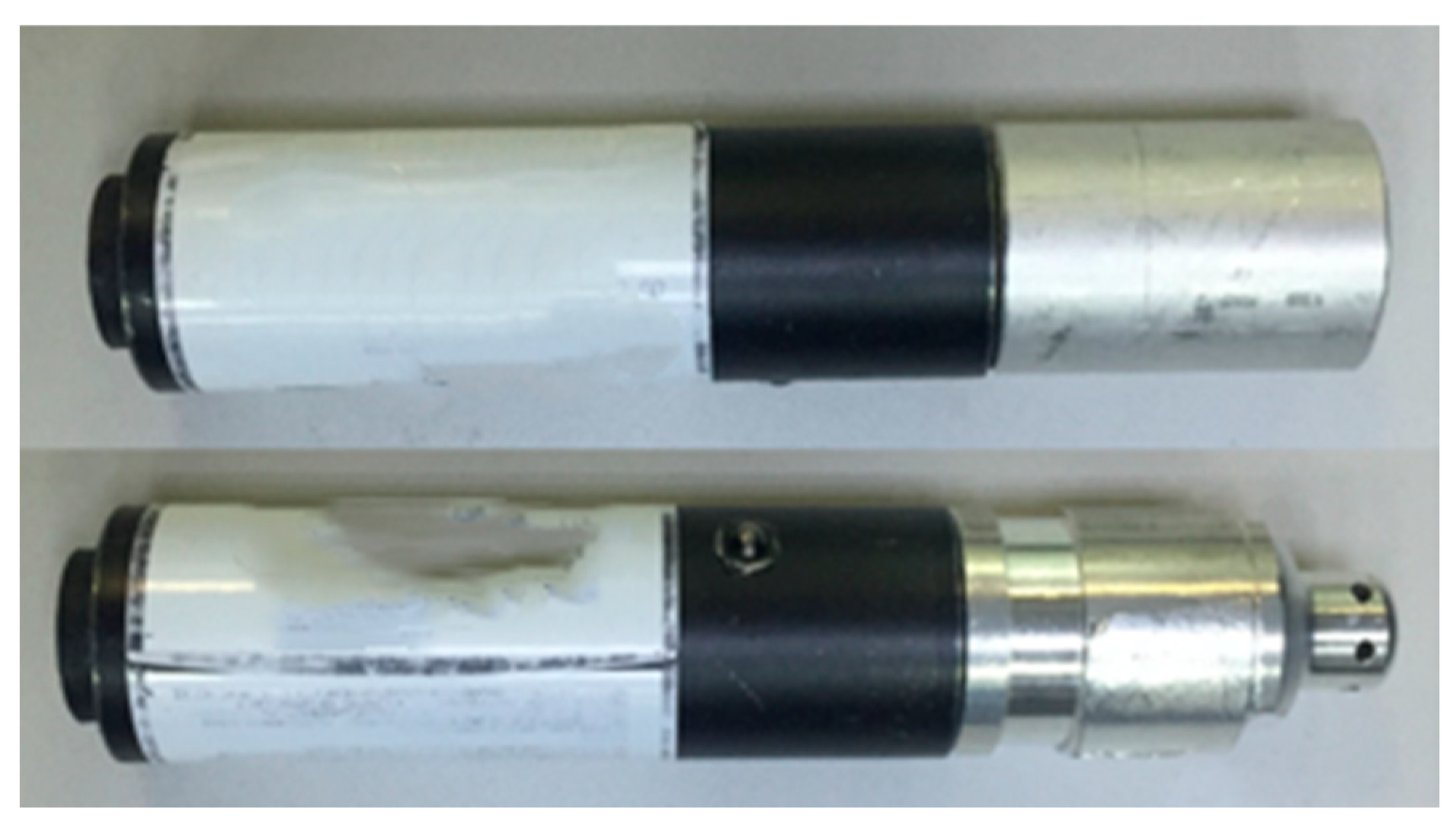
The choice of an inflator plays an important role in determining the protection performance of an airbag [17]. The most common inflators include compressed, pyrotechnic, and hybrid inflators. The compressed inflator only produces a limited amount of gas. In contrast, a pyrotechnic inflator can produce a large amount of gas, and is widely utilized in automobiles [18]. During the airbag inflation process, the combustion of gunpowder produces a large amount of gas, and high-temperature flames are also produced [19]. The third type of inflator is the hybrid inflator, which can produce a large amount of gas and maintain a small dimension. This type of inflator uses the pressurization effect induced by a small amount of burning gunpowder to break through the bursting diaphragm in the inflator. Then, the heated compressed gas is discharged from the pressure relief hole and fills the airbag [20,21]. The wearable airbag requires a gas generator which is small and able to generate a large volume of gas. Therefore, the compressed inflator cannot meet the requirements. In addition, the airbag of the wearable airbag system is very close to the human body, so the high-temperature flames produced in the pyrotechnic inflator need to be avoided. Therefore, the ACH 27 hybrid inflator, as shown in Figure 3, is selected, and the helium–argon mixture of compressed gas stored in this inflator is also harmless to human body.

2.4. Working Principle of Wearable Airbag

When the pedestrian wearing the airbag moves, the six-axis gyroscope constantly detects and updates the relevant acceleration changes and transmits the detected acceleration data to the ECU. In the process of collision, the ECU analyzes the data collected by the acceleration sensor and sends out a trigger signal to the inflator once the preset collision fall algorithm is met. Then, the inflator will release the compressed gas in a short period of time. During the whole collision process, the wearable airbag provides cushioning between the pedestrian and the vehicle, and reduces the injury to the wearer.

3. Vehicle–Pedestrian Collision Finite Element Model

The vehicle–pedestrian collision finite element model is created in Hypermesh and is analyzed in the well-known explicit solver, Radioss. The collision finite element model includes a vehicle model and HBM model with a wearable airbag. The airbag inflator determines the pressure of an airbag and plays a critical role for safety protection of the pedestrian. Therefore, the inflator model is first created in Radioss and validated via the experimental data. After that, the airbag finite element model is created and matched with the outline of the pedestrian HBM model, and finally the vehicle–pedestrian collision model is completed.

3.1. Validation of the Airbag Inflator Finite Element Model

This paper uses the Uniform Pressure Method [22,23] to simulate the inflation of an airbag. The pressure inside the airbag is assumed to be uniformly distributed during the inflation process and the gas filling the airbag is simulated by defining the mass and temperature of the gas. It is worth noting that the gas charged to the airbag in the uniform pressure method is an ideal gas with a constant specific heat capacity. Simulating the filling process using the uniform pressure method has the advantages of easy model control and fast calculation. Equation (1) shows the formula to calculate the airbag volume [24]. In terms of divergence theorem, the volume integration can be transformed to surface integration. The surface integration at each time step can be obtained by integrating the surface area of the elements.
V = d x d y d z = x n x d Γ i = 1 N x i ¯ n i x A i
where dxdydz is the volume of the element in the integration, Γ is the surface area of the element in the integration, V is the volume of the airbag, and x i ¯ is average value of element coordinates on the x-axis. nix is the cosine of the angle between the element normal direction and the x-axis, and Ai is the surface area of the ith element. The uniform pressure method simulates the unfolding process of an airbag in which the volume of the airbag gradually increases under the reaction induced by pressure, temperature, and mass. The airbag inflation process is adiabatic, the specific heat capacity of the gas is constant, the pressure and temperature inside the airbag are uniform, and the pressure and volume of the uniform pressure method airbag model satisfy the following equations:
p V = m R T
p = ( γ 1 ) ρ E
γ = C P C v
where p is the gas pressure in the airbag, m is the gas mass in the airbag, R is the molar gas constant, T is the air temperature inside the airbag, and γ is the ratio of constant volume specific heat to constant pressure specific heat of the gas, ρ is the gas density, and E is the specific internal energy of the gas.
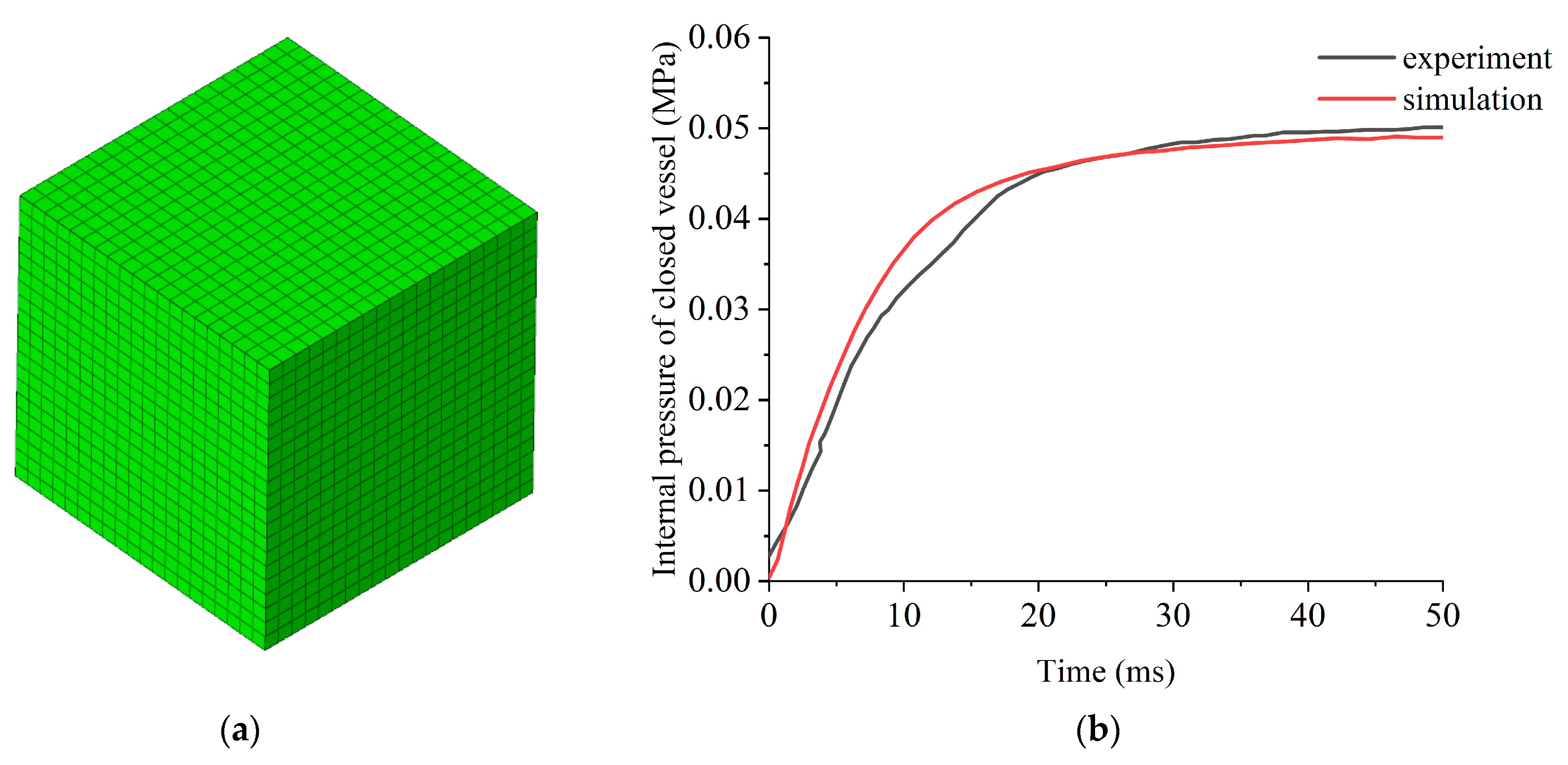
In this study, a tank test is conducted to validate the effectiveness of the uniform pressure method utilized in the finite element simulation and to obtain the input curves that characterize the injected gas utilized in the finite element model. These two curves include the temperature variation curve and the gas mass curve. These two curves are assigned to the keyword /PROP/INJECT1 in Radioss. In the tank test, the gas inflator is placed in the closed container, and then detonated. The total mass of the gas is 12 g, the initial temperature is a constant value, 295 K, and the volume of the closed vessel is 28.3 L. The molar mass of the gas is 0.031 kg/mol, and the specific heat capacity at constant pressure is 520 J/(kg·K). The temperature history curve, in Figure 4a, and the internal pressure history curve, in Figure 5b, are recorded by the temperature sensor and pressure sensor, respectively. The time history curve of gas mass, in Figure 4b, is derived via MTA analysis [25,26] in terms of the above recorded temperature history curve and internal pressure history curve. The FEA model of the tank test is shown in Figure 5a and it contain 62,100 shell elements. Rigid material is assigned to the shell elements. As shown in Figure 5b, the internal pressure history curves obtained by simulation and testing have excellent agreement.

3.2. Finite Element Model of Vehicle–Pedestrian Collision

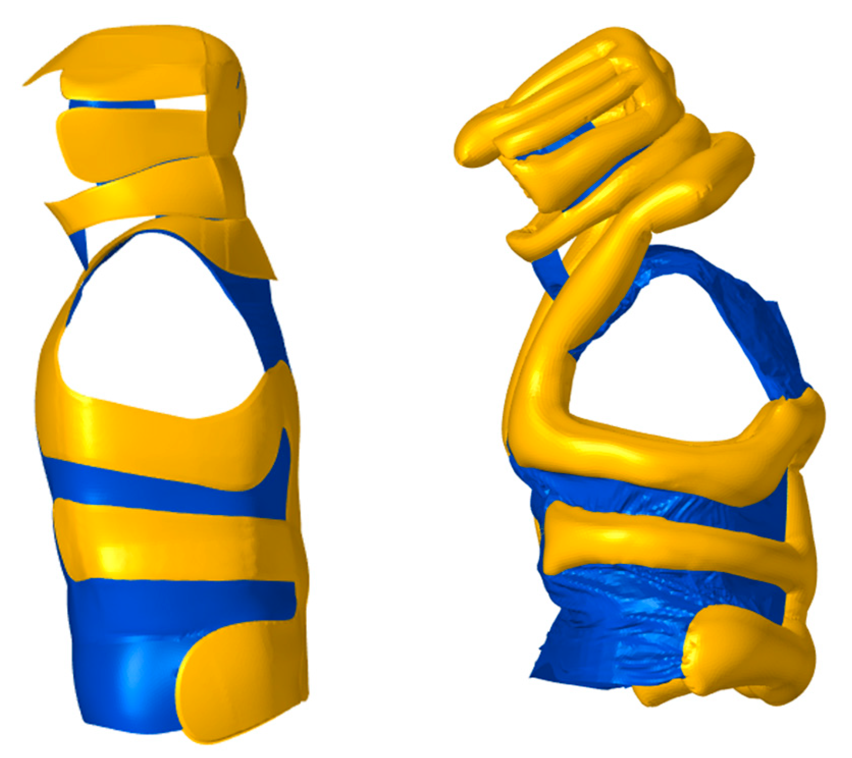
The finite element model of vehicle–pedestrian collision includes an HBM model, the wearable airbag system model, and the vehicle model. Figure 6 shows the front and back sides of the wearable airbag system. The yellow part is the airbag column, and the blue part is the fabric connecting various parts of the airbag. Figure 7 shows the wearable airbag systems before and after inflation, respectively. The inflatable part of the airbag finite element model contains 93,700 shell elements.
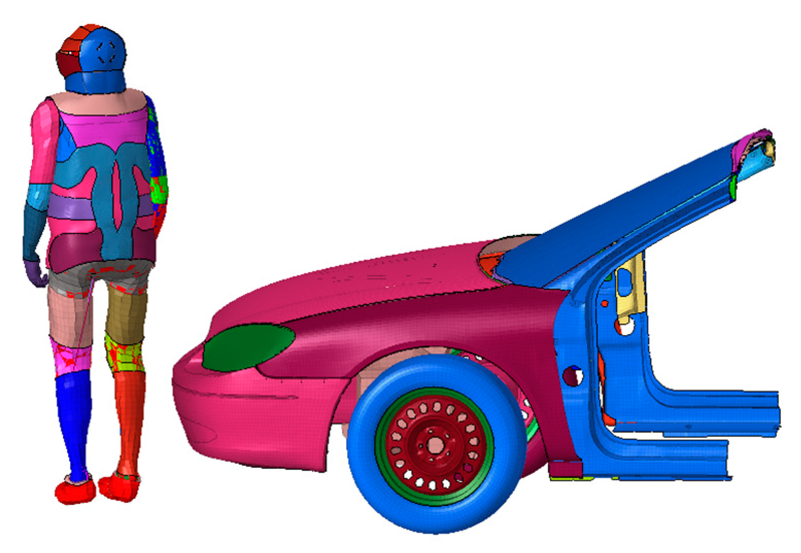
The finite element model of Ford Taurus is used, which was released and verified by the National Highway Traffic Safety Administration (NHTSA) [27]. To improve the modeling efficiency, a simplified vehicle model is adopted based on the finite element model of Ford Taurus. The front bumper, front windshield, hood, A-pillar, and other parts that the pedestrian can contact during the collision are retained. All other components are not considered. The mass of those neglected parts of the vehicle is attached to the retained vehicle body. In current study, an HBM from Altair’s HUMOS 2 series is used. To make the study relevant to most pedestrians of all heights, a 50th-percentile HBM was selected for the design of a wearable airbag system. Contacts are defined between all vehicle parts, and between the vehicle and the HBM with the wearable airbag system. The vehicle-pedestrian collision model is shown in Figure 8.

4. Analysis of Wearable Airbag Protection Performance

4.1. Pedestrian Motion Posture during the Collision Process

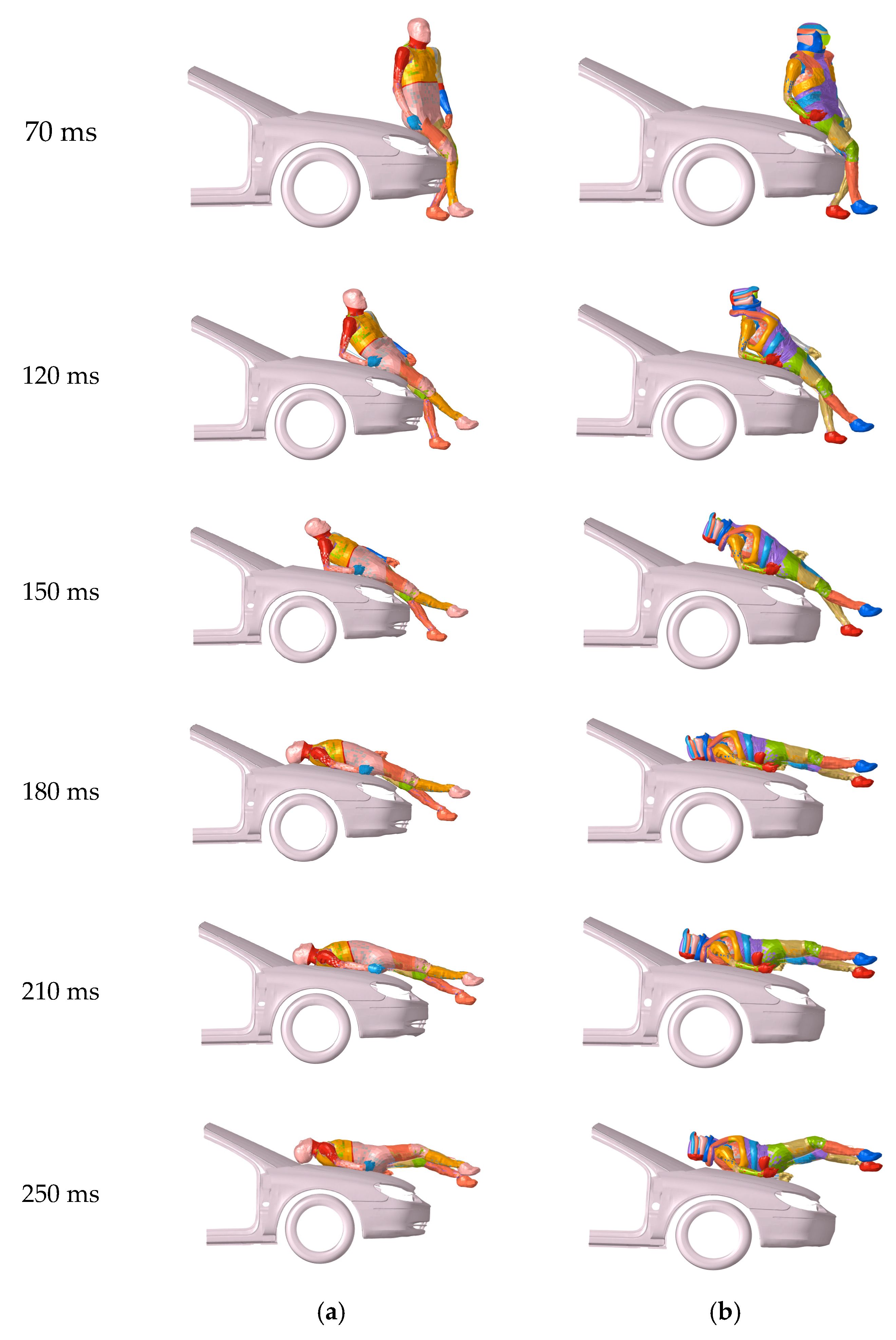
The collision speed of the vehicle is 30 km/h and the collision time is 250 ms. Figure 9 shows the pedestrian motion posture at different collision times.
At 70 ms, the lower legs and knee joints of the HBM are in contact with the front bumper of the vehicle. At 120 ms, the thighs and hips of the pedestrian collide with the edge of the hood. At 150 ms, the HBM’s back falls to the hood and the body is completely suspended. At 180 ms, the HBM’s back fully fitted the hood, and the head hit the edge of the hood and the lower edge of the windshield. After 180 ms, the head and back of the HBM bounced upward due to the reaction force of the hood.

4.2. Protective Performance of Wearable Airbag

When pedestrians are involved in a collision with a car, severe head injury is a major cause of death [28]. A widely utilized head injury criterion is HIC, which is calculated by integrating the acceleration of the head during a given time. In this paper, HIC15 is chosen as the head injury metric. According to the protection of vulnerable road users (VRU) in the European New Car Assessment Program (E-NCAP), HIC15 is used as a pedestrian head injury indicator which should be less than 1000.
H I C 15 = max { [ 1 t 2 t 1 t 1 t 2 a ( t ) d t ] 2.5 ( t 2 t 1 ) }
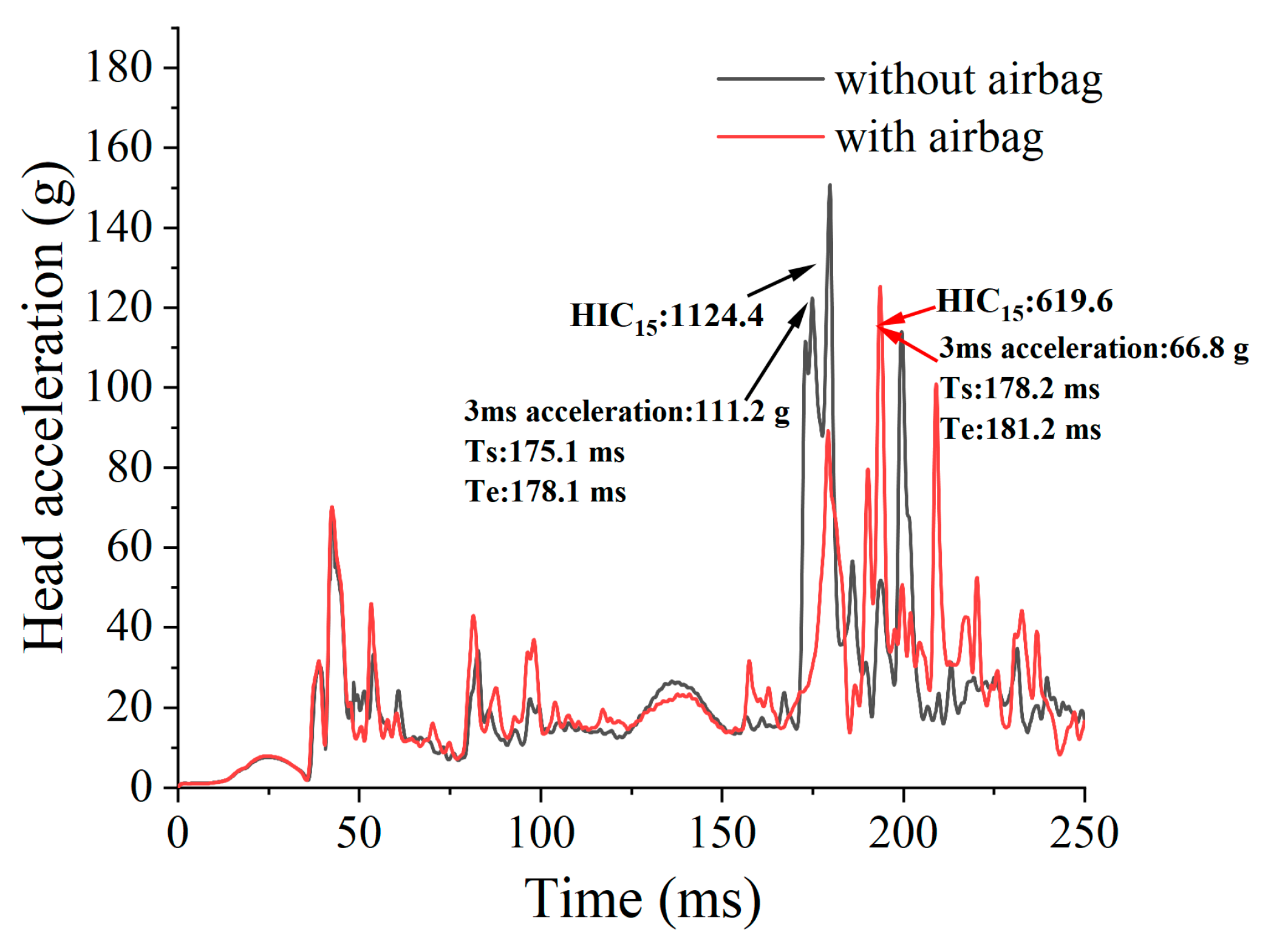
where a(t) is the resultant acceleration of the head, and the time interval between t2 and t1 is 15 ms. The head accelerations of the HBM in the two scenarios with and without airbag are extracted and filtered, respectively.
When the lower leg of the pedestrian contacts with the bumper, the impact of the vehicle causes a high acceleration of the lower limb of the HBM. After the whole human body rotates, the head hits the engine hood, which causes serious injury. Figure 10 shows the acceleration curve of the lower leg of the pedestrian when impacted. As shown in Figure 11, the HIC15 value of the HBM without the airbag is 1124.4, while the HIC15 of the HBM with the airbag is 619.6. That is a 45.9% decrease in the HIC15 of the HBM’s head. In addition, another indicator of head injury is 3 ms acceleration, which refers to the maximum acceleration of the head that can last for 3 ms. According to the European New Car Assessment Program (ENCAP), when a head acceleration of 88 g or more can last for 3 ms, it can lead to serious head injury. The 3 ms resultant head acceleration of the HBM wearing the airbag also decreased from 111.2 g to 66.8 g.
In 1980, Ward [29] proposed the injury limit of intracranial pressure based on studies of animal and human cadaveric experiments, and finite element brain models. Severe injury occurs when the peak intracranial pressure exceeds 235 kPa, moderate injury occurs when the peak is between 173 and 235 kPa, and very mild or no injury is caused when the peak pressure is below 173 kPa. Figure 12a,b illustrates the peak intracranial pressure of the HBM without the deployment of the wearable airbag system at 174 ms and the peak intracranial pressure of the HBM with the deployment of the wearable airbag system at 179 ms, respectively. The peak intracranial pressure of the HBM without the deployment of the wearable airbag system is 261.5 kPa and the pedestrian will be severely injured according to Ward’s injury criteria. In contrast, the peak intracranial pressure of the HBM wearing airbags is 168.6 kPa, a 35.5% decrease in peak pressure, and the pedestrian would not be injured or just injured mildly. Therefore, the wearable airbag system can provide significant protection for the pedestrian’s head.
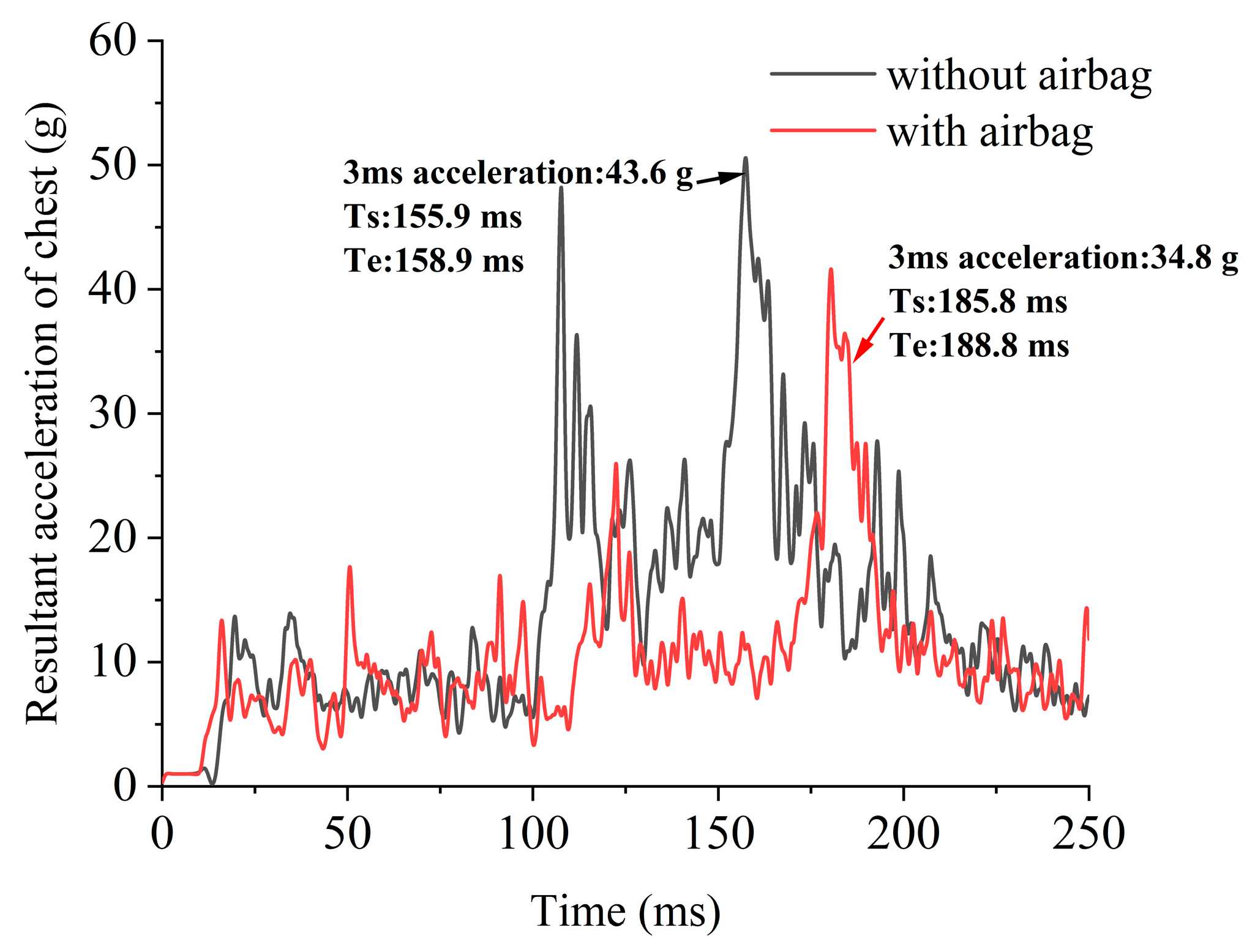
Regarding the chest protection performance of the wearable airbag system, the 3 ms resultant acceleration of the chest is specified as the injury indicator of the chest. Figure 13 shows the resultant acceleration curves of the chest of the HBM in both scenarios, with and without the deployment of the wearable airbag system. The value of 3 ms resultant acceleration of the pedestrian’s chest is 43.6 g for the HBM without the deployment of the wearable airbag system and 34.8 g for the HBM with the deployment of the wearable airbag system, a 20.2% drop. The injury indexes for the head and chest are summarized in Table 1, and we can immediately see the effectiveness of the wearable airbag system in protecting the pedestrian’s head and chest.

5. Parameter Analysis of Wearable Airbag

The gas mass of the inflator and length of the pulling strap are two important design parameters for the wearable airbag system. The change in the gas mass directly affects the pressure inside the airbag, which determines the stiffness of the airbag. If the pressure is too large, the airbag will be too rigid, and this will not provide good protection of the human body. If the pressure is too small, the airbag will be too soft, and the airbag has a risk of being smashed through. In addition to the importance of choosing the right gas mass, the thickness of the airbag inflation also significantly influences the protective performance of the airbag. The thickness of the deployed airbag at the back of the head is decided by the length of four pulling straps, as shown in Figure 14. When the airbag is inflated, the pulling straps are gradually stretched out and the strap length controls the final thickness of the inflated airbag. HIC15 of the head injury index is chosen to evaluate the protection effectiveness of different gas masses and strap lengths, as well as their combinations.
In the original design of the wearable airbag system, the gas mass is 24 g and the length of pulling straps are 5 mm. Here, 20 g, 22 g, 24 g, 26 g, and 28 g are selected as the five levels of gas mass, and 5 mm, 10 mm, and 20 mm are specified as the length of pulling straps. Figure 15a shows the gas pressure with different gas masses, with a fixed pulling strep length of 5 mm. As expected, when the gas mass increases, the airbag pressure also increases. Figure 15b shows the inflation thickness of the head airbag at different strap lengths, with a fixed gas mass of 24 g. The central thickness of the head airbag increases with the increase in the pulling strap length.
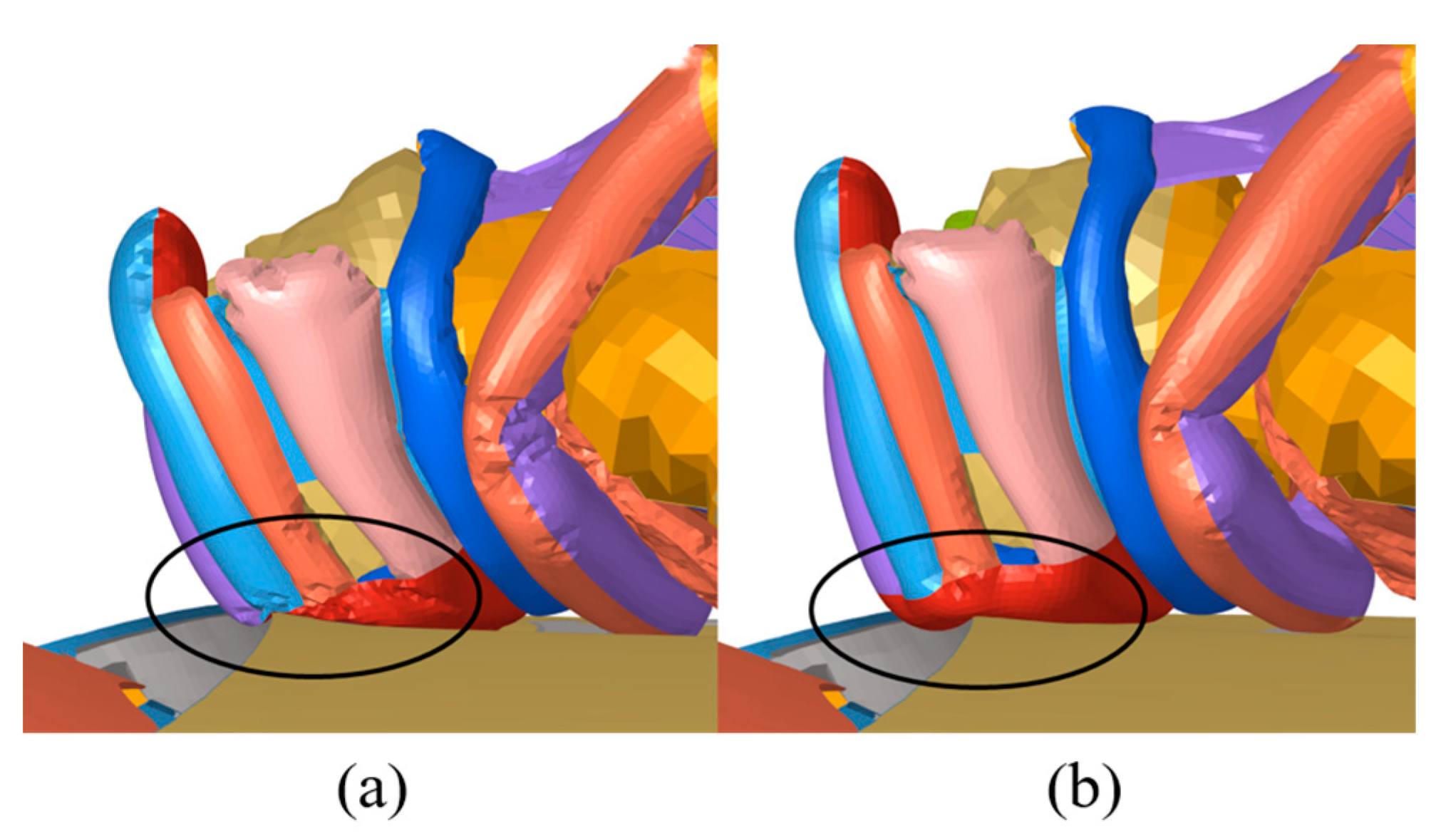
Figure 16 shows the HIC15 head injury index distribution under different combinations of gas mass and pulling strap length. For a given gas mass, HIC15 decreases with an increase in the pulling strap length between 5 mm and 20 mm. With an increase in gas mass, the head injury index HIC15 decreases first and reaches a minimal value between 24 g and 26 g. HIC15 begins to increase after the gas mass is more than 28 g. It is found that, when the gas pressure of the airbag is not high enough, the upper and lower surfaces of the airbag are smashed through and the HBM’s head hits directly on the hood, as illustrated in Figure 17a. If the gas pressure is sufficient, the inflated airbag maintains a good shape and prevents direct contact between the HBM’s head and the vehicle hood, as illustrated in Figure 17b. However, when the gas mass rises to 28 g, the pressure inside the airbag is close to 200 kPa, which significantly increases the rigidity and weakens the airbag’s protection effect. Furthermore, the gas mass 26 g and the pulling strap length, 20 mm provide the best protection performance for the HBM’s head, and can protect the pedestrian from head injury.

6. Discussion

In this study, a pedestrian–vehicle FEA model has been established, and a wearable airbag is used to protect pedestrians in the accident, which is rare in previous studies. The protective performance of the wearable airbag is evaluated, demonstrating that the wearable airbag can reduce the injury of pedestrians in the collision.
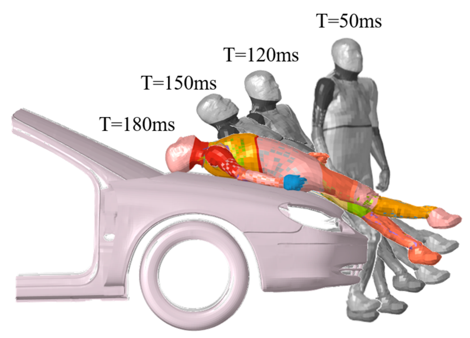
Figure 9 and Figure 18 show the motion posture of the HBM at an impact speed of 30 km/h. At 50 ms, the HBM’s thigh collides with the edge of the hood. During the collision, the lower leg gradually detaches from the bumper with a bending action, and the head collides with the edge of the hood and windshield at 180 ms. The posture of the pedestrian during collision agrees well with the results of Teng’s study [30]. However, the difference is that the vehicle impact speed was 40 km/h and the pedestrian’s head hit the windshield in their study. Apparently, the different impact speeds resulted in different head impact positions, as confirmed by Otte [2]. With an increase in car speed, the collision possibility between the head and the windshield increases.
In recent studies, wearable airbags have been used to prevent falls after stroke [31], to protect elderly people with broken hips [7,32], and to protect cyclists and motorcycle riders [12,15], but they are rarely used to protect pedestrians in collision. This study combines inflatable helmets, vests, and hip airbags to protect pedestrians from collision in all directions. The finite element simulations carried out in this study confirm that a wearable airbag can reduce the injury of pedestrians, as shown in Table 1. Some studies [15,16] have shown that inflation pressure and airbag thickness play a decisive role in the protection performance of wearable airbags. They have demonstrated that a larger airbag deployment thickness is always beneficial, and an optimal inflation pressure that minimizes chest deflection can be found. These findings are consistent with our research showing that the maximum airbag inflation thickness provides the best protection, but the maximum inflation mass is not favorable because high inflation pressure increases rigidity and weakens the airbag’s protection effect. These results have important implications for the selection of the appropriate inflator and the optimal structure of the wearable airbag.
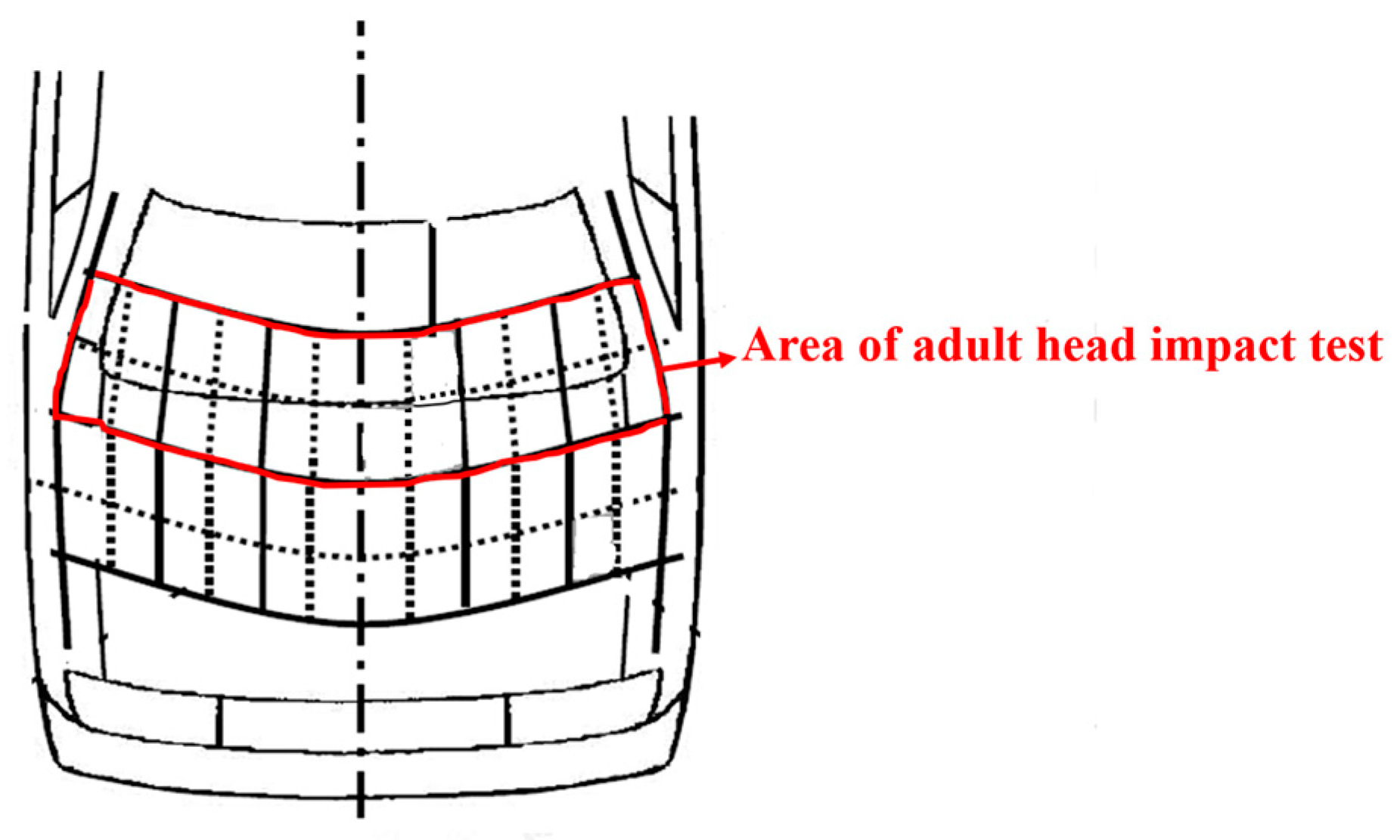
According to the protection of vulnerable road users (VRU) in the European New Car Assessment Program (E-NCAP), the hood and windshield are divided into 24 areas for adult head impact tests, as shown in Figure 19. Correspondingly, we will conduct multiple crash simulations to study the protective effect of the airbag when the head hits in different positions. Crash simulations at different speeds will also be carried out to evaluate the airbag’s protective performance at higher impact speeds in our future work.
The current research is focused on evaluating the protective performance of wearable airbags using numerical models. In other studies, wearable airbags were evaluated by conducting a drop test [15,33]. Therefore, the newly designed wearable airbag should be manufactured and tested for further calibration of the numerical model of the airbag, such as the characteristics of the airbag material. In addition, gyroscopes are crucial in the practical application of wearable airbags, but the signal collection and process of the gyroscope is out of scope of current study. These issues will be addressed in future work.

7. Conclusions

In this paper, a wearable airbag system for pedestrians in a vehicle–pedestrian accident is proposed. Based on the verified gas inflator model, the finite element models of the wearable airbag systems and vehicle–pedestrian collision are established. The collision simulation is carried out, and the protection performance of the designed wearable airbag is evaluated. The main conclusions are summarized as follows:
(1)
An integrated wearable airbag, which combines an inflation helmet and jacket is proposed to protect the safety of pedestrians during a vehicle–pedestrian collision. The gas mass of the inflator and the length of the pulling straps are the design parameters to improve the protection effectiveness.
(2)
The finite element model of the airbag inflator is first verified via an inflator pressure-tight vessel test. Then, the finite element model of vehicle–pedestrian collision is constructed to evaluate the protection performance of the newly proposed wearable airbag. The proposed wearable airbag shows an effective protection towards the HBM’s head and chest. In particular, the protection effectiveness of the head is examined via HIC15, 3 ms resultant acceleration, and the intracranial pressure.
(3)
The parametric study of the gas mass and the pulling strap length shows that 26 g gas and 20 mm pulling strap length provide the best protection for the HBM’s head. If the gas mass is below 20 g, the head will smash through the airbag and hit directly on the vehicle hood. If the gas mass is too big, the airbag pressure will rigidize the airbag and weaken the protection effectiveness of the airbag.

Author Contributions

Conceptualization, W.T.; Methodology, X.Z.; Software, Z.X.; Validation, Z.X.; Formal analysis, X.Z. and Z.X.; Investigation, W.T.; Data curation, X.Z. and Z.X.; Writing—original draft, X.Z.; Writing—review & editing, W.T.; Supervision, W.T. All authors have read and agreed to the published version of the manuscript.

Funding

X. Zhang acknowledges the support of Goodbaby International Holdings Limited for test data. X. Zhang also acknowledges funding support of 2021 Jiangsu High-value Patent Cultivation Program (upgrade category) (8411123002) and Goodbaby International (8421123004). W. Tu acknowledges the support of Jiangsu University Faculty Startup Fund (5501120014) and Jiangsu Shuangchuang Doctor Program (1711120022).

Data Availability Statement

The data used to support the findings of this research are included within the article.

Conflicts of Interest

The authors declare no conflict of interest.

References

  1. World Health Organization. Road Traffic Injuries. Available online: https://www.who.int/news-room/fact-sheets/detail/road-traffic-injuries (accessed on 14 July 2019).
  2. Otte, D. Severity and mechanism of head impacts in car to pedestrian accidents. Proc. IRCOBI 1999, 27, 329–341. [Google Scholar]
  3. Yang, J. Review of Injury Biomechanics in Car-Pedestrian Collisions. Int. J. Veh. Saf. 2005, 1, 100–107. [Google Scholar] [CrossRef]
  4. Tamura, T.; Yoshimura, T.; Sekine, M.; Uchida, M.; Tanaka, O. A Wearable Airbag to Prevent Fall Injuries. IEEE Trans. Inf. Technol. Biomed. 2009, 13, 910–914. [Google Scholar] [CrossRef] [PubMed]
  5. Sivaranjani, T.; DhiviyaLakshmi, L.; Yogaaravinth, R.; Srivishnu, J.; Sri Karthick, M.M.; Praveenkumar, A. Fall assessment and its injury prevention using a wearable airbag technology. In Proceedings of the IEEE International Conference on Power, Control, Signals and Instrumentation Engineering, Chennai, India, 21–22 September 2017. [Google Scholar]
  6. Tamura, T.; Yoshimura, T.; Sekine, M. A preliminary study to demonstrate the use of an air bag device to prevent fall-related injuries. Annu. Int. Conf. IEEE Eng. Med. Biol. Soc. 2007, 2007, 3833–3835. [Google Scholar] [PubMed]
  7. Nemeth, B.; van der Kaaij, M.; Nelissen, R.; van Wijnen, J.K.; Drost, K.; Blauw, G.J. Prevention of hip fractures in older adults residing in long-term care facilities with a hip airbag: A retrospective pilot study. BMC Geriatr. 2022, 22, 547. [Google Scholar] [CrossRef]
  8. Mats, U.; Ulf, B.; Kjell, N.; Eriksson, A. Pedal Cycling Fatalities in Northern Sweden. Int. J. Epidemiol. 1993, 22, 483–488. [Google Scholar]
  9. Kong, C.; Yang, J.; Otte, D. A Study of Bicyclist Accidents in Changsha of China and Hannover of Germany. In Proceedings of the International Technical Conference on the Enhanced Safety of Vehicles, Stuttgart, Germany, 15–18 June 2009. [Google Scholar]
  10. Thompson, D.C.; Rivara, F.; Thompson, R. Helmets for preventing head and facial injuries in bicyclists. Nurs. Times 1999, 97, 41. [Google Scholar] [CrossRef] [PubMed]
  11. Azzolin, A.; Dainese, L.; Zanotto, S. Helmet and Process for Manufacturing such a Helmet. Italy WO2016IB50270, 20 January 2016. [Google Scholar]
  12. Kurt, M.; Laksari, K.; Kuo, C.; Grant, G.; Camarillo, D. Modeling and Optimization of Airbag Helmets for Preventing Head Injuries in Bicycling. Ann. Biomed. Eng. 2017, 45, 1148–1160. [Google Scholar] [CrossRef] [PubMed]
  13. Woo, J.; Jo, S.-H.; Byun, G.-S.; Kwon, B.-S.; Jeong, J.-H. Wearable Airbag System for Real-Time Bicycle Rider Accident Recognition by Orthogonal Convolutional Neural Network (O-CNN) Model. Electronics 2021, 10, 1423. [Google Scholar] [CrossRef]
  14. Jo, S.-H.; Woo, J.; Byun, G.-S.; Kwon, B.-S.; Jeong, J.-H. A Study on the Application of LSTM to Judge Bike Accidents for Inflating Wearable Airbags. Sensors 2021, 21, 6541. [Google Scholar] [CrossRef] [PubMed]
  15. Marconi, E.; Gatto, F.; Massaro, M. Investigation on Wearable Airbags for Motorcyclists through Simulations and Experimental Tests. In Transactions on Engineering Technologies: World Congress on Engineering; Springer: Singapore, 2019; pp. 87–100. [Google Scholar]
  16. Girardi, D.; Marconi, E.; Massaro, M. Assessment of Shoulder and Chest Protection of Wearable Motorcycle Airbags. In Proceedings of the International Design Engineering Technical Conferences and Computers and Information in Engineering Conference, Anaheim, CA, USA, 18–21 August 2019; American Society of Mechanical Engineers: New York, NY, USA, 2019; Volume 59216, p. V003T01A026. [Google Scholar]
  17. Alcala, E.; Martinez, L.; Rodriguez, C.J.; López, A.; Neira, F. Analytical Matlab/Simulink model of pyrotechnical gas generators for airbags. Int. J. Crashworthiness 2009, 14, 641–657. [Google Scholar] [CrossRef]
  18. Cheng, C.; Zhang, X.B.; Wang, C.; Wang, L. Numerical investigation on cooling performance of filter in a pyrotechnic gas generator. Def. Technol. 2021, 17, 9. [Google Scholar] [CrossRef]
  19. Liao, T.; Wang, W.; Cao, Y.; Zhao, H.; Cui, T.; Yu, H. Comparative study of pyrotechnic and hybrid side airbags on a certain vehicle type. In Proceedings of the 19th Asia Pacific Automotive Engineering Annual Conference and 2017 Chinese Automotive Engineering Annual Conference, Shanghai, China, 24–26 October 2017. [Google Scholar]
  20. Smith, B.W. Hybrid Inflator with Diffuser End Translating Initiator Boss. U.S. Patent US5890735, 6 April 1999. [Google Scholar]
  21. Hamilton, B.K.; Baglini, J.L. Hybrid Inflator and Related Propellants. U.S. Patent US5627337, 6 May 1997. [Google Scholar]
  22. Wang, X. Research on Airbag Deployment and Its Interaction with Environment Computational Techniques. Ph.D. Thesis, Dalian University of Technology, Dalian, China, 2015. [Google Scholar]
  23. Slaats, P.M.; Pitonyak, A.J.; Wipasuramonton, P.; Hunter, T.; Rains, M.; Wang, D.; Williams, C.; Miller, C. Alternative Airbag Evaluation Methodology through Cold Gas Inflation System. In Proceedings of the Sae World Congress & Exhibition, Detroit, MI, USA, 14–17 April 2008. [Google Scholar]
  24. Wang, H.; Hong, H.; Hao, G.; Deng, H.; Rui, Q.; Li, J. Characteristic verification and parameter optimization of airbags cushion system for airborne vehicle. Chin. J. Mech. Eng. 2014, 27, 50–57. [Google Scholar] [CrossRef]
  25. Pang, H.; Padiyar, P.; Patel, D. Improvement of Frontal Crash Sensor Calibration through MADYMO Simulations. In Proceedings of the International Technical Conference on the Enhanced Safety of Vehicles, Washington, DC, USA, 6–9 June 2005; National Highway Traffic Safety Administration: Washington, DC, USA, 2005; Volume 2005. [Google Scholar]
  26. Bosio, A.C.; Lupker, H.A. Advances in Airbag Inflator Modelling. In Proceedings of the 4th International MADYMO Users Meeting, Eindhoven, The Netherlands, 6–7 September 1993. [Google Scholar]
  27. Singh, H.; Ganesan, V.; Davies, J.; Paramasuwom, M.; Gradischnig, L. Vehicle Interior and Restraints Modeling Development of Full Vehicle Finite Element Model Including Vehicle Interior and Occupant Restraints Systems for Occupant Safety Analysis Using THOR Dummies; Report No. DOT HS 812 545; National Highway Traffic Safety Administration: Washington, DC, USA, 2018. [Google Scholar]
  28. Ward, C.; Chan, M.; Nahum, A. Intracranial Pressure—A Brain Injury Criterion. In Proceedings of the 24th Stapp Car Crash Conference, Warrendale, PA, USA, 15–17 October 1980. [Google Scholar]
  29. Xiao, Z.; Wang, L.; Mo, F.; Zhao, S.; Liu, C. Optimal design of pre-triggering airbag system for occupant protection performance during frontal crashes. Proc. Inst. Mech. Eng. Part D J. Automob. Eng. 2018, 233, 2850–2862. [Google Scholar] [CrossRef]
  30. Teng, T.L.; Liang, C.C.; Hsu, C.Y.; Tai, S.F. Kinematic responses and injuries of pedestrian in car-pedestrian collisions. In Proceedings of the IOP Conference Series: Materials Science and Engineering, Seoul, Republic of Korea, 13–15 July 2017; IOP Publishing: Bristol, UK, 2017; Volume 248, p. 012029. [Google Scholar]
  31. Botonis, O.K.; Harari, Y.; Embry, K.R.; Mummidisetty, C.K.; Riopelle, D.; Giffhorn, M.; Albert, M.V.; Heike, V.; Jayaraman, A. Wearable airbag technology and machine learned models to mitigate falls after stroke. J. Neuroeng. Rehabil. 2022, 19, 60. [Google Scholar] [CrossRef]
  32. Zhang, Q.; Li, H.Q.; Ning, Y.K.; Liang, D.; Zhao, G.R. Design and Realization of a Wearable Hip-Airbag System for Fall Protection. In Proceedings of the Fourth International Bionic Engineering Academic Conference, Nanjing, China, 13–16 August 2013. [Google Scholar]
  33. Fukaya, K.; Uchida, M. Protection against Impact with the Ground Using Wearable Airbags. Ind. Health 2008, 46, 59. [Google Scholar] [CrossRef] [Green Version]
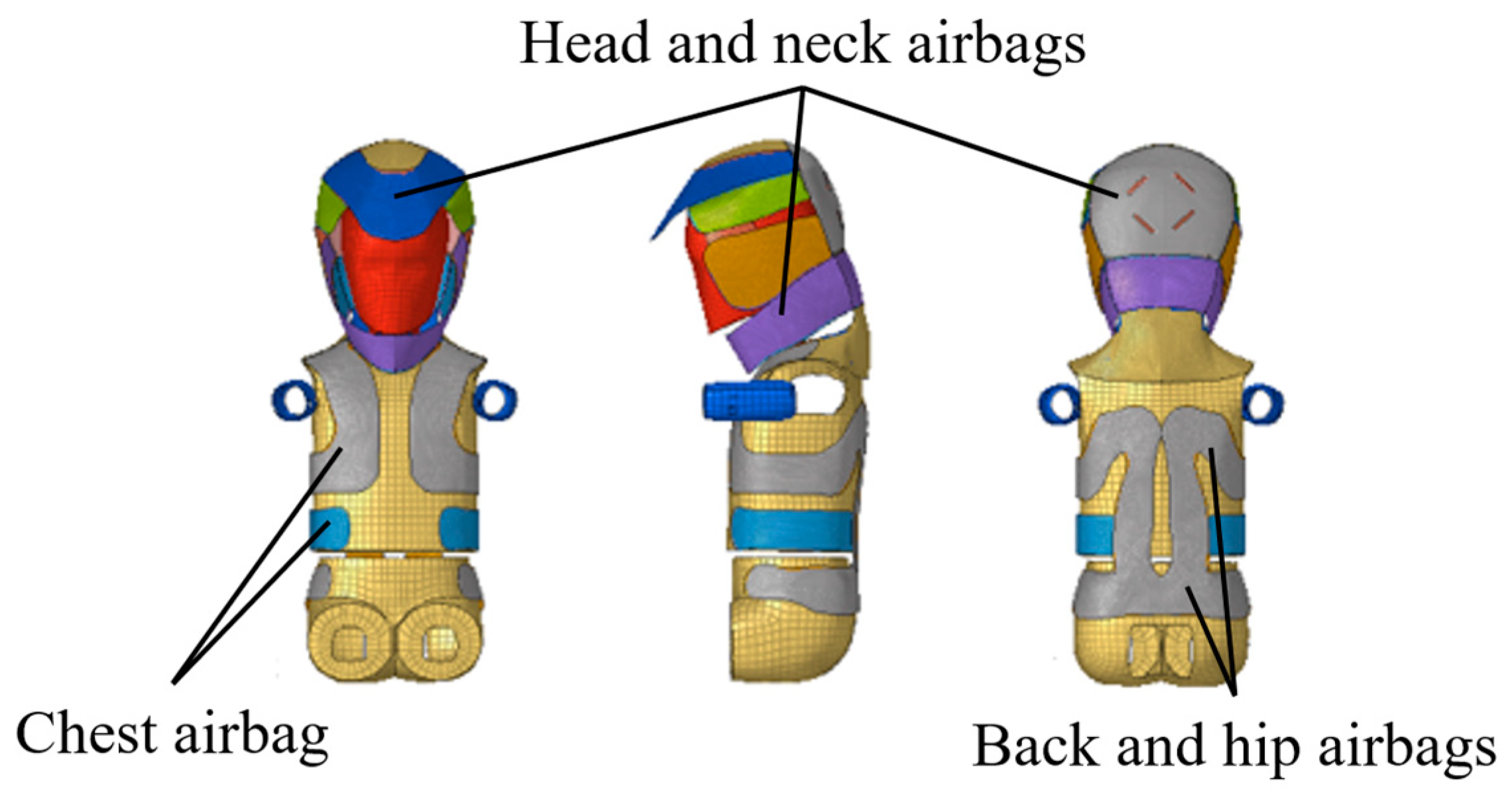
Figure 1. Wearable airbag design layout.
Applsci 13 03628 g001
Figure 2. Head airbag pulling strap position (left) and the detailed microstructures of the strap (right).
Applsci 13 03628 g002
Figure 3. ACH 27 hybrid inflator.
Applsci 13 03628 g003
Figure 4. (a) Temperature history curves obtained from a tank test; (b) the gas mass history curves.
Applsci 13 03628 g004
Figure 5. (a) FEA model of the tank test; (b) internal pressure history curve comparison between the modeling and the test.
Applsci 13 03628 g005
Figure 6. The front (left) and back (right) sides of the wearable airbag.
Applsci 13 03628 g006
Figure 7. The wearable airbag before (left) and after (right) inflation.
Applsci 13 03628 g007
Figure 8. Finite element model of vehicle–pedestrian collision.
Applsci 13 03628 g008
Figure 9. Pedestrian motion posture at different collision times: (a) pedestrian without airbag; (b) pedestrian with airbag.
Applsci 13 03628 g009
Figure 10. Lower limb acceleration of the HBM.
Applsci 13 03628 g010
Figure 11. Head acceleration histories and HIC15 of the HBM with and without the protection of the wearable airbag.
Applsci 13 03628 g011
Figure 12. Intracranial pressure map: (a) without airbag; (b) with airbag.
Applsci 13 03628 g012
Figure 13. Resultant acceleration curves of the chest.
Applsci 13 03628 g013
Figure 14. Shape of the head airbag under pulling strap control.
Applsci 13 03628 g014
Figure 15. (a) Airbag internal pressure under different gas masses; (b) Central thickness of the inflated head airbag under different pulling strap lengths.
Applsci 13 03628 g015
Figure 16. HIC15 head injury index distribution under different combinations of gas mass and pulling strap length.
Applsci 13 03628 g016
Figure 17. Comparison of airbag impact invasion: (a) gas mass is 20 g; (b) gas mass is 24 g.
Applsci 13 03628 g017
Figure 18. Pedestrian motion posture during collision.
Applsci 13 03628 g018
Figure 19. The area of adult head impact test in E-NCAP.
Applsci 13 03628 g019
Table 1. Comparison of injury indicators.
HeadChest
Injury IndicatorsHIC153 ms Resultant Acceleration of the Head (g)Intracranial Pressure (kPa)3 ms Resultant Acceleration of the Chest (g)
Without airbag1124.4111.2261.543.6
With airbag619.666.8168.634.8
Improvement rate45.9%40.0%35.5%20.2%
Disclaimer/Publisher’s Note: The statements, opinions and data contained in all publications are solely those of the individual author(s) and contributor(s) and not of MDPI and/or the editor(s). MDPI and/or the editor(s) disclaim responsibility for any injury to people or property resulting from any ideas, methods, instructions or products referred to in the content.