Abstract
Ceramic matrix materials have attracted great attention from researchers and industry due to their material properties. When used in engineering systems, and especially in aero-engine applications, they can result in reduced weight, higher temperature capability, and/or reduced cooling needs, each of which increases efficiency. This is where high-temperature ceramics have made considerable progress, and ceramic matrix composites (CMCs) are in the foreground. CMCs are classified into non-oxide and oxide-based ones. Both families have material types that have a high potential for use in high-temperature propulsion applications. The oxide materials discussed will focus on alumina and aluminosilicate/mullite base material families, whereas for non-oxides, carbon, silicon carbide, titanium carbide, and tungsten carbide CMC material families will be discussed and analyzed. Typical oxide-based ones are composed of an oxide fiber and oxide matrix (Ox-Ox). Some of the most common oxide subcategories are alumina, beryllia, ceria, and zirconia ceramics. On the other hand, the largest number of non-oxides are technical ceramics that are classified as inorganic, non-metallic materials. The most well-known non-oxide subcategories are carbides, borides, nitrides, and silicides. These matrix composites are used, for example, in combustion liners of gas turbine engines and exhaust nozzles. Until now, a thorough study on the available oxide and non-oxide-based CMCs for such applications has not been presented. This paper will focus on assessing a literature survey of the available oxide and non-oxide ceramic matrix composite materials in terms of mechanical and thermal properties, as well as the classification and fabrication methods of those CMCs. The available manufacturing and fabrication processes are reviewed and compared. Finally, the paper presents a research and development roadmap for increasing the maturity of these materials allowing for the wider adoption of aero-engine applications.
1. Introduction
Materials such as ceramic matrix composites (CMCs) have been the focus of research and being tested in different conditions for several decades now. They are known as a subgroup of composite materials and ceramics. Ceramic composites were developed to control and address problems that occurred with other commonly used ceramics, such as silicon carbide, alumina, silicon nitride, aluminum nitride, and zirconia. Such ceramics fractured with ease, revealing scratches and cracks while mechanical and thermo-mechanical loads were applied to them. To increase hardness and fracture toughness, several methods have been presented. As an example, mono-crystalline whiskers or platelets were added to the matrix, allowing for small improvement with the usage of only ceramic cutting tools [1,2].
In recent years, some improvements have been implemented with the consolidation of multi-strand fibers, which have proven to be crack, elongation, and thermal shock resistant, allowing for the creation of new applications in the aerospace and manufacturing industry [3]. This combination of materials has been adopted in the aerospace industry, making parts more resistant in extreme conditions enhancing the fracture toughness of the combined material system, adding higher strength and young’s modulus in the matrix, as well as being lighter compared with the alternative, more conventional structures [4,5]. According to the literature, continuous-length ceramic fiber with an elastic modulus is the most used type of CMC reinforcement or filler [6]. This allows the total composite stress to increase, enabling the expended energy during crack dissemination to bridge cracks without fracturing, providing the material with maximum tensile strength. This results in CMC materials being preferred over other conventional technical ceramics that exhibit similar low fracture toughness and low thermal shock resistance but more extreme brittle behavior [7,8].
In the aerospace sector, there have been challenges for the optimization of thermal insulation structures and the design and fabrication of non-eroding firing thrusters which can survive high thermal-structural and thermal chemical combustion environments without the use of a cooling system [9]. Parts, such as the inner surface of an exhaust nozzle, where the propellant flow is accelerated to supersonic conditions, are safety critical components, as the highest amount of shear stress, pressure, and heat fluxes are observed. These conditions result in ablation because of the heterogeneous reactions between hot gas and solid walls, leading to a decrease in the engine thrust [9,10]. On that basis, the most common materials used for this type of application are refractory metal carbides, ceramics, fiber-reinforced plastics, and graphite [10,11]. CMCs are potential alternative materials for such applications.
Furthermore, literature shows that certain categories of CMCs demonstrate superior performances under such high temperature and pressure operating conditions without, however, having an overall better performance [12,13,14]. In recent years this has been addressed through the adoption of ultra-high temperature ceramic matrix composite (UHTCMC) materials that exhibit preferable performance in high-temperature environments as well [15,16]. Such UHTCMC materials are composed of C or SiC continuous fibers in basic ceramic matrices [17].
The focus of the present research is on the classification of the available oxide and non-oxide CMC materials. A high-level classification is shown in Figure 1. Furthermore, a literature survey of the CMCs used for aero-engine applications is presented and compared to CMCs that have already been used in aero-engine applications regarding their mechanical and thermal applications. For the critical analysis comparison of the discussed materials, Ashby charts have been drawn to help with the material selection. The results of this survey were focused on creating an available classification of the existing oxide and non-oxide CMC materials. Moreover, a material property investigation took place, allowing for the comparison of both mechanical and thermal properties of oxide and non-oxide CMCs. This material property comparison will also help identify the selection of the correct material for the needed application.
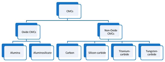
Figure 1.
Oxide and non-oxide CMC material categories.
Development of CMC roadmaps is also conducted to address the engineering issues that must be resolved to increase the maturity of CMC materials and enable their deployment in aero-engine applications. The roadmaps are developed based on historical information on CMC materials and their manufacturing processes that were acquired from a literature review of internet sources released up until the end of 2022. The progress of oxide and non-oxide CMCs in high-temperature industrial and aerospace applications are discussed. Furthermore, the developed roadmaps will also discuss the progress of the applied manufacturing processes of this type of composite. To conclude, the technological achievements of CMCs in high-temperature applications are critically discussed according to the collected literature.
2. Methodology
A broad systematic research of CMC materials literature was undertaken to reveal the use of the existing oxide and non-oxide CMCs in aero-engine applications. Keywords or phrases included “oxide CMC”, “non-oxide CMCs”, “material classification”, “alumina oxide”, “aluminosilicates”, “carbon, silicon carbide”, “titanium carbide”, “tungsten carbide ceramics”. Oxide and non-oxide CMC material searches were conducted, focusing on evidence-based research articles published between 1986 and 2022.
Titles and/or abstracts of articles identified through searching online literature databases, such as Scopus, Web of Science, and Google Scholar, were reviewed and evaluated for information relevance. Relevant articles were subjected to inclusion or exclusion criteria according to the research needs. Alumina oxide, aluminosilicate, carbon, silicon carbide, titanium carbide, and tungsten carbide material classification studies and application usage in high-temperature and pressure application studies were reviewed. Articles that did not focus exclusively on the classification of oxide and non-oxide CMC materials were excluded from further evaluation. Finally, data supporting the aerospace applications in which CMC materials have been used were sought and incorporated in the classification of the materials.
Figure 2 illustrates the growing interest in CMCs from the academic community. As can be seen, research on CMCs has been of constant interest since the 90s. However, it is obvious from Figure 3 that the research community has slightly moved its interest from non-oxide to oxide CMCs. In general, specific achievements, such as increasing the operating temperatures, introducing easier and more cost-effective manufacturing processes, and improving the thermal properties of the CMCs, resulted in more researchers being active on CMCs.
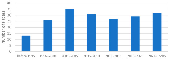
Figure 2.
CMC materials research published since 1986.
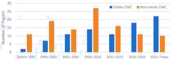
Figure 3.
Oxide vs. non-oxide CMC materials research.
3. Materials Classification
CMCs are classified as composite materials and technical ceramics. Their composition includes ceramic fibers embedded in a ceramic matrix producing a reinforced fiber-reinforced material. Ceramic materials are known for their brittle nature, but CMCs are tougher than their ceramic constituents. This is due to the efficient design of the fiber-matrix interface, which is responsible for spotting and deflecting cracks in the matrix, protecting the fiber reinforcement from catastrophic failure [18,19]. The literature analysis indicated that CMCs could be classified into two basic composite categories: oxide CMCs and non-oxide CMCs.
Oxide CMCs are oxidation-resistant materials and are used for applications with oxidizing environments, such as the hot section of turbine engine applications. Moreover, it has been found that the most used oxide composite base material families are alumina oxide and aluminosilicates [20,21]. These two base material families are then combined with several different ceramic and metallic fillers and reinforcements, which allow for the creation of the oxide CMCs. When both base material and filler reinforcement are oxide ceramic-based, an oxide-oxide CMC matrix is produced. A particular example is the combination of aluminosilicates with alumina/mullite fibers. Moreover, alumina can be successfully combined with boron carbide, silicon nitride, titanium carbide, and titanium dioxide filler reinforcements to create an oxide-CMC material. These material combinations will be discussed in greater detail in the following sections of this paper. Furthermore, oxide CMCs are considered to have better creep and corrosion resistance properties than non-oxide CMCs. Such properties have led to more research on this type of composite material in the past decade. Section 4 will focus on presenting the various types of oxide CMCs in more detail.
Non-oxide CMC materials have been in the research spotlight due to their good mechanical and thermal properties. They are composed of a non-oxide base ceramic matrix material and a filler/reinforcement (ceramic, metallic, plastic, polymer, etc.). Literature highlights carbon, silicon carbide, titanium carbide, and tungsten carbide being used as base matrix materials. For every material base matrix, there are several filler/reinforcements materials combined to create a non-oxide CMC material. Non-oxide CMCs, when subject to elevated temperatures, have low oxidation and corrosion resistance, whereas oxide CMCs are more oxidation and creep resistant in high temperatures, which will be discussed in the sections below. Section 5 will focus on presenting the various types of non-oxide CMCs in more detail.
4. Oxide CMCs
The main reason for using Oxide CMCs (O-CMCs) compared with using other technical ceramics is due to the low fracture point under high mechanical or thermal load occurring to cracks made by small defects or scratches [21]. This is because O-CMCs include inorganic oxide compounds of metallic or metalloid elements with oxygen, such as alumina, beryllia, ceria, and zirconia. According to the reported research, though, not great breakthroughs have been achieved in terms of improving crack propagation, with only the multi-strand fibers enabling a small increase in the crack, thermal shock, and elongation resistance, allowing for the usage of these materials in new applications [20]. Furthermore, the applications in which O-CMCs are used are limited to a maximum temperature of 1200 °C [21]. This is due to degradation in the mechanical performance of the oxide reinforcing fibers occurs, resulting in minimizing the tensile strength values of the composite [22]. To avoid this, the literature suggests the use of a weak fiber-matrix interface so that when the material is under load, the crack will occur in the weak fiber-matrix interface. This allows composites to be able to withstand a larger amount of mechanical load [23].
The commercialization of high-strength oxide fibers started in the 1990s when the first alumina-mullite CMCs were manufactured [2]. Alumina-mullite composites with almost pure alumina fibers have the highest strength among the oxide fibers and also high creep and oxidation resistance [5]. Nowadays, new material matrices have been implemented for the construction of oxide CMC matrices, as shown in Figure 4.
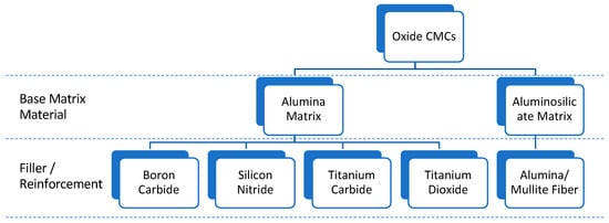
Figure 4.
Oxide CMC material categories.
Figure 4 shows the available oxide ceramic matrix composite materials and the different types of matrices and material compositions. This type of CMCs can be used for both structural and ultra-high temperature applications. More specifically, there are two basic types of oxide base material matrices, alumina, and aluminosilicate matrix, which can be used either as the base material or the filler/reinforcement. The alumina matrix can respectively be combined with boron and titanium carbides, silicon nitrides, and titanium dioxides. On the other hand, the alumino-silicate matrix can be successfully combined with alumina/mullite fibers to create an oxide CMC material composition. These categories will be discussed in more detail in the following paragraphs.
4.1. Alumina Matrix CMCs
Alumina is a mixture of aluminum and oxygen with high thermal conductivity and is widely used as an electrical insulator. It has high hardness, high compressive strength, and good chemical and thermal stability [7,24]. However, its application as a structural material has been limited by its low fracture toughness and strength. This is attributed to the fact that cracks easily propagate, and therefore, they might fail unpredictably during service [25,26,27,28].
Literature indicates a small amount of developed ceramic oxide interphases composed with the alumina matrix, while the largest number of studies are experimental, conducted with the use of metal oxides (lanthanum vanadate, calcium tungstate, etc.), which have been proven to present processing challenges [29,30]. Alumina matrices are used predominantly for O-CMC applications due to their high mechanical and thermal properties and low density. Their chemical stability is a factor that allows them to be combined with other available oxide fibers enabling better overall temperature capability of the composite material. Some of the most used alumina-based CMCs include boron carbide, silicon nitride, titanium carbide, and titanium dioxide as secondary composite materials (Figure 4). In the following paragraphs, these composite systems will be discussed in more detail.
- Alumina and Boron Carbide
Boron carbide has high strength and hardness, and it is the third hardest material after diamond and boron nitride. Furthermore, it also exhibits low density, neutron absorption capability, and acceptable chemical stability values. These properties allow the boron carbide to ionize radiation [31]. The combination of alumina matrix with boron carbide creates a high-temperature and high-pressure-resistant composite CMC material which can be used in high structural applications [31,32]. The literature indicates that 10–40% vol of B4C whiskers have been tested and showcased the higher density results. B4C between 5 and 15 vol% showed that it could assist in the sintering of the alumina densification by methods other than grain development inhibition. The composites with 10–20 vol% B4C whiskers have enhanced fracture toughness of up to 6.2 MPa.m1/2 [33].
Due to their high hardness and fracture toughness, composites made of aluminum oxide (Al2O3) and boron carbide (B4C) have been suggested for use in high-temperature applications and as cutting tools. The composite Al2O3 and B4C coatings were made using the air plasma spraying technique. On ordinary carbon steel substrates, plasma was used to spray three different Al2O3:B4C composition ratios at 90:10, 80:20, and 70:30 by weight. Using scanning electron microscopy (SEM), microhardness tests, X-ray diffraction (XRD), and the flash diffusivity method, the impact of B4C content on the microstructure, hardness, porosity, and thermal diffusivity of the coatings was investigated. The plasma spray’s characteristics were refined to attain a theoretical density of about 90% [34].
Sintering is one of the most used manufacturing techniques for boron carbide [35]. On the other hand, sintering boron carbide in high densities is challenging to accomplish, but literature shows that if sintering methods are executed correctly, they offer high overall thermal properties [36]. In recent years, hot pressing of sintering additives has also been successful, although it required high temperatures to keep a fully dense boron carbide body [37]. Experimental studies have been presented combining various metallic phases in the boron carbide matrix, but the results could not be attained at the required temperatures without fracturing [38]. On the other hand, when boron carbide was tested with oxide matrix materials as sintering aids (non-reactive sintering), better results were achieved due to their high chemical stability [39]. Alumina oxide proved to increase the sinterability of boron carbide at a higher rate. In addition to that, an increase in density, hardness, flexural strength, and fracture toughness was also accomplished, making it a suitable base material for the creation of a highly usable CMC [39].
- Alumina and Silicon Nitride
Silicon Nitride (Si3N4) is used in CMCs in particulate form with high mechanical strength and wear resistance. It has high dielectric properties, and as such, it is a good energy insulator. Moreover, silicon nitride has been developed and used in structural applications, such as valves, gas turbine components, and turbocharger rotors [16,17]. Despite its high-temperature resistance and strength, when exposed to high mechanical and thermal conditions, it fractures. This is the biggest challenge in engineering applications of this type of ceramics. Introducing silicon nitride in alumina matrix (Al2O3/Si3N4) increases overall mechanical properties by a great margin [40,41]. Additionally, this class of CMCs can be manufactured with relatively low-cost processes [6].
Literature indicates combinations of Si3N4 and Al2O3 are used in consolidation. The discovery of an enlarged ß -Si3N4 structure known as the ß -phase was first reported independently by various researchers [42,43]. Recently, it was discovered that this ß phase is a solid solution of AIN-Al2O3 in ß -SiN4 instead of what was previously believed to be a solid solution of Al2O3 to ß -Si3N4. When Si3N4 and Al2O3 are hot pressed or pleasureless sintered, dense solids are created that are principally composed of b and one or more minor phases. SiAION is the name given to this kind of material today. Candidates for high-temperature structural applications include SiAlON, Si3N4, and SIC [44].
Further investigations demonstrate the thorough mixing and contact of the Si3N4 and Al2O3 powders that was ensured by intense stirred-ball-mill blending of the starting powders [44]. Powder mixtures of different Al2O3/Si3N4 mole ratios were pressure sintered in a vacuum at temperatures ranging from 1100 to 1700 °C (2010 to 3090 °F) for studying the kinetics of reaction and densification. During heating and at equilibrium temperature, press ram movement resulting from the application of constant pressure (a measure of powder compaction) was recorded. In order to explain the production and densification of SiAlON as a function of temperature and the Si3N4:Al2O3 mole ratio, powder compaction rates, and end-point densities were coupled with X-ray diffraction and metallographic investigations [45,46].
Further development of the material systems (thermal stability, non-oxidizing interface, and matrix), low-cost manufacturing processes, and non-destructive evaluation techniques are investigated [47,48]. Literature reports experimental studies where Al2O3/Si3N4 is proposed for hybrid bearing applications, where the inner and outer races are created from steel, and the balls are manufactured from such CMC. Components with increased compressive strength (12.5% increase) are reported [49].
The functional graded material of Si3N4-Al2O3 is developed by using a polypoid functional gradient and is successfully manufactured with the powder stacking method, resulting in a crack-free joining of the two materials. For the powder stacking method to be successful, the process includes the stacking of 20 layers of polyploids with a thickness of 500 μm each to reduce the thermal residual stress resulting in a smooth gradient [50].
- Alumina and Titanium Carbide
Titanium carbide (TiC) is a very hard refractory ceramic material. It has been tested to have the highest specific strength and modulus, high melting point, and electrical and thermal conductivity. Due to its high mechanical and physical properties, TiC has been used as reinforcement in titanium matrix composites [51]. Several researchers have described the ability of TiC particles to heal surface cracks in the alumina matrix [52].
Alumina and titanium carbide is a new combination, and thus a very small amount of experimental research has been reported. Experiments have been created using TiC in CMCs in the range of 15–30%. More specifically, Al2O3–TiC composites with various amounts of TiC, from 16 to 30 vol.%, were pressureless-sintered using 1 wt% Al as an additive. As the volume fraction of TiC grew, the hardness and toughness gradually increased as well. As the TiC volume percentage rose from 0.20 to 0.23, the electrical conductivity increased along with it and grew by about 10 orders of magnitude. The best wear resistance was found in a sample with a TiC volume fraction of 0.23, which is close to its saturation point [53].
Some newly developed fabrication techniques include the cementation process, where the provided alumina oxide, titanium particles, and activated carbon fine precursor are brought together to react upon sintering, creating a functionally graded-cemented layer. This technique offers lower synthesis costs without losing any of the mechanical and thermal strength of the final composite [54].
Such CMCs are mostly used as a slurry mixture and for manufacturing wear-resistant tools, protective coating, and cutting tools, due to their good chemical inertness and thermal conductivity as it is considered prominent reinforcement material [55]. Further experimental research on such CMCs focused on aero-engine applications demonstrated that the material cracks were healed when the composite was exposed to a high-velocity gas mixture at a temperature of 1000 °C and a low oxygen partial pressure [56].
Using sintering methods, researchers proved that the in-situ synthesis of TiC creates composites with high density, exhibiting enhanced toughness in comparison with Al2O3 oxide ceramics [57]. Further investigations have been conducted on the manufacturability of such CMCs, focusing on mechanical milling, cementation process, and pressure-less sintering, but the results varied without having a consistently successful outcome [58].
Another important use of the in-situ synthesis of TiC particles is for healing surface cracks in the alumina matrix. Literature suggests the use of 15–30% volume percentage of TiC in temperatures ranging from 400 to 800 °C at a certain time. The results showed that the composite obtained maximum strength when it contained a 30% volume percentage of TiC [56]. Furthermore, surface cracks were healed when the composite was exposed to a combustion chamber with a high-velocity exhaust gas mixture at a temperature of 1000 °C and a low oxygen partial pressure [52].
- Alumina and Titanium Dioxide
Titanium dioxide (TiO2) particulates are mainly produced in the form of white powder pigment due to their brightness and very high refractive index. This means that a low level of pigment is required to achieve a white opaque coating. One of the major advantages of TiO2 is its resistance to discoloration under ultraviolet light. It is mainly used in coatings, plastics, fibers, and pharmaceuticals. In mildly reducing atmospheres, TiO2 loses oxygen and turns into a semiconductor [59].
The combination of alumina and TiO2 particulate reinforcement allows for highly reactive powder with low thermal expansion, thermal conductivity, and high thermal shock resistance [60]. The mechanical properties of such CMCs are similar to those of alumina and titanium carbide ones and comparatively higher than all the other oxide CMCs [61].
Typical applications for such CMCs are crucibles, nozzles, tubes, thermocouples, and coatings (for thermal corrosion and wear protection) [62]. Researchers have studied the characterization of Al2O3 coatings with the addition of TiO2, as well as the effects of TiO2 in addition to alumina base plasma sprayed coatings concluding that titanium dioxide lowered the microhardness of the alumina coating [18]. This resulted in a decrease in the hardness of the titanium oxide coatings while the toughness values of alumina coatings increased. Literature also indicates that the combination of Al2O3 and TiO2 into a ceramic resulted in higher microhardness values of the sample compared with adding both materials separately [63,64].
4.2. Aluminosilicate Matrix CMCs
Literature review indicates that aluminosilicate (Al2O3/SiO2) ceramics improve the bonding strength of oxide CMCs and are mainly composed of alumina, silica, and mullite [55]. SiO2 matrix is a potential material for high-temperature ceramic applications due to the advantage of low and stable dielectric constant, high chemical and good mechanical stability, and excellent thermal shock resistance. The literature also shows that aluminosilicate CMCs are applied in antenna housing and aerospace engineering applications [65].
Mullite ceramics are known to have high creep and thermal shock resistance but less strength resistance at high temperatures [66]. Furthermore, mullite ceramics have lower mechanical properties in comparison with other ceramics at room temperature applications [67,68]. For their creep and oxidation resistance properties to be exploited, researchers introduced second-phase enhancers in the form of particles, fibers, and whiskers, allowing for better overall property results [69]. Some of the most popular composite material filler reinforcements are zirconia and alumina, and they are composed of a mullite base matrix with electrophoretic deposition or sintering [70]. This way, the mechanical properties of the mullite-based matrix increased more than double the use of pure mullite.
- Aluminosilicate matrix and alumina/mullite fiber CMCs
Research studies show that the Aluminosilicate and Mullite composites have been used for complex-shaped components, such as the heat insulation tile of the combustion chamber, which was verified by simulation tests [71,72]. Literature studies showcased the thermal shock resistance of Al2O3/SiO2 being able to withstand very hard conditions, similar to those nickel and metal alloys withstand in aero engine applications, by using the residual stress field theory of periclase-hercynite refractories [65,73].
Aluminosilicate CMCs’ residual strength is higher than the majority of other oxide CMC materials [74,75]. It was also found that Al2O3/SiO2 composites exhibit high strength, excellent oxidation resistance, and environmental stability at high temperatures [68]. In aluminosilicate CMCs, the most common composition of alumina base matrix ranges between 50 and 90% Volume of fraction (Vf), while the filler reinforcement materials compositional summary depends on the synthesis procedure used to create the aluminosilicate composite [76].
Studies also investigated the porous Oxide CMCs in greater depth, which allowed the synthesis of Nextel 720 fiber-reinforced porous mullite-Al2O3 composites with the use of the infiltration-wound (SI-W) process. This resulted in aluminosilicate composites having high tensile strength (up to 149 MPa). These results allowed this type of oxide CMCs to be applied in the inner and outer linings of the aero-engine combustion chamber and the hot parts of a spacecraft nose cone [19].
Literature suggests the use of aluminosilicate matrix CMCs in aerospace applications [77,78]. Until now, aluminosilicate CMCs have been used as environmental barrier coatings (EBCs) and thermal barrier coatings (TBCs) in the hot section of gas turbine engines [78]. Research has proved that aluminosilicate CMCs can replace nickel superalloys as they provide better temperature and corrosion resistance in oxidating environments [79]. NASA has also been implementing these types of CMCs in ultra-efficient engine technology by implementing aluminosilicate CMCs as a three-layer barrier coating system to avoid crack formation [80].
A very common manufacturing method for porous Oxide/Oxide CMCs, that also allows the preparation of Nextel 720 fiber-reinforced porous mullite-Al2O3 composites is the slurry infiltration-wound (SI-W) process [81]. Further research examples have shown that the sol-gel infiltration process is also used to manufacture aluminosilicate composites and, more specifically, Nextel/A and Nextel/AS commercially available ceramic matrix composites. Some characteristics examples describe the process achievement by drying the laminates with a vacuum bag technique in low pressure and temperature and finishing with pressure-less sintering, which allowed for no coating to be used [71,82].
5. Non-Oxide CMCs
Non-oxide CMCs are technical ceramics displaying covalent bonds, which mainly include conductive carbides and non-conductive nitrides [83]. The composition of non-oxide CMCs allows for high toughness, although their constituents are very brittle. This is achieved through the design of the fiber/matrix interface, which is capable of deflecting cracks formed when a large amount of load occurs in the brittle matrix, avoiding an early failure of the fibrous reinforcement, such as the O-CMCs. In more detail, a thin layer of a compliant material with low shear strength is added to the fiber surface, creating an interphase that reacts as a mechanical fuse [84,85].
Non-oxide CMC combinations provide different material properties and require different manufacturing procedures, which determine their usage for a variety of applications in different industrial sectors. The literature highlights that non-oxide CMC is the most commonly used CMC for high-temperature applications [86]. They can be separated into composite material categories, which include carbon, silicon, titanium, and tungsten carbide particles. Their mechanical and thermal properties allow them to be used as cutting tools, super-hard abrasives, rocket nozzles, electrodes for metal melts, as well as heating elements.
The most used structural non-oxide materials are silicon carbides, known as sialons, which are nitride-based ceramics with a wide range of oxide content. They are mainly processed in high-temperature environments with inert gases to reduce oxidation [87,88,89]. Non-oxide CMCs composition includes different matrices which can be used as base material and different fillers and reinforcements, as shown in Figure 5. The four main material matrices include carbon, silicon carbide, titanium carbide, and tungsten carbide.
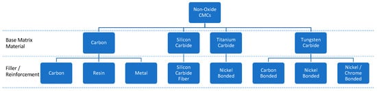
Figure 5.
Non-oxide CMC material categories.
5.1. Carbon Matrix CMCs
Carbon as a solid varies in mechanical and thermal properties. Some carbons are highly porous, and others are impervious to liquids and gasses [9,90]. These conditions result from structural effects of the geometry and amount of carbon phases with a crucial effect on the crystalline order.
The literature review highlighted that there are three common carbon-based material categories: Carbon/Carbon, Carbon/Metal, and Carbon/Resin composites. Carbon-based composites are widely accepted in the aerospace industry. However, pure carbons and composites have oxidation problems and require additional oxidation-resistant reinforcements or coatings [91,92,93]. Carbon fused ceramics as a base material can be used to improve the composite’s oxidation resistance and lifetime. These carbon-based ceramics include silicon carbide (SiC) due to its high oxidation, temperature, thermal shock stability, and high creep resistance [94,95].
Moreover, the carbon base matrix is combined with carbon fibers (C/C) used as fillers/reinforcements. The carbon fibers must be aligned parallel to the external load of the carbon matrix and should be as long as possible. This allows the application of the maximum stress in the C/C CMC matrix [96,97].
C/C composites have been applied in ballistic missile nose tips, nose caps, and leading edges of space shuttles [98]. Although there has been noticeable development in this type of ablative composite technology, there are still a number of applications where it cannot be used. These include the production of gas turbines, turbojet engines, internal combustion engines, nuclear reactors, etc. As all these systems operate under severely harsh service environments, significant advances in ablative systems could provide a huge success in the development of such structures [99].
- Carbon/Carbon matrix CMCs
Historically, the main reason why composites based on ceramics and carbon fibers were fabricated was to avoid the failure of the ceramic parts at increased loads. The production of carbon matrix CMCs requires physical and chemical compatibility between the carbon and ceramic particles. Carbon/carbon CMCs are used both as a filler and a base matrix, where the latter is the connecting source for the fillers, allowing for the composite to have different structures and textures [100]. Some examples where carbon is used as a filler or reinforcement are carbon fibers, which allow for a variety of different property composites by selecting the needed precursors and shapes (strand, yarn, or chopped). In addition, for the fabrication of carbon-ceramic CMCs, the composite must have a service temperature that reaches up to 1600–1800 °C, as this is the temperature where most ceramics crystallize.
Carbon/Carbon composites, also known as carbon fiber reinforced carbon (CFRC) or reinforced carbon/carbon (RCC), are CMC material matrices including carbon fiber reinforcements in a matrix of graphite [101,102]. Over the past three decades, carbon fibers have been one of the most recognizable reinforcements for advanced composites used in aerospace applications [103]. They are a few microns thick, lightweight, very strong, and stiff black synthetic fibers, consisting of long aromatic molecular chains comprising mainly carbon. Their main advantage is the increased toughness. Research has shown that carbon fibers can improve mechanical and thermal properties by up to ten times without increasing the final weight of the composite. Carbon composites have been tested under high temperature and pressure conditions, which allows them to be used in different types of ceramic, polymer, and metal matrices [104].
Nevertheless, carbon fiber-reinforced carbon CMCs exhibit high fracture toughness and pseudo-plasticity [10,76]. They are heat-resistant but suffer from drastic material consumption in oxidizing atmospheres due to the oxidation of carbon and the creation of carbon oxide (CO) and carbon dioxide (CO2) [47].
Such CMCs have high stiffness and strength. Such properties are, to some extent, achieved because of the control of microcracks in the interphase of the carbon matrix and fiber matrix and the fact that these are practically closed when exposed to high temperatures. They can be used in environments where temperature can approach 3000 °C [105]. In addition to their good strength and stiffness, they have low thermal expansion and good thermal shock resistance, as well as good creep and corrosion attributes. Their mechanical strength is increased with temperature [106]. Research indicates that the strength of advanced Carbon/Carbon CMCs can increase with temperatures close to 2000 °C. Furthermore, their properties vary depending on the fiber fraction, the type and structure of the carbon fiber, and the processing cycle used to fabricate the composite [107]. Therefore, they have higher stiffness, strength, and thermal conductivity across the fiber axis, while their mechanical and thermal properties are lower along the fiber direction.
Most C/C composites are manufactured using the preformed yarn method (PY), which consists of a bundle of carbon fibers in a matrix of coke and pitch binder powders [108]. This method allows faster production than other conventional methods (impregnation of the chemical vapor deposition method). The standard composition manufactured by this type of method is between 40–50% volume fracture of carbon fiber content by volume, which after graphitization at 2000 °C becomes 100% of carbon [109]. Other researchers have created Carbon/Carbon CMCs using different base carbon fibers weaved together and densified by chemical vapor infiltration (CVI), which is recognized as one of the most used manufacturing processes to fabricate this type of composite [110].
The mechanical properties of Carbon/Carbon composites show that this type of composites have lower densities than other ceramic components with also thermal properties higher than copper and silver, making them suitable for usage in aero vehicles [93,106,111,112]. An example of aeronautical applications of Carbon/Carbon CMC is the wings and the fuselage nose, created for the American Space shuttle, which was able to withstand 100 missions under extreme re-entry conditions [113]. The aerospace industry requires reliability and reduced system costs; hence carbon fibers are replacing previously used multiple components with a one-piece assembly, having in most cases one-tenth of the density of previous steel components but offering similar strength and heat resistance [113]. Other commercial applications that use Carbon/Carbon composites include furnace fixtures, heatshields, heating elements, and load plates [114].
- Carbon/Resin matrix CMCs
Resin is a structural material that has been introduced for aerospace applications due to high-temperature resistance in engine environments. This type of fiber reinforcement is used in a ceramic composite matrix to bridge cracks and toughen the matrix by crack blunting and debonding at the matrix interface [115,116,117]. When the resin filler/reinforcement is combined with carbon, the composite which occurs benefits from a high strength to low weight ratio increase. In addition, research has shown that the heat resistance, strength, and stiffness of the resin filler/reinforcement has been improved when carbon is added [118,119]. The resin, on the other hand, allows the composite to conduct force to the fibers and secure them when exposed to high-pressure [118,119].
The mechanical properties of carbon/resin composites have been improved drastically. More specifically, the maximum shear strength has been increased between 10–75% depending on the type of manufacturing process and the added interface of the composite. Surface roughness has also increased [120,121,122]. Such CMCs present improved flexural modulus. The thermal conductivity of the carbon/resin composite is improved at room temperature and can withstand higher temperatures without failing [123].
The fabrication of CMCs quite frequently results in the generation of microcracks [118,124]. Carbon-fiber-reinforced ceramic matrix composites, however, exhibit fewer microcracks and allow for higher mechanical strength combined with lower density [125]. The manufacturing processes used to create carbon/resin composites are expensive and time-consuming. However, they are frequently preferred as they can be used in applications where a high strength-to-weight ratio and stiffness are required [126]. Many attempts to reduce the processing times and cost have allowed for the development of a large variety of fabrication methods, which create complex geometries without harming the fiber and protecting the composite from oxidation due to the reaction of carbon fiber with oxygen at any temperature as low as 500 °C [126]. Some of the most used manufacturing procedures are precursor polymer infiltration and pyrolysis (PIP), which turns out to be similar to the formation process of C/C CMCs, due to allowing for low processing temperature, easy-to-control ceramic compositions, near net shape technologies, and a range of complex reinforcements [127].
Carbon/resin composites are mostly known for their use in automotive applications, used as fuel cells, offering high power and strength, and high modulus, which allows for battery bipolar board to have better wear resistance and longer lifetime and reduces the weight of the vehicle [128]. Another characteristic example of carbon/resin composite usage is in aerospace primary structures, such as autoclaves, and further research claims that they can be used for manufacturing rotor blades [129].
- Carbon/Metal matrix CMCs
According to the literature review, composites made of carbon-fiber/metal-matrix will be the basis for the breakthrough in aerospace materials. They are high-temperature composites based on refractory metals and high entropy alloys, as well as on intermetallics [130]. Carbon ceramic materials have mostly been recorded to be used as fibers and fillers in metal base matrices creating metal matrix composite materials. More recently metal impregnated carbon ceramic matrix composite materials have also been researched. The base matrix of the composite includes carbon as the base material and a metal-impregnated carbon fiber as a filler reinforcement. Various manufacturing approaches for fabricating CMC composite and metal matrix composite materials have been tested.
The metal particulates may be selected from a range of magnetism-susceptible metals. These metals include nickel, nickel alloys, iron, and alloys of iron/steels, cobalt, and cobalt alloys. The particles may also be more thermally conductive composite materials, comprised of particles that have a metallic layer over an inorganic particle, allowing them to be less mechanical and thermal properties limitations [131]. In addition, the metal particulates are finished at a fine level, which allows them to facilitate infiltration into inter-fiber spaces in plies. An embodiment example would include plies from carbon fiber, and the metal particulates may be nickel, sized in the range from about 1 nm to about 100 microns.
5.2. Silicon Carbide Matrix CMCs
Silicon carbide fibers have high tensile strength, high elastic modulus, and very good thermal stability, making them one of the best candidates for reinforcement [129,132]. Silicon carbide ceramic matrix composites include a silicon carbide matrix phase and a fiber phase, fabricated with various manufacturing processes. The SiC fiber preform is infiltrated and densified with a SiC matrix, enhancing the final composite with improved mechanical and thermal properties. Monolithic SiC ceramics have very low fracture toughness and cannot withstand very high temperatures, issues that are addressed by SiC/SiC CMCs [129,133].
Silicon carbide CMCs are one of the most popular composites used for high-performance applications. This is due to having lower density, higher toughness, higher damage tolerance, and better creep and wear resistance than other carbon fibers and oxide/oxide CMCs or monolithic ceramics [129,134]. SiC/SiC CMCs have higher temperature capability, lower thermal expansion, and better thermal conductivity than most metallic superalloys and CMCs, as well as monolithic ceramics [129,132,135].
It has been found that SiC fibers manufactured with polymer pyrolysis serve a finer and more flexible diameter form rather than those produced with CVD or sintering processes [136]. On the other hand, SiC/SiC CMCs are used in aircraft applications such as turbine engine hot section components [137]. In recent years melt infiltration (MI) of SiC/SiC CMCs succeeded at a temperature limit of 1316 °C due to the existence of silicon in the matrix [138]. MI process increases maximum porosity levels, allowing for lower thermal conductivity and lowering the thermal shock resistance [138]. The correct fabrication of the fiber/matrix interphase allows deflecting matrix cracks and prevents early failure of the fibrous reinforcement [139,140,141].
Research also indicates that SiC/SiC CMC systems, made from up to 45% of the volume fraction of woven and quasi-isotropic laminate silicon carbide fibers, can withstand temperatures up to 1300 °C, which are well above the temperature resistance capability of any metallic alloy [142]. By using this type of CMC material, the MI step for filling pores in the SiC matrix can be eliminated [143]. After testing the mechanical and thermal properties of the SiC/SiC, it was also shown that this type of CMC fabricated with the CVI processes offered greater tensile strength and strain, as well as better thermal shock resistance [144]. Furthermore, studies proved that the creep and fatigue behavior could be increased through the chemical vapor infiltration-processed SiC matrices that were reinforced with low modulus SiC fibers such as Hi-Nicalon in a range of 1000–1300 °C [145].
Results showed that woven laminates were able to withstand high temperatures without microcracking, but in lower temperatures, results showed that creep and fatigue occurred in the composites after a few hours [146]. This allows them to be used as components in gas turbine applications, thruster nozzles, and heat exchanger applications.
5.3. Titanium Carbide CMCs
Titanium carbide (TiC) is a very common reinforcement in a variety of different matrix composites. TiC presents very good physical properties, such as a high melting point, low density, high hardness, and mechanical stiffness, as well as high thermal and electrical conductivity [147]. TiC is made from titanium dioxide reacting with carbon at temperatures greater than 1800 °C. It is a very hard refractory material with similar properties to tungsten carbide, but to develop a more efficient and hard-use matrix, TiC is bonded with nickel matrix cermet (ceramic metals) so that better precision, cutting speed, and smoothness of the final material is achieved [148]. This occurs because the chemical reaction between TiC-Nickel and Molybdenum (TiC-Ni-Mo) creates well-bonded phases within the cermet, and carbides dissolve [149]. This combination allows for higher hardness with lower density and a better modulus of elasticity. On the other hand, the thermal conductivity of titanium carbide and CMCs are found to be high, such as the thermal expansion, which makes the composite a good conductor of heat [149].
Through time, many different compositions of nickel-bonded titanium carbides have been tested in a wide span of temperatures and compositions [150]. It was found that compositions with a lower percentage of nickel would allow for increased interphase bond strength and a decreasing number of microstructural flaws (which are stress concentrators) needed for nucleation and propagation of cracks, resulting in the removal of materials [151].
Research studies mention that liquid phase sintering is a technique used to create titanium carbide CMCs [151]. Various compositions of TiC/NiMo cermet samples were manufactured and tested by changing the material weight compositions, resulting in higher nickel bond content, decreased bulk hardness of the TiC/NiMo composites, and higher wear rate [152]. Besides liquid phase sintering, melting solidification, and powder metallurgy (conventional pressing and sintering) techniques are implemented to fabricate this type of CMCs, due to the high Vickers Hardness of the TiC matrix [151,153,154,155]. However, because of TiC’s low density, a uniform distribution of hard phases is not easily achieved. During solidification, the TiC particles show a gradient distribution in the matrix with respect to size and volume fraction [156].
5.4. Tungsten Carbide CMCs
Tungsten carbide (WC) is a chemical compound consisting of equal portions of tungsten and carbon atoms [157,158]. The most basic form of this material is fine-grey powder [157]. Its mechanical and thermal properties are equal to titanium carbide (TiC), making it ideal for extremely high temperature and stress applications, although it is very hard to work with it, so it is mostly used for making cutting tools [159,160]. WC is combined with four different material families creating different CMC material combinations. These material families are carbon, cobalt, nickel, and nickel/chrome bonded matrices.
- Tungsten Carbide-Carbon CMCs.
Tungsten carbide includes ingredients of cemented carbides which are based on WC-Co, which, apart from great hardness, offer high wear resistance and hardness retention when exposed to high temperatures [159]. On the other hand, research has shown that tungsten carbide and generally cemented carbides have low corrosion resistance when exposed to corrosive environments due to the cobalt binder [161]. Hence many tests have taken place by reducing the amount of binder material and replacing it with another filler or removing the binder material completely [161,162]. The binders used to reinforce tungsten apart from cobalt are mainly carbon (C) and nickel (Ni).
The most researched cementing material for WC is the WC-Co system. This is because Co allows for very good wettability and adhesion with tungsten carbide, as well as increased strength and toughness [163]. Furthermore, researchers proved that the abrasion resistance and hardness are oppositely proportional to the added percentage of cobalt due to the composition, chemical purity, and micro-structure of the carbides existing in the matrix [164,165]. Studies also demonstrated that the higher the volume fraction of Co reinforcement, the higher the fracture toughness but the lower the hardness and abrasion resistance [165].
The fabrication of this type of composite started in 1957 when other researchers tried to fabricate pure WC by using conventional sintering techniques, but it was found that the densification of the nanocrystalline fiber of WC-Co powder could be treated only in solid-state, meaning that it could not be processed [166,167]. Researchers managed to completely densify pure WC with vacuum or pressurized gas sintering, creating ultra-fine WC starting powder that, with further processing, could achieve a high hardness and wear resistance, avoiding any large amounts of grain growth inhibitor [167]. Furthermore, the literature shows that the reduction of WC grain size in WC-Co hard metals allows for the solubility of WC when Co is in the liquid or solid phase, allowing for improved strength and wear resistance [167]. Further research shows that the abrasion resistance of the nanostructure of this type on CMC is about twice the size of other types of ceramic composite filler/reinforcement, such as ZrO2 and SiC [168].
The addition of free carbon into the tungsten carbide matrix can upgrade the densification process of WC and reduce or even extinct the creation of a brittle phase composition when exposed to temperatures over 1800 °C [162]. Studies have also proved that the addition of carbon in WC sinters formed graphite nanolayers on inter-granular boundaries, improving the thermal conductivity of the polycrystals close to double [169]. Although, research showed that large amounts of added carbon in a WC matrix cause abnormal grain growth of tungsten carbide, allowing for the creation of cavities and pores in the sintered products [170].
- Nickel and Nickel/Chrome bonded Tungsten carbide CMCs
Nickel is a material cheaper than Co, easily available with good toughening properties, and with lower ductility than WC-Co [171]. In addition, it is used as a binder for tungsten carbide composites to improve corrosion and oxidation resistance. It has high-temperature strength, high temperature, and high wear resistance [172].
An increasing number of research papers focused on Ni-base cemented carbides have been published in recent years [173,174]. Both cobalt and nickel exhibit good wettability with WC, and fully dense hard metals without high porosity can be produced [175]. The major difference between them is the higher stacking fault energy of Ni which allows for lower hardening rates [176]. That is why the hardness and strength of WC–Co grades tend to be greater than those exhibited by WC–Ni ones. Although, an increase in the work-hardening rates of the Ni binder may be achieved by adding other elements, such as chromium or silicon [177]. Furthermore, Cr additions result in a large increase in the corrosion resistance of WC–Ni hard metals [178].
Research approaches have proven that nickel-based tungsten carbide, with a composition of WC up to 60 wt%, can be produced with laser cladding and reveal zero cracks. From this research, it was also obtained that on top of laser cladding parameters, a small percentage of dissolution of the tungsten carbide particles occurs, allowing for finely dispersed mixed carbides, as well as the creation of a metal phase around the primary carbides [179]. Moreover, WC-NiCr premixed powder was tested on low-carbon steel by laser cladding. The results showed that the selection pore-free layers had minimal dilution and good metallurgical bonding without cracks, while the composition of Cr was about 8 wt%. In addition, the variety of tungsten carbide-nickel bonded matrices has a low composition of Cr and Ni, with the greatest number of percentages to be close to 10 wt%, to achieve higher toughness and better wear resistance [180].
6. Mechanical and Thermal Properties of CMCs
CMCs have a wide range of applications in many different sectors. The main aspect of selecting a material for an application focuses mostly on the mechanical and thermal properties of the material. Composite materials, and more specifically CMCs, are materials that can withstand very high temperatures and mechanical loads due to the nature of their base material matrix and reinforcement combination. Therefore, the aero-engine industry has started in the past years to implement CMC parts in both hot and cold sections of an aero-engine, as shown in Figure 6.
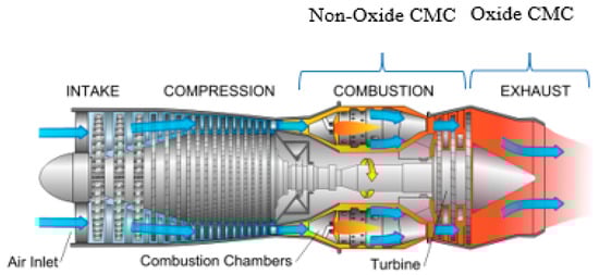
Figure 6.
Representation of CMC component parts in a gas turbine engine.
Until now, the CMCs used for aero-engine applications are limited to aluminosilicate or alumina/mullite CMCs from the oxide-CMCs and SiC/SiC, C/C, and C/SiC from the non-oxide-CMCs. The barriers associated with such limited use of CMCs include high ceramic matrix development costs, risks with scale-up and material capability uncertainty, and risks of ceramic fillers and reinforcements robustness, which leads to high costs for material qualification and material availability [181]. Furthermore, the aerospace industry has set strict material requirements and specifications that include the material’s mechanical, physical, thermal, and chemical properties, which advocate that for a material to be used, it needs to have high strength, stiffness, fatigue durability, damage tolerance, low density, high thermal stability, high corrosion, and oxide resistance [182]. More specifically, the most important aspects of mechanical and thermal results are the material’s elastic limit and stiffness from mechanical properties and thermal expansion coefficient and thermal conductivity.
The figures below demonstrate the comparison of the already classified oxide and non-oxide CMC materials from Section 4 and Section 5, respectively, according to the aerospace requirements for mechanical and thermal properties. The output of this comparison allows for drawing conclusions on the differences between the properties of the used CMCs in aerospace applications. The mechanical and thermal properties included in this analysis are compressive strength, specific stiffness, fatigue resistance, fracture toughness, maximum temperature, thermal conductivity, and thermal expansion coefficient. All these attributes play a role in the aero-engine material selection. For comparison, the properties of conventional superalloys used in aerospace applications are included as well. The values of the properties are sourced from the reviewed literature.
Figure 7 and Figure 8 compare the compressive strength and specific stiffness of the different CMC materials. Compressive strength allows for an estimation of the load a solid material can handle before fracture, and the specific stiffness allows for a weight to ratio comparison of the solid materials. Although such mechanical properties are not as important for aero-engines as for air structures, it is important to position CMCs compared with the competition. Both properties offer an estimation of the level at which the materials can withstand the maximum load with the lowest density. Figure 8 shows silicon carbide matrix composites outperform the rest of the CMCs and are at the same level as the conventional aero-engine superalloys used. With regards to the specific stiffness, all CMCs outperform the conventional superalloys, with titanium carbide matrix CMCs managing to have an almost eightfold higher performance than conventional superalloys.
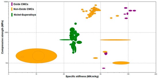
Figure 7.
Comparison of compressive strength vs. specific stiffness.
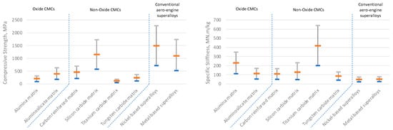
Figure 8.
(Left) Compressive strength and (right) specific stiffness of available CMCs and comparison with superalloys.
Figure 9 and Figure 10 compare the fatigue resistance and fracture toughness of the available oxide and non-oxide materials. Fatigue resistance shows the highest stress the materials can withstand for a specific amount of working cycle without breaking and fracture toughness allows for an estimation of how fast cracks propagate and become dangerous. Alumina matrix oxide CMCs outperform the rest of the CMCs and are at the same level as the conventional superalloys used in aero-engines. CMCs, on the other hand, have significantly lower fracture toughness than conventional superalloys; however, this is expected for any composite material. However, if the quality of the final component is closely monitored to avoid the development of any cracks, then this is not a critical parameter for aero-engine components.
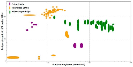
Figure 9.
Comparison of fatigue strength vs. fracture toughness of the available CMCs.
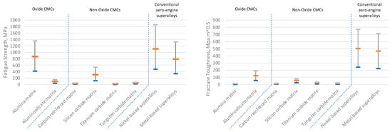
Figure 10.
(Left) Fatigue strength at 107 cycles and (right) fracture toughness of the available CMCs and comparison with superalloys.
As indicated by Boyer et al. [182], materials used in aero-engines need to control thermomechanical processing conditions to minimize material defects. Figure 11 and Figure 12 compare the thermal expansion coefficient against and thermal conductivity of the available oxide and non-oxide CMCs and the conventional superalloys used in aero-engines. Both thermal properties are highly considered for the selection of a material for high-temperature applications (e.g., aero-engine). The thermal expansion coefficient gives an estimation of the dimensional transformation of the materials when exposed to high temperatures and at constant pressure, whereas thermal conductivity shows the ability of a material to conduct and transfer heat. The lower the thermal expansion coefficient and thermal conductivity results, the more attractive material for high-temperature applications becomes. As can be seen from Figure 12, all CMCs outperform superalloys when it comes to the thermal expansion coefficient, indicating that structures composed of CMCs will offer higher thermal stability and rigidity. With regards the thermal conductivity, most CMCs perform at similar levels to conventional superalloys. Aluminosilicate matrix composites present the lowest thermal conductivity coefficient, whereas tungsten carbide matrix CMCs are at the other end of the spectrum. This indicates that the potential selection of tungsten carbide matrix CMCs for components might require additional consideration for cooling the components in order to dissipate the heat better (as an example, this could be achieved by using internal cooling channels). The literature review indicated that aluminosilicate CMCs, and more specifically Nextel 720 woven fabric, exhibit the lowest thermal conductivity and thermal expansion coefficient.
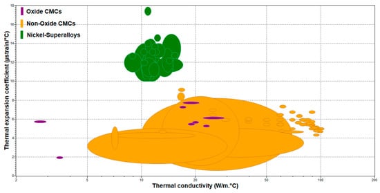
Figure 11.
Comparison of thermal expansion coefficient vs. thermal conductivity of the available CMCs.
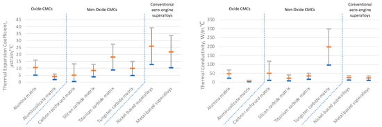
Figure 12.
(Left) Thermal expansion coefficient and (right) thermal conductivity of CMCs and comparison with superalloys.
Figure 13 and Figure 14 compare the maximum service temperature and thermal shock resistance of the available oxide and non-oxide CMCs with the conventional superalloys. Maximum service temperature allows for an estimation of the highest operating temperature material can be used without failing, and thermal shock resistance shows how much temperature change a material can handle without causing any interphase damage or even catastrophic failure. According to research, materials used in aero-engine applications require high thermal shock resistance due to the instant temperature changes. Aluminosilicate oxide matrices, and more specifically Nextel 720 woven fabric, have better overall results as they can withstand temperatures higher than 1000 °C and over 700 °C thermal shock resistance. On the other hand, carbon fiber-reinforced carbon matrix composites have the highest service temperature and the highest thermal shock resistance surpassing the performance of the superalloys used in aero-engines.
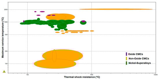
Figure 13.
Comparison of maximum service temperature vs. thermal shock resistance of available CMCs.
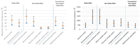
Figure 14.
Comparison of (left) maximum service temperature and (right) thermal shock resistance of CMCs.
7. Manufacturing Processes for CMCs
As highlighted in Section 6, CMCs exhibit mechanical and thermal properties comparable with, and in some cases, even better than, the conventional superalloys used in aero-engines. However, their adoption relies on other variables as well, such as the cost of development, industrialization, manufacturing, and the availability of manufacturing technologies and systems. In this section, the manufacturing capabilities and technologies associated with the fabrication of CMCs will be discussed.
Until recently, there has been a small number of manufactured CMC materials which mostly include carbon fibers embedded in a silicon carbide matrix fabricated with chemical vapor infiltration and some oxide-oxide aluminosilicate matrices combined with sintering and sol-gel infiltration process. As a result, there is a high demand for the fabrication of a variety of CMC components fabricated with efficient processes allowing for lower processing times, cost, and greater mechanical and thermal attributes. This is achieved with the embodiment of a wider range of ceramic materials apart from C/SiC or C/C composites, which can also be pre-impregnated with carbon/carbon materials and pre-ceramic polymer, processed with the already existing manufacturing processes. Research also indicates that no special interface is needed to fabricate low-cost CMC structures or implement prepreg when a separated fiber/matrix interphase is not required. These combinations of materials can include amorphous variations of Si-O-N-C, HfC, SiC, HfC, etc. Ceramic components are produced mainly from polymer infiltration pyrolysis (PIP), melt infiltration (MI), sintering processes, and chemical vapor infiltration (CVI) [183]. The typical methods used for CMC fabrication are summarized in Figure 15.
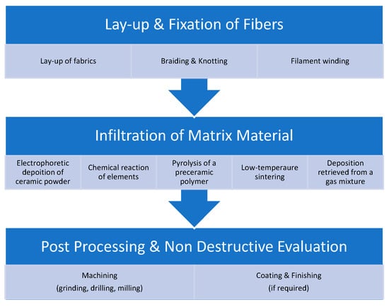
Figure 15.
Fabrication procedure steps for CMCs.
The processing can be grouped in a three-step series, which every CMC material goes through to achieve the needed mechanical, thermal, and physical properties [184]. The first step consists of a lay-up and fixation of the fibers, formed according to the required component geometry. The second step consists of the infiltration of the matrix material. This step includes five different procedures, which are needed to fill the ceramic matrix in between the fibers and the pre-form. These infiltration procedures are sintering at a significantly low temperature (1000–1200 °C), pyrolysis of a pre-ceramic polymer, chemical reaction of elements, deposition retrieved from a gas mixture, and finally, electrophoretic deposition of a ceramic powder [109,184,185].
Non-oxide CMCs are manufactured with deposition out of a gas mixture, pyrolysis of a preceramic polymer, or chemical reaction of elements. Oxide CMCs are manufactured by sintering or electrophoretic deposition of a ceramic powder [185,186]. The third and final step consists of machining and, if required, coating or impregnation of the intrinsic porosity [185]. In the following paragraphs, the most frequently used manufacturing processes will be reviewed.
7.1. Electrophoretic Deposition of a Ceramic Powder
During electrophoretic deposition (EPD), a stable deposit is created by charging particles in a liquid medium moving with an oppositely charged electrode and coagulating. This process has been mainly used for the fabrication of oxide CMC matrices and fibers, as it reduces the processing times and improves the control of green body microstructures [187,188]. The base material matrices used for this manufacturing process are aqueous or non-aqueous suspensions of ceramic particles and non-conductive NextelTM or conductive fibers such as SiC-Nicalon and carbon reinforcements [189,190]. For the manufacturing of non-conductive fibers, the fiber weave goes on the front of the deposition electrode, while the ceramic deposit is formed on the electrode and grows around and through the fiber [186,191].
Two alternative processes, based on EPD, have been developed and evaluated, where Al2O3 particles and NextelTM 720 fibers were used. The first processing method presented the infiltration of single fiber mats and subsequent lamination, which led to high-density composites but with a small amount of microstructural damage during sintering [192]. On the other hand, the second approach used simultaneous infiltration of a variety of fiber mats, exhibiting a homogeneous green microstructure with a high particle packing density, allowing for the fabrication of thick components (>10 mm thick) [193]. The EPD technique has been used in a variety of ceramic composite systems during the decades, such as laminated composites [194], composite coatings [195], whisker-reinforced composites [196], and functionally graded materials [197].
7.2. Matrix Deposition/Infiltration from a Gas Phase
Chemical vapor infiltration (CVI) is considered one of the most attractive manufacturing processes for creating fiber-reinforced CMCs [198]. In this process, the porous preform is added in a surrounding of a reactive gas mixture, which decomposes and yields a solid deposit that is concentrated in the pores of the preform when the mixture is thermally activated. This process allows for the creation of preform complex net shape components, at low temperatures, without occurring any damage to the textile structure, which results in controlling and modifying the microstructure of the final matrix [198]. CMCs such as SiC/SiC and C/C composites are fabricated using this process, allowing for excellent high temperature, strength, modulus of elasticity, creep, and corrosion resistance properties, in comparison with other unreinforced SiC composites [199].
There are several different CVI techniques developed for different composites, with the most well-known one being the isothermal one (I-CVI), used for non-oxide CMCs beginning with Cf/C and moving to SiCf/SiC composites. This process was initially created for the densification of refractory composites [109]. In recent decades, it has been used for the densification of Cf/C for aircraft brakes and SiCf/SiC for aerospace components [200]. Some of the most fabricated matrices with CVI are SiC, C, Si3N4, BN, Al2O3, B4C, TiC, and ZrO2.
I-CVI is introduced as thermal-gradient CVI (modified CVI) and is used for the manufacturing of large individual parts, such as rocket nozzles [201]. In this method, the preform is heated more uniformly due to the increase in thermal conductivity of the infiltrated preform [202,203]. The thermal gradient F-CVI deposition has been introduced as a replacement for the I-CVI while working on SiC and Si3N4 matrices with different porous preforms, where the mass transfers occurred by forced convection due to a pressure gradient [199]. Bussmann et al. researched the practicality of the manufacturing of SiC/SiC components by using the F-CVI process [204]. Furthermore, it has been researched that the infiltration times of the F-CVI process, reporting that the SiC matrix fabrication times were reduced even though the preforms were 2.5 mm thick [205].
Another alternative technique, called microwave-heated CVI (MW-CVI), is used for controlling the inverse temperature profile of a ceramic fiber preform while heating [205]. It can produce a controllable temperature profile inside a preform [206]. It allows the creation of a temperature gradient from the center of the preform to the outside layers, meaning that the deposition of the ceramic matrix occurs from the inside to the outside, without connecting to the sealing of the outer pores of the preform, that might cause any structural problems [207]. Research on scaling up this process and designing a pilot-scale reactor has been recently published [208].
Further research shows the evolution of an improved film boiling CVI process for manufacturing large-size Cf/C CMCs by using kerosene as a precursor. The result of this process was a composite produced with rapid CVI with a homogeneous microstructure and density that allowed for good feasibility of the film boiling CVI procedure for large components [209]. Rapid-CVI is particularly applied to C/C composites and is considered to have two different types of fabrication methods. The first method is called boiling film, in which the porous fiber preform is absorbed inside the liquid state precursors [210]. The second method is rapid vapor-phase densification, in which the porous preform is added to a furnace and is isothermally heated by a graphite tool, offering a forced flow to the precursor gas that exists beside the preform and the graphite tool [210].
7.3. Melt Infiltration
The melt infiltration process has been successfully used for the creation of reaction-bonded ceramics for ultra-high-temperature applications. C/SiC and SiC/SiC CMCs are mainly fabricated with this process, where Si melts are infiltrated in the porous carbon-based preforms for SiC to be formed [211]. MI produces a dense matrix in a shorter cycle time than other infiltration applications, although the needed temperatures are relatively high (up to 1414 °C) [212]. SiC fiber tows are coated with boron nitride fiber interface and silicon nitride coating. Both the unidirectional fiber and matrix types are created by using a filament winding process and have polymer binders along with commercial SiC and Cf powders. After the tape layup is finished, lamination occurs in a part preform, leading to pyrolysis. After the polymer is turned into carbon, densification of the pyrolyzed preform with SiC and melt infiltration occurs.
Research shows the fabrication of carbon fiber with SiC-ZrC matrix CMCs. This resulted in the creation of a SiC-ZrC matrix with the SiC matrix adjusting to the carbon film coating fibers, allowing for high bending strength, oxidation resistance, and better ablation resistance in oxyacetylene flame, better than the one that ZrC CMCs have [213].
Other research shows the fabrication of carbon fiber-reinforced C-SiC-Ti3SiC2 hybrid matrix composites by implementing TiC slurry and molten Si infiltration processes. This resulted in a successful CMC manufacturing process due to the use of high stability and low viscosity of TiC ball milling. The mechanical properties of the fabricated CMCs were increased with the conversion of TiC to Ti3SiC2. On the downside, the research demonstrated that the use of Ti3SiC2 grains in the CMC matrix led to fiber-matrix decohesion, intergranular cracking, and delamination [214].
7.4. Matrix Forming via Pyrolysis of C- & Si-Containing Polymers
Polymer infiltration pyrolysis is a low-cost fabrication process for SiC (from silicon-derived polymer precursors) reinforcements and nanoparticles CMCs and plays a key role in the oxidation resistance of the resulting composite [215]. There are several steps that the reinforcement fiber and base ceramic material must undergo to create an efficient composite [216]. The first step is to impregnate the reinforcing fibers with a resin and apply partial curing. In continuous, the preparation is shaped into a mold. The mold is combined with a flexible upper mold, pressed against the prepreg with atmospheric pressure (vacuum bag) or high air pressure (gas pressure bag), and turned into an autoclave [217]. Then the infiltration of the pre-ceramic polymer occurs while the preform is added into it, vacuum or pressed assisted. Subsequently, the pyrolytic decomposition of the preceramic polymer takes place in an Argon atmosphere at high temperatures, manufacturing the final material composition. Different atmospheres can be introduced into the pyrolysis, resulting in different matrices. After the final matrix is fabricated, the infiltration pyrolysis is repeated up to ten more times to minimize the porosity of the ceramic matrix.
The preceramic polymer field has been developed, producing the Si-C-N-O system, focusing exclusively on non-oxide ceramic fibers [218]. Further investigation on the fabrication of Grade Niclon SiC fiber and HI-Nicalon SiC fiber CMCs, with the PIP process, has been reported, indicating that these fiber-reinforced CMCs could be effectively used in high temperature (up to 1200 °C) structural applications for long periods [219]. Furthermore, it has been shown that pyrolysis can be performed between 1000–1200 °C under nitrogen flow. The effect of lower pyrolysis temperature, with higher ramp rates, by using SiC/SiC CMCs, has been researched. This allows for a cheaper industrial production cost; high residual porosity and microcracks occur due to the relative density and bending strength being lower. It was concluded that to achieve higher density, and the used preform must be evacuated before the polymer solution is added into the mix, which is not feasible to happen for the fabrication of large components [216].
7.5. Matrix Forming via Sol-Gel
Sol-Gel infiltration is a valuable fabrication method of CMCs, using fibrous preforms as the precursor materials, including better homogeneity, near-net shape fabrication, and low processing temperatures (<600 °C) [220]. Although, sol-gel needs to repeat the infiltration process several times, using intermediate heat treatment, to surpass the excessive shrinkage of the matrix while sintering and drying take place [221].
In sol-gel infiltration, a chemical precursor is hydrolyzed into a gel, then dried and fired to create a ceramic composition. The precursor materials come in the form of water, alcohols, and metal oxides to commercially stabilize colloids which include discrete ceramic particles. The hydrolysis reactions allow for an organometallic solution, including polymer- chains that have metallic ions and oxygen. The amorphous particles are formed from the solution, producing a rigid gel, which is continuously dried and fired to allow for the sintering and densification of the last ceramic part [222]. For a successful sol-gel infiltration process, the sol should include high ceramic content, low viscosity, and small particle size, which allows it to be processed at low (room) temperature for several hours [223].
Many attempts have been made to examine the effects of sol-gel processing parameters by using different types of oxide fiber preforms such as mullite, aluminosilicate, and zirconia [224]. The results indicated that sol-gel is mostly effective for the fabrication of near net shape CMCs by using discontinuous mullite fiber preforms but also can be applied in multiple infiltrations in other oxide fillers for the development of CMCs with pseudo ductile characteristics [221].
7.6. Matrix Forming via Sintering
Sintering and pyrolysis processes are used to fill a ceramic matrix in between fibers. More specifically, sintering can take place in an oxygen atmosphere, but temperature control and temperature uniformity in the furnace for heating and cooling allows for better results. Sintering for powdered materials occurs at high temperatures according to the application and atmosphere (oxidizing/non-oxidizing) that is being used [225].
The sintering process of powdered materials is created at elevated temperatures, occurring in an oxidizing environment. Automated powdered metal sintering furnaces allow for better reliability and operating costs. These automated systems include a preheat section, a heating section, and a cooling section [226].
There are various types of sintering techniques that allow for a similar outcome depending on the precursors used. These different types include diverse hot presses, hot-isostatic presses, pressureless sintering, microwave sintering, and SPS. Furthermore, research showed that long-lasting and high-temperature sintering allowed for the enlargement of the grain size, causing the number of micropores that emanated from the materials to decline in the mechanical properties [227].
SPS is the most preferred sintering technique for the densification of ceramic composites in comparison with conventional sintering. This is due to densification times being reduced (<15 min) and sustaining a comparatively small grain size, influencing the suppression of uncontrolled grain growth and eliminating porosity. This allows for better mechanical properties [228].
7.7. Matrix Forming via Chemical Reaction
Liquid Silicon Infiltration (LSI) process is created by combining processed C/C with melted silicon carbide fibers, allowing for the creation of thin-walled and lightweight CMC components. It is characterized as a three-step process, starting with the manufacturing of carbon fiber-reinforced polymer, followed by carbonization and finishing with liquid silicon infiltration [229]. More specifically, the first step consists of the manufacturing of the CFRP composites with polymer matrices with high carbon yield, which allows for conducting the pyrolysis of the green bodies in one attempt. The second step includes the treatment of the CFRP composites in an inert atmosphere/vacuum, with temperatures ranging from 900 to 1650 °C [230]. Then, the pyrolysis of the matrix allows for a volumetric construction of 50–60% of the original polymer, and if hindered, this leads to a lower shrinkage of the macroscopical composite, which is almost zero [231]. In addition, bidirectional reinforced composites and in-plane reinforcing fibers, such as woven fabrics, impede the shrinkage without interacting with the plane of the laminate [231,232]. Furthermore, the lower the fiber volume percentage and the higher the fiber/matrix bonding in the green body, the higher the transverse shrinkage of the composite. This results in providing C/C composites with an interconnecting pore structure that leads to a translaminar crack system, where the cracks showcase the open porosity of the composite material. After this step is completed, the third and final step is the capillary effect of this open porosity in between C/C laminate and low viscosity of melted silicon at 1420 °C, allowing for a quick composite filling. The continuous exothermic reaction of the C/C and liquid silicon results in silicon carbide encapsulated fiber bundles, offering an increase of 30–50% of the mass for the two-dimensional reinforcements. The final composite consists of three phases which include two-thirds of carbon, one-third of silicon carbide, and a small amount of unreacted silicon [229].
The LSI process allows for the compact bundles of short carbon fibers to remain intact while the infiltration process with liquid silicon takes place. This happens by creating a green body that includes short fiber bundles and a matrix of phenolic resin. Furthermore, the usage of polymeric precursors with high carbon yields allows for the formation of the characteristic microstructure of the porous C/C preform after the pyrolysis process takes place, leading to discrete translaminar capillary channels where the good penetration of the preform is achieved due to liquid infiltration. This offers the creation of stronger bonds between matrix and fibers and enhances the overall performance of the final composite material [230].
7.8. Selecting the Most Appropriate Manufacturing System
According to the literature presented in this section, the main fabrication processes used for CMCs include CVI, polymer infiltration, pyrolysis, and hot press sintering techniques. Polymer infiltration and pyrolysis are the most commonly used ones. The main aim is to be able to control the thermal and mechanical properties of the fabricated CMC, but several factors, such as the distribution of the final phase formed and the processing route applied from the synthesis of the composite, are very important aspects. These aspects can be manipulated from the correct choice of composite fabrication processes. Every process has different positive and negative attributes, as shown in Figure 16.
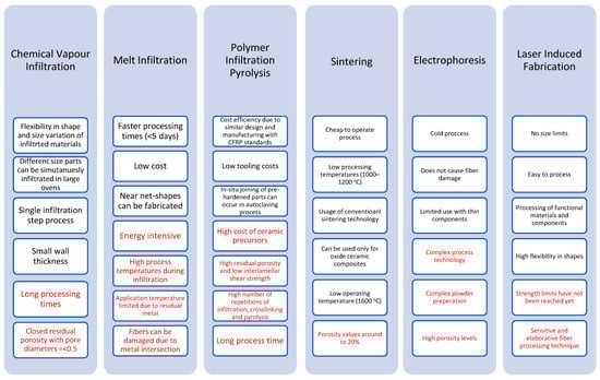
Figure 16.
Fabrication procedure steps for CMCs.
A major criterion is the price per unit volume of the ceramic matrix and fiber used, as well as the environmental impact of the material (going all the way back to the extraction of the constituting materials, their processing, and delivery to the CMC fabrication plant). This environmental impact can be quantified through the use of embodied energy, which accounts for the energy consumed by all manufacturing processes used. As can be seen in Figure 17, aluminosilicate CMCs have the highest embodied energy as they have some of the more complex material compositions. This indicates that the manufacturing process used to compose this type of CMCs (sol-gel infiltration, sintering) requires a lot of energy and time, increasing the final cost of the production of aluminosilicate-based applications. On the other hand, carbon matrix, alumina oxide, and silicon carbide CMCs have lower embodied energy, meaning that these materials are easier to be produced at larger production rates with lower overall costs and faster time scales. This is because their process materials have fewer complex compositions as they include smaller amounts of fibers and matrix materials.
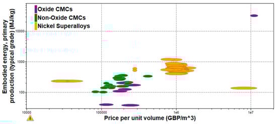
Figure 17.
Embodied energy and price per unit volume of CMCs.
It must be mentioned that manufacturing processes differ in processing time and processing stages before finalizing the finished material. As a result, the process runs at a higher cost and with longer times than other processes. For example, manufacturing processes that have more complex process technology and complex composite preparation, such as CVI and EPD, are more expensive to run. Although, as mentioned before, the more complex the material composition, the more embodied energy and electrical resistivity are spent. Hence it has been found that infiltration processes and, more specifically, PIP, CVI, and MI are less cost-efficient and more time-consuming, although their final composite outcome has very good mechanical and thermal properties [233]. This could also be justified by conducting a comparison of the price per unit volume against the price of the available oxide and non-oxide CMCs, which includes both the material production and manufacturing cost, allowing for an estimation of the final manufacturing procedure’s cost outcome. Aluminosilicates are the most expensive composites to produce from both oxide and non-oxide CMCs. On the other hand, alumina oxide composites are much more cost-effective to produce from the oxide CMCs allowing a wider range of materials submerged into the final matrix without having an excessive price increase in manufacturing processes. Finally, carbon matrix CMCs have the lowest production and manufacturing cost as they require the least amount of energy while being cost-effective to extract and purchase.
8. The Future of CMCs
The literature review on the available CMCs and the manufacturing processes that can be used for their fabrication can be used for a better insight into the future of such materials for aero-engine applications. Based on this literature review, a technology roadmap is provided in this section. CMC material properties allow them to be the solution in a variety of today’s material challenges in process industries, aerospace, power generation, transportation, and for military applications. These types of applications are essential in obtaining global competitiveness, minimizing environmental pollution, and decreasing overall energy consumption [234]. CMC prototypes and trial products become available to create test methods, classification systems, and unified terminology as well as reference materials for aero-engine applications, but the lack of design codes and their related databases have been limiting factors in obtaining approval to use more extensively CMCs in both rotary and stationary Aero-Engine applications [235].
Every step in Figure 18 requires significant effort and time, enabling full consensus to be developed for reaching maturity to allow characterizing the developed CMC. Continuous databases need to be created to produce property and performance data using acceptable standards. A wide variety of different information levels must be assigned in the database to proceed to the creation of design codes and life prediction models to be used in the unique design requirements and applications. After the design codes and life expectancy models are determined, regulatory approval is achieved and can be used in aero-engine applications.
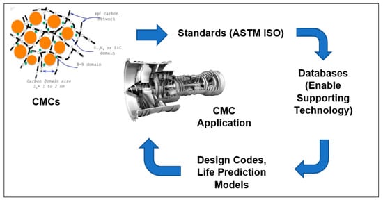
Figure 18.
Interrelation of standards, databases, life expectance models, and design codes of CMCs.
There are a few steps that, according to research, are required to take place for the CMC material to meet the expectations of end-users to develop a ceramic component for a specific application [234]. This is achieved by creating an RD&D approach, which considers these steps at the same time to achieve the CMC’s commercial success.
The development process steps (Figure 19), in addition to the R&D approach, are interrelated with the material database, producing data to use in material selection and providing analytical support design and life prediction models. Furthermore, the design and life prediction models improve the methods and analytical tools, providing greater efficient component design. After the design and life prediction models, the non-destructive evaluation is an improvement method allowing for low-cost component inspection and quality assurance. When the component passes the non-destructive evaluation, the fabrication optimization method takes place, increasing material reliability, manufacturing scale-up, and cost reduction. Finally, the demonstration stage takes place, verifying the CMC component viability with long-life testing in the final work environment of the product.
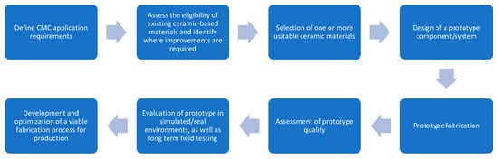
Figure 19.
CMC development process steps.
8.1. CMC Adoption Roadmap
Figure 20 presents the engineering challenges that must be addressed to increase the materials’ maturity and eventually allow for the adoption in aero-engine applications. The timeframe suggested is based on historical data obtained from the literature review until 2022, and forecasts are based on the reported pace of research. Solutions that can address these requirements can be based on introducing ceramic materials that incorporate a reinforcing phase (whiskers/long fibers) while they are fabricated into a ceramic matrix, allowing for the creation of a CMC material with superior properties. Some of the most common examples are silicon carbide fibers combined with silicon carbide matrix, and aluminum oxide fibers combined in aluminum oxide matrix [236]. Addressing these requirements (Figure 20) will create an understanding of the interaction of the composite constituents with each other and with their application environments. A repetition of composition selection, fabrication, testing, and post-testing will be required to assess their final performance to accomplish these actions. Furthermore, from the table above, a very important priority is the increase in CMC material lifetime. For a few decades, research has focused on progressively increasing the temperature capability, life, and design limit of the available CMCs, but so far, the solution has relied on prioritizing the research focus on fibers, fiber coatings, matrix chemistry, and environmental barrier coatings without focusing on prioritizing on manufacturing facilities for simulation environments and accelerated testing, which might allow the end-users for increased field and experimental testing, which could achieve a more successful result [237,238,239].
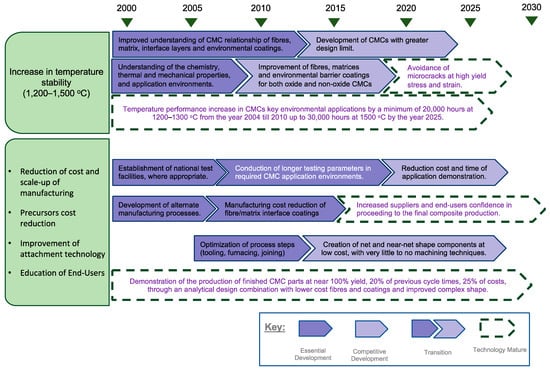
Figure 20.
CMC requirements needed to be met for wider adoption.
CMCs development aims to replace monolithic ceramics by achieving better mechanical and thermal properties. This would allow for the creation of more reliable components which can be used with a greater level of confidence, comparable to the confidence offered by metal components [240]. On the other hand, CMCs are in an early development stage, and further research is required before using them in a variety of applications.
The growth rate of advanced ceramics and, more specifically, composites was increased worldwide. Focusing on the commercialization of the next-generation ceramic matrix composites for future aerospace applications, water polymers, low-density ceramics, and nanofibers converted to SiC reinforcing fibers for increased toughness are being under development allowing for better maximum service temperatures [241,242]. If this outcome is achieved, it is expected from CMCs to grow at a 9.65% rate of value until the year 2026, including oxide/oxide, SiC/SiC, C/C, and C/SiC, according to the international market research results [243].
Figure 21 presents a roadmap for CMC materials, coating, and manufacturing processes for aero-engine applications. Similar to Figure 20, the timeframe suggested is based on historical data obtained from the literature review until 2022, and forecasts are based on the reported pace of research.
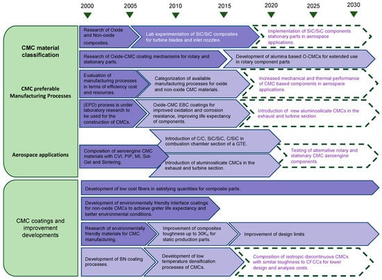
Figure 21.
CMC materials, coatings, and manufacturing processes for aero-engine applications Roadmap (the same key as Figure 20 applies).
A critical parameter for high thermal efficiency aero-engines is the high overall pressure ratio that drives high turbine flow path temperatures. The need for developing and applying advanced material technologies, which allow for improved high temperatures, is very high. The introduction of CMC materials in these types of applications allows for a small fuel burn and an additional 50% weight reduction percentage in turbine component weight [244]. Research and development of CMC materials have been ongoing for more than three decades, with aerospace industries, such as GE Aviation and Rolls Royce, investing and applying these materials in process technologies as well as in manufacturing scale-up and supply chain. Some of the most known CMC applications were the construction of shrouds in commercial leap engines used in Boeing, Airbus, and COMAC aircraft engineering. Furthermore, CMC materials have been used for applications in the hot section of a gas turbine engine for the combustor inner and outer liner, the HPT stage 1 and 2 shrouds, and nozzles during the years 2016 and 2020 [245]. Some of the most common CMC materials used for those types of applications are SiC/SiC, C/SiC, and C/C components produced with melt infiltration process, chemical vapor infiltrations, and pyrolysis. These manufacturing processes allowed for the creation of a denser matrix, allowing a relatively uniform distribution of separately coated filament fibers. In addition, new CMC material facilities have been established since 2019, producing SiC fiber CMC parts for jet engines and advanced ceramic coating made from oxide layers [246].
Continuous fiber composite ceramic materials are CMC materials made from high-strength ceramic fibers in a ceramic matrix, where the interface coating between the fibers and the matrix protects the surface of the composite from degradation. The composition methods and the available materials for creating a variety of this type of CMCs are very limited due to the lack of understanding of the relationship of fibers, matrix, and coatings, as well as the properties and application environments in which these materials can operate. Thus, more failure models and mechanisms must be created and explored to optimize CMC materials [247]. Although, prior to the development of life expectancy models, extensive CMC fabrication and testing must be undertaken to have a better understanding of the micromechanics of CMCs when exposed to high-stress and temperature application environments. For the testing of the composite combinations, non-destructive evaluation techniques are required for in-line process control and post-process testing to check for incipient failure and the remaining life of the composite [248].
For composite materials to pass the non-destructive evaluation techniques, the optimization of fabrication processes must be achieved. CFFC materials are highly reliable and can avoid catastrophic failure due to the reproducibility of their fabrication processes and the low cost of fibers and composite matrix materials. More materials should be tested and processed to create CFFCs that will meet the aerospace application needs, allowing also for fabrication scale-up and cost reduction.
Figure 22 shows that CMCs outperform conventional aero-engine materials, such as metal and polymer matrix composites (MMC, PMC). They also have overall better mechanical and thermal properties than metal, polymer, and natural matrix composites, with the maximum service temperature values being significantly higher (≤500 °C). CMCs that are able to operate between 1000–1500 °C are used for oxidation protection layer in aero-engine applications. These materials belong mostly to the alumina oxide and aluminosilicate CMC material families. On the other hand, materials that surpass 1500 °C are mainly used as thermal insulation layers protecting the components used mainly in the hot section of a turbine engine. These CMCs are mainly SiC/SiC, C/C, C/SiC composites as well as alumina oxide matrices (Al2O3/B4C, AlTiO2, Al2O3/TiC). Furthermore, the use of Oxide CMCs in exhaust nozzle applications has shown improvement in component durability against titanium alloys, allowing for lighter weight and equal durability.
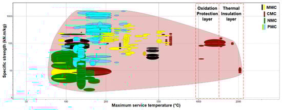
Figure 22.
CMC material performance against other composite matrices.
A great effort has been made regarding manufacturing and design processes for composite materials, where many manufacturing steps (lay-up, vacuum bagging, etc.) have been updated with different manufacturing methods (CVI, PIP, MI, Sol-Gel, etc.) where manual labor cost is avoided, and further cost saving have been achieved [249]. Composite components are being fabricated and designed for affordable and robust manufacturing. Chemical vapor infiltration technology is the most used process but is very time-consuming and expensive to operate, although its processes are very critical for the fabrication of CMC materials [250].
8.2. Technology Considerations
It has been found from the early 90s that lower-cost CMCs are worth developing for achieving better service temperatures, resulting in a multi-attribute utility better than that of superalloys for usage in exhaust ducts. The main reason was the need for improvement of the superalloys manufacturing techniques, achieving greater cost reduction results than other techniques, such as directional solidification and single-crystal casting [251]. Some of the first manufacturing techniques developed for the creation of more cost-effective materials were slurry infiltration and chemical vapor infiltration.
According to the literature, a third of the aerospace technological contribution has been spent on turbine inlet temperature (TIT) material improvement and, more specifically, nickel-based superalloys created with directional solidification and single-crystal technology [251,252]. The rest of the aerospace technological contribution was created for the introduction of internal cooling passage for turbine blades, vanes, and cooling technology advancement. In more recent years, research has shown that CMC materials exceed the thermal efficiency and power output required for turbine inlet temperature making them suitable to be applied in both rotary (nozzles, vanes, turbine blades) and stationary turbine engine parts [253]. Hence, aerospace companies have started using these types of manufacturing techniques for the creation of CMC components in both cold and hot sections of the gas turbine engine. Although it must be said that the commercialization of CMC materials requires more effort as some of the most common manufacturing procedures, cost a lot more than other types of superalloy composition techniques, such as chemical vapor infiltration (CVI) and polymer infiltration and pyrolysis process [254,255].
The commercialization of CMCs is in progress. The aerospace industry requires such materials, which will increase the life expectancy of the components used in turbine engines as well as other aero-engine parts, as well as lower the manufacturing cost and the environmental impact. For these steps to be accomplished, the literature suggests the utilization of R&D methods, which are needed for understanding the interactions of the composite constituents with one another and the application environments in which these composites are applied. To achieve that, iteration of composite material selection, manufacturing processes, testing, and post-test evaluation measures must take place to assess better material performance. The R&D methods also need to be linked with material characterization efforts, improving design and life prediction tools to establish standards and material databases (Figure 23 and Figure 24).
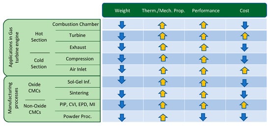
Figure 23.
Technology indicators (arrows indicating trends).
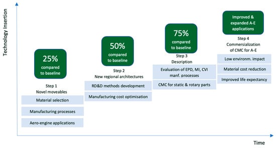
Figure 24.
Technology staircase.
9. Outcome
Ceramic-composite matrix (CMC) materials are separated into two base material categories. These categories include oxide and non-oxide ceramic composite materials. Oxide CMCs include alumina and aluminosilicate base matrices, whereas non-oxide CMCs include carbon, silicon carbide, titanium carbide, and tungsten carbide base matrices. Each one of these CMCs has different mechanical and thermal properties, which are considered the crucial factor for selecting the correct material for the needed applications.
The main difference between oxide and non-oxide CMCs is that oxide CMCs have greater creep and oxidation resistance properties when exposed to ultra-high temperatures. This occurs because oxide CMCs are predisposed to oxidation and creep even though their mechanical properties can withstand the amounts of pressure that are applied at those temperatures. Moreover, oxide CMC materials are mainly used for high-temperature structural applications, with the most common base matrix being alumina oxide. According to the literature, alumina oxide CMCs are being used and tested often in aero engine applications where the combination of silica and mullite can also be used as filler or reinforcements, enhancing the overall composite performance outcome. Non-oxide CMCs are also known to be used in a similar type of aero-engine applications long before the implementation of oxide CMCs, with silicon carbide and carbon being the most used type of reinforcement or base matrix materials.
A very important aspect of the development of a CMC component is the selection of the correct manufacturing process and processing steps, which will allow for a properly manufactured component without any microcracks, and which will not lead the material to creep and oxidation over a certain period, as well as a catastrophic failure. Manufacturing processes are also chosen from the compositional type of the material; for example, sintering and sol-gel processes are mainly used for the creation of oxide CMCs due to the oxidizing atmospheres in which the ceramic particles are exposed. In continuous, some of the most famous manufacturing techniques regarding high-temperature CMCs are the chemical vapor infiltration and pyrolysis processes. In this type of process, SiC/SiC and C/C are mostly created for aero-engine applications as they have been proven to be the safest option for the creation of a component without microcracks and are able to resist high pressure and temperatures without falling apart and have a greater and longer life cycle.
The combination of the correct manufacturing process, in addition to the correct combination of base matrix and filler/reinforcements, leads to a CMC composite with very good mechanical and thermal properties, allowing it to be used in a wide range of applications, according to the needs and requirements of every sector, for example, the aerospace application requires low thermal expansion coefficient and thermal conductivity, as well as high hardness and stress and strain values.
The present research focused on the classification of the available oxide and non-oxide CMC materials, their manufacturing processes, and available applications. Subsequently, a comparison of the mechanical and thermal properties of the classified CMC program allowed for a closer estimation of the chosen mechanical and thermal values of these materials.
The roadmap presented several important development goals regarding ceramic matrix composites usage in aerospace and turbine engine applications. They can be separated into different research groups, which allow for sustainable development and growth of CMC materials in the aerospace industry. These groups include novel ceramics with greater and more innovative properties, enhanced processing technology, and high-performance rotary and static components for aerospace applications. Furthermore, these development goals have been researched and processed since the early 90s, and their progress completion is estimated until the year 2030, according to the literature.
For these goals to be achieved, multi-disciplined approaches and techniques are required to enhance the CMC interphases and leadership from the industrial side. These techniques include small and large improvements that are needed for CMC fabrication processes cost reduction, as well as allowing for greater environmental impact and life expectancy. Currently, CMCs are considered for a very small number of high-cost applications due to the high price of the raw material supply, fabrication, and inspection methods. By lowering the cost of CMCs, a great benefit from longer life and higher reliability applications than metals and monolithic ceramics can be achieved. This can be achieved by putting more effort into researching the progressive increase in temperature capability, the design limit, and the life of ceramic base material and reinforcement fibers. For the achievement of these requirements, environmental barrier coatings, as well as upgraded fabrication and testing techniques, will be needed. A critical part of these accomplishments would be succeeded by creating facilities for simulated and faster testing established by stakeholders/partners. This development, though high risk, could lead to high payoffs in the near term for aerospace applications.
As a result, more multidisciplinary approaches and R&D collaborations will be necessary, including contributions, interfaces, and industry leadership. There are numerous “modest” and “major” breakthrough innovations that are needed in order to provide the anticipated improvement at all levels, from ceramic materials to applications, but these are rather extensive to detail here. It is crucial to realize that for changes and innovations to be truly effective, the entire value-added chain must be taken into account. Advanced ceramics have a tremendous amount of innovation potential, but to fully realize this potential along the entire value-added chain, significant efforts from both the academic and industrial sectors are needed.
All in all, despite already having a plethora of uses, CMCs have not yet reached their full potential. The obstacles in the medium and long term, particularly in aeronautics and aerospace applications, will be such that the use of custom materials will necessitate a significant R&D investment. Utilizing a suitable interface that intends to meet a set of requirements, various matrices and fibers will be used. In general, CMCs are heterogeneous composite systems where heterogeneity is defined by size, shape, geographic distribution, and various constituent properties. It is probably found in a variety of solid phases, including fibers, aggregates, and hard inclusions.
Reliable modeling and simulation tools must be obtainable from the beginning to accurately predict structural behavior at multiple scales (nano/micro/meso and macro) and time scales (short, medium, and long-term), as well as to control the effectiveness (mechanical, thermal, chemical, physical, and fire) characteristics of interest in advanced structures. This will hasten the creation of new types of CMCs and MMCs. For more realistic process simulation, more sophisticated multiphysical and mathematical theoretical models are also required. Following the definition of the requirements, it is necessary to develop new numerical approaches for products and processes that will identify the suitable composite system performance, the appropriate material production roadmap, and the processing research methods to achieve the needed “structural” behavior.
Author Contributions
Conceptualization, G.K. and K.S.; methodology, G.K. and K.S.; formal analysis, G.K.; resources, K.S.; writing—original draft preparation, G.K.; writing—review and editing, G.K. and K.S.; supervision, K.S.; funding acquisition, K.S. All authors have read and agreed to the published version of the manuscript.
Funding
The research presented in the present paper has received funding from the Clean Sky 2 Joint Undertaking (JU) under grant agreement No 886840. The JU receives support from the European Union’s Horizon 2020 research and innovation programme and the Clean Sky 2 JU members other than the Union.
Institutional Review Board Statement
Not applicable.
Informed Consent Statement
Not applicable.
Data Availability Statement
Data is contained within the article.
Conflicts of Interest
The authors declare no conflict of interest. The funders had no role in the design of the study; in the collection, analyses, or interpretation of data; in the writing of the manuscript; or in the decision to publish the results.
References
- Guglielmi, P.; Nunes, G.; Hablitzel, M.; Hotza, D.; Janssen, R. Production of Oxide Ceramic Matrix Composites by a Prepreg Technique. Mater. Sci. Forum 2012, 727–728, 556–561. [Google Scholar] [CrossRef]
- Rudinger, A.; Noth, A.; Pritzkow, W. Oxide Ceramic Matrix Composites-Manufacturing, Machining, Properties, and Industrial Applications. Technol. Insights Ceram. Appl. 2015, 23, 347–362. [Google Scholar]
- Grigorev, S.N.; Fedorov, S.V.; Hamdy, K. Materials, properties, manufacturing methods and cutting performance of innovative ceramic cutting tools—A review. Manuf. Revolut. 2019, 6, 1–27. [Google Scholar] [CrossRef]
- Zoli, L.; Vinci, A.; Galizia, P.; Melandri, C.; Sciti, D. On the thermal shock resistance and mechanical properties of novel unidirectional UHTCMCs for extreme environments. Sci. Rep. 2018, 8, 9148. [Google Scholar] [CrossRef] [PubMed]
- Pritzkow, W.E.; Almeida, R.S.; Mateus, L.B.; Tushtev, K.; Rezwan, K. All-oxide ceramic matrix composites (OCMC) based on low-cost 3M Nextel™ 610 fabrics. J. Eur. Ceram. Soc. 2020, 41, 3177–3187. [Google Scholar] [CrossRef]
- Krenkel, W. Ceramic Matrix Composites: Fiber Reinforced Ceramics and Their Applications; John Wiley & Sons: Hoboken, NJ, USA, 2008; Volume 102, pp. 420–431. [Google Scholar]
- Vijaya, R.B.; Elanchezhian, C.; Jaivignesh, M.; Rajesh, S.; Parswajinan, C.; Siddique, A. Evaluation of mechanical properties of aluminum alloy–alumina–boron carbide metal matrix composites. Mater. Des. 2014, 58, 332–338. [Google Scholar] [CrossRef]
- Diaz, O.G.; Luna, G.G.; Liao, Z.; Axinte, D. The new challenges of machining Ceramic Matrix Composites (CMCs): Review of surface integrity. Int. J. Mach. Tools Manuf. 2019, 139, 3–30. [Google Scholar]
- Mungiguerra, S.; Martino, G.D.; Savino, R. Ultra-High-Temperature Ceramic Matrix Composites in hybrid rocket propulsion environment. AIAA Propuls. Energy Forum 2018, 15, 129–135. [Google Scholar]
- Hickman, R.; Mc Kechnie, T.; Agarwal, A. Net shape fabrication of high-temperature materials for rocket engine components. In Proceedings of the 37th Joint Propulsion Conference and Exhibit, Salt Lake City, UT, USA, 8–11 July 2001; Volume 31, p. 3435. [Google Scholar]
- Pandey, V.K. Fracture Behavior of Aluminum/Alumina and Aluminum/Boron Carbide Functionally Graded Materials. Ph.D. Thesis, Indian Institute of Technology Delhi (IITD), New Delhi, India, 2019; pp. 247–254. [Google Scholar]
- Glass, D. Ceramic matrix composite (CMC) thermal protection systems (TPS) and hot structures for hypersonic vehicles. In Proceedings of the 15th AIAA International Space Planes and Hypersonic Systems and Technologies Conference, Dayton, OH, USA, 28 April–1 May 2008. [Google Scholar]
- Brennan, J.J. Interfacial characterization of a slurry-cast melt-infiltrated SiC/SiC ceramic-matrix composite. Acta Mater. 2000, 48, 4619–4628. [Google Scholar] [CrossRef]
- Hillig, W.B. Melt Infiltration Approach to Ceramic Matrix Composites. J. Am. Ceram. Soc. 2005, 71, 96–99. [Google Scholar] [CrossRef]
- Chae, K.; Chun, D.; Kim, D.; Bai, Y.; Eun, K.J. Microstructural Evolution During the Infiltration Treatment of Titanium Carbide-Iron Composite. Am. Ceram. Soc. 1990, 73, 1979–1987. [Google Scholar] [CrossRef]
- Krstic, Z.; Krstic, V.D. Silicon nitride: The engineering material of the future. J. Mater. Sci. 2011, 47, 535–552. [Google Scholar] [CrossRef]
- Han, W.; Li, Y.; Chen, G.; Yang, Q. Effect of sintering additive composition on microstructure and mechanical properties of silicon nitride. Mater. Sci. Eng. A 2017, 700, 19–24. [Google Scholar] [CrossRef]
- Volkmann, E.; Tushtev, K.; Koch, D.; Wilhelmi, C.; Goring, J.; Rezwan, K. Assessment of three oxide/oxide ceramic matrix composites: Mechanical performance and effects of heat treatments. Compos. Part A Appl. Sci. Manuf. 2015, 68, 19–28. [Google Scholar] [CrossRef]
- Wilson, D.M.; Visser, L.R. High-performance oxide fibers for metal and ceramic composites. Compos.-Part A Appl. Sci. Manuf. 2013, 32, 1143–1153. [Google Scholar] [CrossRef]
- Jefferson, G.; Keller, K.A.; Hay, R.S.; Kerans, R.J. Oxide/oxide composites with fiber coatings. Ceram. Matrix Compos. 2008, 8, 187–204. [Google Scholar]
- Keller, K.; Jefferson, K.G.; Kerans, R. Oxide-oxide composites. In Handbook of Ceramic Composites; Bansal, N., Ed.; Kluwer Academic Publishers: Boston, MA, USA, 2005; Volume 32, pp. 377–421. [Google Scholar]
- Kaya, C.; Kaya, F.; Butler, E.G.; Boccaccini, A.R.; Chawla, K.K. Development and characterization of high-density oxide fiber-reinforced oxide ceramic matrix composites with improved mechanical properties. J. Eur. Ceram. Soc. 2009, 9, 1631–1639. [Google Scholar] [CrossRef]
- Chawla, K.K. Ceramic Matrix Composite Materials Interface. In Ceramic Matrix Composites, 2nd ed.; Chawla, K.K., Ed.; Springer Science & Business Media: Boston, MA, USA, 2003; Volume 12, pp. 139–167. [Google Scholar]
- Park, S.J.; Seo, M.K. Element and Processing. Interface Sci. Technol. 2011, 18, 431–499. [Google Scholar]
- Pelaez, M.; Nolan, N.T.; Pillai, S.C.; Seery, M.K.; Falaras, P.; Kontos, A.G.; Dunlop, P.S.; Hamilton, J.W.; Byrne, J.A.; O’shea, K.; et al. A review on the visible light active titanium dioxide photocatalysts for environmental applications. Appl. Catal. B Environ. 2012, 125, 331–349. [Google Scholar] [CrossRef]
- Wanga, L.; Liua, W.; Golub, J.; Zhanga, Q.; Zhou, F.; Wanga, Y.; Ruiqing, C. Study on the wear resistance of graphene modified nanostructured Al2O3/TiO2 coatings. Appl. Surf. Sci. 2019, 492, 272–279. [Google Scholar] [CrossRef]
- Poges, S.; Monteleone, C.; Petroski, K.; Richards, G.; Suib, S.L. Preparation, and characterization of an oxide-oxide continuous fiber-reinforced ceramic matrix composite with a zinc oxide interphase. Ceram. Int. 2017, 43, 17121–17127. [Google Scholar] [CrossRef]
- Aviation, G.E. GE Successfully Tests World’s First Rotating Ceramic Matrix Composite Material for Next-Gen Combat Engine. 2015. Available online: https://www.geaerospace.com/press-release/military-engines/ge-successfully-tests-worlds-first-rotating-ceramic-matrix-composite (accessed on 31 December 2022).
- Parlier, M.; Ritti, M.; Jankowiak, A. Potential and Perspectives for Oxide/Oxide Composites. Aerosp. Lab 2011, 3, 1–12. [Google Scholar]
- Tye, A.; Lewis, M.H. Evaluation of novel interphases for oxide/oxide ceramic matrix composites. Br. Ceram. Trans. 1999, 98, 286–290. [Google Scholar] [CrossRef]
- Baldus, H.; Jansen, M. Novel high-performance ceramics—amorphous inorganic networks from molecular precursors. Angew. Chem. Int. Ed. 1997, 36, 328–343. [Google Scholar] [CrossRef]
- Cavdar, U.; Altintas, A.; Karaca, B. In-situ compaction and sintering of Al2O3-B4C composites by using a High-Frequency Induction System. Met. Mater. 2018, 56, 177–181. [Google Scholar] [CrossRef]
- Lin, X.; Ownby, P. Pressureless sintering of B4C whisker reinforced Al2O3 matrix composites. J. Mater. Sci. 2000, 35, 411–418. [Google Scholar] [CrossRef]
- Datye, A.; Koneti, S.; Gomes, G.; Wu, K.-H.; Lin, H.-T. Synthesis and characterization of aluminum oxide-boron carbide coatings by air plasma spraying. Ceram. Int. 2010, 36, 1517–1522. [Google Scholar] [CrossRef]
- Hamid, A.; Hadian, M.; Alizadeh, A. Processing and Mechanical Properties of Boron Carbide–Titanium Diboride Ceramic Matrix Composites. Appl. Compos. Mater. 2006, 13, 191–198. [Google Scholar]
- Badica, P.; Grasso, S.; Borodianska, H.; Xie, S.S.; Li, P.; Tatarko, P.; Reece, M.J.; Sakka, Y.; Vasylkiv, O. Tough anf dense boron carbide obtained by high-pressure (300 MPa) and low temperature (1600 °C) spark plasma sintering. J. Ceram. Soc. Jpn 2014, 122, 271–275. [Google Scholar] [CrossRef]
- Vozarov, M.; Neubauer, E.; Baca, L.; Kitzmantel, M.; Feranc, J.; Trembosov, V. Preparation of fully dense boron carbide ceramics by Fused Filament Fabrication (FFF). J. Eur. Ceram. Soc. 2023, 43, 1751–1761. [Google Scholar] [CrossRef]
- Toptan, F.; Kilicarslan, A.; Karaaslan, A.; Cigdem, M.; Kerti, I. Processing and microstructural characterization of AA 1070 and AA 6063 matrix B4Cp reinforced composites. Mater. Des. 2010, 31, 87–91. [Google Scholar] [CrossRef]
- Kim, H.W.; Koh, Y.H.; Kim, H.E. Densification, and mechanical properties of B4C with Al2O3 as a sintering additive. J. Am. Ceram. Soc. 2000, 83, 2363–2365. [Google Scholar]
- Sharma, P.; Sharma, S.; Khanduja, D. Production, and some properties of Si3N4 reinforced aluminum alloy composites. J. Asian Ceram. Soc. 2015, 3, 352–359. [Google Scholar] [CrossRef]
- Ramesh, C.; Keshavamurthy, R.; Channabasappa, B.H. Microstructure and mechanical properties of Ni-P coated Si3N4 reinforced Al6061 composites. Mater. Sci. Eng. A 2009, 502, 99–106. [Google Scholar] [CrossRef]
- Layden, G.K. Process Development for Pressure-Less Sintering of SiAlON Ceramic Components; Final Report, Contract N00019-75-0232; Naval Air System Command: Patuxent River, MD, USA, 1976. [Google Scholar]
- Gauckler, L.J.; Lukas, H.L.; Petzow, A.G. Contribution to the Phase Diagram Si3N4-AlN-Al2O3-SiO2. J. Am. Ceram. Soc. 1975, 58, 346–347. [Google Scholar] [CrossRef]
- Yeh, H.C.; Sanders, W.A.; Fiyalko, J.L. Silicon nitride-aluminum oxide solid solution (SiAION) formation and densification by pressure sinterin. Report no. E-8317; NASA Technical Memorandum, National Aeronautics and Space Administration: Washington, DC, USA, 1975. [Google Scholar]
- Lange, F.F. Fabrication and Properties of Silicon Cbihpounds-Task I. Fabrication Microstructure and Selected Properties of SiAlON Compositions; Westinghouse Research Labs.: Large, PA, USA, 1974. [Google Scholar]
- Crandall, W.B.; Hed, A.Z.; Shipley, L.E. Preparation and Evaluation of SiAlON; Final Report ARL-TR-74-0099; Aerospace Research Laboratory, Air Force Systems Command: Springfiel, VA, USA, 1974. [Google Scholar]
- Hisaichi, O.; Shoju, M.; Masakazu, O.; Kaoru, M.; Tadashi, S. Potential application of ceramic matrix composites to aero-engine components. Compos. Part A 1999, 30, 489–496. [Google Scholar]
- Lee, S.M. (Ed.) Handbook of Composite Reinforcements; VCH: Cambridge, UK, 1993. [Google Scholar]
- Hariharasakthisudhan, P.; Swaminathan, J. Characterizing the Compression Behavior of Al2O3/Si3N4 Nano-Sized Particulate Reinforced Ceramic Matrix Composites. Indian J. Sci. Technol. 2016, 9, 42. [Google Scholar] [CrossRef]
- Lee, C.S. Novel Joining of Dissimilar Ceramics in the Si3N4-Al2O3 System Using Polytypoid Functional Gradients. Acta Mater. 2001, 49, 3775–3780. [Google Scholar] [CrossRef]
- Jimoh, A. Calculate-Reinforcement of Titanium Matrix Composites with Borides, Materials Sciences and Applications. 2010. Available online: https://core.ac.uk/download/pdf/39668225.pdf (accessed on 21 February 2023).
- Boatemaa, L.; Brouwer, J.C.; Zwaag, S.; Sloof, W. The effect of the TiC particle size on the preferred oxidation temperature for self-healing of oxide ceramic matrix materials. Ceram. J. Mater. Sci. 2018, 53, 5973–5986. [Google Scholar] [CrossRef]
- Cai, K.; Axen, N.; Manyatsa, R. Preparation, Microstructures and Properties of Al2O3-TiC Composites. Ceram. Int. 2002, 28, 217–222. [Google Scholar] [CrossRef]
- Rocha-Rangel, E.; Hernández-Silva, D.; Terrés-Rojas, E.; Martínez-Franco, E. Alumina-based composites are strengthened with titanium and titanium carbide dispersions. J. Silic. Based Compos. Mater. 2010, 62, 75–78. [Google Scholar] [CrossRef]
- Sarkar, P.; Datta, S.; Nicholson, P.S. A functionally graded ceramic/ceramic and metal/ceramic composites by electrophoretic deposition. Compos. Part B-Eng. 2003, 28, 49–56. [Google Scholar] [CrossRef]
- Yoshioka, S.; Boatemaa, L.; van der Zwaag, S.; Nakao, W.; Sloof, W.G. On the use of TiC as high-temperature healing particles in alumina-based composites. J. Eur. Ceram. Soc. 2016, 36, 24–35. [Google Scholar] [CrossRef]
- Refugio-García, E.; Hernández-Silva, D.; Terrés-Rojas, E.; Rodríguez-García, J.A.; Rocha-Rangel, E. Microstructure of Alumina-Matrix Composites Reinforced with Nanometric Titanium and Titanium Carbide Dispersions. Mater. Res. 2012, 15, 898–902. [Google Scholar] [CrossRef][Green Version]
- Leyens, C.; Hausmann, J.; Kumpfert, J. Continuous Fiber Reinforced Titanium Matrix Composites: Fabrication, Properties, and Applications. Adv. Eng. Mater. 2003, 5, 399–410. [Google Scholar] [CrossRef]
- Das, R.; Ambardekar, V.; Pratim, B.P. Titanium Dioxide and Its Applications in Mechanical, Electrical, Optical, and Biomedical Fields. In Titanium Dioxide-Advances and Applications; InTech Open: Rijeka, Croatia, 2022. [Google Scholar] [CrossRef]
- Kim, I.J.; Gauckler, L. Excellent Thermal Shock Resistant Materials with low Thermal Expansion Coefficients. J. Ceram. Process. Res. 2008, 9, 240–245. [Google Scholar]
- Ulvi Gezici, L.; Gul, B.; Çavdar, U. The mechanical and tribological characteristics of Aluminum-Titanium dioxide composites. Rev. Metal. 2018, 54, 121–142. [Google Scholar] [CrossRef]
- Forero-Duran, M.; Dulce-Moreno, H.J.; Ferrer-Pacheco, M.; Vargas-Galvis, F. Wear and corrosion behaviour of Al2O3-TiO2 coatings produced by flame thermal projection. J. Phys. 2017, 935, 2–5. [Google Scholar] [CrossRef]
- Djendel, M.; Allaoui, O.; Boubaaya, R. Characterization of Alumina-Titania Coatings Produced by Atmospheric Plasma Spraying on 304 SS Steel. Acta Phys. Pol. A 2017, 132, 538–540. [Google Scholar] [CrossRef]
- Thomas, H.A.J.; Stevens, R. Aluminium Titanate—A Literature Review—Part 1: Microcracking Phenomena. Br. Ceram. Trans. J. 1989, 88, 144–151. [Google Scholar]
- Chengxin, Z.; Feng, C.; Yang, X.; Zhihang, P. Thermal shock resistance of Al2O3/SiO2 composites by sol-gel. Ceram. Int. 2019, 45, 11270–11274. [Google Scholar] [CrossRef]
- Anggono, J. Mullite Ceramics: Its properties, structure, and synthesis. J. Tek. Mersin 2005, 7, 1–10. [Google Scholar]
- Takada, H.; Nakahira, A.; Ueda, S.; Niihara, K.; Ohnishi, H. Improvement of mechanical properties of natural mullite/SiC nanocomposites. J. Jpn. Soc. 1991, 38, 348–351. [Google Scholar]
- Cui, K.; Zhang, Y.; Fu, T.; Wang, J.; Zhang, X. Toughening Mechanism of Mullite Matrix Composites: A Review. Coatings 2020, 10, 672. [Google Scholar] [CrossRef]
- Chauhan, S.; Kumar, A.; Singh, I.; Kumar, P. Effect of Fly Ash Content on Friction and Dry Sliding Wear Behavior of Glass Fiber Reinforced Polymer Composites-A Taguchi Approach. J. Miner. Mater. Charact. Eng. 2010, 9, 365–387. [Google Scholar] [CrossRef]
- Manu, S.; Rajan, T.P.D.; Pai, B.C. Structure and properties of squeeze infiltrated zirconia grade-aluminosilicate short fiber reinforced aluminum composites. J. Alloy. Compd. 2016, 688, 135. [Google Scholar]
- Garshin, A.P.; Kulik, V.I.; Matveev, S.; Nilov, A.S. Contemporary technology for preparing fiber-reinforced composite materials with a ceramic refractory matrix (review). Refract. Ind. Ceram. 2017, 58, 148–161. [Google Scholar] [CrossRef]
- Li, B.; Chen, H.; Chen, J.; Yan, M.; Hou, X.; Li, Y. Improvement of thermal shock performance by residual stress field toughening in periclase-hercynite refractories. Ceram. Int. 2018, 44, 24–31. [Google Scholar] [CrossRef]
- Wang, Y.; Cheng, H.; Liu, H.; Wang, J. Microstructure and room temperature mechanical properties of mullite fibers after heat-treatment at elevated temperatures. Mater. Sci. Eng. A 2013, 578, 287–293. [Google Scholar] [CrossRef]
- Schneider, J.; Schreuer, B.H. Structure and properties of mullite-a review. J. Eur. Ceram. Soc. 2008, 28, 329–344. [Google Scholar] [CrossRef]
- Carelli, E.A.V.; Fujita, H.; Yang, J.Y.; Zok, F.W. Effects of thermal aging on the mechanical properties of a porous-matrix ceramic composite. J. Am. Ceram. Soc. 2002, 85, 595–602. [Google Scholar] [CrossRef]
- Chawla, K. Interface engineering in mullite fiber/mullite matrix composites. J. Eur. Ceram. Soc. 2008, 28, 447–453. [Google Scholar] [CrossRef]
- Zhang, D.; Meyer, P.; Waas, A.M. An experimentally validated computational model for progressive damage analysis of notched oxide/oxide woven ceramic matrix composites. Compos. Struct. 2017, 161, 264–274. [Google Scholar] [CrossRef]
- Di Girolamo, G.; Blasi, K.; Schioppa, M. Microstructural and thermal properties of plasma sprayed mullite coatings. Ceram. Int. 2010, 36, 1389–1395. [Google Scholar] [CrossRef]
- Lee, K.N.; Zhu, D.; Lima, R.S. Perspectives on Environmental Barrier Coatings (EBCs) Manufactured via Air Plasma Spray (APS) on Ceramic Matrix Composites (CMCs): A Tutorial Paper. J. Therm. Spray Tech. 2021, 30, 40–58. [Google Scholar] [CrossRef]
- Stolzenburg, F.; Johnson, M.; Lee, K.; Jacobson, N.; Faber, K. The interaction of calcium–magnesium–aluminosilicate with ytterbium silicate environmental barrier materials. Surf. Coat. Technol. 2015, 284, 44–50. [Google Scholar] [CrossRef]
- Yang, R.; Qi, Z.; Gao, Y.; Yang, J.; Zhou, Y.; Liu, H.; Jiao, J. Processing and Properties of Oxide Fiber Reinforced Alumina Composites. IOP Conf. Ser. Mater. Sci. Eng. Eng. 2019, 678, 012033. [Google Scholar] [CrossRef]
- Holmquist, M.G.; Radsick, T.C.; Sudre, O.H.; Lange, F.F. Fabrication, and testing of all-oxide CFCC tubes. Compos. Part. A-Appl. Sci. Manuf. 2003, 34, 163–170. [Google Scholar] [CrossRef]
- Jacobson, N.S.; Opila, E.J. Oxidation and Corrosion of Non-Oxide Ceramics. In Reference Module in Materials Science and Materials Engineering; Elsevier: Amsterdam, The Netherlands, 2016. [Google Scholar] [CrossRef]
- Naslain, R.; Rossignol, J.Y.; Hagenmuller, P.; Christin, F.; Heŕaud, L.; Choury, J.J. Synthesis and properties of new composite materials for high-temperature applications based on carbon fibers and C-SiC or C-TiC hybrid matrices. Rev. Chim. Miner. 1981, 18, 544–564. [Google Scholar]
- Naslain, R. Design, preparation, and properties of non-oxide CMCs for application in engines and nuclear reactors: An overview. Compos. Sci. Technol. 2004, 64, 155–170. [Google Scholar] [CrossRef]
- Dhanasekar, S.; Ganesan, A.T.; Rani, T.L.; Vinjamuri, V.K.; Rao, M.N.; Shankar, E.; Dharamvir, E.; Kumar, P.S.; Golie, W.M. A Comprehensive Study of Ceramic Matrix Composites for Space Applications. Adv. Mater. Sci. Eng. 2022. [Google Scholar] [CrossRef]
- Wu, D.; Wang, Y.; Shang, L.; Pu, Y.; Gao, Z. Thermo-mechanical properties of C/SiC composite structure under extremely high temperature environment up to 1500C. Compos. Part B 2016, 90, 424–431. [Google Scholar] [CrossRef]
- MacKEnzie, K.J.D. Innovative applications of inorganic polymers (geopolymers). In Handbook of Alkali-Activated Cements, Mortars, and Concretes; Woodhead Publishing: Cambridge, UK, 2015; pp. 777–805. [Google Scholar]
- Machacek, J. Non-Oxide Ceramics. In Ceramic Technology; University of Chemistry: Prague, Czech Republic, 2007. [Google Scholar]
- Monacha, S. Porous Carbons. Sadhana 2003, 28, 335–348. [Google Scholar] [CrossRef]
- Zhang, R.; Li, Y. Structures and high-temperature frictional behaviors of coal pitch-derived carbonaceous mesophases (CMs)ball milled for different durations. Tribol. Lett. 2008, 32, 209–213. [Google Scholar] [CrossRef]
- Park, S.J.; Seo, M.K. Types of Composites. Interface Sci. Technol. 2011, 18, 501–629. [Google Scholar]
- Fitzer, E.; Manocha, L.M. Carbon reinforcements and carbon-carbon composites. Carbon Compos. 1998, 29, 71–95. [Google Scholar]
- Krenkel, W. Carbon Fibre Reinforced Silicon Carbide Composites (C/SiC, C/C-SiC). In Handbook of Ceramic Composites; Springer: Boston, MA, USA, 2005; pp. 117–148. [Google Scholar]
- Thielicke, B.; Soltész, U.; Krenkel, W.; Morawietz, K. Creep of a C/C-SiC composite under interlaminar shear loading at high temperatures. In Proceedings of the ICCM12, Paris, France, 5–9 July 1999. [Google Scholar]
- Freudenberg, W.; Wich, F.; Langhof, N.; Schaffoner, S. Additive manufacturing of carbon fiber reinforced ceramic matrix composites based on fused filament fabrication. J. Eur. Ceram. Soc. 2022, 42, 1822–1828. [Google Scholar] [CrossRef]
- Bhatt, P.; Goe, A. Carbon Fibres: Production, Properties and Potential Use. Mat. Sci. Res. India 2017, 14, 52–57. [Google Scholar] [CrossRef]
- Ahmad, S.; Ali, S.; Salman, M.; Baluch, A.H. A comparative study on the effect of carbon-based and ceramic additives on the properties of fiber-reinforced polymer matrix composites for high-temperature applications. Ceram. Int. 2021, 47, 33956–33971. [Google Scholar] [CrossRef]
- Deng, Y.; Li, W.; Zhang, X.; Li, Y.; Kou, H.; Shao, J.; Zhang, X.; Qu, Z. Modeling on temperature-dependant first matrix cracking stress for fiber reinforced ceramics considering fiber debonding and residual thermal stress. Ceram. Int. 2018, 44, 21666–21674. [Google Scholar] [CrossRef]
- Michio, I. New Carbons-Control of Structure and Functions. J. Eur. Ceram. Soc. 2000, 7, 468–521. [Google Scholar]
- Krishna, K.V.; Seshagirirao, V. Carbon fibre reinforced (CFRC)-A special material. Intern. In Proceedings of the ASME 2012 Pressure Vessels and Piping Conference, Toronto, ON, Canada, 15–19 July 2012. [Google Scholar]
- Lewandowska, S.M.; Komender, J.; Gorecki, A.; Kowalski, M. Fixation of carbon fiber-reinforced carbon composite implanted into bone. J. Mater. Sci. Mater. Med. 1997, 8, 485–488. [Google Scholar] [CrossRef] [PubMed]
- Buschow, K.H.J.; Cahn, R.W.; Flemings, M.C.; Ilschner, B.; Kramer, E.J.; Mahajan, S. Encyclopedia of Materials: Science and Technology. MRS Bull. 2004, 29, 512. [Google Scholar]
- Edie, D.D. The effect of processing on the structure and properties of carbon fibers. Carbon Ceram. Bull. 1988, 36, 345–362. [Google Scholar] [CrossRef]
- Mouritz, P.A. Metal matrix, fiber-metal and ceramic matrix composites for aerospace applications. In Introduction to Aerospace Materials; Woodhead Publishing: Cambridge, UK, 2012; Volume 16, pp. 394–410. [Google Scholar]
- Sreejith, M.; Rajeev, R. Fiber reinforced composites for aerospace and sports applications. Fiber Reinf. Compos. 2021, 45, 112–124. [Google Scholar]
- Tatsuo, O. Carbon/Carbon Composites, and their properties. Carbon Alloy. 2003, 33, 523–544. [Google Scholar]
- Naik, P.; Javarajub, T. Carbon-Carbon composites by preformed yarn method. Int. J. Mech. Mater. Eng. 2011, 6, 133–139. [Google Scholar]
- Probst, K.J.; Besmann, T.M.; Stinton, D.P.; Lowden, R.A.; Anderson, T.J.; Starr, T.L. Recent advances in forced-flow, thermal-gradient CVI for refractory composites. Surf. Coat. Technol. 1999, 120, 250–258. [Google Scholar] [CrossRef]
- Peng, H. Brazing of oxide, carbide, nitride and composite ceramics. Adv. Brazing 2013, 7, 194–220. [Google Scholar]
- Fitzer, E. Present state and future applications in carbon fibers, filaments, and composites. Carbon Fibers 1989, 7, 15–27. [Google Scholar]
- Kochendorfer, R. Ceramic matrix composites in ceramic engineering and science. Am. Ceram. Soc. 2001, 22, 11–22. [Google Scholar]
- Scarponi, C. Carbon-Carbon composites in aerospace engineering. Adv. Compos. Mater. Aerosp. Eng. 2016, 51, 385–412. [Google Scholar]
- Park, S.; Seo, M. Interface Science and Composites. Interface Sci. Technol. 2011, 43, 84–102. [Google Scholar]
- Hurwitz, F. Ceramic Matrix, and Resin Matrix Composites: A Comparison. In Proceedings of the 32nd National SAMPE Symposium and Exhibition, Anaheim, CA, USA, 6–9 April 1987. [Google Scholar]
- Alveston, J.; Cooper, G.; Kelly, A. Single, and Multiple Fracture, in the Properties of Fiber Composites. In Conference 86 Proceedings; National Physical Laboratory: Teddington, UK, 1971. [Google Scholar]
- Gardiner, G. Bridging the Gap between CFRP and CMC. Composite World. 2020. Available online: https://www.compositesworld.com/articles/bridging-the-gap-between-cfrp-and-cmcs (accessed on 23 December 2022).
- Zhiyuan, Y.; Rongchang, L.; Zhenghua, P.; Yonglian, T. Carbon Fiber Reinforced Epoxy Resin Matrix Composites Materials Science. Adv. Compos. Mater. 2017, 16, 323–345. [Google Scholar]
- Wu, G.; Kou, K.; Chao, M.; Zhuo, L.; Zhang, J.; Li, N. Preparation and characterization of bismaleimide-triazine/epoxy Interpenetrating polymer networks. J. Thermochem. Acta 2012, 537, 44–50. [Google Scholar] [CrossRef]
- Gang, L.; Peng, L.; Zhang, C.; Yunhua, Y.; Haiyang, L.; Zhang, S.; Xiaolong, Y.; Zhongmin, X.; Seungkon, R. Inhomogeneous carbon fiber/epoxy composite toughening using electrospun polysulfone membranes by in situ phases. J. Compos. Sci. Technol. 2008, 68, 984–987. [Google Scholar]
- Kai-Bing, H.; Jin, L.; Qun, F.; Zhen, C. The enhancement of carbon fiber modified with an electrolyzed coating to the mechanical properties of epoxy resin composites. J. Compos. Part A 2008, 39, 1133–1140. [Google Scholar]
- Ma, Q.S.; Chen, Z.H.; Zheng, W.W.; Hu, H.F. Processing, and characterization of three-dimensional carbon fiber-reinforced Si/O/C composites via precursor pyrolysis. Mater. Sci. Eng. A 2003, 352, 212–216. [Google Scholar] [CrossRef]
- Rahmani, H.; Najafi, S.H.M.; Saffarzadeh-Matin, S.; Ashori, A. Mechanical Properties of Carbon Fiber/Epoxy Composites: Effects of number of plies, fiber contents, and angle-ply layers. Polym. Eng. Sci. 2014, 54, 2676–2682. [Google Scholar] [CrossRef]
- Baldacim, S.A.; Cairo, C.A.A.; Silva, C.R.M. Mechanical properties of ceramic composites. J. Mater. Process. Technol. 2001, 119, 273–276. [Google Scholar] [CrossRef]
- Ly, Q.; Taylor, R.; Day, R. Carbon fiber-reinforced CMCs by PCS infiltration. J. Mater. Sci. 2001, 36, 4027–4035. [Google Scholar] [CrossRef]
- Yu, N.; Lim, W.; Suh, J.; Lee, D. A graphite-coated carbon fiber epoxy composite bipolar plate for polymer electrolyte membrane cell-cell. J. Power Sources 2011, 196, 9868–9875. [Google Scholar] [CrossRef]
- Ginger, G. Out-of-Autoclave Prepregs: Hype or Revolution? Composite World. 2011. Available online: https://www.compositesworld.com/articles/out-of-autoclave-prepregs-hype-or-revolution (accessed on 23 December 2022).
- Patil, S. Carbon Composites Implementations in Automotive. Carbon Composites for Automotive. 2021. Available online: https://www.compositesworld.com/articles/carbon-fiber-in-automotive-at-a-dead-end (accessed on 23 December 2022).
- NASA. Silicon Carbide (SiC) Fiber Reinforced SiC Matrix Composites. Materials and Coatings, Lightweight High-Performance SiC/SiC Ceramic Composite Materials and SiC Fibers for Use in Extreme Environments. 2020; pp. 12–28. Available online: https://technology.nasa.gov/patent/LEW-TOPS-25 (accessed on 21 February 2023).
- Mileiko, S. Carbon-Fibre/Metal-Matrix Composites: A Review. J. Compos. Sci. 2022, 6, 297. [Google Scholar] [CrossRef]
- Ganguli, R.; Hills, A. Metal Impregnated Composites and Methods of Making. Int. CI. 2006, 60, 869–884. [Google Scholar]
- Marcio, F.M.; Carvalho, C.; Cairo, C. SiCf/SiC Composite: Attainment Methods, Properties, and Characterization. In Advances in Ceramics-Synthesis and Characterization Processing and Specific Applications; InTech Open: Rijeka, Croatia, 2002; volume 23, pp. 331–375. [Google Scholar] [CrossRef]
- Takeda, M.; Sakamoto, J.; Saeki, A.; Imai, Y.; Ichikawa, H. High-Performance silicon carbide fiber hi-nicalon for ceramic matrix composites. In Proceedings of the 19th Annual Conference on Composites, Advanced Ceramics, Materials, and Structures—A: Ceramic Engineering and Science Proceedings, Cocoa Beach, FL, USA, 8–12 January 1995; John Wiley & Sons, Inc.: Hoboken, NJ, USA, 1995; volume 8, pp. 836–859. [Google Scholar]
- Kablov, E.N.; Grashchenkov, D.V.; Isaeva, N.V.; Solntsev, S.S. Perspective high-temperature ceramic composite materials. Russ. J. Gen. Chem. 2011, 81, 986–991. [Google Scholar] [CrossRef]
- Naslain, R.R. SiC-Matrix Composites: Nonbrittle Ceramics for Thermo-Structural Application. Int. J. Appl. Ceram. Technol. 2005, 2, 75–84. [Google Scholar] [CrossRef]
- Yang, W.; Araki, H.; Kohyama, A.; Thaveethavorn, S.; Suzuki, H.; Noda, T. Fabrication in-situ SiC nanowires/SiC matrix composite by chemical vapor infiltration process. Mater. Lett. 2004, 58, 423–490. [Google Scholar] [CrossRef]
- Spitsberg, I.; Steibel, J. Thermal and Environmental Barrier Coatings for SiC/SiC CMCs in Aircraft Engine Applications. Int. J. Appl. Ceram. Technol. 2005, 1, 291–301. [Google Scholar] [CrossRef]
- Di Carlo, J.A.; Yun, H.M.; Morscher, G.N.; Bhatt, R.T. SiC/SiC Composites for 1200 °C and Above. Compos. J. Am. Ceram. Soc. 2004, 11, 90–139. [Google Scholar]
- Morscher, G.N.; Mann Yun, H.; DiCarlo, J.A.; Thomas-Ogbuji, L. Effect of a BN Interphase that Debonds Between the Interphase and the Matrix in SiC/SiC. Composites. J. Am. Ceram. Soc. 2004, 87, 104–112. [Google Scholar] [CrossRef]
- Ogbuji, T. A Pervasive Mode of Oxidation Degradation in a SiC/SiC Composite. J. Am. Ceram. Soc. 1998, 81, 2777–2784. [Google Scholar] [CrossRef]
- Karakoc, O.; Koyanagi, T.; Nozawa, T.; Katoh, Y. Fiber/matrix debonding evaluation of SiCf/SiC composites using micropillar compression technique. Compos. Part B Eng. 2021, 224, 109–189. [Google Scholar] [CrossRef]
- Li, L. Fatigue Life Prediction of Fiber-Reinforced Ceramic-Matrix Composites with Different Fiber Preforms at Room and Elevated Temperatures. Materials 2016, 9, 207. [Google Scholar] [CrossRef]
- Qinglong, A.N.; Chen, J.; Ming, W.; Chen, M. Machining of SiC ceramic matrix composites: A review. Chin. J. Aeronaut. 2021, 34, 540–567. [Google Scholar]
- Yamada, R.; Taguchi, T.; Igawa, N. Mechanical and thermal properties of 2D and 3D SiC/SiC composites. J. Nucl. Mater. 2000, 283–287, 574–578. [Google Scholar] [CrossRef]
- Zhu, S.; Mizuno, M.; Kagawa, Y.; Cao, J.; Nagano, Y.; Kaya, H. Creep, and fatigue behavior in Hi-Nicalon™-fiber-reinforced silicon carbide composites at high temperatures. J. Am. Ceram. Soc. 1999, 82, 117–128. [Google Scholar] [CrossRef]
- Zhu, S.; Mizuno, M.; Kagawa, Y.; Mutoh, Y. Monotonic tension, fatigue, and creep behavior of SiC-fiber-reinforced SiC–matrix composites: A review. Compos. Sci. Technol. 1999, 59, 833–851. [Google Scholar] [CrossRef]
- Parashivamurthy, K.I.; Kumar, R.K.; Seetharamu, S.; Chandrasekharaiah, M.N. Review on TiC Reinforced Steel Composites. J. Mater. Sci. 2001, 36, 4519–4530. [Google Scholar] [CrossRef]
- Li, Y.; Bai, P.; Wang, Y.; Hu, J.; Guo, Z. Effect of TiC content on Ni/TiC composites by direct laser fabrication. Mater. Des. 2009, 30, 1409–1412. [Google Scholar] [CrossRef]
- Pirso, J.; Viljus, M.; Letunovits, S. Sliding wear of TiC–NiMo cermets. Tribol. Int. 2004, 37, 817–824. [Google Scholar] [CrossRef]
- Niki, E.; Kohara, S.; Tajiri, M.; Tatsuzawa, K. Sintering of Nickel Bonded Titanium Carbides. Mater. Trans. Jim. 1964, 5, 1–7. [Google Scholar] [CrossRef][Green Version]
- Hussainova, I. Effect of microstructure on the erosive wear of titanium carbide-based cermets. Wear 2003, 255, 121–128. [Google Scholar] [CrossRef]
- LaSalvia, J.C.; Kim, D.K.; Meyers, M.A. Effect of Mo on microstructure and mechanical properties of TiC-Ni-based cermets produced by combustion synthesis-impact forging technique. Mater. Sci. Eng. 1996, 206, 71–80. [Google Scholar] [CrossRef]
- Farías, I.; Olmos, L.; Jiménez, O.; Flores, M.; Braem, A.; Vleugels, J. Wear modes in open porosity titanium matrix composites with TiC addition processed be spark plasma sintering. Trans. Nonferrous Met. Soc. China 2019, 29, 1653–1664. [Google Scholar] [CrossRef]
- Hussainova, I.; Pirso, J. Microstructural Aspects of Erosive Wear of Particle Reinforced Composites. In Advances in Powder Metallurgy & Particulate Materials; Metal Powder Industries Federation: Princeton, NJ, USA, 2003; Volume 5, pp. 171–181. [Google Scholar]
- Kubarsepp, J.; Reshetnyak, H. Abrasive wear performance of carbide-based composites. Wear 1994, 177, 185–193. [Google Scholar]
- Zikin, A.; Badisch, E.; Hussainova, I.; Tomastik, C.; Danninger, H. Characterisation of TiC-NiMo reinforced Ni-based hardfacing. Surf. Coat. Technol. 2013, 236, 36–44. [Google Scholar] [CrossRef]
- Cardarelli, F. Materials Handbook: A Concise Desktop Reference; Springer Science & Business Media: New York, NY, USA, 2008; Volume 5, p. 640. [Google Scholar]
- Kwon, Y.S.; Kim, H.T.; Choi, D.W.; Kim, J.S. Mechanical properties of binder less WC produced by SPS process. In Novel Materials Processing by Advanced Electromagnetic Energy Sources; Elsevier: Amsterdam, The Netherlands, 2005; Volume 1, pp. 275–279. [Google Scholar]
- Naboychenko, S.N.; Murasova, I.B.; Neikov, O.D. Production of Refractory Metal Powders. In Handbook of Non-Ferrous Metal Powders; Elsevier: Amsterdam, The Netherlands, 2009; pp. 436–484. [Google Scholar] [CrossRef]
- Jia, C.; Sun, L.; Tang, H.; Qu, X. Hot pressing of nanometer WCeCo powder. Int. J. Refract. Met. Hard Mater. 2007, 25, 53–56. [Google Scholar] [CrossRef]
- Cramer, D.S.; Covino, B.S. Corrosion of Cemented Carbides. In ASM Handbook: Corrosion Materials; ASM International: Materials Park, OH, USA, 2005; Volume 13B. [Google Scholar]
- Sun, J.; Zhao, J.; Huang, Z.; Yan, K.; Shen, X.; Xing, J.; Gao, Y.; Jian, Y.; Yang, H.; Li, B. A Review on Binderless Tungsten Carbide: Development and Application. Nano-Micro Lett. 2020, 12, 13. [Google Scholar] [CrossRef]
- Armstrong, R.W. The Hardness and Strength Properties of WC-Co Composites. Materials 2011, 4, 1287–1308. [Google Scholar] [CrossRef]
- Kubarsepp, J.; Juhani, K.; Tarraste, M. Abrasion and Erosion Resistance of Cermets: A Review. Materials 2022, 15, 69. [Google Scholar] [CrossRef]
- Poetschke, J.; Richter, V.; Michaelis, A. Fundamentals of sintering nanoscaled binderless hardmetals. Int. J. Refract. Met. Hard Mater. 2015, 49, 124–132. [Google Scholar] [CrossRef]
- Imasato, S.; Sakaguchi, S.; Okada, T.; Hayashi, Y. Effect of WC Grain Size on Corrosion Resistance of WC-Co Cemented Carbide. J. Jpn. Soc. Powder Powder Metall. 2001, 48, 609–615. [Google Scholar] [CrossRef][Green Version]
- Ungár, T.; Borbély, A.; Goren-Muginstein, G.R.; Berger, S.; Rosen, A.R. Particle size, size distribution and dislocations in nanocrystalline tungsten-carbide. Nanostruct. Mater. 1911, 11, 103–113. [Google Scholar] [CrossRef]
- Richter, V. Hard sintered materials made of nano-sized powders. Annu. Rep. Fraunhofer IKTS 1995, 28, 44–45. [Google Scholar]
- Gubernat, A.; Pawel, R.; Grabowski, G.; Zientara, D. Hot pressing of tungsten carbide with and without sintering additives. Int. J. Refract. Met. Hard Mater. 2014, 43, 193–199. [Google Scholar] [CrossRef]
- Yang, D.Y.; Kang, S.J.L. Suppression of abnormal grain growth in WC-Co via pre-sintering treatment. Int. J. Refract. Met. Hard Mater. 2009, 27, 90–94. [Google Scholar] [CrossRef]
- Li, H.; Yan, L.; Meng, L.; Li, Y.; Ai, F.; Zhang, H.; Jiang, Z. Effect of Ni on the Microstructure and Diffusion Behavior at the Interface of WC/High-Speed Steel Composites. Metals 2021, 11, 341. [Google Scholar] [CrossRef]
- Tarragó, J.M.; Ferrari, C.; Reig, B.; Coureaux, D.; Schneider, L.; Llanes, L. Mechanics and mechanisms of fatigue in a WC-Ni hardmetal and comparative study with respect to WC-Co hardmetals. Int. J. Fatigue 2015, 70, 252–257. [Google Scholar] [CrossRef]
- Bonny, K.; De Baets, P.; Vleugels, J.; Huang, S.; Lauwers, B. Tribological characteristics of WC–Ni and WC–Co cemented carbide in dry reciprocating sliding contact. Tribol. Trans. 2009, 52, 481–491. [Google Scholar] [CrossRef]
- Zhang, F.G.; Zhu, X.P.; Lei, M.K. Microstructural evolution and its correlation with hardening of WC–Ni cemented carbides irradiated by high-intensity pulsed ion beam. Surf. Coat Technol. 2012, 206, 4146–4155. [Google Scholar] [CrossRef]
- Tracey, V.A. Nickel in hardmetals. Int. J. Refract. Met. Hard Mater. 1992, 11, 137–149. [Google Scholar] [CrossRef]
- Norgren, S.; Garcia, J.; Blomqvist, A.; Yin, L. Global trends in the hardmetals industry. In Proceedings of the 18th Plansee Seminar, Reutte: Plansee Group, Reutte, Austria, 3–7 June 2013; pp. 1–29. [Google Scholar]
- Correa, E.O.; Santos, J.N.; Klein, A.N. Microstructure and mechanical properties of WC Ni–Si based cemented carbides developed by powder metallurgy. Int. J. Refract. Met. Hard Mater. 2010, 28, 572–575. [Google Scholar] [CrossRef]
- Shi, K.; Zhou, K.; Li, Z.; Zan, X.; Xu, S.; Min, Z. Effect of adding method of Cr on microstructure and properties of WC–9Ni–2Cr cemented carbides. Int. J. Refract. Met. Hard Mater. 2013, 38, 1–6. [Google Scholar] [CrossRef]
- Rombouts, M.; Persoons, R. Development and characterization of nickel based tungsten carbide cladded coatings. Phys. Procedia 2010, 5, 333–339. [Google Scholar] [CrossRef]
- Amado, J.M.; Tobar, M.J.; Yanez, A.; Amigo, V.; Candel, J.J. Crack Free Tungsten Carbide Reinforced Ni(Cr) Layers obtained by Laser Cladding. Phys. Procedia 2011, 12, 338–344. [Google Scholar] [CrossRef]
- Malcolm, T.; Murray, S.; Furrer, D. Introducing New Materials into Aero-Engines-Risks and Rewards, a User’s Perspective. In Proceedings of the 7th International Symposium on Superalloy 718 and Derivatives, Pittsburgh, PA, USA, 10–13 October 2010; John Wiley & Sons: New York, NY, USA, 2010. [Google Scholar] [CrossRef]
- Boyer, R.R.; Cotton, J.D.; Mohaghegh, M.; Schafrik, R.E. Materials considerations for aerospace applications. Mater. Res. Soc. 2015, 40, 1055–1175. [Google Scholar] [CrossRef]
- Stout, B.J.; Pelletier, G.D. Method for Manufacturing Ceramic Matrix Composite Structures. World Intellectual Property Organization Publications no. WO 2006/076069 A1. 2006. Available online: https://patentimages.storage.googleapis.com/0c/3e/3b/0f0c6ff40f84e4/WO2006076069A1.pdf (accessed on 23 December 2022).
- Naslain, R.; Langlais, F.; Fedou, R. The CVI-Processing of Ceramic Matrix Composites. J. Phys. Coll. 1989, 50, 191–207. [Google Scholar] [CrossRef]
- Wang, X.; Schmidt, F.; Hanaor, D.; Kamm, P.H.; Li, S.; Gurlo, A. Additive manufacturing of ceramics from preceramic polymers: A versatile stereolithographic approach assisted by violence click chemistry. Add. Man. 2019, 27, 80–90. [Google Scholar] [CrossRef]
- Ziegler, G.; Richter, I.D.; Suttor, D. Fiber-reinforced composites with polymer-derived matrix: Processing, matrix formation, and properties. Comp. Part A App. Sci. Man. 1999, 30, 411–417. [Google Scholar] [CrossRef]
- Simon, R. Progress in Processing and Performance of Porous-Matrix Oxide/Oxide Composites. Int. J. App. Cer. Tech. 2005, 2, 141–149. [Google Scholar] [CrossRef]
- Bao, Y.; Nicholson, P.S. Constant Current Electrophoretic Infiltration Deposition of Fiber-Reinforced Ceramic Composites. J. Am. Ceram. Soc. 2007, 90, 1063–1070. [Google Scholar] [CrossRef]
- Boccaccini, A.R.; Kaya, C.; Chawla, K.K. Use of electrophoretic deposition in the processing of fiber-reinforced ceramic and glass matrix composites: A review. Compos. A 2001, 32, 997–1006. [Google Scholar] [CrossRef]
- Boccaccini, A.R.; Kaya, C. The use of electrophoretic deposition for the fabrication of ceramic and glass matrix composites. Ceram. Trans. 2004, 153, 57–66. [Google Scholar]
- Ordnung, M.; Lehmann, J.; Ziegler, G. Electrophoretic deposition of silicon powder for the production of fiber-reinforced ceramic matrix composites. In Electrophoretic Deposition, Fundamentals and Applications; The Electrochemical Society: Honolulu, HI, USA, 2002; pp. 255–263. Available online: https://books.google.co.uk/books?hl=en&lr=&id=wkWj4njEJl8C&oi=fnd&pg=PA255&dq=+electrophoretic+deposition+of+silicon+powder&ots=sRYb6d3QK-&sig=Z91jmL-xZaU9AXREAq3TO8z5-ks#v=onepage&q=electrophoretic%20deposition%20of%20silicon%20powder&f=false (accessed on 21 February 2023).
- Kooner, S.; Westby, W.S.; Watson, C.M.A.; Farries, P.M. Processing of Nextel 720/mullite composition. composite using electrophoretic deposition. J. Eur. Ceram. Soc. 2000, 20, 631–638. [Google Scholar] [CrossRef]
- Manocha, L.M.; Panchal, C.; Manocha, S. Silica/silica composites through electrophoretic infiltration. Effect of processing conditions on densification of composites. Sci. Eng. Comp. Mater. 2000, 9, 219–230. [Google Scholar] [CrossRef]
- Kaya, C.; Kaya, F.; Boccaccini, A.R. Electrophoretic de-position infiltration of 2-D metal fiber-reinforced cordierite matrix composites of tubular shape. J. Mater. Sci. 2002, 37, 4145–4153. [Google Scholar] [CrossRef]
- Kaya, C.; Kaya, F.; Atiq, S.; Boccaccini, A.R. Electrophoretic deposition of ceramic coatings on ceramic composite substrates. Br. Ceram. Trans. 2003, 102, 99–102. [Google Scholar] [CrossRef]
- Novak, S.; König, K.; Iveković, A. Electrophoretic Deposition in Production of Ceramic Matrix Composites. In Electrophoretic Deposition of Nanomaterials. Nanostructure Science and Technology; Dickerson, J., Boccaccini, A., Eds.; Springer: New York, NY, USA, 2012. [Google Scholar]
- Corni, I.; Ryan, M.P.; Boccaccini, A.R. Electrophoretic deposition: From traditional ceramics to nanotechnology. J. Eur. Ceram. Soc. 2008, 28, 1353–1367. [Google Scholar] [CrossRef]
- Vignoles, G.L. Modeling of chemical vapor infiltration processes. Adv. Compos. Manuf. Process Des. 2015, 17, 415–458. [Google Scholar]
- Lamon, J. Chemical Vapor Infiltrated SiC/SiC Composites (CVI/SiC/SiC). In Handbook of Ceramic Composites; Springer: New York, NY, USA, 2005; pp. 55–76. [Google Scholar]
- Timofeev, P.A.; Timofeev, I.A.; Bogachev, E.A.; Timofeev, A.N. Modern approaches to the manufacture of ceramic matrix composite materials for long-term operation at temperatures above 1000 °C. Review of world experience and capabilities of JSC “Kompozit”. IOP Conf. Ser. Mater. Sci. Eng. 2019, 683, 012038. [Google Scholar] [CrossRef]
- Lazzeri, A. CVI Processing of Ceramic Composites. In Ceramic and Composites Processing Methods; Wiley: New York, NY, USA, 2012; pp. 313–349. [Google Scholar]
- Naslain, R.R.; Langlais, F. CVD—Processing of ceramic—Ceramic composite materials. In Materials Science Research: Tailoring Multiphase and Composite Ceramics; Springer: Heidelberg, Germany, 1986; Volume 20, pp. 145–164. [Google Scholar]
- Weiss, R. Carbon/carbons and their industrial applications. In Ceramic Matrix Composites, Fiber Reinforced Ceramics and Their Applications; Krenkel, W., Ed.; Wiley-VCH Verlag GmbH & Co.: Weinheim, Germany, 2006; pp. 69–112. [Google Scholar]
- Besmann, T.M.; McLaughlin, J.C.; Lin, H.T. Fabrication of ceramic composites—Forced CVI. J. Nucl. Mater. 1995, 219, 31–35. [Google Scholar] [CrossRef]
- Lackey, W.; Starr, T. Fabrication of fiber-reinforced ceramic composites by chemical vapor infiltration: Processing, structure, and properties. In Proceedings of the 8th Annual Conference on Composites and Advanced Ceramic Materials: Ceramic Engineering and Science Proceedings, Cocoa Beach, FL, USA, 15–18 January 1984; John Wiley & Sons, Inc.: Hoboken, NJ, USA, 1990; pp. 397–445. [Google Scholar]
- Yin, Y.; Binner, J.; Cross, T. Cross Microwave-assisted chemical vapor infiltration for ceramic matrix composites. Ceram. Trans. 1997, 80, 349–356. [Google Scholar]
- Binner, J.; Vaidhyanathan, B. When should microwaves be used to process technical ceramics? In Materials Science Forum; Trans Tech Publications, Ltd.: Stafa-Zurich, Switzerland, 2009; Volume 606, pp. 51–59. [Google Scholar]
- Cioni, B.; Lazzeri, A. Modeling and development of a microwave-assisted pilot plant for the production of SiC-based matrix composites. Int. J. Chem. React. Eng. 2008, 6, 1–23. [Google Scholar]
- Timms, L.A.; Westby, W.; Prentice, C.; Jaglin, D.; Shatwell, R.A.; Binner, J.G.P. Reducing chemical vapor infiltration time for ceramic matrix composites. J. Microsc. 2001, 201, 316–323. [Google Scholar] [CrossRef] [PubMed]
- Wang, J.P.; Qian, J.M.; Qiao, G.J.; Jin, Z.H. Improvement of film boiling chemical vapor infiltration process for fabrication of large size C/C composite. Mater. Lett. 2006, 60, 1269–1272. [Google Scholar] [CrossRef]
- Kutemeyer, M.; Schomer, L. Fabrication of ultra high temperature ceramic matrix composites using a reactive melt infiltration process. J. Eur. Ceram. Soc. 2016, 36, 3647–3655. [Google Scholar] [CrossRef]
- Naslain, R.R. Ceramic Matrix Composites: Matrices and Processing. In Encyclopedia of Materials: Science and Technology, 2nd ed.; Elsevier: Amsterdam, The Netherlands, 2001; pp. 1060–1066. [Google Scholar]
- Zoli, L.; Sciti, D. Efficacy of a ZrB2-SiC matrix in protecting C fibers from oxidation in novel UHTCMC materials. Mater. Des. 2016, 113, 207–213. [Google Scholar] [CrossRef]
- Yin, X.; He, S.; Zhang, L.; Fan, S.; Cheng, L.; Tian, G.; Li, T. Fabrication and characterization of a carbon fibre reinforced carbon-silicon carbide-titanium silicon carbide hybrid matrix composite. Mater. Sci. Eng. A 2010, 527, 835–841. [Google Scholar] [CrossRef]
- Kopeliovich, D. Advances in the manufacture of ceramic matrix composites using infiltration techniques. Adv. Ceram. Matrix Compos. 2014, 5, 79–108. [Google Scholar]
- Mingazzini, C.; Brentari, A.; Burgio, F.; Burresi, E.; Scafè, M.; Pilloni, L.; Caretti, D.; Nanni, D. Optimization of a pyrolysis procedure for obtaining SiC-SiCf CMC by PIP for term structural applications. In Advances in Science and Technology; Trans Tech Publications Ltd.: Stafa-Zurich, Switzerland, 2013; Volume 77, pp. 153–158. [Google Scholar]
- Kopeliovich, K. Fabrication of Ceramic Matrix Composites by Polymer Infiltration and Pyrolysis (PIP). 2012. Available online: https://www.substech.com/dokuwiki/doku.php?id=fabrication_of_ceramic_matrix_composites_by_polymer_infiltration_and_pyrolysis_pip (accessed on 23 December 2022).
- Francis, A. Progress in polymer-derived functional silicon-based ceramic composites for biomedical and engineering applications. Mater. Res. Express 2018, 5, 062003. [Google Scholar] [CrossRef]
- Singh, D.; Singh, J.P. The effect of Processing in Strength of Nicalon Fibers in Nicalon Fiber-SiC Matrix Composites. In Proceedings of the 16th Annual Conference on Composites and Advanced Ceramic Materials: Ceramic Engineering and Science Proceedings, Cocoa Beach, FL, USA, 7–10 January 1992; John Wiley & Sons, Inc.: Hoboken, NJ, USA, 1992. [Google Scholar]
- Dey, A.; Chatterjee, M.; Naskar, M.K.; Basu, K. Near-net-shape fiber-reinforced ceramic matrix composites by the sol infiltration technique. Mater. Lett. 2003, 57, 2919–2926. [Google Scholar] [CrossRef]
- Naskar, M.K.; Chatterjee, M.; Dey, A.; Basu, K. Effects of processing parameters on the fabrication of near-net-shape fiber-reinforced oxide ceramic matrix composites via sol-gel route. Ceram. Int. 2004, 30, 257–265. [Google Scholar] [CrossRef]
- Young, S.K. Sol-Gel Science for Ceramic Materials. Mater. Matters 2006, 13, 8. [Google Scholar]
- Nazeri, A.; Bescher, E.; Mackenzie, J.D. Ceramic Composites by the Sol-Gel Method: A Review. In Ceramic Engineering and Science Proceedings; John Wiley & Sons: Hoboken, NJ, USA, 2008; Volume 14, pp. 1–19. [Google Scholar]
- Saruhan, B. Fabrication of Oxide-Matrix Composites. In Oxide-Based Fiber-Reinforced Ceramic-Matrix Composites; Springer: New York, NY, USA, 2003. [Google Scholar]
- Molinari, A. Fundamentals of Sintering: Solid State Sintering. In Encyclopedia of Materials: Metals and Alloys; Elsevier: Amsterdam, The Netherlands, 2022; Volume 3, pp. 471–480. [Google Scholar]
- Liu, P.S.; Chen, G.F. Making Porous Metals: Processing and Applications; Elsevier: Amsterdam, The Netherlands, 2014; pp. 21–112. [Google Scholar]
- Wei, Z.Y.; Meng, G.H.; Chen, L.; Li, G.R.; Liu, M.J.; Zhang, W.X.; Zhao, L.N.; Zhang, Q.; Zhang, X.D.; Wan, C.L.; et al. Progress in ceramic materials and structure design toward advanced thermal barrier coatings. J. Adv. Ceram. 2022, 11, 985–1068. [Google Scholar] [CrossRef]
- Laszkiewicz, L.J. Spark Plasma Sintering/Field Assisted Sintering Technique as a Universal Method for the Synthesis, Densification and Bonding Processes for Metal, Ceramic and Composite Material. J. Appl. Mater. Eng. 2021, 60, 53–69. [Google Scholar] [CrossRef]
- Kochendörfer, R.; Lützenburger, N. Applications of CMCs Made via the Liquid Silicon Infiltration (LSI) Technique High-Temperature. In High Temperature Ceramic Matrix Composites; Wiley-VCH Verlag GmbH: Weinheim, Germany, 2001; pp. 277–287. [Google Scholar]
- Margiotta, J.C.; Zhang, D.; Nagle, D.C. A Microstructural evolution during silicon carbide (SiC) formation by liquid silicon infiltration using optical microscopy. Int. J. Refract. Met. Hard Mater. 2010, 28, 191–197. [Google Scholar] [CrossRef]
- Schulte-Fischedick, J.; Seiz, S.; Lützenburger, N.; Wanner, A.; Voggenreiter, H. The crack development on the micro- and mesoscopic scale during the pyrolysis of carbon fibre reinforced plastics to carbon/carbon composites. Compos. Part A-Appl. Sci. Manuf. 2007, 39, 2171–2181. [Google Scholar] [CrossRef]
- Axinte, A.; Ungureanu, D.; Țăranu, N.; Bejan, L.; Isopescu, D.N.; Lupășteanu, R.; Hudișteanu, I.; Roșca, V.E. Influence of Woven-Fabric Type on the Efficiency of Fabric-Reinforced Polymer Composites. Materials 2022, 15, 3165. [Google Scholar] [CrossRef]
- Zivic, F.; Palic, N.; Jovanović, Ž.; Grujovic, N. Processing Routes for Ceramic Matrix Composites (CMCs). In Encyclopedia of Materials: Composites; Elsevier: Amsterdam, The Netherlands, 2021; pp. 20–36. [Google Scholar] [CrossRef]
- Eichner, M.; Richerson, W.D. Advanced Ceramics Technology Roadmap—Charting Our Course. 1999. Available online: https://advancedceramics.org/clientuploads/pdf/ceramics_roadmap.pdf (accessed on 20 December 2022).
- Willyard, C.H.; McClees, C.W. Motorola’s technology roadmap process. Res.-Technol. Manag. 1987, 30, 13–19. [Google Scholar] [CrossRef]
- Bartusch, R.; Nebelung, M.; Roosen, A.; Scharrer, K.; Werr, U. Thesis paper to prepare a strategic roadmap for ceramic process engineering, part 2: Silicate ceramics. Ceram. Forum Int. 2007, 84, 11–17. [Google Scholar]
- Stephen, F. Global Roadmap for Ceramic and Glass Technology; Wiley Interscience, 1st International Congress on Ceramics; John Wiley & Sons: Hoboken, NJ, USA, 2007. [Google Scholar]
- Rodel, J.; Kounga, A.B.; Weissenberger-Eibl, M.; Koch, D.J. Development of a roadmap for advanced ceramics: 2010–2025. J. Eur. Ceram. Soc. 2009, 29, 1549–1560. [Google Scholar] [CrossRef]
- Costa, D.; Boden, O.; Punie, M.Y.; Zappacosta, M. Science, and Technology Road Mapping: From Industry to Public Policy; IPTS-Report; 2003; Issue 73, 27–32. Available online: https://publications.jrc.ec.europa.eu/repository/handle/JRC26457 (accessed on 20 December 2022).
- Rana, S.; Fangueiro, R. Advanced Composite Materials for Aerospace Engineering Processing, Properties, and Applications; Composite Science and Engineering No.70; Woodhead Publishing: Cambridge, UK, 2016. [Google Scholar]
- Yushanov, P.S.; Crompton, J.S.; Koppenhoefer, K.C. Simulation of Manufacturing Process of Ceramic Matrix Composites. In Proceedings of the COMSOL Conference, Hannover, Germany, 4–6 November 2008. [Google Scholar]
- Shestakov, A. Silicon carbide fibers and whiskers for ceramic matrix composites (review). Ind. Lab. Diagn. Mater. 2021, 87, 51–63. [Google Scholar] [CrossRef]
- Mehra, A. Ceramic Matrix Composites Market Worth $25.0 Billion by 2031. MarketsandMarkets™ INC. 2021. Available online: https://www.marketsandmarkets.com/Market-Reports/ceramic-matrix-composites-market-60146548.html?gclid=Cj0KCQiAutyfBhCMARIsAMgcRJQaL22VzdDI8tvVPX1lALJBkqtenKmeWz0RU08T7zSiubNIESIGABsaAigUEALw_wcB (accessed on 24 December 2022).
- Gavada, O.; Axinte, D.A.; Butler, P.; Novovic, D. On understanding the microstructure of SiC/SiC Ceramic Matrix Composites (CMCs) after a material removal process. Mater. Sci. Eng. 2019, 743, 1–11. [Google Scholar]
- Halbig, M.; Singh, M. Additive Manufacturing of SiC-Based Ceramics and Ceramic Matrix Composites. In Proceedings of the 11th International Conference on Ceramic Materials and Components for Energy and Environmental Applications, Vancouver, BC, Canada, 14–19 June 2015. [Google Scholar]
- Steibel, J. Ceramic Matrix Composites Taking Flight at GE Aviation; American Ceramic Society Bulletin: Westerville, OH, USA, 2019; Volume 98, No. 3; Available online: https://ceramics.org/wp-content/uploads/2019/03/April-2019_Feature.pdf (accessed on 23 December 2022).
- Bansal, N.P.; Lamon, J. Ceramic Matrix Composites Materials, Modelling, and Technology; Wiley: New York, NY, USA, 2015; pp. 347–384. [Google Scholar]
- Schwartz, M.M. Joining of Composite Matrix Materials; ASM International: Materials Park, OH, USA, 1994. [Google Scholar]
- Singh, M. Critical Needs for Robust and Reliable Database for Design and Manufacturing of Ceramic Matrix Composites. National Aeronautics and Space Administration: Pasadena, CA, USA, 1999. [Google Scholar]
- Roth, R.; Clark, J.P.; Frank, R. The Potential for CMCs to Replace Superalloys in Engine Exhaust Ducts. JOM 1994, 46, 32–35. [Google Scholar] [CrossRef]
- Dillon, S.J.; Harmer, M.P. Mechanism of solid-state single-crystal conversion in alumina. J. Am. Ceram. Soc. 2007, 90, 993–995. [Google Scholar] [CrossRef]
- Phaal, R.; Farrukh, C.; Probert, D. Collaborative technology road mapping: Network development and research prioritization. Int. J. Technol. Intell. Plan. 2004, 1, 39–55. [Google Scholar]
- Kostoff, R.; Schaller, R. Science and technology roadmaps. IEEE Trans. Eng. Manag. 2001, 48, 132–143. [Google Scholar] [CrossRef]
- Riedel, R.; Mera, G.; Hauser RKlonczynski, A. Silicon-based polymer-derived ceramics: Synthesis, properties, and applications—A review. J. Ceram. Soc. Jpn. 2006, 114, 425–444. [Google Scholar] [CrossRef]
- Green, D.J.; Guillon, O.; Rödel, J. Constrained sintering: A delicate balance of scales. J. Eur. Ceram. Soc. 2008, 28, 1451–1466. [Google Scholar] [CrossRef]


Disclaimer/Publisher’s Note: The statements, opinions and data contained in all publications are solely those of the individual author(s) and contributor(s) and not of MDPI and/or the editor(s). MDPI and/or the editor(s) disclaim responsibility for any injury to people or property resulting from any ideas, methods, instructions or products referred to in the content. |
© 2023 by the authors. Licensee MDPI, Basel, Switzerland. This article is an open access article distributed under the terms and conditions of the Creative Commons Attribution (CC BY) license (https://creativecommons.org/licenses/by/4.0/).