Abstract
This paper presents a method of simulating a capacitive sensor using COMSOL Multiphysics. A petal-form sensitive electrode structure applied to a capacitive angle sensor was simulated using COMSOL software; the angle was calculated using sines and cosines with capacitance value to fill in the simulation of the capacitive angle sensor. First, according to the construction principle of the sensor structure, a GeoGebra graphing calculator with theoretical analysis and expression of function was used to obtain the two-dimensional structure of the target petal-form sensitive structure. Second, the holistic structural model was completed by importing it into COMSOL Multiphysics and setting the electrical and mechanical rotation parameters, which realized the simulation of the rotation process. Finally, because errors were found, the structure design was improved by introducing an angle between the partition domain, and the simulation errors were reduced. The resulting curves and calculated angles were consistent with the theory; the simulation results showed that the maximum angle difference value was 0.0175° and the minimum angle difference value was 0.0018° of a single cycle structure.
1. Introduction
The measurement of absolute angle plays an important role in positioning and mechanical engineering; it is also widely used in the automotive industry and aerospace and machine manufacturing [1,2,3]. To measure an absolute angle using non-contact sensing, full circle measurement range, high resolution and high precision, rotary encoders are needed [4,5,6]. Rotary encoders can be divided into several types according to working principle, such as optical, electromagnetic and capacitive rotary encoders [7,8,9].
Given the optical rotary encoder principle, absolute encoders are generally used for optical sensors, which are more complex than the incremental angle encoders used for other types rotary encoders [10]. However, its performance deteriorates in harsh environments [11]. Compared with optical rotary encoders, electromagnetic rotary encoders are more reliable, but they usually have permanent magnets set inside, which makes electromagnetic sensors vulnerable to interference from external magnetic fields [12]. Additionally, optical and electromagnetic rotary encoders are relatively expensive, and usually used in high-end application scenarios [13,14]. In contrast, capacitive encoders are more attractive because they can be easily manufactured as small units using simpler construction and lower power consumption, thus making it easier to achieve high precision measurement [15,16]. These advantages make capacitive encoders more suitable for widespread use in industrial applications. Furthermore, the sensitive regions of optical and electromagnetic encoders are located only in a strictly confined section of the coding disc, whereas in capacitive encoders, the entire overlapping region of the electrode plane contributes to its output, thus providing a stronger output signal [17].
In recent years, due to the above advantages, capacitive angle sensor technology has become widely used in non-contact measurement of angular displacement, which has been widely studied and applied in key components of industrial robots and automotive applications [18]. In 1997, Li presented a high-performance intelligent capacitive angular position sensor with a full-circle measurement range. Optimizing the structure of the sensing element reduced the effect of electric field bending and mechanical error. However, the electrodes were still fan-shaped, which was not conducive to high-precision measurement; the study did not mention the accuracy of measurement with a nonlinearity of approximately 0.03° [19]. Later, Zheng developed a high-precision and high-dynamic modem capacitive rotary encoder based on previous work in 2015. Improving the electrode structure by changing the fan-shaped sensitive electrode to a petal-form sensitive electrode achieved a high-precision test result, with precision better than 0.006° and dynamic nonlinearity evaluated at ±0.4° [16]. In 2018, Hou reported a sensor with a single excitation designed to realize the phase differentiation of sine and cosine signals through a new petal-form sensitive electrode. The design overcame the poor repeatability of error caused by the matching error of multiple excitation signals in amplitude and phase, which made it difficult to achieve high precision measurement using the harmonic compensation method. The reported accuracy could reach 0.008° (after compensation) [20]. The causes of nonlinearity in practical circuits have been discussed. In 2021, Bucolo researched the presence of chaos observed in configurations in which passive resistors and integrated devices are mainly considered. This approach was based on hidden dynamics and verified the cause of nonlinear dynamics [21].
Although capacitive angle sensors have been extensively studied, their performance simulation is rarely reported. Without this simulation, when designing a capacitive angle sensor, some parameter adjustments require repeated processing, which increases design time and cost. Therefore, it is necessary to realize the data simulation of the structure on capacitive angle sensors to improve research efficiency and reduce costs. As a professional simulation software covering electromagnetic field, thermal science, mechanics, acoustics and other disciplines, COMSOL Multiphysics has been applied in capacitor and MEMS simulations, and its mechanical structure functions can be applied to rotary capacitor angle sensors [22,23].
2. Basic Principle and Design
The structure of the simulated capacitor angle sensor is shown in Figure 1. As COMSOL Multiphysics has drawing defects in its polar coordinate system, the patterns were first created using a GeoGebra graphing calculator, converted into DXF format files and then imported to COMSOL Multiphysics. The structure comprises a petal-form sensitive electrode for the rotor, which receives the signal (Figure 1a), and a fan-shaped electrode for the stator, which acts as the induction signal (Figure 1b). In the above study, the differences in sine and cosine signals were realized by subtracting the signals obtained from the fan-shaped electrode [16,20]. Figure 1 shows that the petal-form sensitive electrode and the fan-shaped electrode have the same outer and inner ring.
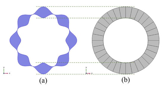
Figure 1.
Structure of the capacitor angle sensor: (a) petal-shaped rotor and (b) fan-shaped stator.
Figure 2 shows the structural schematic diagram; the electrode material is copper, the rest is air domain. As shown in Figure 2a, the petal-form sensitive electrodes are sine-wave shapes in polar coordinates, sorted by X number of cycles (in this design, X = 8). The corresponding cycle angle is 2π/X = 45°. The construction of the petal-form sensitive electrode is shown in Figure 1a with a blue area boundary. The red dotted ring (with radius R) is the centerline of the boundary; R1 and R2 represent the inner and outer contour lines, respectively. The green dotted lines are the centers of amplitude of the cosine functions R1 and R2, and τ is the amplitude. The θ is the mechanical angle and the X· θ is the electric angle, which means that the electric angle is X-times the mechanical angle. The mechanical angle θ is a variable of integration. In polar coordinates, the equations of the two boundary functions are expressed as follows:
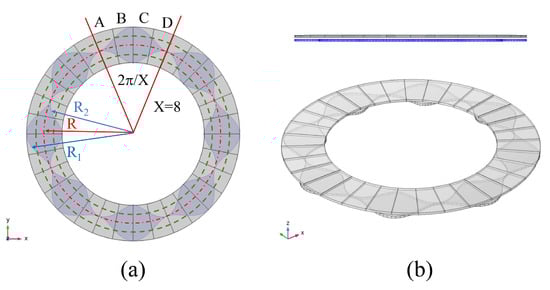
Figure 2.
(a) Mathematical model schematic and (b) side and stereo views.
In this design, R = 50 cm and τ = 5 cm; substituting R, τ and X into (1):
The solid red line area in Figure 2a indicates induction electrodes composed of four fan-shaped electrodes in one group, corresponding to a petal-form sensitive electrode; the four fan-shaped electrodes within a cycle, labelled A, B, C and D, are cycles in turn. Given the capacitance values of fan-shaped electrodes A, B, C and D, with corresponding petal-form electrode areas (CA, CB, CC and CD), the differences between A and C, and B and D (CA–CC and CB–CD) were used to obtain two sine and cosine signals with phase differences of 90 degrees, thus realizing the high-precision measurement of the angle [20]. According to the capacitive coupling principle, the capacitances between the sensitive electrode on the rotor and the four collection electrodes on the stator could be obtained and presented as:
Substituting (1) into (3):
In circuit processing, four capacitance-to-voltage (C–V) convertors and two differential amplifiers were used to eliminate the common element via CA–CC and CB–CD and presented as:
Equation (5) shows that CA–CC and CB–CD, the two sine and cosine signals, just depend on the angle θ. The capacitance of CA, CB, CC and CD could be simulated using COMSOL Multiphysics; subtracting according to the (5), the sine and cosine signals could be simulated, and the angle θ could be calculated. Figure 2b shows side and stereo views of the structure; the 1 mm air domain in the middle is visible.
3. Results and Discussions
Given the limited number of domains in the simulation, its one cycle structure was selected so that the capacitance of CA, CB, CC and CD would be less than X times the actual measured capacitance. The parameter selection for the article, the air domain interval and the number of cycles (X) were determined by the minimum capacitance in the design. Figure 3a shows the relationship between the minimum capacitance and the air domain interval distance. The capacitance values of the parallel capacitor plates were made inversely proportional to the distance so that if the distance is more than 2 mm, the capacitance change due to rotation is difficult to obtain at the minimum capacitance position. Additionally, if the distance was too small, collisions would likely occur in the actual installation, so 1 mm spacing was chosen. Similar results are shown in Figure 3b, which portrays the relationship between the minimum capacitance and the number of cycles (X); a smaller X corresponds to less accuracy, but a higher X leads to a too small capacitance at the position of minimum capacitance. Therefore, X was chosen as equal to eight.
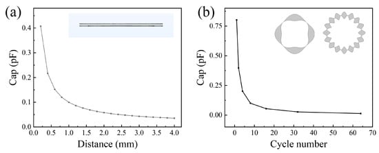
Figure 3.
The parameter selection: (a) the relationship between the minimum capacitance and the air domain interval distance and (b) the relationship between the minimum capacitance and the number of cycles X; 4 and 16 cycles are examples in the illustration.
In this study, the finite element method (FEM) was utilized to investigate the performance of the capacitive angle sensor by meshing the structure, as shown in Figure 4a. The petal-form sensitive electrode patterns were drawn using a GeoGebra graphing calculator, converted into DXF format files and then imported to COMSOL Multiphysics; the fan-shaped electrodes were built in COMSOL Multiphysics and used its Boolean operations. All electrode material was made of copper, and a sphere with a zero charge boundary condition applied to its outer surface truncated the air space surrounding the device. A DC voltage was applied to the petal-form sensitive electrode to determine the capacitance. Under the assumption of electrostatic conditions, the surface of each electrode was at the same potential. The air domain of the model was assumed the ideal insulator.
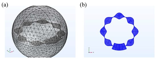
Figure 4.
(a) Overall model with mesh generation and (b) middle section of Figure 4a with one cycle of fan-shaped electrodes.
In order to facilitate data statistics and collation, there were four fan-shaped electrodes in one cycle to simulate the capacitance value. Although an error was found during the simulation, the structure was improved. In COMSOL, sector electrodes can be separated from each other by dividing the domain, whereas during the simulation process, it was found that the result had an error if the split domains were close together. This is shown in the red box in Figure 5a (enlarged in Figure 5b). Therefore, an interval was designed at the boundary to reduce the error in the simulation, as shown in Figure 5c.
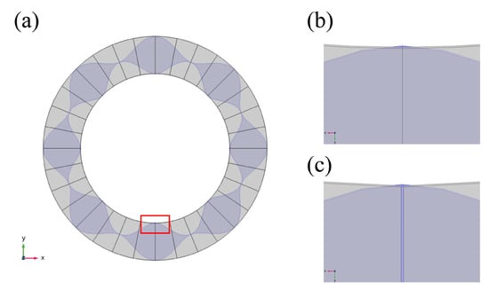
Figure 5.
(a) Domain of division; (b) enlarged section corresponding to the red box in (a); and (c) improvements made to (b).
A schematic diagram of the error is shown in Figure 6. Figure 6a shows the size of the interval angle between the two fan-shaped electrodes and the initial capacitance differences between A and D, and B and C. According to the previous principle, at the initial moment, the capacitance values of CA and CD, and CB and CC should have been the same because they were same area. The capacitance differences in CA–CD and CB–CC should have been zero. However, when the interval angle was zero, the capacitance difference was approximately 0.03 pF. According to the designed parameters, the capacitance value of a single sector electrode plate ranged from 0.15–1.8 pF; this error would affect the calculation of the angle. Figure 6b shows the final CA–CC and CB–CD; the two functions were sine and cosine functions with a phase difference of 90 degrees during a complete circle rotation, and there were eight signal cycles within 360°. However, due to the existence of an initial error, the two functions always had different values. Figure 6c shows a single cycle of 45° data; the difference can clearly be seen. The calculation angle of data in Figure 6c was compared with the theoretical angle; as shown in Figure 6d, there were some nonlinearities. Subtracting each, it was found that the error represented a sinusoidal signal, with a difference ranging from 0.7 to −0.4 degrees, as shown in the illustration of Figure 6d. The main source of the nonlinearities was the initial capacitance difference, which was primarily caused by fan-shaped electrodes segments without gaps left on the side between the electrodes; this could cause some calculation errors.
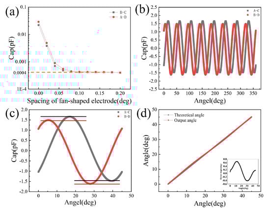
Figure 6.
COMSOL simulation data results: (a) the initial capacitance difference; (b) curves of CA–CC and CB–CD; (c) a single cycle of 2π/X (45°) from Figure 6b and the difference; and (d) the calculation angle and the theoretical angle, the error in the illustration.
In order to solve the problem, a certain angle was added between the fan-shaped electrodes. However, the increase in spacing would have occupied the electrode area and reduced the effective measurement area. As shown in Figure 6a, when the spacing reached 0.08°, the error began to approach the constant of 0.0004 pF; therefore, the spacing angle was set at 0.1°. After adjusting the curvature factor, the initial capacitance difference was further reduced to 0.001 pF, which was equivalent to the capacitance difference obtained by rotating 0.005°, so that the final error could be ignored. The model was simulated again; the result is shown in Figure 7.
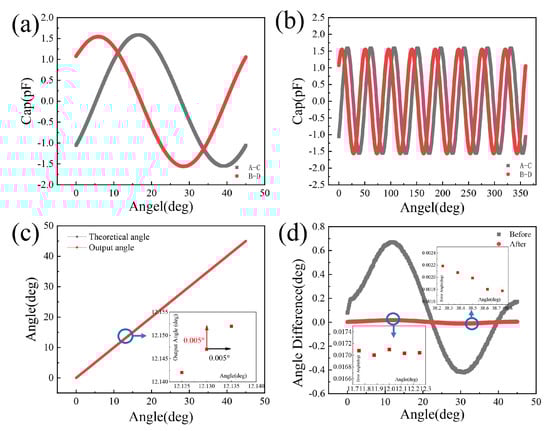
Figure 7.
The improved COMSOL simulation results: (a) a single cycle of 2π/X (45°); (b) curves of CA–CC and CB–CD; (c) improved calculation angle and theoretical angle; and (d) the error comparison.
Figure 7a and Figure 7b show CA–CC and CB–CD, respectively, within the range of 45° in a single cycle and within the range of 360° in a full cycle after adjustment. In comparison with Figure 6, it can be seen that the error between calculation angle and theoretical angle was eliminated after adjustment. When comparing Figure 6c and Figure 6b, it can be seen that after adjustment, the original phase difference was maintained, whereas the error was eliminated. Figure 7c was obtained by calculating the angle of data in Figure 7a. The difference was much smaller, and the angle obtained was consistent with the theoretical value. The minimum rotational step size can be 0.005°. When comparing the error values before and after adjustment, it was noted that the error after adjustment was significantly reduced. And the error angle after adjustment, which is obtained by subtracting the theoretical angle from the calculation angle, was within 0.0175°, and the minimum angle difference value was 0.0018°, as shown in Figure 7d. The mechanism of a capacitive angle sensor was simulated using COMSOL Multiphysics.
4. Conclusions
The theoretical analysis and structure construction were designed and described based on the petal-form electrode structure of a capacitive angle sensor; next, the simulation was realized using COMSOL Multiphysics. Errors were found in the earlier simulation results, which affected the accuracy of angle calculations. The reason for the simulation errors was analyzed and reduced via structural improvement. A 0.1° angle was added between each fan-shaped electrode, and the simulation was carried out again; this effectively solved the errors in the initial capacitive value, and the obtained data graph was close to the theory. The calculated angle error was greatly reduced and was consistent with the theoretical angle. It is hoped that using a COMSOL Multiphysics simulation of the designed capacitive angle sensor will inspire new ideas in capacitive angle sensor research.
Author Contributions
J.W. wrote the main manuscript text; Z.M. and J.W. conceived the experiments; Z.M. and X.Z. conducted the experiments; W.M. provided resources (the COMSOL Multiphysics copyright number). Y.Y. was writing-review. All authors analyzed the results and reviewed the manuscript. All authors have read and agreed to the published version of the manuscript.
Funding
This research is supported in part by the CAS (Chinese Academy of Sciences) Leading Science and Technology (category A) Project (XDA22020102).
Institutional Review Board Statement
Not applicable.
Informed Consent Statement
Not applicable.
Data Availability Statement
Not applicable.
Conflicts of Interest
M.W. provided the COMSOL Multiphysics copyright number. The other authors declare no conflict of interest.
References
- Kwon, Y.; Kim, W. Development of a New High-Resolution Angle-Sensing Mechanism Using an RGB Sensor. IEEE/ASME Trans. Mechatron. 2014, 19, 1707–1715. [Google Scholar]
- Agarwal, R.; Bhatti, G.; Singh, R.R.; Indragandhi, V.; Suresh, V.; Jasinska, L.; Leonowicz, Z. Intelligent Fault Detection in Hall-Effect Rotary Encoders for Industry 4.0 Applications. Electronics 2022, 11, 3633. [Google Scholar] [CrossRef]
- Algburi, R.N.; Guo, H.L. Detecting feeble position oscillations from rotary encoder signal in an industrial robot via singular spectrum analysis. IET Sci. Meas. Technol. 2020, 14, 600–609. [Google Scholar] [CrossRef]
- Wang, H.; Wang, J.; Chen, B.; Xiao, P.; Chen, X.; Cai, N.; Ling, B.W.K. Absolute Optical Imaging Position Encoder. Measurement 2015, 67, 42–50. [Google Scholar] [CrossRef]
- Park, J.W.; Nguyen, H.X.; Tran, T.N.C.; Jeon, J.W. A Linear Compensation Method for Improving the Accuracy of an Absolute Multipolar Magnetic Encoder. IEEE Access 2021, 9, 19127–19138. [Google Scholar] [CrossRef]
- Fernandes, J.F.T.; Lamb, K.L.; Clark, C.C.T.; Moran, J.; Drury, B.; Garcia-Ramos, A.; Twist, C. Comparison of the FitroDyne and GymAware Rotary Encoders for Quantifying Peak and Mean Velocity During Traditional Multijointed Exercises. J. Strength Cond. Res. 2021, 35, 1760–1765. [Google Scholar] [CrossRef]
- Wang, W.; Wu, L.; Shi, Z.Y.; Peng, D.L.; Yang, J.S. A Self-Compensation Algorithm for Electromagnetic Rotary Encoder With Unbalanced Installation. IEEE Sens. J. 2019, 19, 5514–5520. [Google Scholar] [CrossRef]
- Wang, H.W.; Peng, K.; Liu, X.K.; Yu, Z.C.; Chen, Z.R. Design and Realization of a Compact High-Precision Capacitive Absolute Angular Position Sensor Based on Time Grating. IEEE Trans. Ind. Electron. 2021, 68, 3548–3557. [Google Scholar] [CrossRef]
- Cai, N.; Xie, W.; Peng, H.X.; Wang, H.; Yang, Z.J.; Chen, X. A Novel Error Compensation Method for an Absolute Optical Encoder Based on Empirical Mode Decomposition. Mech. Syst. Signal Process. 2017, 88, 81–88. [Google Scholar] [CrossRef]
- Kim, Y.K.; Kim, K.S.; Kim, S. A Portable and Remote 6-DOF Pose Sensor System with a Long Measurement Range Based on 1-D Laser Sensors. IEEE Trans. Ind. Electron. 2015, 62, 5722–5729. [Google Scholar] [CrossRef]
- Miljkovic, G.S.; Denic, D.B. Redundant and Flexible Pseudorandom Optical Rotary Encoder. Elektron. Ir. Elektrotechnika 2021, 26, 10–16. [Google Scholar] [CrossRef]
- Wang, Y.; Zhu, Z.; Zuo, Z. A Novel Design Method for Resolver-to-Digital Conversion. IEEE Trans. Ind. Electron. 2015, 62, 3724–3731. [Google Scholar] [CrossRef]
- Pavlov, P.A.; Filatov, Y.V.; Zhuravleva, I.B. Calibration of rotary encoders with different interfaces by means of a dynamic goniometer. Opt. Eng. 2021, 60, 074105. [Google Scholar] [CrossRef]
- Tameh, T.A.; Sawan, M.; Kashyap, R. Smart Integrated Optical Rotation Sensor Incorporating a Fly-by-Wire Control System. IEEE Trans. Ind. Electron. 2018, 65, 6505–6514. [Google Scholar] [CrossRef]
- Das, S.; Sarkar, T.S.; Chakraborty, B. Simple approach to design a capacitive rotary encoder. IET Sci. Meas. Technol. 2018, 12, 500–506. [Google Scholar] [CrossRef]
- Kumar, A.S.A.; George, B.; Mukhopadhyay, S.C. Technologies and Applications of Angle Sensors: A Review. IEEE Sens. J. 2021, 21, 7195–7206. [Google Scholar] [CrossRef]
- Ferrari, V.; Ghisla, A.; Marioli, D.; Taroni, A. Capacitive Angular-Position Sensor with Electrically Floating Conductive Rotor and Measurement Redundancy. IEEE Trans. Instrum. Meas. 2006, 55, 514–520. [Google Scholar] [CrossRef]
- Zheng, D.Z.; Zhang, S.B.; Wang, S.; Hu, C.; Zhao, X.M. A capacitive rotary encoder based on quadrature modulation and demodulation. IEEE Trans. Instrum. Meas. 2015, 64, 143–153. [Google Scholar] [CrossRef]
- Li, X.J.; Meijer, G.C.M.; DeJong, G.W.; Spronck, J.W. An accurate low-cost capacitive absolute angular-position sensor with a full-circle range. IEEE Trans. Instrum. Meas. 1996, 45, 516–520. [Google Scholar]
- Hou, B.; Li, C.; Gao, Z.Y.; Wei, Q.; Zhou, B.; Zhang, R. Design, Optimization, and Compensation of a High-Precision Single-Excitation Absolute Capacitance Angular Encoder up to +/−4. IEEE Trans. Ind. Electron. 2019, 66, 8161–8171. [Google Scholar] [CrossRef]
- Bucolo, M.; Buscarino, A.; Famoso, C.; Fortuna, L.; Gagliano, S. Imperfections in Integrated Devices Allow the Emergence of Unexpected Strange Attractors in Electronic Circuits. IEEE Access 2021, 9, 29573–29583. [Google Scholar] [CrossRef]
- Labibi, M.; Mehran, M. Novel liquid-based linear capacitive inclination micro-sensor with totally 360 degrees dynamic range. IET Circuits Devices Syst. 2019, 13, 630–636. [Google Scholar] [CrossRef]
- Rajabi-Nezhad, A.; Razi-Kazemi, A.A.; Soheyli, M.; Malekipour, F. Assessment of Different Compact Marx Generator Structures on the Voltage Profile. IEEE Trans. Plasma Sci. 2020, 48, 189–195. [Google Scholar] [CrossRef]
Disclaimer/Publisher’s Note: The statements, opinions and data contained in all publications are solely those of the individual author(s) and contributor(s) and not of MDPI and/or the editor(s). MDPI and/or the editor(s) disclaim responsibility for any injury to people or property resulting from any ideas, methods, instructions or products referred to in the content. |
© 2023 by the authors. Licensee MDPI, Basel, Switzerland. This article is an open access article distributed under the terms and conditions of the Creative Commons Attribution (CC BY) license (https://creativecommons.org/licenses/by/4.0/).