1. Introduction
The Department of Vehicle System Dynamics at the German Aerospace Center (DLR) is researching novel control algorithms for vehicles. Among others, the ROboMObil (ROMO) [
1], a robotic and over-actuated electric vehicle, which can control the steering angles and in-wheel torques by means of four-wheel robots independently, is available for testing. Prototypical vehicles such as the ROMO are fundamentally different from ordinary production vehicles in terms of their basic architecture and driving characteristics. Although novel control methods can be well represented by the ROMO’s four separate wheel-robots, investigations can only be transferred to road vehicles to a limited extent. Furthermore, such concept vehicles usually do not have road approval, so that the developed functions cannot be tested in challenging road traffic scenarios, but only on secured test sites. To address these issues, the AI-For-Mobility (AFM) project was started at the DLR Institute of System Dynamics and Control (SR).
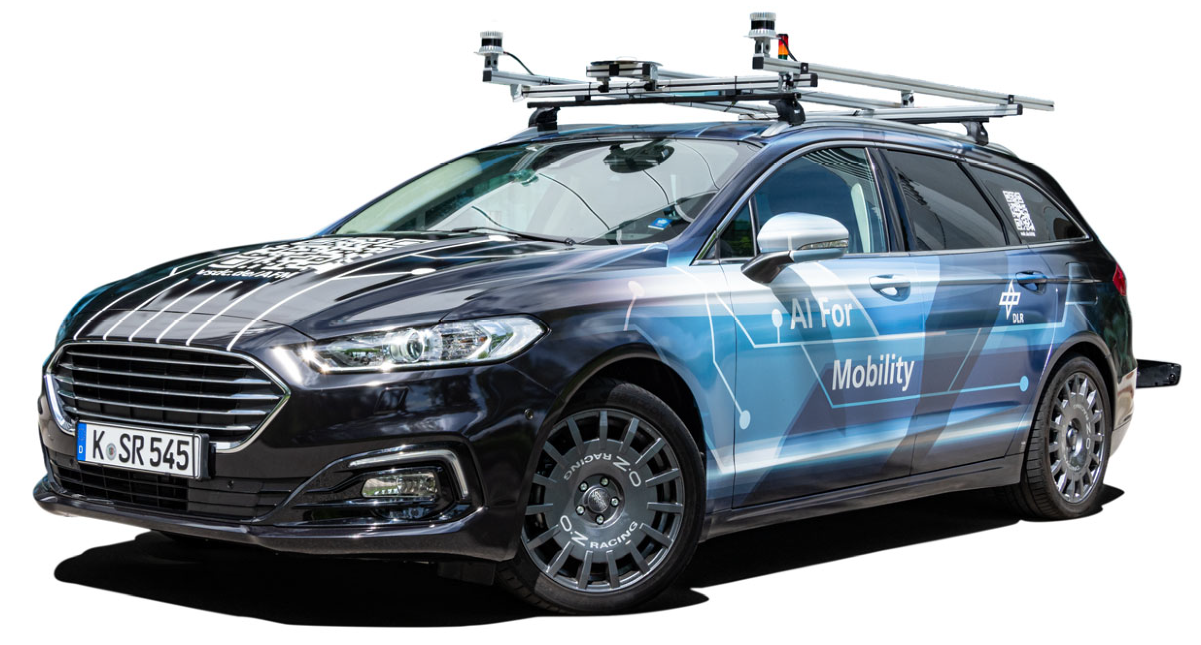
The AFM, illustrated in
Figure 1, has a special road approval for certain operation modes, and thus covers a larger range of possible use cases in experiments also on the public road network. The intention of the AFM project was to modify and equip a production vehicle to use it as a test platform for novel AI-based control system functions [
2].
On the internet blog of the Department of Vehicle System Dynamics [
2], news about the research activities and the AFM project are continuously published. The explanations in this paper are partly based on the contributions indicated there.
1.1. The AI-For-Mobility Concept
Within the AI-For-Mobility project, a production hybrid car was chosen as a basic platform because of its full by-wire vehicle architecture. In order to enable automated operation, a drive-by-wire (DBW) kit was designed for the vehicle. It allows to drive defined and reproducible maneuvers, and thus to systematically analyze the implemented AI-based control algorithms. Since AI-based methods are data-driven, the vehicle is equipped with a variety of sensors to measure the states and internal values, as well as environmental quantities as, e.g., the road condition and the surrounding scenery. The vehicle sensors are synchronously logged on a rapid control prototyping system [
3].
The development of algorithms for vehicle dynamics functions is a broad field. A classification can be made using the pyramidal control architecture presented in
Figure 2. It comprises three layers related to the corresponding fields of application as follows.
The top layer deals with the vehicle application and is used to generate trajectories or paths. Motion planning is performed on the basis of environmental information. For this purpose, the AFM is equipped with various perception sensors such as cameras, lidar or radar sensors. By means of advanced machine learning methods, the driving environment is recorded and processed in real-time. The resulting motion requirements for the three planar degrees of freedom are passed to the Motion Execution layer.
This layer contains the vehicle dynamics control, which calculates appropriate vehicle dynamics quantities to realize a required motion and ensures the safe operation of the vehicle. The AFM’s extensive sensor equipment enables development and testing of advanced AI control approaches. The horizontal vehicle motion of the AFM described by the longitudinal (throttle and brake) and lateral (steering) dynamics is controlled by a full by-wire kit. In order to control the vehicle’s vertical dynamics, the AFM is in turn equipped with semi-active dampers. The resulting actuator demands are then considered by the architecture layer lying below.
The lowest layer deals, for instance, with the actuator control of the steering and braking system. In the AFM, extensive information about the actuators is available for many sub-systems (e.g., by reading the vehicle CAN buses). Due to this feature, the AFM provides a suitable test platform for applications in this layer.
Note that some applications, such as state estimation methods, may span over multiple layers.
The AFM concept has been designed as a universal test platform for vehicle dynamics control approaches, which allows all applications of the layer model shown in
Figure 2 to be addressed consistently. The holistic capability for testing novel AI-based control methods makes the AFM a unique test platform. Most other vehicle demonstrators do not take all three layers into account, leading to a research gap in the context of vehicle dynamics. Some of these vehicle concepts are discussed in the following section.
1.2. Related Work
The autonomous vehicle Stanley [
5] was developed by a research team from the Stanford University for the DARPA Grand Challenge. The vehicle platform is based on a Volkswagen Touareg R5 and includes a drive-by-wire system. As part of the perception layer, Stanley is equipped with several different sensors, including laser rangefinders, radars, and cameras to perceive its environment. The control layer enables steering, acceleration, and deceleration of the vehicle in order to follow a trajectory generated by a path planner. The steering controller is based on a nonlinear feedback function with the cross-track error as function input. The longitudinal motion is determined by a PI error metric which either applies the brakes or the throttle. Besides lateral and longitudinal guidance, the vehicle does not enable controlling actuators for other applications, such as a semi-active suspension.
The company Five.ai [
6] developed an autonomous vehicle based on a Ford Fusion platform. The vehicle includes a drive-by-wire system and is equipped with a rich set of perception sensors, including lidars, radars and cameras. Besides motion planning [
7], Five.ai’s main research topics are image classification [
8], object tracking [
9,
10] and segmentation [
11,
12]. However, to the best of our knowledge, their research does not focus on the development of complex control algorithms for vehicle dynamics.
The Virtual Vehicle Research Center [
13] developed an Automated Drive Demonstrator which is based on a Ford Mondeo vehicle platform including a drive-by-wire kit. Their research topics, among many others, include real-time sensor fusion, validation and test of automated driving functions, novel human-machine interface concepts for increased passenger comfort and fail-operational active safety.
In ref. [
14], an autonomous vehicle based on a KIA Soul platform was presented with a minimal sensor suite. For perception tasks, two cameras, a radar and a lidar sensor were integrated into the vehicle and neural networks were trained for object detection tasks. For longitudinal control, a PID feedback controller is applied in order to minimize the error between the current values of the motion in the longitudinal direction and the target values. For lateral control, an approach based on classical Model-Predictive Control (MPC) is utilized.
In contrast to the autonomous vehicle concepts introduced above, the main conceptualization of the AFM is based on enabling the development of a variety of AI-based control algorithms for different tasks throughout the entire vehicle. Further, it allows addressing all three application layers introduced in
Figure 2. In addition to a rich sensor set, the AFM includes powerful computing platforms that enable testing and validating complex AI-based control methods for a wide range of applications, which is not only limited to longitudinal and lateral control, such as semi-active suspension or state estimation approaches.
1.3. Contribution and Overview of This Work
The contribution of this work is as follows:
The universal test platform AFM and its setup is presented in detail, focusing on enabling research on AI-based vehicle dynamics control approaches for a wide variety of control tasks, including both horizontal and vertical dynamics control.
The setup and integration of a variety of different sensors on the AFM are shown. These sensors holistically measure all vehicle states including extensive quantities about the vehicle itself, as well as its environment, where over 400 signals are recorded.
The setup of state-of-the-art high performance in-vehicle computing platforms is demonstrated, which enable real-time processing and managing of all information between the sensors, actuators and control algorithms as a crucial requirement for real-time automated driving.
The AFM’s high-fidelity multi-domain and multi-body-system vehicle models are introduced, which enable the virtual controller design and early risk assessments before test drives on the real-world vehicle.
The remainder of this work is organized as follows. In
Section 2, the vehicle architecture is introduced, where the suspension design, the fully by-wire control system and the in-vehicle computing platforms are presented. In
Section 3, the extensive sensor set of the AFM is introduced, including the horizontal and vertical dynamics sensors, as well as the environment perception sensors. Further, in
Section 4, the AFM’s high-fidelity vehicle model is outlined, which was developed in Modelica. Lastly, in
Section 5, an overview of research activities on the AFM is presented. This work is concluded in
Section 6 and an outlook is provided.
2. Vehicle Architecture
Inspired by the pyramid structure shown in
Figure 2, this section introduces the design of the AFM vehicle architecture.
Section 2.1 presents the AFM’s suspension design forming a part of the “Actuator Control” layer. The drive-by-wire kit, which enables control of the planar vehicle motion and represents the “Motion Execution” layer, is outlined in
Section 2.2. Next, the in-vehicle computing platforms contained in the “Vehicle Application” layer are discussed. Sensor signal processing, recording and control algorithms are executed on these platforms.
Section 2.4 introduces the interface for operating the AFM during test drives. Finally, the electrical power supply system of the vehicle’s test equipment is described in
Section 2.5.
2.1. Suspension Design
In order to be able to demonstrate vertical dynamics control applications on the AFM, the vehicle is equipped with a semi-active suspension technology. First of all, it allows for addressing safety aspects since the road-holding can be influenced. In addition, it helps to eliminate undesirable effects regarding drive comfort (e.g., kinetosis) by minimizing vehicle body accelerations. Since automated driving functions become more widespread and passengers gain more time for other activities, the demands on driving comfort increase. Overall, semi-active dampers enable adaptation to varying road excitations, reaction to critical driving situations and optimization of both driving safety and comfort (cf. [
15]).
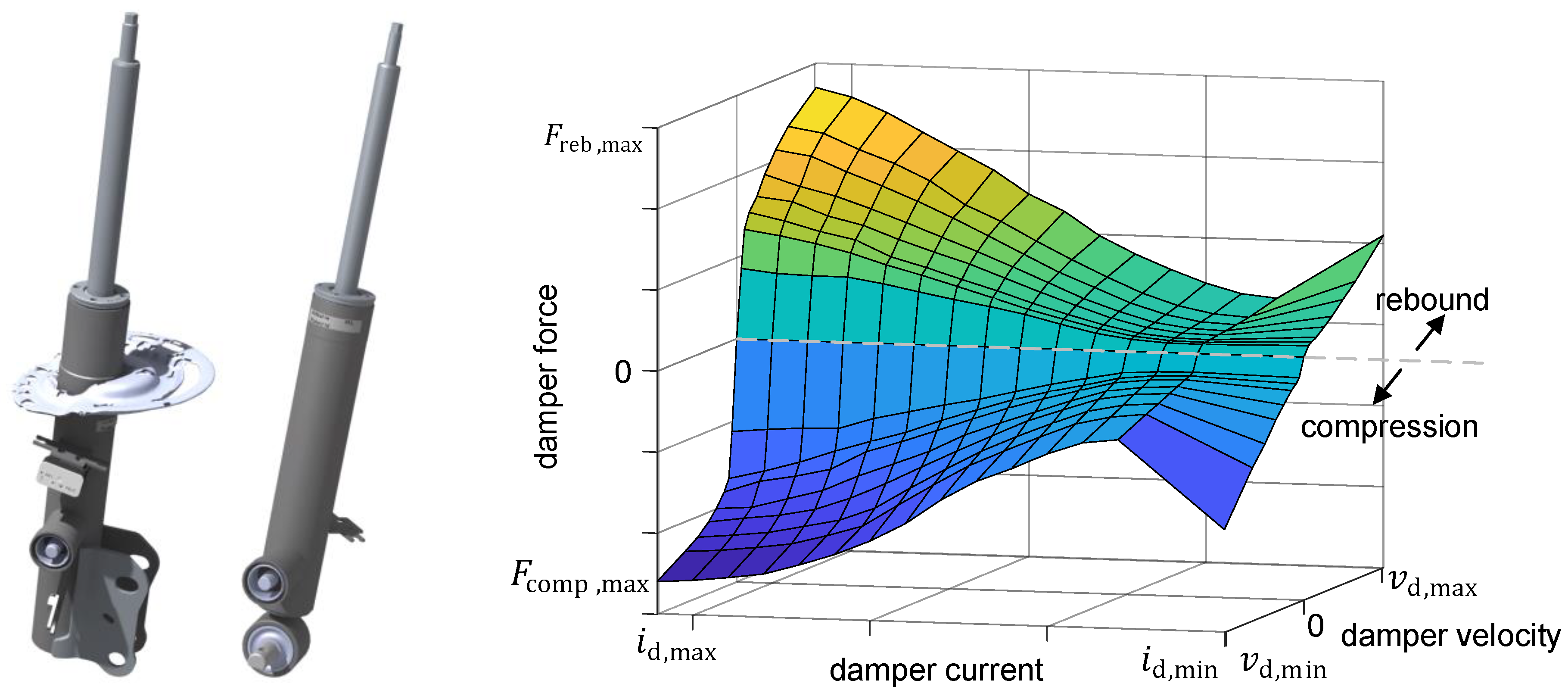
The goal of the suspension conversion was to maintain the same vehicle height as that of the basic vehicle in order to keep the AFM as closely as possible to comparable production vehicles. For this purpose, a damper (including its housing, piston rod, etc.) was completely redesigned and remanufactured (see left-hand side of
Figure 3).
The manufactured dampers were measured on a Roehrig damper test rig. As a result, a two-dimensional characteristic map linking the damper velocity
and the current
to the damper force
was identified (see right-hand side of
Figure 3).
The top mount bushing possesses a complex characteristic (6D damping, frequency dependence, etc.). In order to investigate the influence of the damper control on the vertical dynamics behavior, as well as to drive the AFM in a more precise and direct way, the standard top mount bushings were replaced by a uniball bearing.
The damper currents are controlled by an embedded controller unit (ECU). Vertical dynamics control algorithms can be computed in a stand-alone mode either on the ECU or on a Rapid Control Prototyping (RCP) platform. The latter then sends the current demand values to the dampers via the interconnected ECU [
16]. The modified suspension system was inspected by an independent technical testing authority resulting in the AFM’s approval for public road use even with controlled dampers.
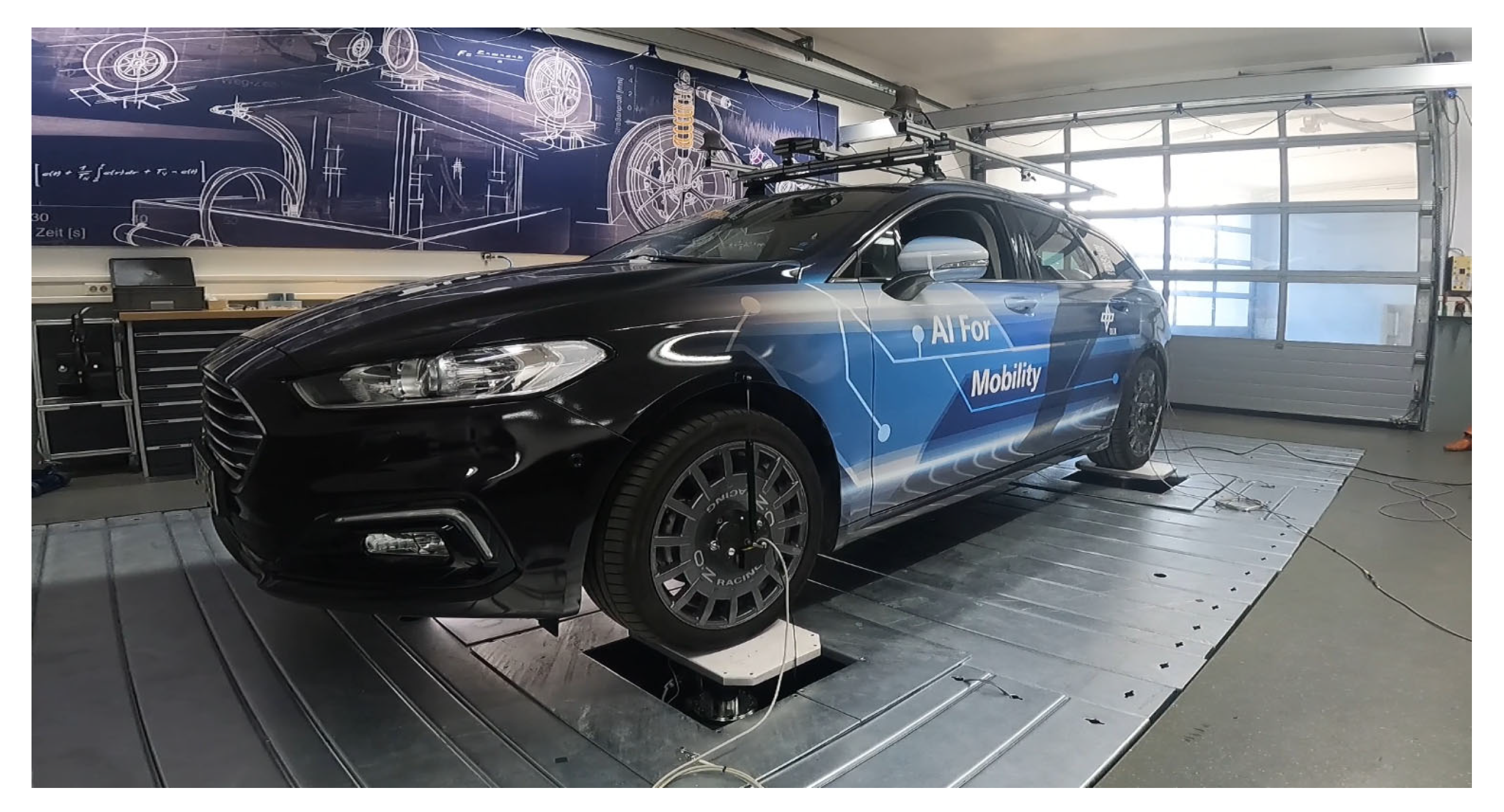
To investigate the vertical dynamics characteristic of the complete vehicle and to design and evaluate controllers, the AFM’s behavior was analyzed on a 4-post test rig (see
Figure 4).
During this process, the vehicle is placed on four hydraulically driven vertical posts, each following its predefined position signals. The posts induce a vertical movement of the vehicle. In this way, driving on precisely defined road profiles (such as, for instance, synthetic profiles according to ISO 8608 [
17]) can be simulated in a reproducible manner. Moreover, it is possible to install additional sensors under unvarying conditions of the test rig. Its sensor system allows the measurement of the post position, speed, accelerations and wheel loads. In addition to the test rig sensors, the AFM is equipped with its own vertical dynamics sensors as described in
Section 3.3. They enable recording of many important quantities. In several hundred separate experiments with different excitations, more than 50 measured variables were recorded in each case. The measurement data were used, among others, to identify and validate the vertical dynamics part of the AFM’s high-fidelity vehicle model (cf.
Section 4).
2.2. Full By-Wire Control System
The AFM is equipped with a full drive by-wire (DBW) kit. It enables control of the steering wheel angle or steering wheel torque (control of lateral dynamics), as well as of the throttle and brake pedal position (control of longitudinal dynamics). Furthermore, it is possible to actively select a gear via an extra actuator (shift by-wire) thanks to a modification of the gear selector. Besides the shift by-wire module, the DBW kit only uses the existing actuators of the basic vehicle. A virtual accelerator and brake pedal position is given via an emulator. The existing interface of the adaptive cruise control (ACC) function is utilized for controlling necessary braking and engine operations. To specify a steering wheel angle or steering torque, the interface to the electronic power steering (EPS) system is controlled by an ECU.
The DBW kit allows for driving reproducible maneuvers. This feature plays a key role for the evaluation of different control algorithms or setups since they can only be meaningfully compared on the basis of identical maneuvers. In addition, the DBW kit replaces the functionalities of a steering robot such that maneuvers like a Sine with Dwell test [
18] can be precisely performed.
The DBW system installed in the AFM provides several advantages compared to other systems where additional actuators have to be installed on the steering column and on the pedals of the basic vehicle in order to set a desired value mechanically. First, it reduces the costs of retrofitting additional actuators. Second, the DBW kit prevents different actuators from interfering with each other (e.g., in the case of an ESC intervention), which can lead to undesirable or even dangerous system behavior.
The DBW kit enables automated driving of the AFM over the entire operating range, from executing parking maneuvers with forward and reverse switching to high-speed driving. Automated driving is performed exclusively with an operator on board. As a safeguard, the activated DBW kit constantly monitors possible driver inputs. A detected steering wheel torque, brake or accelerator pedal position is interpreted by the system as a take-over request causing it to deactivate and return control to the human driver. As an additional safety mechanism, the driver can activate the emergency stop switch in the center console in case of an emergency, which disconnects the power supply to all auxiliary components and consequently the DBW kit (cf.
Section 2.5).
The AFM with its DBW kit was inspected by an independent technical testing authority. As a result, it received a special approval for public road use based on the review of circuit diagrams and safety mechanisms integrated by the system’s manufacturing company. The AFM is allowed to be operated on public roads when the system is enabled without any active intervention in the vehicle control. In this case, the subsystems of the DBW kit only collect data. As soon as the DBW system has been activated to influence the vehicle guidance, the AFM is allowed to be used only in test areas.
The DBW kit is connected via a CAN bus to the Rapid Control Prototyping (RCP) platform, on which all control algorithms are computed (see
Section 2.3.1) and from where the command values are sent to the DBW system.
2.3. In-Vehicle Computing Platforms
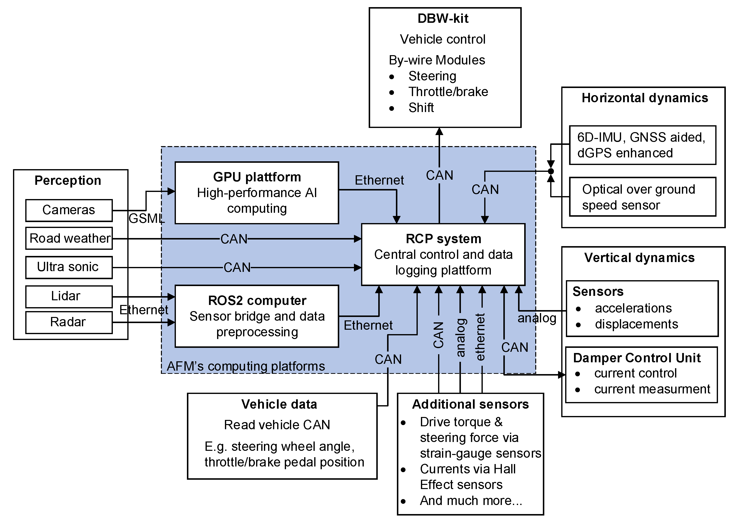
This section introduces the computing platforms installed in the vehicle. They process and manage all information between the sensors and actuators via intelligent data processing and control algorithms. The section starts with the description of the Rapid Control Prototyping (RCP) platform. It is the central data logging unit and runs all vehicle control and operation algorithms.
Section 2.3.2 deals with a high-performance multi-GPU-accelerated AI computing platform allowing the implementation of computationally intensive perception processing functions. Together with a Robot Operating System 2 (ROS2) computer presented in
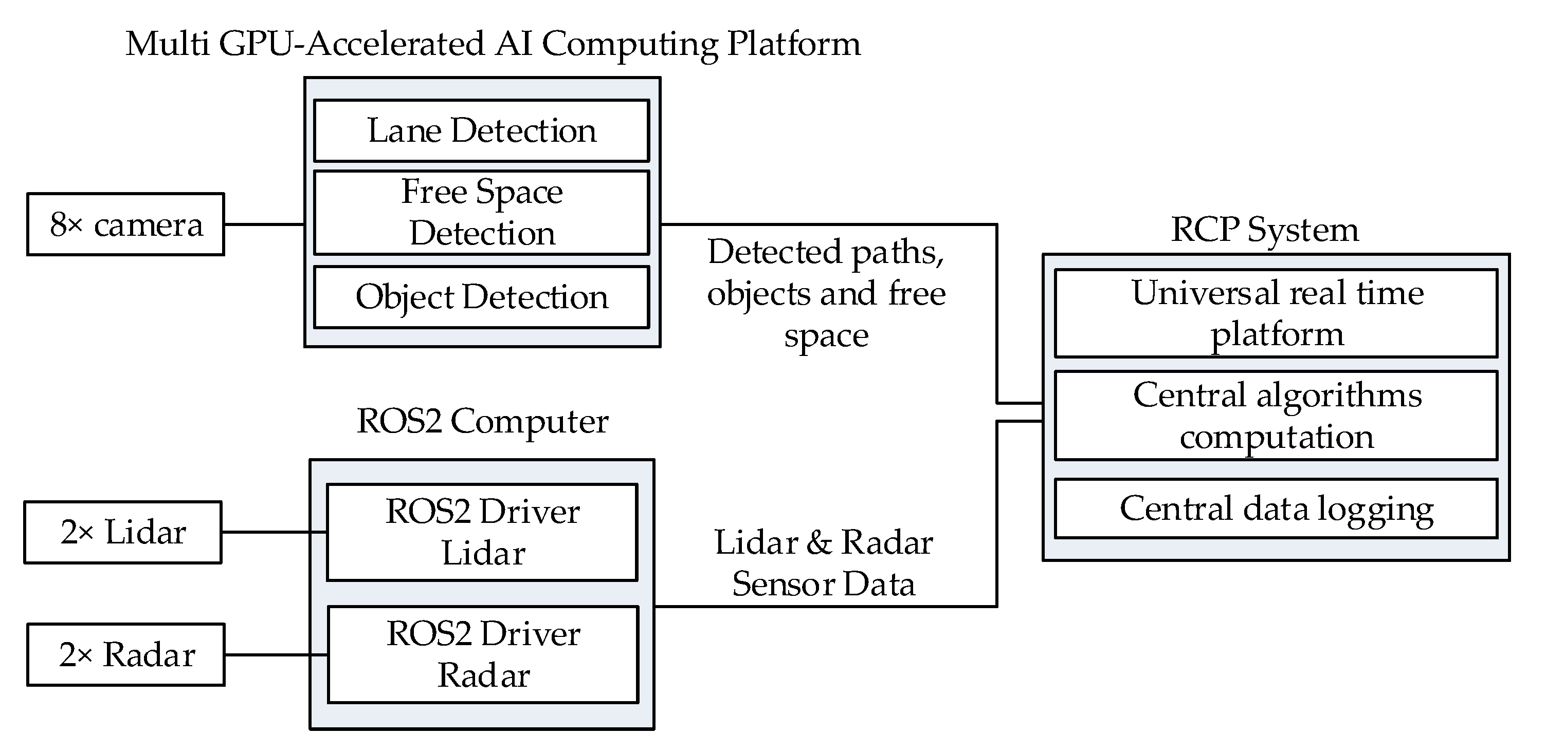
Section 2.3.3, the GPU computing platform forms a sensor bridge to the RCP platform. The overview of the connection of the aforementioned systems and the connected sensors is shown in
Figure 5.
In general, all algorithms running on the computing platforms in the AFM are executed in real time. When designing control algorithms, the real-time requirement must be taken into account. In the case of iterative procedures, this can be guaranteed by terminating the procedure after a time limit has been reached (the solution obtained in that case is only sub-optimal).
Note: The training of neural networks does not take place on the in-vehicle computing platforms, but instead on external powerful computers or computing clusters. The trained artificial neural networks are then executed on the systems in the AFM.
2.3.1. High Performance Rapid Control Prototyping (RCP) System
The RCP system is a powerful platform optimized for in-vehicle use. Integrated shock and vibration dampers ensure a high operational range for real-world tests. The quad-core Intel® Core™ i7-6820EQ processor ensures real-time performance. The system provides numerous interfaces for information transfer as, for instance, several CAN and Ethernet connectors as well as a multi I/O board allowing generation and measurement of both analogue and digital signals. All algorithms used to control the vehicle (by means of the DBW kit, semi-active dampers, etc.) are executed on the RCP system. In addition, the central data logging with cloud connectivity is performed here.
2.3.2. Multi-GPU-Accelerated AI Computing Platform
The AFM is equipped with a commercial multi-GPU platform for high-performance AI computing [
19], which provides a powerful basis for camera-based perception through convolutional neural networks. Therefore, all eight vehicle cameras are connected to the GPU platform. Further, three pre-trained deep neural networks for different perception tasks from a commercially available software framework [
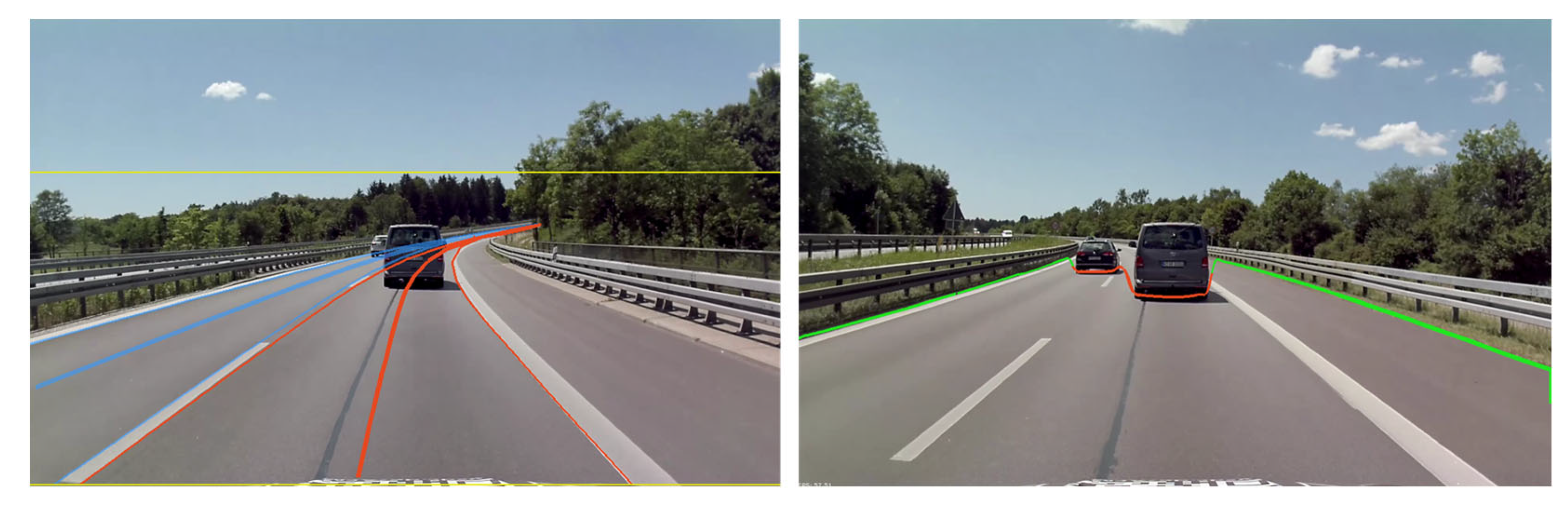
20] are applied, which enables the AFM to perceive the environment and to apply complex control algorithms for different driving scenarios and tasks. The first neural network is utilized for the real-time detection of the ego-vehicle’s ego-path, as well as the detection of the left and right adjacent lanes if they are present in the image (cf.
Figure 6, left).
The network returns the detected paths in the local camera coordinate system, which are afterwards transformed into the local vehicle coordinate system. Furthermore, the second neural network is used for the detection of the drivable free space in front of the vehicle, which is shown on the right side of
Figure 6. Again, the edge points of the detected free space in front of the vehicle are determined in the camera coordinate system and afterwards transformed into the vehicle coordinate system. Lastly, a neural network is applied for the detection of cars, pedestrians and traffic signs. The environmental information gathered through the neural network-based detection is forwarded to the RCP Control System, where the information is used within the AI-based control algorithms. Note that the commercially available neural networks are pre-trained and that different weather conditions might influence the detection performance.
2.3.3. ROS2 Computer and Sensor Bridge
In the AFM, a computer is integrated on which ROS2 is installed. This computer servers as a sensor bridge, where certain perception sensors, such as the lidar and radar sensors, are connected to the computer via ethernet. The computer enables the ROS2 drivers of the aforementioned sensors to run and to pre-process the incoming sensor data. Afterwards, the processed sensor information is forwarded via ethernet to the ROS2 interface of the RCP system, which serves as a central control unit. Here, the RCP system can control the overall vehicle while considering important environmental information obtained from the perception sensors connected to the ROS2 computer.
2.4. Vehicle Operation Interface
The AFM provides the same interfaces for driving as a production vehicle, namely accelerator and brake pedal, steering wheel, gear selector, etc. With the DBW kit deactivated, the AFM is able to be driven like a conventional production vehicle on public roads. When designing the interfaces of the AFM, one goal is to ensure that the driver can access all interfaces required to operate both the sensors and the hardware.
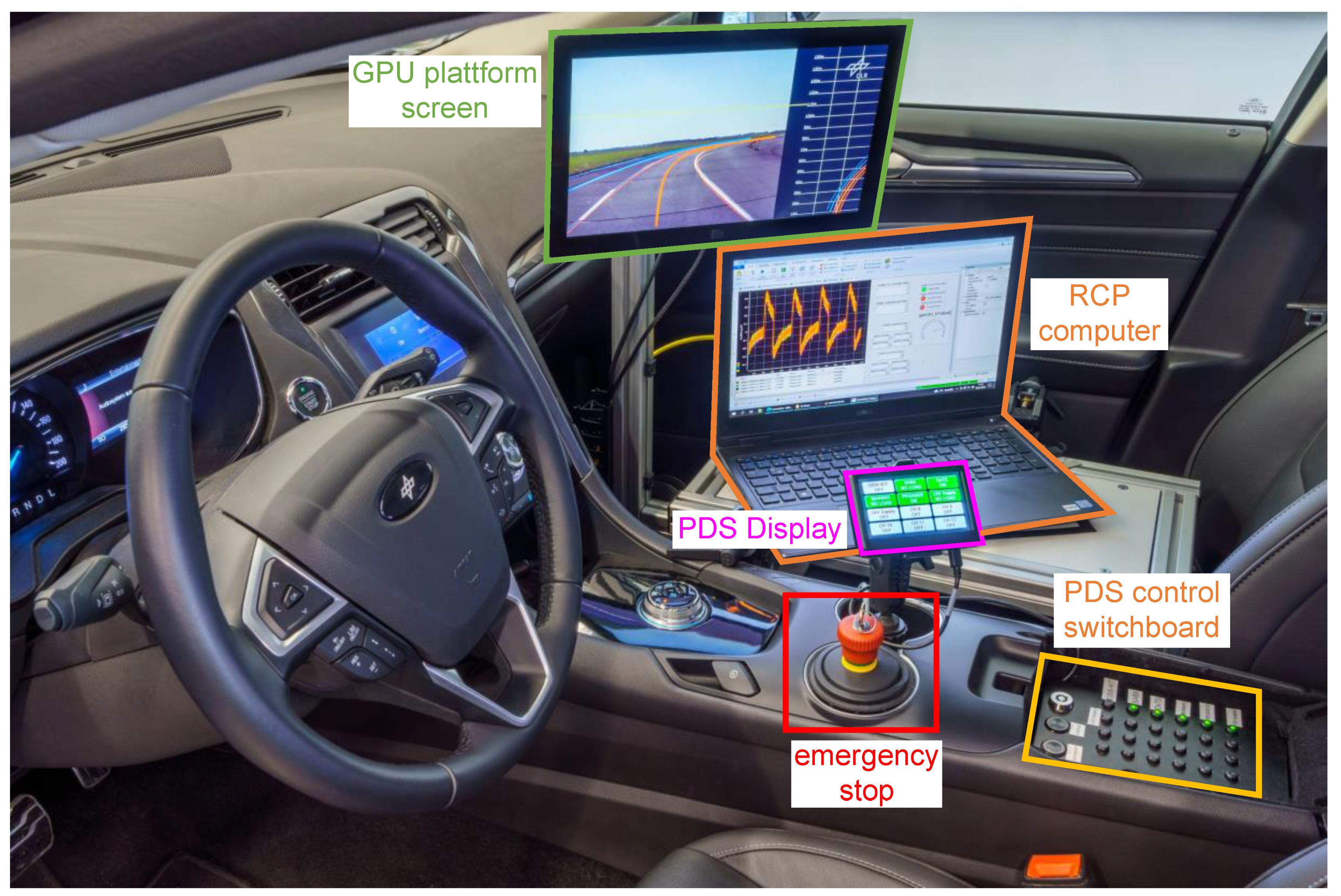
Figure 7 shows the front cabin of the AFM.
For turning sensors, actuators and other hardware components on and off, a control switchboard is provided in the center console. The panel is connected to the Power Distribution System (PDS) (cf.
Figure 8) and enables intelligent control of a total of 12 channels, each of which is connected to different consumers. In case of an emergency, the driver can disconnect them from the power supply via an emergency switch, which again makes the AFM technically equivalent to a production vehicle.
In the passenger seat, a rack was constructed on which further hardware can be mounted. This includes a notebook computer connected to the RCP platform, and thus representing the central interface to the vehicle development software. The computer is connected to the Internet via an LTE mobile modem and provides test engineers with remote access to the AFM. Hereby, it can be virtually monitored and controlled even if it is far away from the test field. In addition, the LTE modem also allows to upload the real-time data and to establish a connection to cloud-based applications. Another hardware component mounted on the rack is a screen connected to a high-performance GPU platform and other computers installed in the rear of the vehicle. The vehicle’s steering wheel buttons are readable via a vehicle CAN bus, and thus form an additional interface to the driver. For example, a certain button combination needs to be pressed to activate the DBW kit.
2.5. Electrical Power Supply Design
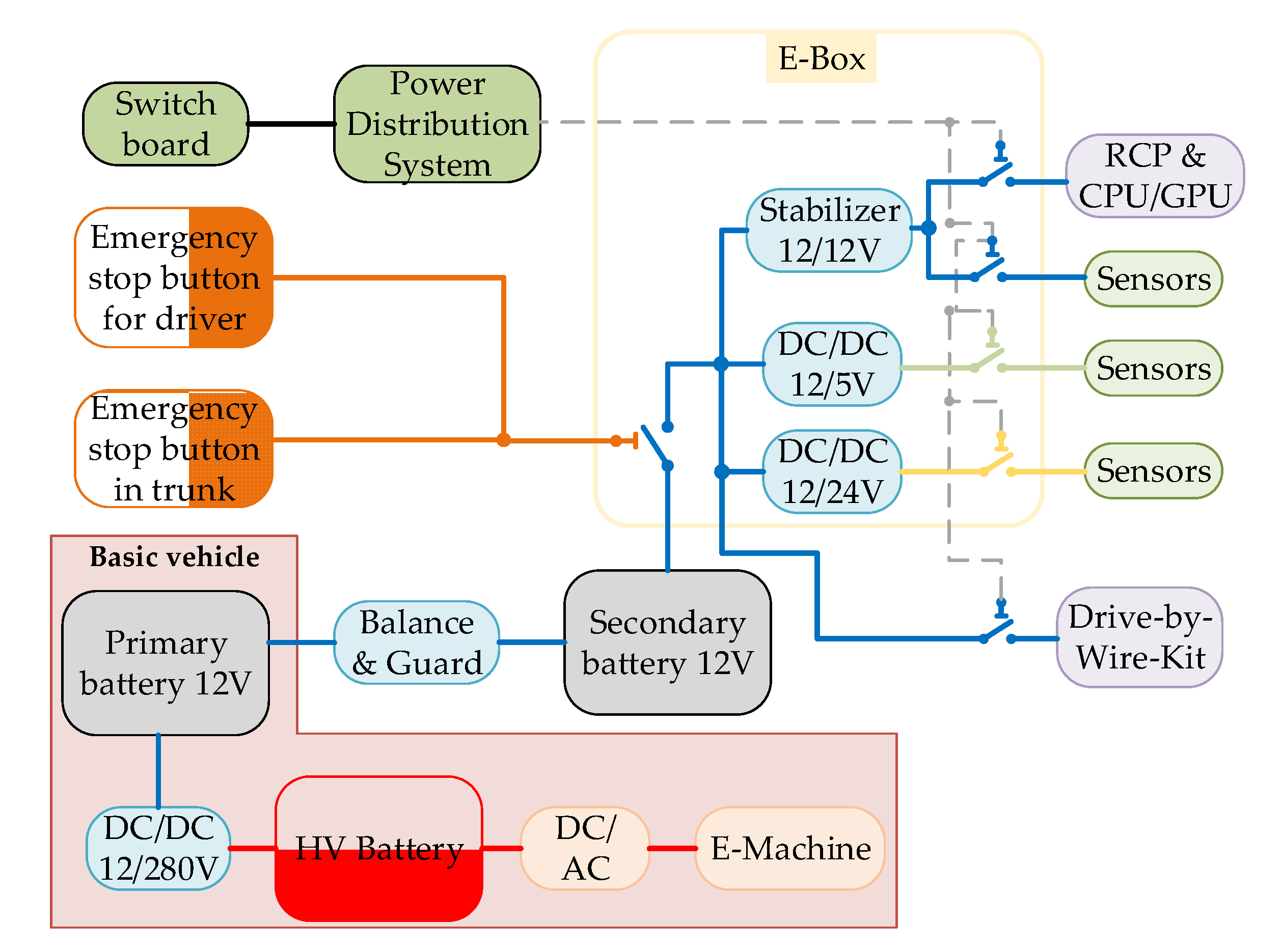
All additional electrical components of the AFM installed in the basic vehicle (sensors, actuators, DBW kit, etc.) must be supplied with power. For this purpose, the existing vehicle electrics are extended by an extra battery to ensure safe and robust operation of all additional consumers. The topology of the AFM’s electrical system is shown in
Figure 8.
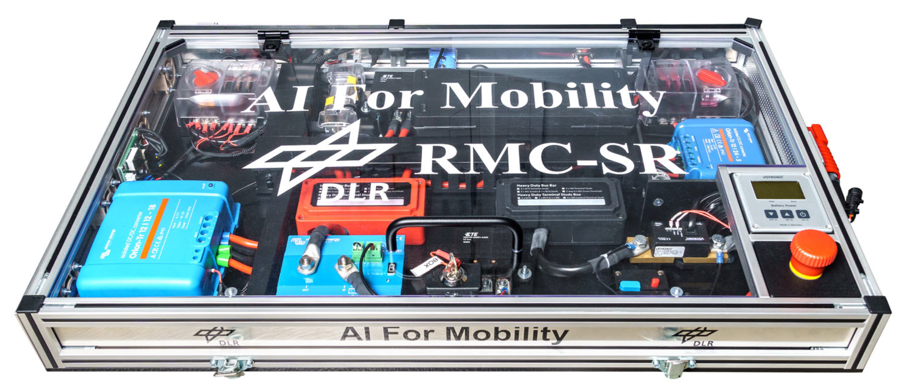
The AFM is a full hybrid electric vehicle (HEV), as can be seen in the lower part of the figure. In addition to the primary battery, a high-performance Absorbed Glass Mat (AGM) battery is integrated. The coupling is realized via an intelligent battery guard, which adaptively balances both batteries. Due to the safety aspects, it is possible to interrupt the power supply to all consumers via (emergency) off switches, making the AFM technically a passive series vehicle. Among the two emergency switches connected in parallel, one is located in the vehicle’s center console, so that the driver can intervene at any time. The second emergency stop switch can be found in the trunk of the vehicle where the control units for auxiliary electrics are located. All components of the vehicle’s auxiliary electrics are centrally placed in a modularly designed electrical box (E-box), see
Figure 9.
The temperature-controlled E-box contains DC/DC converters, which provide stabilized voltage levels of 5 V, 12 V and 24 V. Through a switchboard in the center console, the driver can comfortably and safely activate and/or deactivate various consumers by pressing a button. The interconnected power distribution system additionally monitors all connected consumers. Furthermore, preselected sensor or actuator setups can be defined, which can be manipulated by the driver.
Among all connected consumers, the RCP platform and the CPU/GPU system are by far the most power-intensive ones consuming more than 120 W and 300 W, respectively.
The currents of the installed auxiliary electrics are measured at certain key points by Hall effect sensors.
Note that the illustration of the AFM’s electrical topology in
Figure 8 contains no safety features such as fuses, switching relays, etc.
3. Sensor Architecture
Since data-driven methods require sufficient training data, adequate sensor equipment forms the backbone of the AFM. A variety of different sensors holistically measure all vehicle states, including extensive factors about the vehicle itself as well as its environment. Thus, a total of over 400 signals are recorded during test drives.
The section is structured as follows.
Section 3.1 outlines the network architecture showing the communication between the sensors, computing platforms, actuators and control units. This is followed by a more detailed presentation of the sensors, which can be basically divided into the following categories representing the corresponding
Section 3.2–
Section 3.5:
This section is partly based on contents of the Internet blog of the Department of Vehicle System Dynamics at DLR [
3].
3.1. Overview of the Sensor Equipment and Network Architecture
The real-time communication between different sensors, computing systems and actuators mainly takes place via CAN and ethernet buses or via A/D technology. An overview of the AFM’s network architecture is shown in
Figure 10.
The RCP platform is the central data-logging unit. In addition, all control algorithms and software required to operate the AFM in experimental mode are executed here. Further computing platforms installed in the vehicle are a multi-GPU-accelerated AI computing platform and a ROS computer used to (pre-) process the data from a large part of the perception sensors.
The measured data can be processed and logged on the RCP System synchronously. The lidar and radar sensors are connected to the ROS computer. Each sensor is operated individually with a ROS2 node, where the data is read and processed. After processing the sensor data, the information is forwarded to the RCP control system and used for several different control applications or logging. The ROS computer and the GPU computing platform operate as a bridge between the environmental sensors, whose data is (pre-) processed there, and the RCP platform, where the data is used in real time for vehicle control algorithms or is recorded.
3.2. Horizontal Dynamics
The horizontal dynamics describe all quantities of the vehicle’s planar motion and is dominant compared to the vehicle’s vertical dynamics. In addition to accelerations and velocities, this also includes the vehicle’s position (both translational and rotational). Acquisition of these quantities is essential for many vehicle control algorithms (see also control pyramid in
Figure 2, layers “Vehicle Application” and “Motion Execution”). Utilizing these quantities, advanced nonlinear state estimation algorithms such as [
21,
22] can be implemented on the AFM. The sensors of the AFM measure:
Accelerations, velocities and position of the vehicle’s center of gravity
A high-precision 6D Inertial Measurement Unit (IMU) installed close to the center of gravity captures all components of a vehicle motion. Two roof antennas additionally allow for fusing measurements by the global navigation satellite system (GNSS).
With the aim of improving the accuracy of the satellite measurements (GNSS), a mobile differential GPS (dGPS) base station provides correction data to the IMU/GNSS platform installed in the vehicle.
Longitudinal and lateral velocities along with complementary vehicle side-slip angle
An optical speed sensor scans the road surface to measure the vehicle’s over ground velocity. Based on these measurements, the vehicle’s side-slip angle is determined. Note that both longitudinal and lateral velocity can be measured precisely.
3.3. Vertical Dynamics
The vertical dynamics describe the movement of a vehicle in the vertical direction, usually induced by the ground unevenness and passed on to the vehicle chassis by the wheels and suspension. Apart from comfort considerations for passengers, vertical dynamics are strongly coupled with horizontal dynamics via the wheel load distribution and represent a safety-relevant quantity (road holding). To measure the corresponding variables, the AFM is equipped with:
To obtain the translational damper deflection from the angular measurements of the rotational potentiometers (see above), the characteristic map has to be identified:
To determine this axially kinematic relationship, the characteristic map was identified in tests with disassembled springs for different angles and steering wheel angles .
3.4. Vehicle Environment
The vehicle environment includes not only static objects such as traffic signs, buildings, trees, etc., but also dynamic objects such as other traffic participants. The perception of the vehicle environment is one of crucial information sources for automated vehicle guidance. Based on this information, trajectories can be planned and dynamically adjusted. In addition, perception sensors provide information about the ego-vehicle motion, e.g., speed relative to a static object.
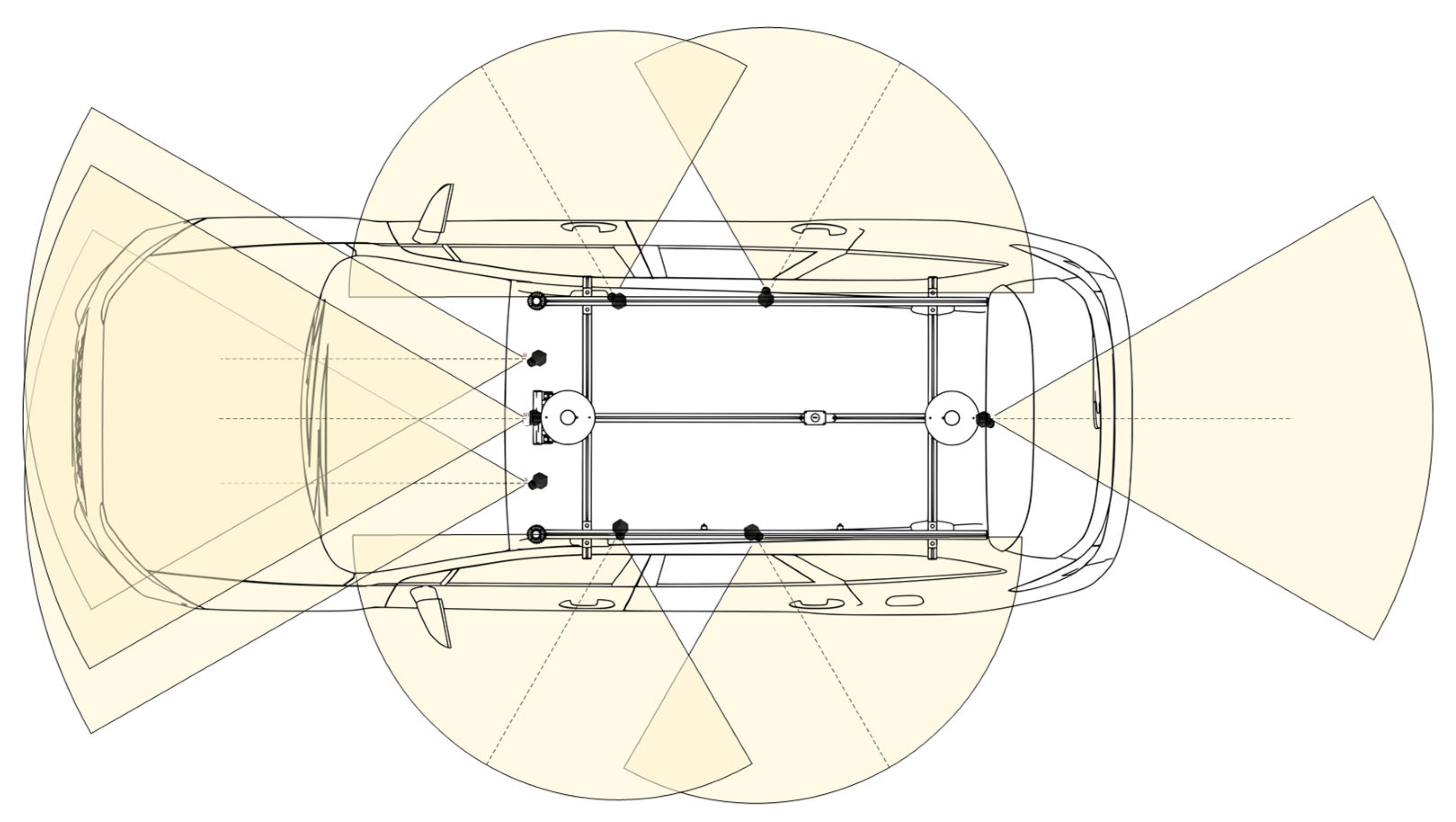
A total of eight high resolution Gigabit Multimedia Serial Link (GMSL) cameras, more specifically four 60° field of view (FOV) and four 120° FOV cameras, are mounted on the roof rack of the AFM. The cameras provide the vehicle with a 360° view of the environment and enable the detection and classification of surrounding objects in real-time. Three 60° FOV cameras point in the driving direction of the vehicle, where one camera is centered in the middle of the vehicle and the remaining two cameras represent a stereo pair. One 60° FOV camera observes the environment at the back of the vehicle. The four 120° FOV cameras are placed on the roof rack such that the observation of the left and right space next to the vehicle is enabled, with two cameras on each side. The camera setup is illustrated in
Figure 11. All cameras are connected to the multi-GPU-accelerated computing system, where the images are processed and forwarded to the neural network-based detection and classification. The cameras are intrinsically and extrinsically calibrated on the multi-GPU-accelerated computing platform with a commercially available software framework [
20].
Two 360° lidar sensors are mounted on the roof rack at the front of the vehicle, which enables a more comprehensive perception of the environment. The lidar information is used to scan the surrounding objects and obstacles and to measure their distances to the vehicle. This enables the generation of a 3D map of the vehicle’s environment, which can be used for a variety of the control algorithms, such as longitudinal and lateral control.
Up to three radar sensors will be integrated in the front of the vehicle which communicate the radar signatures to the ROS2 Computer where a seamless object detection and tracking is carried out. The radar sensors will be integrated though the ROS2 framework and will output two independent scans for both far (~250 ) and near range detections. In addition, the radars will generate both point clouds and object lists, which offer beneficial information for various control applications.
The high precision optical sensor continuously scans the road surface and records various parameters, such as the surface temperature or the water film height.
A total of 12 ultrasonic sensors enables a 360° close range detection of the vehicle surroundings.
3.5. Additional Sensors
In addition to the quantities already mentioned above, there are additional AFM sensors that cannot be clearly assigned to one of the categories. These include:
Current measurements of the power supply system via Hall effect sensors (cf.
Section 2.5).
Real-time Drive Torque and Steering Force Measurement via Strain-gauge Sensors.
A calibrated strain gauge measuring system is installed on the drive shafts and tie rods. Therefore, drive torques and tie rod forces can be measured during driving maneuvers.
Other vehicle quantities that can be read out via the CAN bus of the production vehicle, such as steering wheel angle and torque, accelerator and brake pedal position, high voltage (HV) and low voltage (LV), engine information, tire pressure, fuel level and much more.
A mobile network 4G module allows for uploading the data in real time and connecting to cloud-based applications via an LTE connection. Furthermore, the vehicle network can be accessed to tune the controller’s parameters online or to supervise test drives remotely.
Finally, it should be noted that some quantities, for which high-precision sensors were installed, are already available by (low-cost) sensors installed in the basis vehicle. These include, for example, the vehicle’s center-of-gravity acceleration and angular rates, which are measured by the ESC IMU and can also be read out via the vehicle’s CAN bus. Due to the lower measurement quality, however, these sensor values are only recorded for plausibility purposes.
4. High-Fidelity Vehicle Model
For the AFM, a high-fidelity multi-domain and multi-body-system (MBS) vehicle model is implemented in Modelica. With its help, control systems can be designed and pre-investigated in a simulative way. For the safety concept of test drives, such simulations play a key role since all control functions can be evaluated on the basis of some well-defined maneuvers, thus enabling an early risk assessment. With the help of nonlinear optimization algorithms, the controllers can be designed based on meaningful criteria. Real test drives take place only after the control algorithm has shown its reliability and robustness in the simulations. The risk assessment is completed by documenting the achieved results.
4.1. Modelica Implementation of the AFM
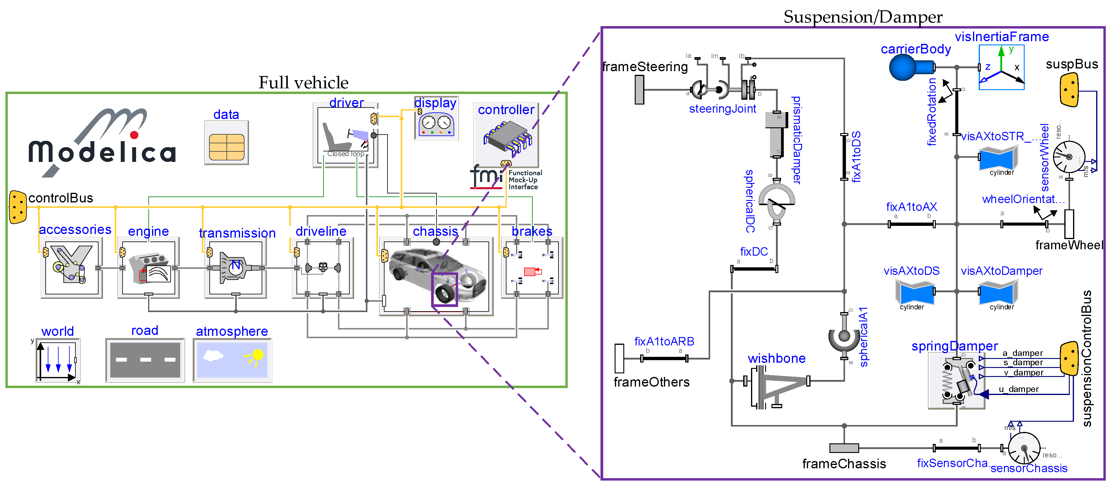
The AFM vehicle model comprises different physical domains, e.g., multi-body mechanics, thermodynamics or electrical systems. Modelica, a powerful object-oriented and formally defined modeling language, is well suited for the implementation of such multi-physics structures [
23]. An overview of the overall model is shown in
Figure 12.
The model contains all main components of the overall modelling problem, in particular the environment, the driver and the full vehicle. These components are briefly introduced below.
The environment is represented by the two blocks
road and
atmosphere on the bottom left side of
Figure 12. The former modeling block considers the track, on which the AFM is controlled, and the road properties such as the slope or the friction coefficient. The latter block considers the simulated weather conditions. With these two blocks, the environment in which the AFM is operated can be modelled sufficiently well.
The
driver block on the top left of
Figure 12 provides the overall model with both open-loop and closed-loop driving maneuvers. This includes standard driving dynamics maneuvers, such as the double lane change or constant radius turning. Through this block, driving maneuvers can be chosen in order to examine specific control methods that have been developed for certain target applications.
The model of the
full vehicle is shown on the left side of
Figure 12. It contains all components of the vehicle. The
drive train and the
brakes are implemented using the DLR PowerTrain Library [
24].
The
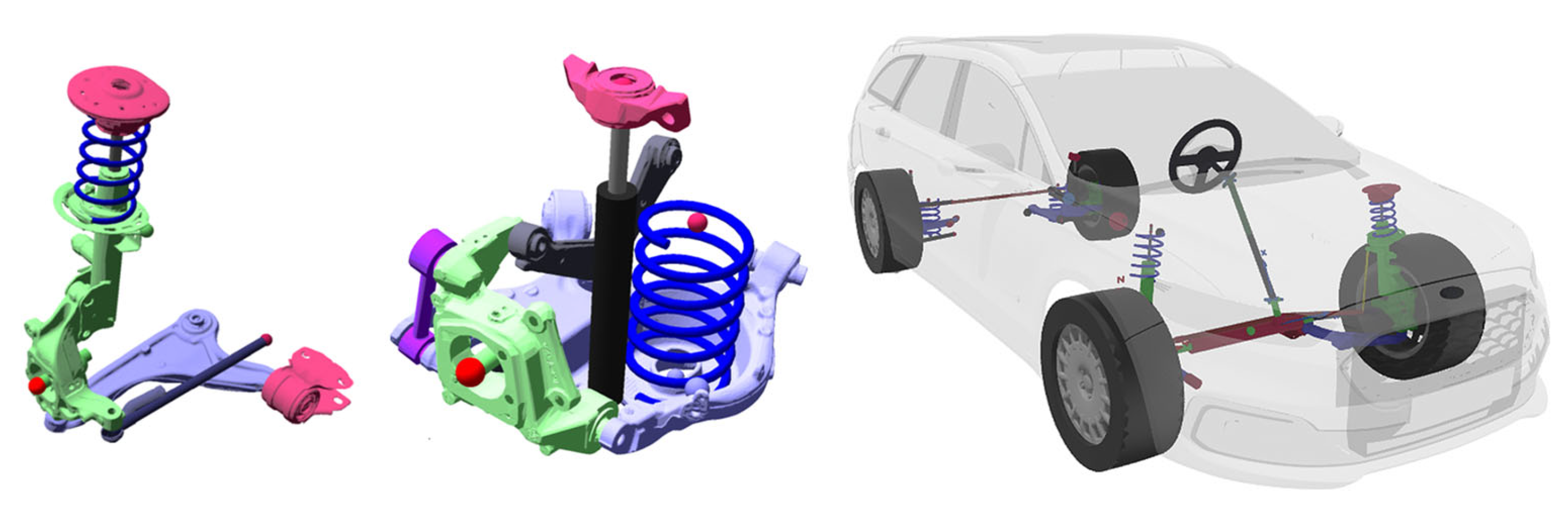
chassis of the AFM is represented by a multi-body model and includes the complete front and rear axles and the four wheels of the vehicle. The axles’ geometry is modeled based on photogrammetric measurements (see
Figure 13 left). In addition, the scanned 3D geometric surface of the components is used to determine the respective centers of mass. The semi-active dampers are modeled via an empirical two-dimensional force map (see Equation (1)). The characteristic maps of the springs and dampers were identified on a Roehrig damper test rig (see damper-force map in
Figure 3). Additionally, the axle model includes subcomponents, such as a steering system or anti-roll bars.
The chassis also includes
tires, which utilize the semi-physical model TMeasy 6.0 [
25]. The consideration of a three-dimensional slip (normalized longitudinal, lateral and turn slip) in TMeasy enables, in particular, a smooth transition from driving to standstill and vice versa.
Figure 13.
AFM’s photogrammetrically scanned front and rear axles (
left-hand side) and the visualization of the high fidelity Modelica model (
right-hand side). The vehicle and its environment are animated using the DLR Visualization 2 Library [
26].
Figure 13.
AFM’s photogrammetrically scanned front and rear axles (
left-hand side) and the visualization of the high fidelity Modelica model (
right-hand side). The vehicle and its environment are animated using the DLR Visualization 2 Library [
26].
In the last two decades, DLR-SR developed a number of Modelica libraries for automotive applications, some of which are used for modeling the AFM [
24,
27,
28]. A number of the above-mentioned models of the DLR-SR automotive libraries have already been cross-validated with other vehicle dynamics simulation tools [
16]. The high-fidelity model of the AFM was simulated on a virtual four-post test rig and matched with a wide variety of road excitation results from real tests (cf.
Section 2.1).
4.2. Use for AI-Based Controller Design
The training data required for the design of AI-based controllers can be generated by the high-fidelity model in Modelica. In virtual test drives, learning data covering a large number of arbitrary driving maneuvers can be created. This eliminates the need for time-consuming real test drives. For supervised-learning methods (and for applications described at the beginning of this section), the model does not necessarily have to be real-time capable, since the training data only have to be generated once to be used afterwards. On the contrary, fast executability is necessary for some other AI methods, such as, e.g., reinforcement learning, in which a controller is learned using a model of the system. In these cases, either only vehicle’s sub-models can be used, e.g., the suspensions in vertical dynamics applications, or a simpler model based on the high-fidelity model can be identified.
The control systems are connected to the vehicle model via a control bus. If the controllers are available as a Modelica implementation, they can be exported to the RCP platform as a functional mockup unit (FMU). If they are implemented in another programming environment such as, for example, Matlab/Simulink, it is possible to integrate them both in Modelica and on the RCP platform as an FMU.
The suitability of the AFM as a data collector and test platform for AI-based control methods is reflected in the possibility to place arbitrary virtual sensors in the vehicle model. This makes it possible, for example, to determine optimal sensor placements or required sensor noise characteristics. Furthermore, the Visualization 2 library [
26] offers the possibility to implement virtual perception sensors in the Modelica model. These include virtual cameras, which record images or videos of the visualized vehicle environment, as well as time-of-flight sensors allowing radar, lidar or ultrasonic sensors to be modeled.
5. AFM—Holistic Application Test Vehicle for AI-Based Control Methods
With its holistic sensor and actuator architecture, the AFM is a test platform with universal application possibilities regarding AI-based vehicle control methods. As already emphasized in
Section 1.1, all application layers for vehicle control functions can be addressed by the AFM (cf.
Figure 2).
First projects and research activities have already been started, where the AFM has proved its strong capabilities.
For the development and testing of novel state estimation methods, the AFM is an excellently suited test platform due to its extensive sensor equipment. These methods can be implemented and evaluated in the vehicle both in a model- and AI-based way. The AFM is used as a test vehicle for an ongoing project to investigate AI-based state estimation methods (so-called virtual sensors) using cloud resources. The sensor data synchronously recorded via the RCP platform forms the basis for computationally expensive data processing, such as training of virtual sensors in the cloud. Moreover, approaches for both detection and compensation of sensor failures can be tested on the AFM.
Investigations of AI-based vertical dynamics control approaches can be tested on the AFM using the semi-active suspension technology [
29]. For example, reinforcement learning methods can be used to determine a control law that addresses both ride comfort and road holding properties. Using simplified models identified on the basis of four-post test rig measurement (see
Section 2.1) or derived from the high-fidelity model (see
Section 4), a good trade-off between the computational performance and the model accuracy for the learning process can be found.
In addition, numerous other projects are already planned. Novel methods for implementing path-following control algorithms (cf. [
30]) can be realized on the AFM thanks to the DBW kit enabling planar motion control. Due to a large number of perception sensors, both static and dynamic obstacles can be included in the path-following control, thus allowing cooperative control algorithms to be investigated on the AFM such as single- and/or multi-agent reinforcement learning (cf. [
31]). By coupling a path-following controller with the AI-based path detection via camera images (see
Section 2.3.2), the AFM demonstrates that multiple application layers of the control pyramid (Application Layer & Motion Execution Layer, see
Figure 2) can be addressed.
The high demand from industry partners and research institutions to use the AFM as a test platform confirms its attractiveness in the context of testing AI-based control algorithms.
6. Conclusions and Outlook
In this work, the AI-for-Mobility research platform for novel AI-based control algorithms was presented. The vehicle’s high-fidelity model, drive-by-wire kit, rich sensor set and high-performance computing platforms enable research for a wide variety of modern AI-based control algorithms, including suspension control, state estimation and vehicle motion control. With the carefully chosen design concept of the vehicle, research can be conducted on all three layers of the control pyramid, more specifically the vehicle application, motion execution and the actuator control layer. With both the GPU-computing platform and the ROS computer operating as a bridge for the environmental sensors, the RCP system serves as a powerful logging platform for numerous sensors integrated in the vehicle. Besides data logging, the RCP system as the central control platform enables simultaneous execution of the developed control algorithms resulting from our research while considering the information provided by the rich sensor set. With the high-performance GPU computing platform, state-of-the-art artificial neural networks can be executed in real-time for a variety of environment perception tasks.
In the future, the AI-for-Mobility vehicle platform will be further developed to ensure that the state-of-the-art requirements for automotive research are being met continuously. This includes replacing the vehicle’s sensors, as well as the state-of-the-art computing platforms with improved future solutions. Furthermore, several different research activities will be carried out on the vehicle, including research on physics-informed neural networks and multi-agent reinforcement learning.


