Featured Application
Stand-alone wind power generator.
Abstract
In this paper, a novel mechanical flux-weakening design of a spoke-type permanent magnet generator for a stand-alone power supply is proposed. By controlling the position of the adjustable modulator ring mechanically, the total induced voltage, i.e., the amplitude of the back EMF vector sum can be effectively adjusted accordingly by the modulation effect. Consequently, the variable-speed constant-amplitude voltage control (VSCAVC) with a large speed range can be achieved. Compared to the electrical flux-weakening method, the mechanical flux-weakening method is easier to operate without the risk of PM demagnetization. The analytical model is presented, and the operation principles are illustrated. To analyze the performance of different combinations of stator/rotor pole pairs, four cases are optimized and analyzed using the finite element method for comparison. The characteristics of VSCAVC are analyzed.
1. Introduction
Currently, more than 1.1 billion people are not accessible to the electrical grid. Most of these people live in rural areas or offshore islands, and expanding the power grid to these remote areas is neither economical nor effective [1]. A stand-alone wind energy generating system is a perspective method of providing electricity to regional grids and effectively solving the above-mentioned issues. Among all wind generators, the permanent magnet (PM) generator, with its high torque density and efficiency, is the most favored electrical generator. However, as the wind speed is not constant, the output voltage would remain constant if no control is introduced. For conventional PM generator, a fully rated matrix converter may be needed, which may be expensive and complex to control. To effectively control the output voltage, flux-weakening control is widely used for PM machines. Numerous methods of flux weakening have been proposed in the past 20 years, which can mainly be classified into two categories: Electrical and mechanical techniques.
For electrical flux-weakening techniques, the most conventional method is to inject a negative d-axis current, which produces a field that opposes the original PM field. This technique is relatively suitable for machines with a high saliency ratio, i.e., the difference between the d-axis and q-axis inductance is significant [2,3,4]. However, additional external inductors are required for a machine with a small saliency ratio if the negative d-axis current injection flux-weakening technique is used [5], which adds more complexity to the system. In addition, over-injection of negative d-axis current may cause the demagnetization of the PMs. Moreover, for the generating system, using this method requires two sets of windings, and the coupling effect between two windings needs further consideration. Another electrical flux-weakening technique uses the variable flux method, which can be further categorized into hybrid excitation type and mnemonic material type. Hybrid excitation type machines generally need an extra set of DC excitation winding, which could enhance or weaken the field by injecting positive or negative DC. Typically, the DC excitation flux path is parallel to the PMs to prevent demagnetization of the PMs [6,7,8,9]. Nevertheless, two sets of windings are needed for this type of machine. The mnemonic material type machine, also known as a memory machine, uses the Alnico PM for parts or all excitations of the machine. The Alnico PM has low coercivity; therefore, its magnetization direction can be easily adjusted using excitation pulses in the d-axis direction of Alnico PMs [10,11,12]. Nevertheless, the structure of the memory machine needs to be specially designed to prevent the interaction between the field generated by the armature and Alnico PMs, which is relatively complex. Otherwise, the unwanted demagnetization of Alnico PMs may occur.
With the electrical methods, considerable amounts of current would have to be consumed to weaken the strong flux from the PMs or maintain the excitation flux, which results in an efficiency decrease, while also having the risk of PM demagnetization. Conversely, mechanical methods adjust the linked flux by manipulating the position of certain machine parts, which avoids the current consumption. Therefore, mechanical methods might be more suitable for the application of a stand-alone generator, where a wide speed range and constant working condition is required. Mechanical flux-weakening techniques can be categorized into two categories: Self-actuated type and actively controlled type [13]. The self-actuated type generally uses the rotating speed-related force and the spring system to realize the movement of flux-adjusting elements by themselves. In [14], a spoke IPM machine with movable ferromagnetic yokes connected with the spring system is proposed. The yoke provides a leakage path that can move closer to the inner rotor rim when the centrifugal force is large, thus achieving flux regulation by itself. In [15], a double-rotor PM machine is proposed in which one rotor is directly connected to the shaft, and another rotor rotates with displacement relative to the shaft by the spring system. Depending on the rotational speed, two rotors will have a corresponding displacement angle. Therefore, the total flux linkage, which is the vector sum of two flux linkages, is adjustable. However, all the self-actuated mechanical flux-weakening methods cannot be controlled manually, which may be problematic when emergencies occur. Moreover, the spring system is difficult to calibrate and requires regular maintenance. The actively controlled mechanical flux-weakening method uses an external force to control the flux-adjusting elements. A switched flux machine with movable iron pieces outside of the stator that is controlled independently is introduced in [16]. When the iron piece is moved to the closed position, the PM flux is short-circuited, reducing 60% of the flux linkage compared to the conventional switched flux machine. An actively controlled version of the axial-flux PM machine in [15] is proposed in [17], and a radial-flux version is presented in [18], which has the minimum flux linkage in the equilibrium position and the maximum flux linkage in the aligned position.
In [19], a dual-rotor PM machine based on bidirectional flux modulation is proposed for the standalone DC power supply. This design requires a conventional winding whose pole pair number is equal to the outer rotor, and a modulation winding. Two sets of windings are connected in series as their frequencies are the same. The inner rotor is connected to the servo motor. Therefore, the inner PM flux linkage vector is adjustable and the sum of modulated vector and the outer PM vector, namely the total flux linkage, is controllable. This active-controlled mechanical flux-weakening method suits the machine with a small saliency ratio. Nevertheless, two sets of windings are needed, which have the following shortcomings: First, two pairs of windings have different coil pitches, which are relatively complex to manufacture; second, the turn numbers of two pairs of windings are different for reaching the maximized flux controlling range.
This paper proposes a novel mechanical flux-weakening spoke-type PM generator. In only one set of windings, all three working harmonics have the same frequency, which can be added as vectors based on the flux modulation principle. By adjusting the modulator ring within a certain angle, the flux can be effectively controlled without the risk of PM demagnetization, and the variable-speed constant-amplitude voltage control (VSCAVC) can be achieved. A commercial servo system using the position control mode is sufficient for dynamic performance, which is also cost-efficient, robust, and easy to control. The principles of flux controlling and working harmonic selection are introduced. To investigate the influence of the pole pair number and the performance of the novel design, four cases with different rotor poles and winding configurations, i.e., 12/7, 12/8, 12/10, and 12/11 stator/rotor pole pair combinations, have been designed, optimized, and compared. Finally, the 12/7 design is selected, and its VSCAVC characteristics are analyzed.
2. Machine Configuration and Operating Principle
2.1. Machine Configuration
The configuration of the proposed generating system is shown in Figure 1. The designed model consists of a stator, an adjustable modulator ring, and a rotor. A three-phase seven-pole-pair winding is placed inside twelve stator slots. A set of seven-pole-pair PMs is placed on the rotor. The PMs on the rotor are tangentially magnetized for flux concentration. The rotor is connected to the wind turbine through a gearbox. A twelve-pole-pair adjustable modulator ring is placed between the stator and rotor. The modulator is connected to the servo motor, which can be adjusted within a limited angle for flux weakening.
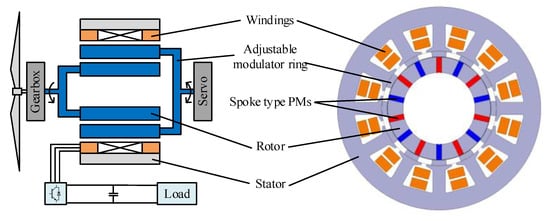
Figure 1.
Configuration of the mechanical flux-weakening design of the PM generating system.
2.2. Flux Modulation Principles
The parameter definition of the analytical model is shown in Figure 2. Suppose that the number of stator slots, the number of pole pair of the rotor, and the number of pole pair of modulators are , , and .
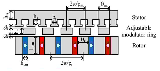
Figure 2.
Parameter definition of the analytical model.
When neglecting the magnetic resistance of the iron core, the slotting effect of the stator core, and the flux leakage, the magnetic circuit of one pole can be given in Figure 3 [20]. The magnetomotive force (MMF) of one piece of PM can be expressed as follows:
where is the coercivity of the PM, and is the thickness of the PM, as shown in Figure 2. The resistance of the PM airgap of one pole and the outer airgap of one pole can be given as follows:
where is the magnetic permeability of the vacuum, is the relative magnetic permeability of the PM material, and denote the length of the inner and outer airgap, is the thickness of the iron core of one pole, is the radius of the airgap, and is the stack length. The flux of one pole can be calculated as follows:
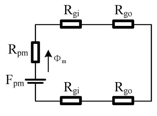
Figure 3.
Magnetic circuit of one pole.
The amplitude of one pole’s MMF in the airgap can be expressed as follows:
The waveform of the rotor in the airgap is shown in Figure 4, which can be expressed as follows:
where is the magnitude of the i-th rotor PM MMF component, which can be further derived as follows:
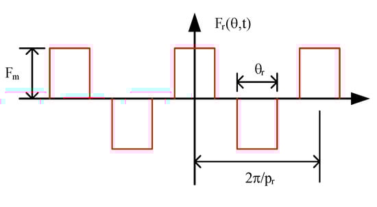
Figure 4.
MMF waveform of the rotor PMs.
The permeance of the modulator is presented in Figure 5, which can be expressed as follows:
where is the mechanical initial phase angle of the modulator, is the magnitude of the modulators’ average permeance component, and is the magnitude of the j-th permeance component, which can be expressed as follows:
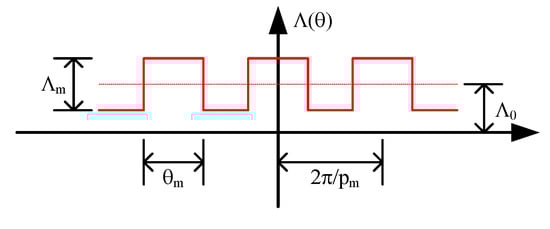
Figure 5.
Permeance waveform of the modulator.
The airgap flux density produced by the rotor PMs and the modulator teeth can be deduced by multiplying (7) and (9) and is expressed as follows:
where
For convenience in further analysis, the coefficients of the components from (12) to (14) are sorted and listed in Table 1. Harmonic components can be categorized into the following three types:

Table 1.
Coefficients of the PM harmonic components in the airgap.
- Type A components are unmodulated stationary components.
- Type B1 components are modulated components that rotate in the same direction as type A and can be adjusted mechanically.
- Type B2 components are modulated components that rotate in the opposite direction from type A and can be adjusted mechanically.
The flux linkage of one phase can be calculated as follows:
where is the number of turns in one phase, is the corresponding distribution factor, and is the corresponding coil pitch. By substituting (12)–(14) into (15), the components of the three types can be expressed as follows:
The back EMF of one phase can be calculated as follows:
By substituting (16)–(18) into (19), the components of three types can be expressed as follows:
where , , and are the amplitudes of , , and , respectively. All can be given as the following expression:
where is the winding factor, is the pitch factor, is the corresponding angular speed, and is the corresponding amplitude of the flux density. Therefore, , , and can be expressed as follows:
2.3. Working Harmonic Selection
The amplitude of the harmonics in type B is lower than type A with the same under the flux modulation effect. Therefore, to obtain higher back electromotive force (EMF) and associated electromagnetic torque, the number of the pair of winding poles should be designed according to the harmonic order of type A. According to (8), the highest value of can be obtained when . Therefore, the pair number of the winding should be designed as follows:
Under the abovementioned winding design, all the harmonics in types A and B with are utilized as working harmonics. As all three types of working harmonics have the same frequency, the back EMF of the three types of harmonics can be added together.
According to (10), the highest value of can be obtained when . Therefore, the harmonics with in type B are used as the main working harmonics.
The slot angles of types A, B1, and B2 harmonics can be calculated as follows:
To fully utilize all three types of working harmonics, the number of the modulation segments should be as follows:
Under (31), the slot angle of type B harmonic components are as follows:
From (28), (32), and (33), the following can be observed:
- 4.
- First, is equal to , which indicates that types A and B1 have the same winding arrangement sequence.
- 5.
- The sum of and is , which indicates that the winding arrangement sequence for the flux density components of type B2 is identical to those of types A and B1, but in the reverse direction.
Since the back EMF frequency of types A, B1, and B2 is the same, all three types of harmonics can generate the back EMF in the same winding set.
Taking the proposed machine in Figure 1 as an example, , . Their armature back EMF vectors with the rotating directions are shown in Figure 6. In Figure 6b, we can observe that the back EMF vector sequence and the rotating direction of type B2 are different from types A and B1, which can eventually become the same winding arrangement as types A and B1 by vertical flipping. As the frequency of three types of working harmonics is the same, all three types can produce a back EMF in the same set of winding. We can conclude the following:
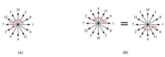
Figure 6.
Armature back EMF vectors of the proposed machine with the rotating direction. (a) ; (b) .
- 6.
- All three types of working harmonics have the same distribution factor and pitch factor, i.e.,
- 7.
- The coil pitch of types A and B1 is opposite from type B2, i.e.,
- a .
- Flux controlling principle
Total back EMF can be derived as the vector sum of the back EMF of types A, B1, and B2. From (24)–(26), we can conclude the vector graph of the back EMF, as shown in Figure 7a. Vector is fixed, whereas and can rotate in the opposite direction. The total back EMF can change along the blue oval-shaped trajectory. When the electrical initial phase angle of the modulator , the components of types A, B1, and B2 have the same direction and the total back EMF reaches the maximum at this position, as shown in Figure 7b. When , both types B1 and B2 have the opposite direction from type A, and the total back EMF reaches the minimum at this position, as shown in Figure 7c. Therefore, although types B1 and B2 have different rotation directions, both type B components positively contribute to the control of the back EMF.
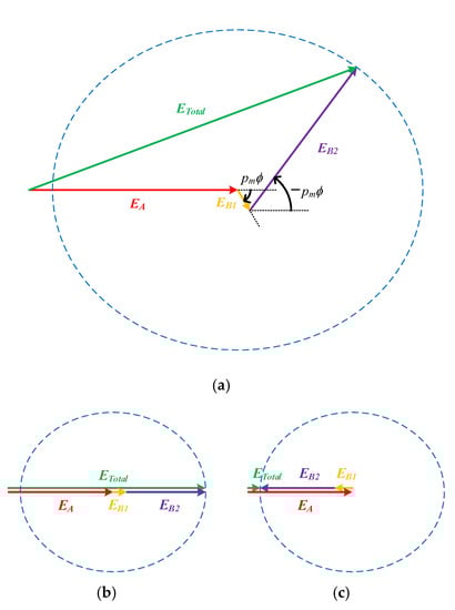
Figure 7.
Back EMF vector graph. (a) Showing diagram; (b) maximum total back EMF position (); (c) minimum total back EMF position ( ).
By adjusting the electrical initial phase angle of the modulator from to , the total back EMF can vary with the range from to . Therefore, the total back EMF amplitude can be effectively controlled.
From (25) and (26), it should be observed that the amplitude of is significantly smaller than . As the rotating speed of is times higher than ; therefore, plays a major role in the control of the back EMF. To obtain the widest control range of the back EMF, the amplitude of should be close to . From (24) and (26), we could observe that is smaller than , as is always smaller than . Therefore, should be larger than , and the pole pair number of rotor should follow:
3. Electromagnetic Performances Comparison and Analysis
3.1. Optimization Design
As mentioned in (36), four feasible stator/rotor pole pair combinations, i.e., the 12/7, 12/8, 12/10, and 12/11 have been designed for comparison. Four models are optimized independently by the nondominated sorted genetic algorithm-II (NSGA-II). The common design parameters of all models are listed in Table 2 and the variables to be optimized are listed in Table 3. The optimization goals are to maximize the output torque density and minimize the maximum torque ripple ratio with the armature current density of 6 A/mm2. and are defined as follows:
where is the average torque of the outer rotor, and is the volume of the electromagnetic part of the machine.
Table 2.
The common design parameters of the optimized models.
Table 3.
The optimizing variables of models.
The optimization process flow chart is shown in Figure 8. The optimization in this paper has 20 generations, with 100 designs in each generation. The Pareto fronts of four designs are presented in Figure 9. The designs indicated by the red arrow in Figure 9 are the final optimized designs. All final designs have the highest torque density when the torque ripple is below 10%.
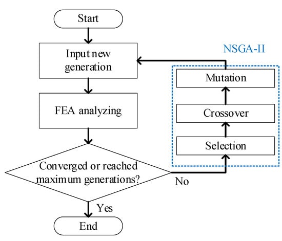
Figure 8.
The optimization flowchart using FEA and NSGA-II.
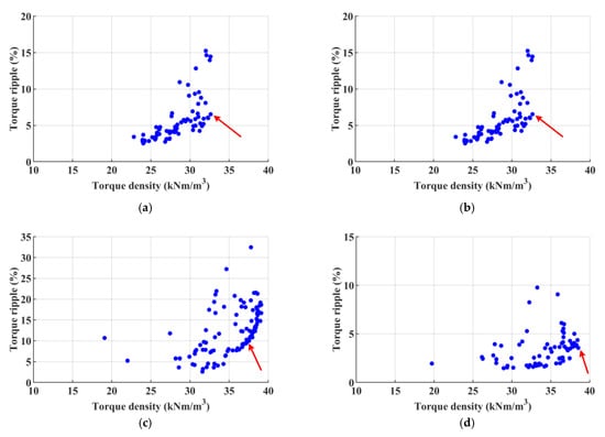
Figure 9.
The Pareto fronts of the GA. (a) 12/7; (b) 12/8; (c) 12/10; (d) 12/11.
3.2. Torque Performance
The curve of torque production and torque density per volume with different current densities under the rated speed is shown in Figure 10. At the rated current density, the 12/11 design has the highest torque density, which is 38.4 kNm/m3. The torque density of the 12/7 design is 32.1 kNm/m3, which is 16% lower than the 12/11 design. However, it is worth mentioning that although the 12/7 design torque density is the lowest among the four cases, its torque density is still considered high compared to conventional PM machines, which are generally under 20 kNm/m3.
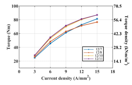
Figure 10.
The curve of current density vs. torque and torque density.
3.3. Harmonic Distribution
The calculated flux density distribution and the fast Fourier transform (FFT) analysis in the airgap of four cases are shown in Figure 11. It can be observed that types A and B2 components are significantly higher than the other harmonics. To quantitatively analyze the contribution of each type of harmonic component, the back EMF contribution of the main working harmonics is calculated and shown in Table 4 using the analytical method based on (23). The amplitudes of types A and B2 components are significantly higher than type B1, which agrees with the FEM results. The amplitude of type B2 is significantly higher than type B1, which also agrees with the operation principles.
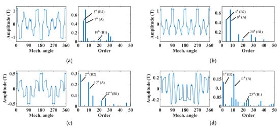
Figure 11.
The flux density distribution and their FFT analysis in the airgap of four cases. (a) 12/7; (b) 12/8; (c) 12/10; (d) 12/11.
Table 4.
Contribution of the harmonic components to back EMF by the analytical method.
In Table 4, it can be observed that for 12/7 design, the amplitude of type A induced voltage is almost equal to type B (i.e., the sum of the amplitude of types B1 and B2). For 12/8, 12/10, and 12/11 designs, their type B amplitude is higher than type A.
3.4. Voltage Regulation Ratio
The back EMF vector trajectory of four cases using FEM is shown in Figure 12, and the curves of back EMF amplitude with the change in the initial phase angle are shown in Figure 13.
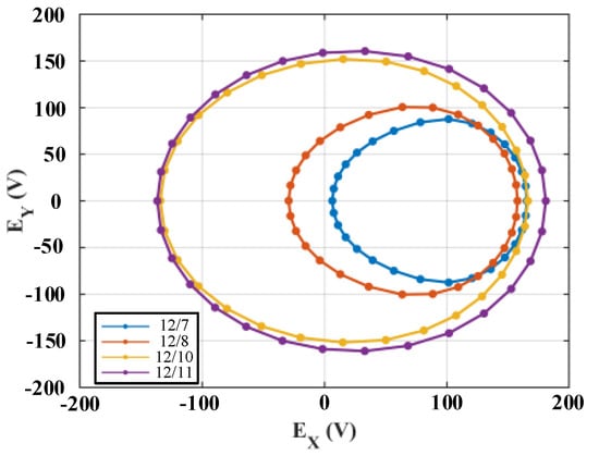
Figure 12.
Back EMF vector trajectory of four cases by FEM.
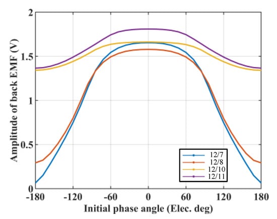
Figure 13.
The curves of back EMF amplitude vs. the initial phase angle.
In Figure 13, it can be observed that the 12/7 design has relatively the best flux controlling ability, as its types A and B component’s amplitude are the closest among all four cases, as shown in Table 4. The 12/8 design is similar to the 12/7 configuration with notable drawbacks: Its type B component’s amplitude is higher than the type A component, which makes the vector trajectory have a specific portion on the left side of y-axis, as shown in Figure 12. For the 12/10 and 12/11 designs, in Table 4, it can be observed that the amplitude of the type B component is significantly higher than type A. As a result, although the type B component vector can rotate, the variation of the total back EMF amplitude is significantly smaller, which causes these two designs to have relatively weak flux controllability, as shown in Figure 13.
To value the ability of flux control, the voltage regulation ratio (VRR) is introduced in this paper. The voltage regulation ratio of the analytical method and FEM is summarized and compared in Table 5, where and denote the back EMF amplitude of types A and B components, and and denote the maximum and the minimum of the back EMF amplitude. The voltage regulation ratio is defined as follows:
Table 5.
Analytical and FEM results of back EMF voltage regulation ratio.
The larger the VRR, the better the flux controllability that the design has. In Table 5, it can be found that the results of the analytical method agree with the results of the FEM, thus proving the validity of the operating principles. The VRR of the 12/7 design is significantly higher than its counterparts.
From the above analysis, a design guideline can be given: The best flux controllability can be obtained when the rotor pole pair number is slightly higher than half of the stator teeth number.
3.5. Overall Comparison
The overall comparison of four cases is listed in Table 6. The torque variation range is signifcantly smaller than the flux voltage regulation ratio. In Table 6, the 12/7 design has the best flux voltage regulation ratio, and has a torque density of over 20 kNm/m3. Therefore, the 12/7 design is selected as the best design among the four cases.
Table 6.
Overall comparison of the four cases.
4. VSCAVC Characteristics of the Selected Design
The design parameters and dimensions of the selected optimized 12/7 model are shown in Table 7.
Table 7.
Design parameters and dimensions of the selected model.
The VSCAVC steady-state characteristics of the 12/7 design are shown in Figure 14. The generator operates at a speed of 500 rpm in the beginning, and the initial phase angle of the modulator is fixed at 0°. The amplitude of the voltage is 91 V. When the generator runs at 1000 and 1500 rpm to maintain amplitude, the modulator simultaneously adjusts to 108° and 120° in electrical degree. The simulation shows that the design model has good control over the voltage amplitude. The current curve is sinusoidal, and the torque curve is smooth, with a ripple under 5% of the average.
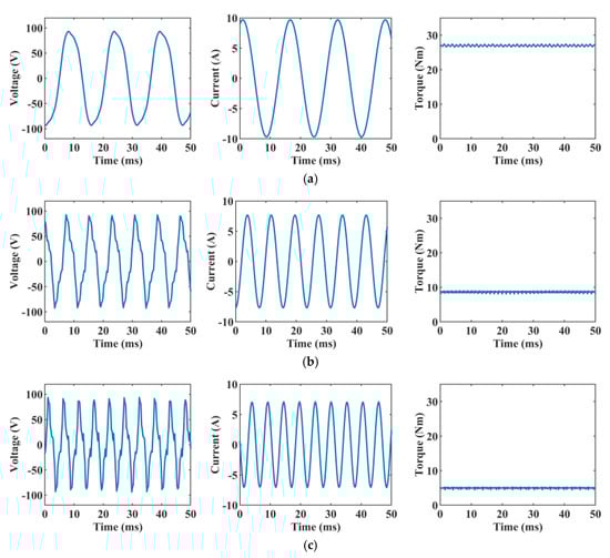
Figure 14.
VSCAVC steady-state characteristics of the selected 12/7 design with different rotor speeds and initial phase angles (in electrical degree). (a) 500 rpm, ; (b) 1000 rpm, ; (c) 1500 rpm, .
From (19), the back EMF can be pre-determined by the initial phase angle and rotating speed of the rotor, as shown in Figure 15. A lookup table can be made, which can be used for controlling. The dynamic model and the control performances of the selected model will be discussed in the future.
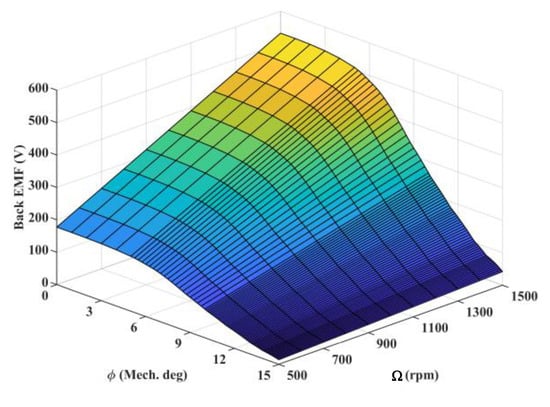
Figure 15.
The relationship of back EMF, initial phase angle, and rotating speed of the rotor.
5. Conclusions
This paper presents a novel mechanical flux-weakening design of spoke-type permanent magnet generator for a stand-alone power supply. The back EMF of all three working harmonics can obtain the same frequency and can be summed as vectors. By controlling the position of the adjustable modulator ring and using the modulation effect, the sum of the back EMF vector can be regulated, and the flux weakening can be smoothly achieved. With special pole pair selection, only one set of windings is needed, which simplifies manufacturing. Compared to conventional PMSMs, the mechanical method can have a wide range of flux weakening without the risk of PM demagnetization. VSCAVC can be applied to this machine.
The analytical model and operating principles are illustrated in this paper, and four optimized cases with different stator/rotor pole pairs are compared to show the advantageous performance of the proposed design. The 12/7 design with a voltage regulation ratio of 96.1% and a torque density of 32.1 kNm/m3 is selected. The VSCAVC characteristics of the 12/7 design are analyzed, showing the outstanding performance of the selected design.
Author Contributions
Investigation, methodology, writing—original draft preparation, M.J.; supervision, writing—review and editing, project administration, funding acquisition, S.N. All authors have read and agreed to the published version of the manuscript.
Funding
This research was funded by the Hong Kong Research Grants Council, Hong Kong, under Project PolyU 152109/20E.
Institutional Review Board Statement
Not applicable.
Informed Consent Statement
Not applicable.
Data Availability Statement
Not applicable.
Conflicts of Interest
The authors declare no conflict of interest.
References
- Almeshqab, F.; Ustun, T.S. Lessons learned from rural electrification initiatives in developing countries: Insights for technical, social, financial and public policy aspects. Renew. Sustain. Energy Rev. 2019, 102, 35–53. [Google Scholar] [CrossRef]
- Jahns, T.M. Flux-weakening regime operation of an interior permanent-magnet synchronous motor drive. IEEE Trans. Ind. Appl. 1987, 4, 681–689. [Google Scholar] [CrossRef]
- Schiferl, R.F.; Lipo, T.A. Power capability of salient pole permanent magnet synchronous motors in variable speed drive applications. IEEE Trans. Ind. Appl. 1990, 26, 115–123. [Google Scholar] [CrossRef]
- Jahns, T.M.; Kliman, G.B.; Neumann, T.W. Interior permanent-magnet synchronous motors for adjustable-speed drives. IEEE Trans. Ind. Appl. 1986, 4, 738–747. [Google Scholar] [CrossRef]
- Soong, W.L.; Staton, D.A.; Miller, T.J. Design of a new axially-laminated interior permanent magnet motor. IEEE Trans. Ind. Appl. 1995, 31, 358–367. [Google Scholar] [CrossRef]
- Amara, Y.; Vido, L.; Gabsi, M.; Hoang, E.; Ahmed, A.H.B.; Lecrivain, M. Hybrid excitation synchronous machines: Energy-efficient solution for vehicles propulsion. IEEE Trans. Veh. Technol. 2008, 58, 2137–2149. [Google Scholar] [CrossRef]
- Amara, Y.; Hlioui, S.; Belfkira, R.; Barakat, G.; Gabsi, M. Comparison of open circuit flux control capability of a series double excitation machine and a parallel double excitation machine. IEEE Trans. Veh. Technol. 2011, 60, 4194–4207. [Google Scholar] [CrossRef]
- Wang, Y.; Deng, Z. Parallel hybrid excitation machines and their control schemes for dc generation system. IET Electr. Power Appl. 2012, 6, 669–680. [Google Scholar] [CrossRef]
- Hsu, J.S. Direct control of air-gap flux in permanent-magnet machines. IEEE Trans. Energy Convers. 2000, 15, 361–365. [Google Scholar] [CrossRef]
- Ostovic, V. Memory motors. IEEE Ind. Appl. Mag. 2003, 9, 52–61. [Google Scholar] [CrossRef]
- Yu, C.; Chau, K.; Liu, X.; Jiang, J. A flux-mnemonic permanent magnet brushless motor for electric vehicles. J. Appl. Phys. 2008, 103, 07F103. [Google Scholar] [CrossRef]
- Yu, C.; Chau, K. Design, analysis, and control of dc-excited memory motors. IEEE Trans. Energy Convers. 2010, 26, 479–489. [Google Scholar] [CrossRef]
- Cekani, J.; Capponi, F.G.; De Donato, G.; Caricchi, F. Mechanical flux weakening methods for the achievement of a very wide constant power speed range in automotive applications. IEEE J. Emerg. Sel. Top. Power Electron. 2021, 10, 3443–3458. [Google Scholar] [CrossRef]
- Elloumi, N.; Bortolozzi, M.; Masmoudi, A.; Mezzarobba, M.; Olivo, M.; Tessarolo, A. Numerical and analytical approaches to the modeling of a spoke type ipm machine with enhanced flux weakening capability. IEEE Trans. Ind. Appl. 2019, 55, 4702–4714. [Google Scholar] [CrossRef]
- Caricchi, F.; Crescimbini, F.; Capponi, F.G.; Solero, L. Permanent-magnet, direct-drive, starter/alternator machine with weakened flux linkage for constant-power operation over extremely wide speed range. In Proceedings of the Conference Record of the 2001 IEEE Industry Applications Conference, 36th IAS Annual Meeting (Cat. No. 01CH37248), Chicago, IL, USA, 30 September–4 October 2001; Volume 3, pp. 1626–1633. [Google Scholar]
- Zhu, Z.Q.; Al-Ani, M.; Liu, X.; Lee, B. A mechanical flux weakening method for switched flux permanent magnet machines. IEEE Trans. Energy Convers. 2014, 30, 806–815. [Google Scholar] [CrossRef]
- Capponi, F.G.; Terrigi, R.; Caricchi, F.; Del Ferraro, L. Active output voltage regulation for an ironless axial-flux pm automotive alternator with electromechanical flux weakening. IEEE Trans. Ind. Appl. 2009, 45, 1785–1793. [Google Scholar] [CrossRef]
- Kulan, M.C.; Baker, N.J.; Turvey, S. Split rotor concept for permanent magnet electrical machines. In Proceedings of the 2019 IEEE International Electric Machines & Drives Conference (IEMDC), San Diego, CA, USA, 12–15 May 2019; pp. 700–707. [Google Scholar]
- Wang, Y.; Niu, S.; Fu, W. A novel dual-rotor bidirectional flux-modulation pm generator for stand-alone dc power supply. IEEE Trans. Ind. Electron. 2018, 66, 818–828. [Google Scholar] [CrossRef]
- Cheng, M.; Han, P.; Hua, W. General airgap field modulation theory for electrical machines. IEEE Trans. Ind. Electron. 2017, 64, 6063–6074. [Google Scholar] [CrossRef]
Disclaimer/Publisher’s Note: The statements, opinions and data contained in all publications are solely those of the individual author(s) and contributor(s) and not of MDPI and/or the editor(s). MDPI and/or the editor(s) disclaim responsibility for any injury to people or property resulting from any ideas, methods, instructions or products referred to in the content. |
© 2023 by the authors. Licensee MDPI, Basel, Switzerland. This article is an open access article distributed under the terms and conditions of the Creative Commons Attribution (CC BY) license (https://creativecommons.org/licenses/by/4.0/).