Article

The Nature of Metal Artifacts in X-ray Computed Tomography and Their Reduction by Optimization of Tomography Systems Parameters

by
Sergey Pavlovich Osipov
1,
Sergei Vladimirovich Chakhlov
1,
Vadim Yurevich Zhvyrblia
1,*,
Dmitry Andreevich Sednev
1,
Oleg Sergeyevich Osipov
2 and
Eugeny Yurevich Usachev
3
1
National Research Tomsk Polytechnic University, Lenina Av., 30, 634050 Tomsk, Russia
2
Medialooks, Alexander Nevsky Av., 59, 236016 Kaliningrad, Russia
3
Diagnostika-M LLC, Volgogradsky Av., 42, 109316 Moscow, Russia
*
Author to whom correspondence should be addressed.
Appl. Sci. 2023, 13(4), 2666; https://doi.org/10.3390/app13042666
Submission received: 26 January 2023 / Revised: 14 February 2023 / Accepted: 16 February 2023 / Published: 19 February 2023
(This article belongs to the Special Issue Application of X-ray Computed Tomography)

Abstract

:
A significant gap in the known methods for assessing the levels of metal artifacts in X-ray computed tomography and approaches to their reduction is an almost complete disregard for the physical nature of this artifact—the proximity to zero of radioscopic transparency. The proposed work fills this gap. A mathematical model has been developed for evaluating metal artifacts in X-ray computed tomography as applied to the geometry of a parallel beam. The simulation model was transformed into an algorithm, and a Mathcad program was designed to simulate images of the internal structure of the test objects. The algorithm for estimating the studied artifact includes the stages of generating sinograms and estimating the distributions of the linear coefficient over the sections of the object based on the back projection method with filtering. The efficiency of the metal artifacts simulation algorithm is demonstrated in the example of symmetric and asymmetric objects with low- and high-density inclusions and inclusions from materials with high atomic number values. The possibility of reducing metal artifacts with the help of a rational choice of the maximum energy of X-ray radiation and the ADC bit depth is illustrated. For example, for an aluminum cylinder 200 mm in diameter with a central cylindrical cavity 80 mm in diameter, cylindrical inserts 12 mm in diameter with material densities from 1.5 g/cm3 to 10 g/cm3, and effective atomic numbers of materials from 13 to 47, the numerical simulation method proved the following: it is practically unattainable to significantly reduce the level of metal artifacts by increasing the ADC capacity to the maximum X-ray energy of 160 keV; the desired effect is achieved by simultaneously increasing the maximum X-ray energy to 225 keV and the ADC capacity to 24 or 32; increasing the maximum X-ray energy from 160 keV to 225 keV leads to an increase in the energy absorbed in the material of the test object by 26%. The results of this research can be used at the design stage of X-ray computed tomography systems designed to control objects with fragments of low radiation transparency.

1. Introduction

Problems related to the influence of artifacts on the quality of evaluation of the internal structure of test objects (TOs) in X-ray computed tomography (CT) continue to be one of the most important areas of research in tomography [1,2,3,4,5]. This is primarily due to the expansion of the range of objects that have not previously been tested using the X-ray CT method. Moreover, the noted expansion occurs not only along the line of complication of the structure of the test objects, but also an increase in their size, an increase in the density and effective atomic number of the materials of their structural fragments. All of the above leads to a decrease in the transparency of the test objects for X-ray radiation and, consequently, an increase in the influence of metal artifacts on the quality of testing objects by X-ray CT [6,7,8]. Therefore, the role of studies related to the reduction of the contribution of metal artifacts to the bias in estimates of the distributions of informative parameters over the TO slice (volume) increases [8,9,10,11]. Here, informative parameters are the Hounsfield number, linear attenuation coefficient (LAC) of radiation, density, and effective atomic number. In connection with the transition of the X-ray CT method from a means of visualizing the TO internal structure to a measuring tool, which has been outlined in recent decades [12,13], the density and effective atomic number can be considered the prevailing informative parameters.
It was noted in [14] that the design of X-ray CT systems is based on the principles of physical and technical feasibility. In relation to X-ray CT, the principle of physical feasibility is understood as the presence of physical laws that connect the set of measured projections (sinograms) with the distribution of density (density and effective atomic number) over the TO slice (volume) using mathematical relationships. Moreover, this relationship should be one-to-one. It was noted in [15] that the physical reasons include the differences between the actual laws of emission, interaction, and registration of photon radiation from some idealized laws and models, for example, the model of a plane-parallel beam of mono-energetic radiation. The principle of technical feasibility indicates the availability of technical capabilities for the implementation of the physical principle in order to obtain estimates of the distributions of the required informative parameters over the TO slices or its entire volume with the calculation time and accuracy specified by the consumer. Accordingly, it is possible to divide, with a certain degree of conditionality, the entire set of reasons causing the appearance of artifacts in the X-ray CT into physical and technical factors.
The purpose of the proposed study is to clarify the nature of metal artifacts in computed tomography and to substantiate, by simulation modeling, the possibility of correcting metal artifacts in the final images of CT using a rational choice (optimization) of the technical parameters of the analyzed systems.
It is necessary to solve several problems to achieve the above goal: to develop a mathematical model for evaluating metal artifacts in X-ray computed tomography in relation to the control of objects with fragments of low radiation transparency; to carry out a cycle of computational experiments to study symmetric and asymmetric objects with low and high-density inclusions and with inclusions from materials with high atomic numbers using the X-ray CT method; to identify the influence of which main technical (physical) factors on the level of metal artifacts is the most significant; to illustrate the possibility of reducing metal artifacts by a rational choice of significant parameters. Here, radiation transparency is understood as the transparency of objects to X-rays [6,7].
Let us make a number of necessary explanations concerning the stated goal of research and the tasks for its implementation. Let us divide these explanations into three main groups: mathematical models for evaluating metal artifacts in X-ray CT; ways to reduce metal artifacts in CT; the main physical and technical factors affecting the level of metal artifacts in the X-ray CT; the technical possibility of solving the problems of designing CT systems for testing TO with fragments with low radiation transparency. Note that these groups are related to each other. Let us dwell on them in more detail.
1. In the scientific literature, many mathematical models of X-ray CT of varying degrees of complexity are described with a sufficient degree of detail, for example, [14,16,17,18,19,20]. In [15], a number of general requirements for mathematical models of X-ray CT were formulated. Such requirements include simplicity, high performance, clarity, and variability in the description of the structures of control objects. It is necessary to add the ability to adapt to physical and technical influences (disturbances) to expand the capabilities of mathematical models. These requirements are fully met by the mathematical model from [14]. The advantage of this model is the simplicity of its implementation in the system of mathematical calculations MathCad. This is due to the fact that the MathCad language is exceptionally close to the natural mathematical language [21]. The MathCad system is widely used in the development of methods and tools for nondestructive testing [14,15,22,23,24]. Based on the foregoing, mathematical models from [14,15] can serve as the basis for a model for assessing metal artifacts and the degree of their correction when changing the parameters of X-ray CT systems.
2. It was noted above that metal artifacts significantly limit the use of X-ray CT systems in various fields, medicine, science, and technology. There are several approaches to reducing the effect of metal artifacts. Among these approaches are: the use of a priori information about the structure of TO and its fragments [25]; the use of neural networks with the preliminary creation of databases and subsequent training [26]; preliminary segmentation of images of metal fragments with separation of metal zones, subsequent interpolation and corrective insertion [27]; increase in the maximum energy of X-ray radiation [7,28]; increasing the intensity of the X-ray source [28,29]; increasing the capacity of the ADC [29,30]. The first three approaches to reducing metal artifacts are algorithmic, and the last three are physical (technical) since they are associated with a change in the parameters of the X-ray CT system.
3. The technical possibility of solving the problems of designing CT systems for testing objects with fragments with low radiation transparency is determined by the presence on the market of scientific equipment of the main elements of CT systems, which allows reducing metal artifacts to levels that suit the end user. The main elements of CT systems include a radiation source and a detector with an ADC. Currently, high-intensity X-ray machines with a maximum energy of tens to hundreds of keV [31,32], as well as linear electron accelerators and betatrons with energies from 1 MeV to 9 MeV [29,33], are used as an X-ray source in CT systems. Over the past decades, the bit capacity of X-ray detectors has increased significantly [34,35,36].
The specificity of the simulation model for the formation and processing of information for the problem under consideration lies in the features of the considered TOs and the block to generate a set of projections (sinograms), taking into account the low transparency of the TO for X-rays. The novelty of the proposed work, in addition to the adaptation of the X-ray CT simulation model to the control of objects with fragments with low radiation transparency, includes the demonstration of the possibility of correcting metal artifacts in the final CT images based on the rational choice of the maximum X-ray energy and ADC bit depth, which is necessary to prove the technical feasibility of the problem of designing the analyzed systems.

2. Test Objects and Methods

2.1. Description of Test Objects

This work [37] presents a general approach to the description of objects consisting of fragments isolated from each other. Due to the importance of the object’s structure on the quality of their testing by the X-ray CT method, we will briefly summarize this description.
The test object is a set of points V belonging to the three-dimensional space ℜ3. For convenience, we introduce the Cartesian coordinate system XOYZ centered at the point OV. The TO is completely defined if the spatial distributions of the density ρ and the effective atomic number Z are known. This means that set V has a one-to-one correspondence with two sets ρ and Z [37]
ρ = ρ ( x , y , z )     ( x , y , z ) V Z = Z ( x , y , z )     ( x , y , z ) V
For the convenience of describing the process of generating projections, we represent the set V as a union of disjoint fragments Vi, i = 1 … n, [37]
V = i = 1 n V i ,     i ,   j ,   i = 1 n ,   j = 1 n ,   i j ,   V i V j = .
The paper [37] illustrates the advantages of the representation (1) and (2) simulating the process of generating digital radiographic images of objects that are quite complex in structure. The same is true for the generation of projections in X-ray CT [14,15,38]. The advantages of the noted approach are reduced to a significant simplification of object descriptions through the union of descriptions of its fragments. This simplification leads to a reduction in the computational complexity of the corresponding modeling algorithms.

2.2. Radioscopic Transparency of the Test Object

The restriction on the class of TO subjects is noted in the introduction. This limitation is due to the low transparency of the object in X-rays. The noted transparency is called radiation or radioscopic transparency [39] and is equal to the ratio of the signal from the detector with the attenuation of photon radiation from the object to the signal without attenuation.

2.2.1. Basic Formulas

The signals at the output of total absorption detectors for counting IN and integral IE modes of registration of X-ray radiation behind the test object are estimated by the formulas similar to [40]
I N ( E max , ρ H , Z ) = N 0 0 E max f N ( E , E max ) exp m ( E , Z ) ρ H d E ,
I E ( E max , ρ H , Z ) = N 0 0 E max E f N ( E , E max ) exp m ( E , Z ) ρ H d E ,
where [x]—integer part x, f ( E , E max ) —numerical energy spectrum of X-rays with maximum energy E max ; ρH—mass thickness of TO; m(E, Z)—mass attenuation coefficient (MAC) of photons with energy E for materials with effective atomic number Z; N0—the number of photons incident on the front surface of the detector during registration. The parameter N0 is called the loading of the radiometric detector.
Formulas (3) and (4) imply that
0 E max f N ( E , E max ) d E = 1
In accordance with the definition of the expression for the dependences of radioscopic transparencies for counting TN and integral TE recording modes on the parameters of the radiation source and TO, they have a form similar to [40,41]
T N ( E max , ρ H , Z ) = I N ( E max , ρ H , Z ) I N ( E max , 0 , Z ) 0 E max f ( E , E max ) exp m ( E , Z ) ρ H d E ,
T E ( E max , ρ H , Z ) = I E ( E max , ρ H , Z ) I E ( E max , 0 , Z ) = 0 E max E f ( E , E max ) exp m ( E , Z ) ρ H d E 0 E max E f ( E , E max ) d E ,
From the analysis of expression (3)–(6), it follows that the estimates of radioscopic transparency T for the registration modes under consideration depend on the maximum energy of X-ray radiation E max , on the description of the numerical energy spectrum of X-ray radiation f ( E , E max ) , mass thickness ρH and effective atomic number Z of the TO material, as well as from registration mode.
It is known that in the range of maximum energies of X-ray radiation, which is typical for industrial digital radiography (DR) and X-ray CT, the MAC of radiation m increases with increasing Z.
From the analysis of Equations (3)–(6) and the previous remark, it follows that the functions T N ( E max , ρ H , Z ) and T E ( E max , ρ H , Z ) are decreasing in ρH and Z. From this conclusion, it is natural to conclude that a decrease in the values of signals from the detectors to levels that lead to the appearance of metal artifacts in the X-ray CT is achieved not only by increasing the effective atomic number Z of the TO material but also by increasing the mass thickness ρH of the object. This means that a metal artifact can be observed for objects not only with metal fragments.
From the above, it follows that in order to study the conditions for the appearance of metal artifacts in the X-ray CT and ways to reduce the levels of these artifacts, it is necessary to vary the values of the main parameters of the fragments of the TO, that is, the mass thickness ρH and the effective atomic number Z.
The estimates of TN and TE according to formulas (3)–(6) are idealized; that is, they do not take into account some of the nuances associated with the technical implementation of digital imaging in the DR and projections in the X-ray CT. We’ll discuss this in the next section.

2.2.2. Influence of Parameters of Detectors and Pre-Filters on the Radioscopic Transparency Estimation

Detectors in DR and X-ray CT systems are, as a rule, far from total absorption detectors. In addition, pre-filters are used to harden the X-ray emission in order to reduce the corresponding artifact.
The fundamental difference between the counting and integral recording modes is that the detector output in the first case is already a digital signal (DS), and in the second case, it is an analog signal (AS), which is converted into a DS using an analog-to-digital converter (ADC).
The X-ray detector is characterized by the effective atomic number of the material Zd and the mass thickness ρdhd. The pre-filter has similar characteristics—Zf and mass thickness ρfhf. These characteristics are the same for counting and integral registration modes.
It was emphasized above that the ADC transforms AS IE into DS DE. The analog-to-digital converter is characterized by the bit depth kADC, which determines the range of digital signal from 0 to 2 k ADC 1 . The random nature of the registered AS causes the introduction of the CADC parameter, CADC > 1, designed to protect against exceeding the DS level 2 k ADC 1 .
Let us introduce the notation
f N * ( E , E max , Z f , ρ f H f , Z d , ρ d H d ) = f N ( E , E max ) exp m ( E , Z f ) ρ f H f ε ( Z d , ρ d h d ) ,
where ε ( Z d , ρ d h d ) = 1 exp m ( E , Z d ) ρ d H d is the detection efficiency of the detector.
With the introduced parameters and (7) formulas (3), (6) take the form
I N ( E max , ρ H , Z ) = N 0 0 E max f N * ( E , E max , Z f , ρ f H f , Z d , ρ d H d ) exp m ( E , Z ) ρ H d E ,
T N ( E max , ρ H , Z ) 0 E max f N * ( E , E max , Z f , ρ f H f , Z d , ρ d H d ) exp m ( E , Z ) ρ H d E 0 E max f N * ( E , E max , Z f , ρ f H f , Z d , ρ d H d ) d E ,
Since the digitization of the IE signal changes its essence, we denote the new signal by the symbol DE. The expression (4) is transformed as follows
D E ( E max , ρ H , Z ) = N 0 0 E max E a b ( p d , E ) f N * ( E , E max , Z f , ρ f H f , Z d , ρ d H d ) exp m ( E , Z ) ρ H d E Δ ADC ,
where Δ ADC is AS, equivalent to the digital unit; pd is a vector of linear dimensions of the sensitive element of the detector; E a b ( p d , E ) is the energy transferred to the scintillator by a registered photon with energy E.
The energy E a b ( p d , E ) depends on the materials and dimensions of the detector’s array, but this fact does not play a special role in illustrating metal artifacts, revealing their nature, and developing ways to compensate for them, so E a b ( p d , E ) E .
The maximum signal level IE is achieved during measurements without TO; more precisely, the air between the radiation source and the detector acts as TO. Air attenuation is usually neglected, so the signal Δ ADC is estimated using the formula
Δ ADC = C ADC 0 E max E a b ( p d , E ) f N * ( E , E max , Z f , ρ f H f , Z d , ρ d H d ) d E / 2 k ADC 1 .
The physical meaning of the parameter Δ ADC lies in the fact that the signal IE of a lower level Δ ADC becomes invisible to the ADC, and the signal DE = 0.
The radioscopic transparency of the TO for the integral photon detection mode is described by the expression
T E ( E max , ρ H , Z ) D E ( E max , ρ H , Z ) / D E ( E max , 0 , Z ) .
The set of formulas (1)–(12) is a mathematical model of radioscopic transparency and is the basis of a simulation model designed to study the magnitude of a metal artifact and answer the question posed in the article title.

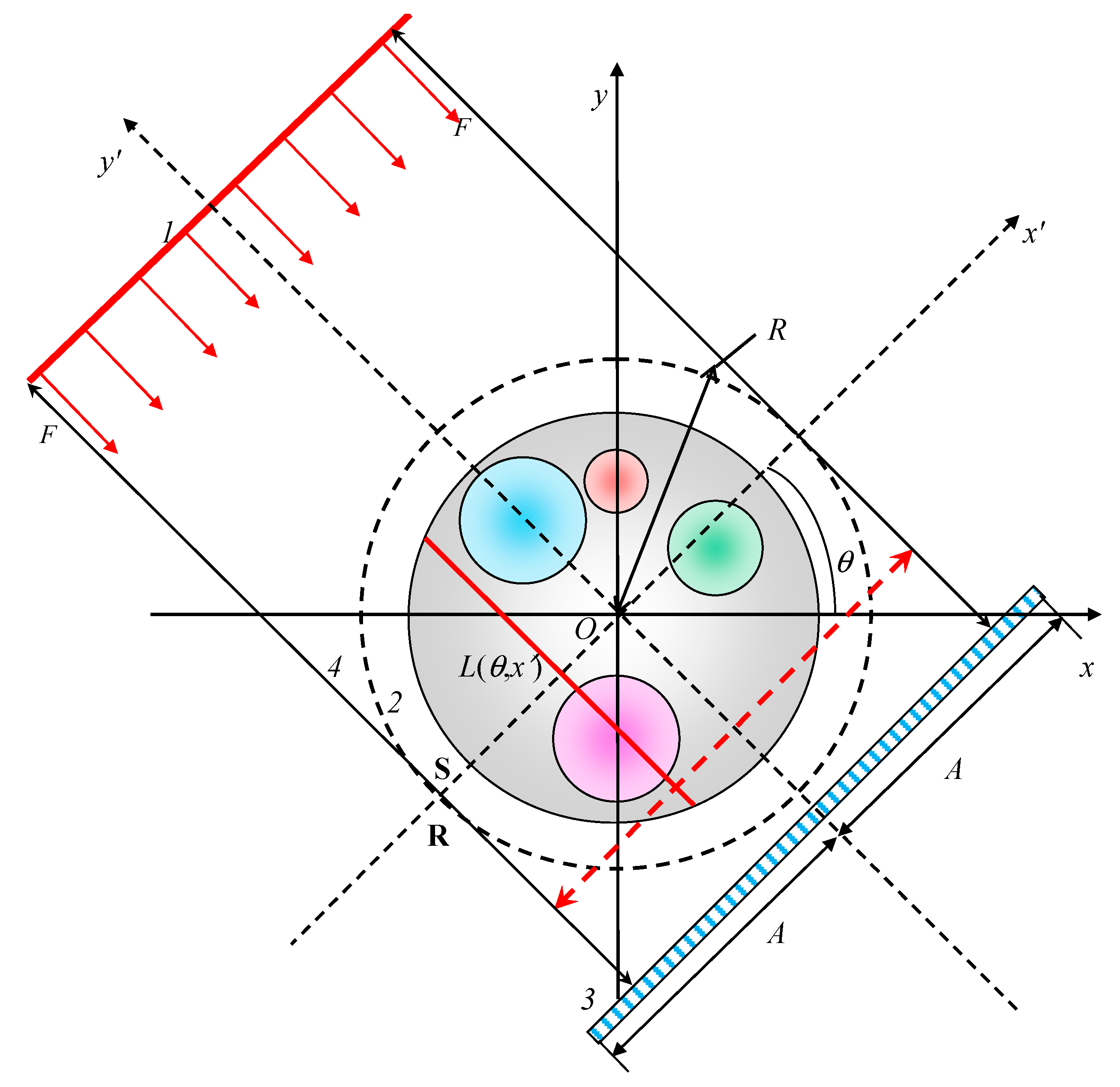
2.3. Method of Projection Formation in X-ray CT

The basis of the method for generating projections in X-ray CT is the model proposed in [14,37].
In accordance with the task under consideration, the TO contains one or more fragments, the materials of which may differ from the surrounding material by higher values of density and (or) effective atomic number.
Figure 1 shows a diagram of the formation of projections in the X-ray CT in the parallel beam geometry for the TO slice described by the set S2. Traditionally, fixed XOY and moving XOY′ Cartesian coordinate systems are used for the convenience of describing the process of projection formation. The finiteness of the set S allows it to be inscribed in a circle R2 with radius R. The coordinates of a point in the fixed coordinate system (x, y) are related to the coordinates of the same point in the moving coordinate system (x′, y′) by the rotation transformation by the angle θ [14,15]
x = x cos θ + y sin θ y = x sin θ + y cos θ ,     x = x cos θ y sin θ y = x sin θ + y cos θ .  
Angle θ characterizes one projection. The point with coordinates (x′, y′) belongs to the front surface of the detector’s array if |x′| ≤ A and y′ = F. Let the shadow of the TO slice S and the circumscribed circle R for any projection (0 ≤ θ ≤ 2π) does not go beyond the boundaries of the detector’s array, then R < A. The key element of the descriptive model of the process of generating projections in X-ray CT is the set of rays L (θ, x′) passing through the points x′, |x′| ≤ A, at an angle θ. The range and direction of the beam L (θ, x′) when generating the projection Pθ are indicated in Figure 1 red dotted arrow. The projection Pθ is understood as a set of integrals of the informative parameter over the entire set of rays L (θ, x′), |x′| ≤ A. The introduction lists the main informative parameters of X-ray CT and notes that density and effective atomic number are preferable for X-ray tomography as a means of measurement. This statement is obvious since it is these two parameters at fixed photon (gamma-ray) energy that uniquely determine the LAC of gamma radiation and all other informative parameters of the X-ray CT.
In accordance with the approach outlined in [14], we present an expression for estimating the TO thickness along the beam L (θ, x′) in mean free paths p ( E , x , θ ) for gamma radiation with energy E [14,15]
p ( E , x , θ ) = L ( θ , x ) m ( E , Z x , y ) ρ x , y d y .
The formula for calculating the estimate of radioscopic transparency T N * ( E max , x , θ ) along the beam L (θ, x′), taking into account expressions (9) for the counting registration mode, will take the form
T N * ( E max , x , θ ) = N 0 0 E max f N * ( E , E max , Z f , ρ f H f , Z d , ρ d H d ) exp p ( E , x , θ ) d E N 0 0 E max f N * ( E , E max , Z f , ρ f H f , Z d , ρ d H d ) d E .
For the integral registration mode, the expression T E * ( E max , x , θ ) for the estimate is derived from (10)–(12), taking into account (14), and looks similar to
T E * ( E max , x , θ ) = N 0 0 E max E a b ( p d , E ) f N * ( E , E max , Z f , ρ f H f , Z d , ρ d H d exp p ( E , x , θ ) d E Δ ADC N 0 f N * ( E , E max , Z f , ρ f H f , Z d , ρ d H d Δ ADC ,
The transformation of the distribution T ( E max , x , θ ) = T N * ( E max , x , θ ) T E * ( E max , x , θ ) into the projection Pθ, 0 ≤ θ ≤ 2π, has the form [14]
P θ = P ( E 0 , x , θ ) = ln T ( E max , x , θ )   R x R .
The complete set of projections P is equal to the union of unit projections (17) [14]
P = θ 0 , 2 π P θ .
The set of expressions (1)–(18) is a mathematical model of the generating projections in the X-ray CT for the counting and integral modes of registration of photon radiation. Moreover, radionuclides with a line energy spectrum, as well as X-ray machines, betatrons, and linear electron accelerators, can be used as a source of photons.

2.4. Method to Reconstruct the Slices

The projections generated in accordance with (1)–(18) are fed to the slice reconstruction code. This code is described in sufficient detail in [14]. We will follow the assumption that the presence of metal artifacts and their features in reconstructed images should not depend on which particular algorithm is used for reconstruction.
To restore images, we will use the back projection algorithm with filtering, which is described in [14] and implemented in our subroutine for Mathcad.

2.5. Metal Artifact Measure

To estimate the value of the metal artifact, we use the approach from [15]. This approach compares the reconstructed distributions of the LAC μ R ( x , y ) = m ( Z ( x , y ) ) ρ ( x , y ) R with some “ideal” distributions of the LAC μ i d ( x , y ) = m ( x , y ) ρ ( x , y ) i d .
Let us adapt the approach [15] to the considered artifact.
The measure of a metal artifact is the function m (x, y) [15]
Δ m ( x , y ) = μ R ( x , y ) μ i d ( x , y ) .
As an “ideal” distribution μ i d ( x , y ) , one can take the reconstructed LAC distribution from projections (17) obtained for theoretical radioscopic transparencies, (8)—for counting, and (9)—for integral registration modes. Such an interpretation μ i d ( x , y ) frees the researcher from the need to isolate metal artifacts from the result of the interaction between beam hardening artifacts and metal artifacts.

2.6. Specific Features of the Variation of the X-ray CT System Parameters

The goal of this research is to find ways to reduce metal artifacts by varying the parameters of the X-ray CT systems. The main variable parameters of X-ray CT systems are: the maximum energy of X-ray radiation Emax; the effective atomic number Zf and the mass thickness of the preliminary filter ρfhf; and the ADC bit depth kADC for the integral mode of registration.
It was noted above that reduction of metal artifact levels in X-ray CT is achieved by: increasing the maximum energy of X-ray radiation [7,11]; stiffening the X-ray beam due to its pre-filtering [9,10,11]; matching the variation ranges of the original analog and digital signals with respect to the integral mode of photon registration through the rational choice of ADC bit depth or narrowing the variation range of the primary analog signals [42].
Limitations associated with the choice of a pre-filter are associated with a decrease in the number of photons hitting the frontal detector surfaces, which leads to an increase in the effect of “photon (quantum) starvation” [11] and the necessity to increase the integration time.
In a number of cases, insufficient ADC bit depth causes the effect of “pseudo-quantum starvation” in digital radiography and X-ray CT [43] and leads to the appearance of metallic artifacts in the reconstructed images. The limitations associated with ADCs are due to the availability of fast ADCs with the required bit depth on the market for scientific equipment or preamplifiers that narrow the range of analog signals.
It is known that increasing the maximum energy Emax of X-rays leads to an increase in the energy Iab absorbed in the TO during the formation of projections. It is not the absolute value of absorbed energy that is of interest, but the degree of its increase kab in comparison with the base value of maximum energy Emax 0.
Regardless of the registration mode, the formula for estimating Iab (Emax) is as follows
I a b ( E max ) = N 0 E max 0 2 π R R 0 E max E f N * * ( E , E max ) L ( θ , x ) 0 y exp m ( E , Z x , y ) ρ x , y d y m a b E , Z x , y m E , Z x , y d y d E d θ d x ,
where m a b E , Z x , y is the mass absorption coefficient of photons with energy E at a point with coordinates x , y ; f N * * ( E , E max ) is the energy spectrum of a pre-filtered radiation source.
In accordance with the definition given above, the dependence of the degree of increase in absorbed energy kab when the maximum energy Emax changes is described by the expression
k a b ( E max , E max     0 ) = I a b ( E max ) / I a b ( E max     0 ) .
Evaluation of the kab parameter will judge the admissibility of increasing the maximum energy of X-rays in order to reduce metal artifacts in X-ray CT.

2.7. Summary

The combination of the above-improved model for the generation of projections in X-ray CT and the reconstruction algorithm from [14] is the basis for simulating metal artifacts in X-ray CT, as well as studying the effect of maximum photon radiation energies and ADC bit depth on the values of noted artifacts.

3. Modeling of Metal Artifacts in X-ray CT

It was noted above that metallic artifacts appear for TOs containing fragments of materials with a high density and large values of the effective atomic number, and the large sizes of the fragments, in this case, provide low radiation transparency. Simulation modeling will be carried out for the integral mode of photon registration.

3.1. Examples of Test Objects

Let us select four groups of objects for illustration. The first group includes TOs without cavities and with cavities, and the main material of TO is homogeneous in density. Representatives of the second group of objects contain fragments with a high density of their materials. The third group contains TOs with fragments with effective high atomic numbers of materials. The fourth group of objects includes fragments with properties from the second and third groups.

3.1.1. The Shape of Test Objects

We will consider objects with slices in the form of circles with and without round fragments to ensure high speed of calculations. It should be taken into account that the slices of the TO fragments meet the conditions (2). The expression to describe the slices Si, i = 1 … n, for the i-th fragment has the form
S i = ( x , y ) ,     x x 0     i 2 + y y 0     i 2 R i 2 ,       i = 2 n ,     n > 1 S 1 = ( x , y ) ,     x x 0     1 2 + y y 0     1 2 R 1 2 \ i = 2 n S i ,     n > 1
Here Ri is the radius of the i-th circle, and x0 i, y0 i are the coordinates of the center of the i-th circle.

3.1.2. Objects of the First Group

The first group includes objects without cavities and with cavities.
For an object without cavities, the set S1 (n = 1) corresponds to two sets ρ and Z
ρ = ρ ( x , y ) = ρ 1     ( x , y ) S 1 ,     Z = Z ( x , y ) = Z 1     ( x , y ) S 1 .
For an object with cavities, the sets ρ and Z (n ≥ 2) are described by the expressions
ρ = ρ ( x , y ) = ρ 1 ,     ( x , y ) S 1 0 ,         ( x , y ) i = 2 n S i ,     Z = Z ( x , y ) = Z 1 ,     ( x , y ) S 1 1 ,         ( x , y ) i = 2 n S i .
When modeling, the value of the effective atomic number of the material for the cavities does not matter in expression (24) since the density of the material in the cavities is zero.
There is no fundamental difference between the objects of this group for materials with different Z from the point of view of the analysis of metal artifacts.
Aluminum was chosen as the TO material of the first group. (Z = 13, ρ = 2.7 g/cm3).

3.1.3. Objects of the Second Group

It was noted above that representatives of the second group of objects contain fragments of materials with a high density.
For objects from this group, the sets ρ and Z (n ≥ 2) are represented as
ρ = ρ ( x , y ) = ρ 1 ,     ( x , y ) S 1 ρ i ,       ( x , y ) S i ,   i = 2 n ,     Z = Z ( x , y ) = Z 1 ,     ( x , y ) S 1 Z ,         ( x , y ) i = 2 n S i .
The Z value can be the same as Z1, density ρiρ1, and i = 2 … n.
Such objects have become widespread with the development of additive technologies in the production of materials.
Aluminum with a limiting density level was chosen as the TO material ρlim = 2.7 g/cm3. The density of fragments ρi varied in the range from 0 g/cm3 to ρlim.

3.1.4. Objects of the Third Group

The third group includes objects that are typical for the study of metal artifacts. Homogeneous and porous metal structures act as fragments of such objects.
In this case, the corresponding sets ρ and Z (n ≥ 2) are described by the formula
ρ = ρ ( x , y ) = ρ 1 ,     ( x , y ) S 1 ρ ,         ( x , y ) i = 2 n S i ,     Z = Z ( x , y ) = Z 1 ,     ( x , y ) S 1 Z i ,         ( x , y ) S i ,   i = 2 n .
Objects characterized by sets (26) were hypothetical until recently but have ceased to be so due to the development of additive technologies.
In the third group, the fixed parameter is the density, and you can use, for example, ρ = ρ1 = 2.25 g/cm3. Any set of effective atomic numbers can be used as the series Zi, taking into account the remark formulated above.

3.1.5. Objects of the Fourth Group

The fourth group is a generalization of the second and third groups.
The sets ρ and Z (n ≥ 2) for the fourth group can be represented by the expression
ρ = ρ ( x , y ) = ρ i ,     ( x , y ) S i ,   i = 1 n ,     Z = Z ( x , y ) = Z i ,     ( x , y ) S 1 ,   i = 1 n .
Arbitrary sets of materials can be used as examples of fragments characterized by parameters (Zi, ρi).

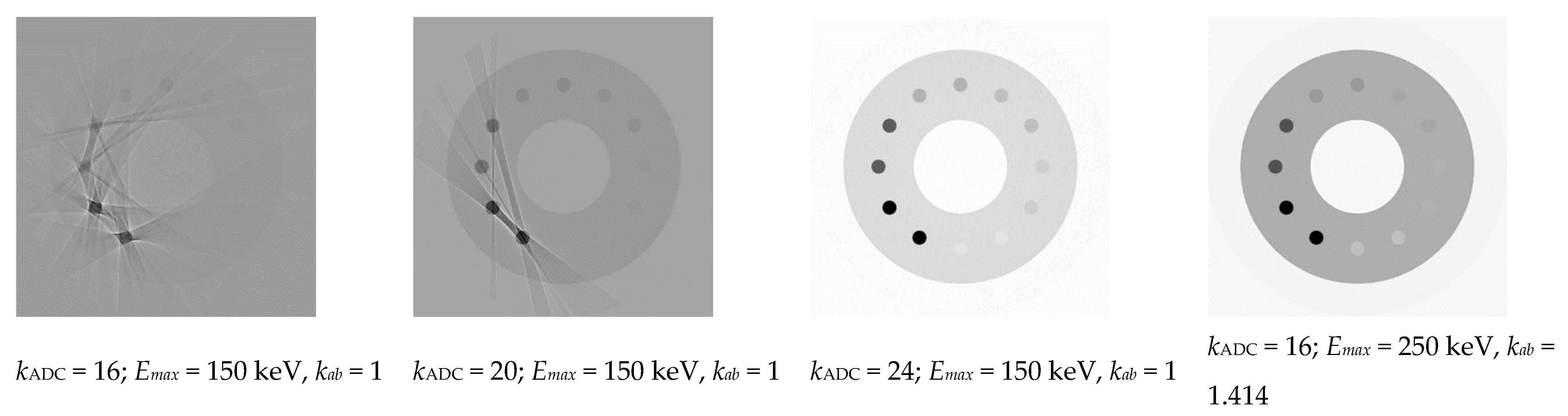
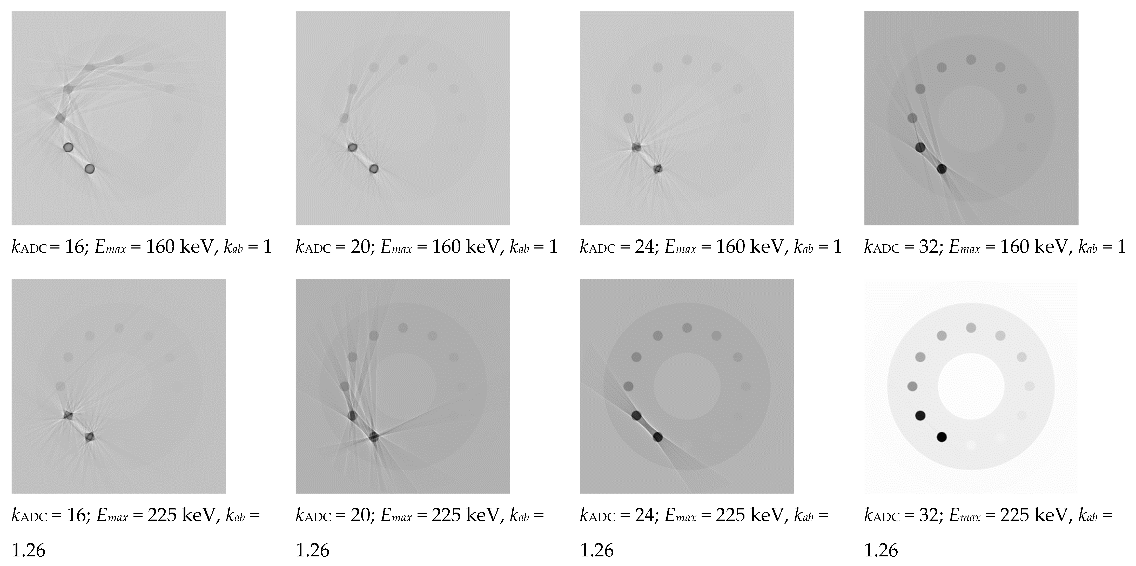
3.2. Results of Modeling Metal Artifacts

Kramers formula [44] with the minimum energy constraint in calculating the integrals was used to calculate the numerical energy spectrum of X-rays. The data from the gamma attenuation library [45] were used to generate the projections. The scintillator material was CdWO4 with a density ρd = 7.9 g/cm3. The thickness of the scintillator was 0.3 mm. The pre-filter material is copper (Zf = 29) with a density ρf = 8.9 g/cm3. ADC bit depth was kADC = 16. The parameter values were CADC = 1, 2, N0 = 108. The base level Emax = 150 keV is typical for many medical and industrial applications. The parameters of the X-ray CT system were varied as needed. For all examples, the number of samples in the projection was 640, the number of projections was 1800, and the pixel size was 0.4 mm. Computational experiments were performed for conditions of rigid collimation of X-rays and the same N0 level, independent of the Emax variation. The slice reconstruction was carried out by the inverse projection method with a Shepp-Logan filter [46].

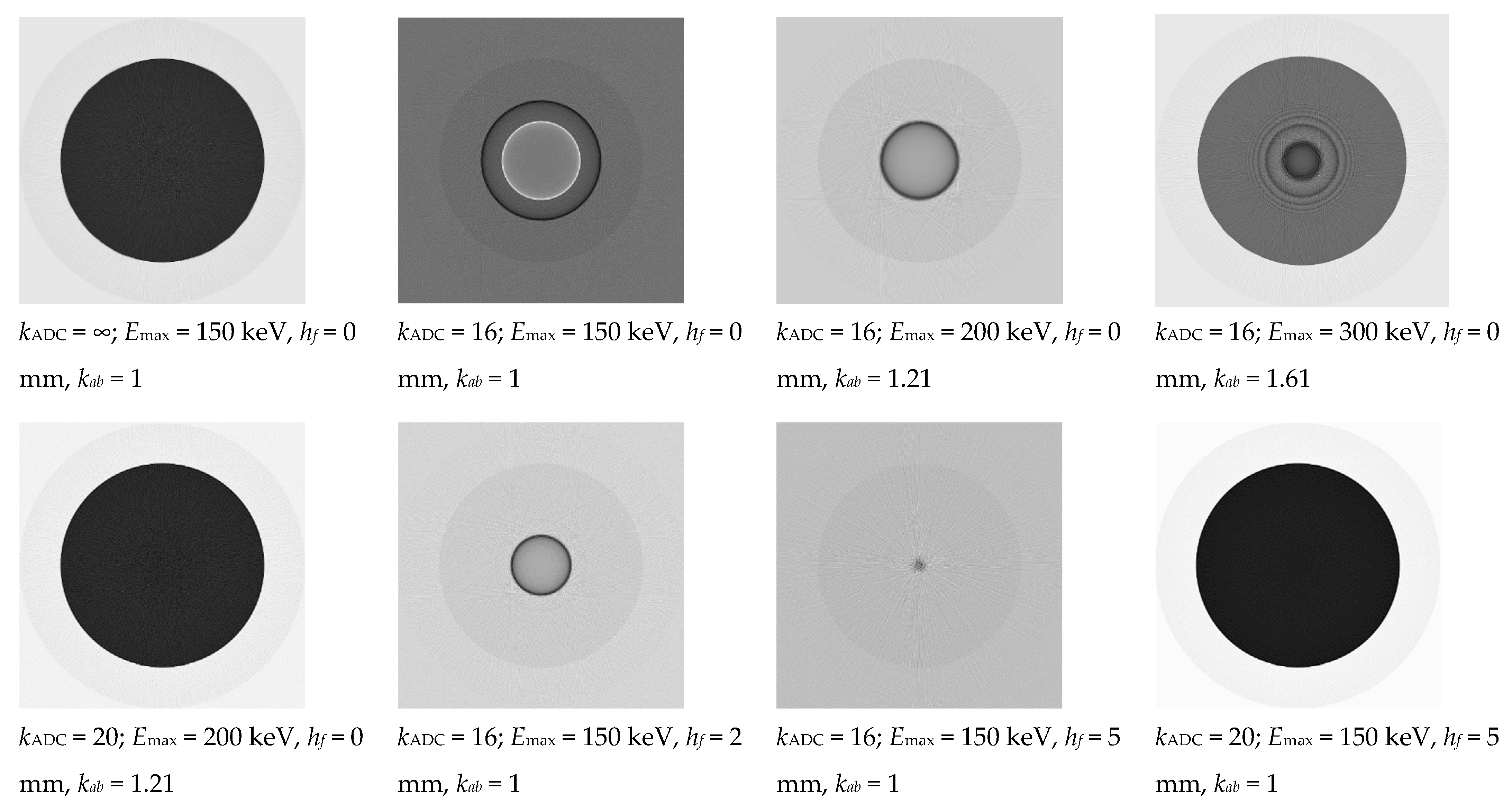
3.2.1. Objects of the First Group

The first group is represented by two objects: an aluminum cylinder with a diameter of 250 mm and an aluminum pipe with a diameter of 250 mm and a wall thickness of 75 mm.
Figure 2 shows reconstructed slices of a 250 mm diameter Al cylinder with variation in hf. kADC, Emax and hf.
From the above, we can conclude that there are practically no metal artifacts in the reconstructed slices for the object under consideration with the proper choice of the parameters of the X-ray CT system.
Figure 3 shows the results of the reconstructions for the above aluminum pipe, kADC = 16, and various parameter values, Emax and hf.
Image analysis (Figure 3) confirms the conclusion made above.

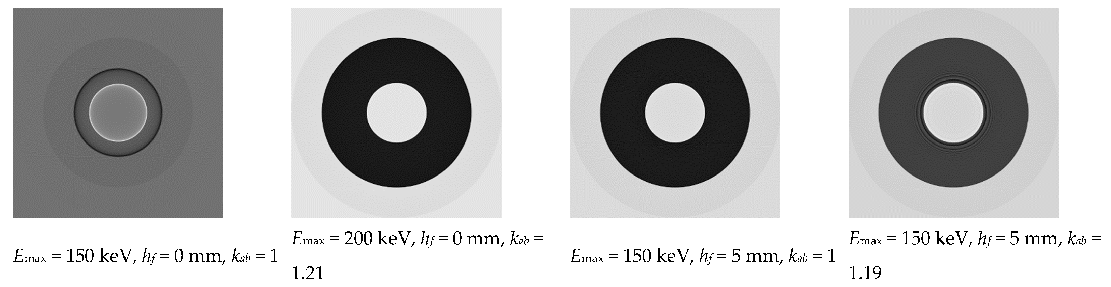
3.2.2. Objects of the Second Group

As an example, we chose an Al cylinder 250 mm in diameter with a central cylindrical cavity 100 mm in diameter and twelve cylindrical inserts 40 mm in diameter with densities from 0.2 g/cm3 to 2.4 g/cm3 in increments of 0.2 g/cm3.
Figure 4 shows the corresponding reconstructed slices.
For asymmetric objects, metallic artifacts appear as streaks [7,8,25,27,47,48]. For the simulated object and hf = 0 mm and kADC = 16, increasing the maximum energy to 300 keV leads to a decrease in streaks artifacts. The same effect for X-rays with Emax = 150 keV is achieved by increasing the ADC bit depth to kADC = 20 and using 5 mm thick copper pre-filters. Moreover, the simultaneous increase of the ADC bit depth and pre-filtering most effectively eliminate metal artifacts.
For the object under study, the correct choice of the parameters of the X-ray CT system made it possible to reduce the number of metal artifacts, as in the first two examples.

3.2.3. Objects of the Third Group

Objects of the third group are aluminum cylinders 200 mm in diameter with a central cylindrical cavity 80 mm in diameter with local inclusions in the form of cylinders from the materials listed in Table 1. The diameters of local inclusions are 12 mm. For objects of the third group, materials are hypothetical foams with a density ρ = 2 g/cm3.
Modeling was performed without pre-filtering, taking into account the recommendations [14] for the maximum energy of X-ray radiation Emax = 150 keV and for three levels of ADC bit depth kADC = 16; 20; 24, and for the maximum energy of X-ray radiation, Emax = 250 keV and ADC bit depth kADC = 16.
Figure 5 shows reconstructed slices of the test object.
For the class of objects under consideration, an even more pronounced manifestation of metal artifacts in the form of streaks is observed [7,8,25,27,47,48]. From the analysis of the images presented in Figure 5, we can conclude that the goal of correcting metal artifacts is achieved in two ways: by increasing the ADC bit depth to kADC = 24 for Emax = 150 keV or by achieving the maximum energy Eeff = 250 keV for ADC bit depth kADC = 16.

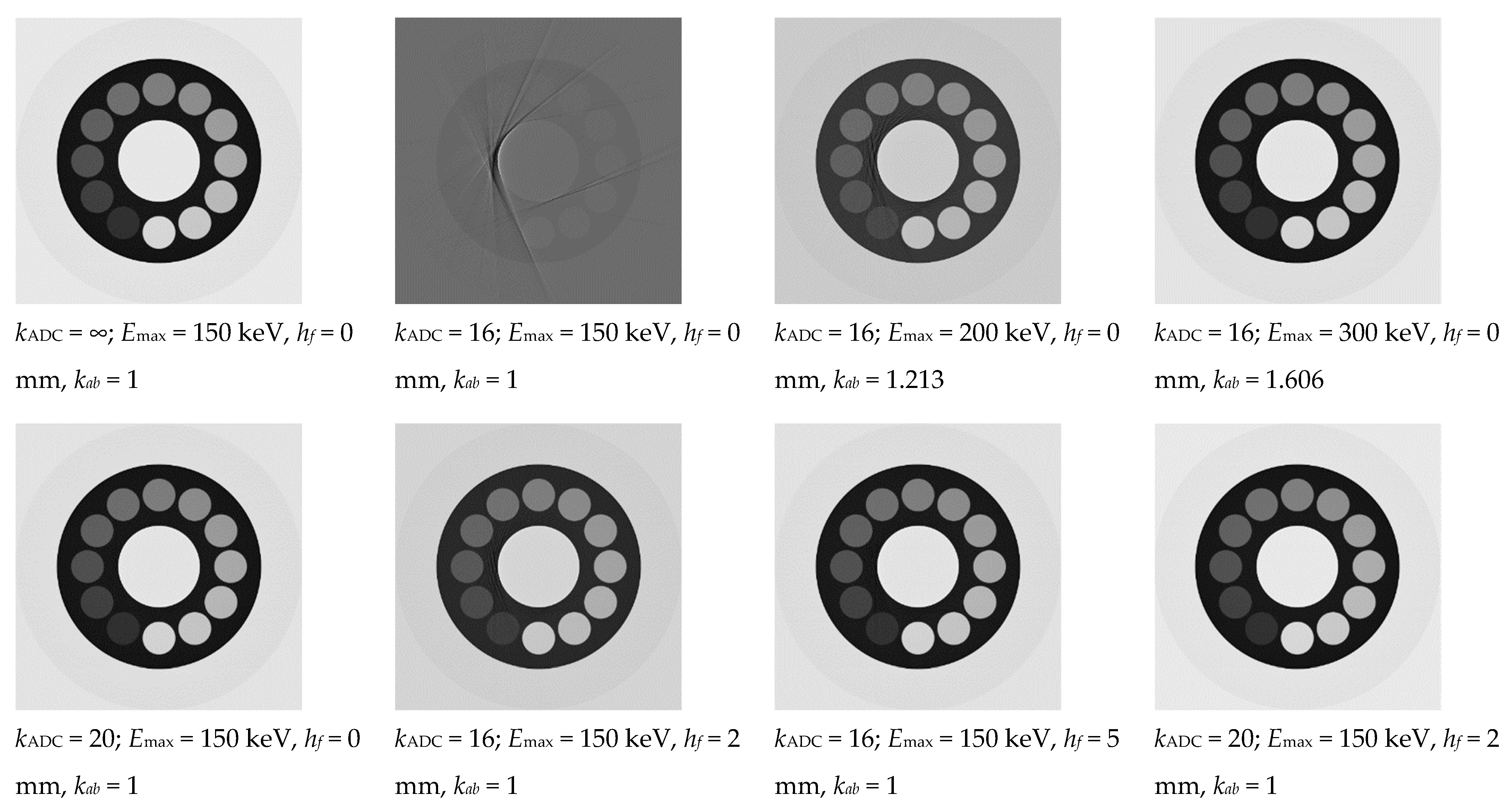
3.2.4. Objects of the Fourth Group

The objects of the fourth group differ from the third group in the density of materials of local inclusions (see Table 1).
In the objects of the analyzed group, the range of changes, not only in the atomic numbers of fragment materials but also in their densities, has increased. Simulation modeling was performed for Emax = 160 keV and Emax = 225 keV.
Figure 6 shows the simulation results for hf = 0.
From the analysis of the data shown in Figure 6, we can conclude that the significant reduction in the level of metallic artifacts by increasing the ADC bit depth for Emax = 160 keV is practically unrealizable. The necessary effect is achieved by simultaneously increasing the maximum X-ray energy to 225 keV and the ADC bit depth kADC = 24, kADC = 32. An increase in Emax from 160 keV to 225 keV results in a 26% increase in the absorbed energy in the TO.

4. Discussion

4.1. General Statements

The developed mathematical model and the code for its implementation make it possible to simulate metal artifacts and reduce their magnitude by varying the maximum X-ray energy, the thickness, the material of the pre-filter, and the ADC bit depth.
It should be noted that an increase in the ADC bit depth and pre-filter thickness is effective in the case of a sufficient number of N0 photons recorded by the detector behind the test object. The specific level N0 depends not only on the general parameters of the TO and the CT system but also on the number of projections.
The title of the article contains a question about the nature of the metal artifact. This question is not idle for two reasons. The first refers to the expansion of the range of problems solved using various implementations of X-ray CT, with a simultaneous increase in the range of test objects in size range (from micro to macro) and the complication of their structure with the inclusion of high-density fragments, including those from heavy metals. Researchers interested in using X-ray CT for solving their specific problems have an easily justified temptation to use existing standard X-ray CT systems; as a rule, these are medical tomographs. The discrepancy between the low levels of radioscopic transparency of research objects and the parameters of the selected systems leads to pronounced metal artifacts. The second reason is no less important and is associated with the rapid development of algorithmic approaches to the compensation of metal artifacts [2,18,25,26,27,49,50,51]. Algorithmic approaches implicitly and explicitly assume the presence of information about the X-ray opaque areas of the test objects.
It follows from the law of attenuation of gamma radiation that for an object of any size with an arbitrary density and an arbitrary value of the effective atomic number of the material, the probability of a photon passing without attenuation is finite. From this follows the fundamental physical feasibility of the task of monitoring objects by the methods of DR and X-ray CT. The technical feasibility of the inspection task is understood as the availability of technical means that allow inspecting at a given time with the required quality with a set of restrictions specified by the consumer.
The following proposition is theoretically substantiated and illustrated by the results of the computational experiment in Section 1 and Section 2. The radioscopic transparency of objects in combination with the radiometric detector loading, the maximum energy of X-ray radiation, the ADC bit depth for the integral photon detection mode, and the thickness of the pre-filter determine the presence or absence of metal artifacts in the reconstructed TO slices. From the foregoing, it follows that the presence of metal artifacts is associated with the technical feasibility of the inspection task by the X-ray CT method. The answer to the question posed in the article title is formulated as follows: metal artifacts are of a technical nature due to the incorrect choice of the parameters of the X-ray CT systems, which determines the actual and physical laws of attenuation and registration of X-rays for specific objects.
Such an answer should be an incentive for designers and developers when choosing the parameters of X-ray CT systems based on the inadmissibility of metal artifacts for specific test objects for which specialized X-ray CT systems are designed.

4.2. Comparison of Simulation Results with Known Ones

A visual comparison of the results of modeling metal artifacts in X-ray CT with the data of other authors [7,8,25,27,47,48] showed their closeness for similar phantoms.
We also note the confirmation of the main statements cited above.
Works [11,18,47,52] note the effect of “photon starvation,” that is, a low level of the product of radioscopic transparency and the number of initial photons, which leads to the appearance of metallic artifacts. Images from [47] illustrate the conclusion that a decrease in radioscopic transparency is associated with an increase in the significance of metal artifacts. Works [7,49,53] emphasize the importance of choosing the energy of the X-ray source and filtering the beam to exclude metallic artifacts. Metal artifacts significantly complicate the interpretation of the final images in other implementations of computed tomography [54,55,56,57].
Based on a visual comparison of images of ideal and real distributions of the linear X-ray attenuation coefficient over the cross sections of test samples, we proved that for the integral photon detection mode, the reduction of metal artifacts in X-ray computed tomography is achieved by increasing the intensity of the X-ray source, increasing its maximum energy, and increasing the ADC bit depth. The development of criteria for the rational choice of the noted parameters is beyond the scope of this article; however, in the context of the discussion, we will propose several ideas for future research.

4.3. On the Rational Choice of Parameters of X-ray Computed Tomography

The objects of control in the problem under consideration are characterized by low radioscopic transparency, at least for one of the angles.
Let us consider several ideas regarding the choice of parameters of the X-ray computed tomography system from the condition of minimizing the influence of the analyzed factor on the quality of the reconstructed images of the sections of the test object. The analyzed factor is the level of radioscopic transparency, which, when it decreases, leads to the appearance of metal artifacts on the final tomographic images. These metallic artifacts appear on the images in the form of several divergent bands for single, almost opaque local fragments and form a stellate structure for a complex of such local fragments (see Figure 4, Figure 5 and Figure 6). These stripe or stellate structures are transformed as the radioscopic transparency of objects increases as a result of changes in the parameters of the X-ray computed tomography system.
It was noted above that, in the last decade, there has been a tendency for computed tomography to transform from a means of visualizing the internal structure of objects into a means of measurement. In this situation, it is especially necessary to develop a criterion for choosing X-ray computed tomography parameters in order to reduce metal artifacts.
The main interest of research is related to metal artifacts, so we will correct the metal artifact measure (19) by changing the interpretation of the concept of “ideal” distribution. In the problem we are considering, taking into account the trends noted above, it is logical to consider a pointwise criterion for the closeness of real μ R ( x , y ) and “ideal” μ i d * ( x , y ) linear attenuation coefficients. Here, the μ i d * ( x , y ) reconstructed distribution of linear attenuation coefficients from projections (17) obtained for theoretically calculated radioscopic transparencies (15)—for counting and (16)—for integral registration modes is taken as. The specified transparencies are calculated for the same values of maximum energy E max ; for the “ideal” linear attenuation coefficient, calculations are carried out for k ADC and N 0 .
Let Q be a set of triples q = N 0 , E max , k ADC , and then as a criterion for the rational choice of X-ray computed tomography parameters, we can propose a solution to the following inequality
max x , y R μ R ( x , y , q ) μ i d * ( x , y , q 0 ) Δ lim ,
Here q 0 = , E max , ; Δ lim —given the level of deviation error of linear attenuation coefficients.
The solution of inequality (28) will be some subset Q 0 , Q 0 Q . The specific choice of the required triplet of parameters is carried out by the developer of X-ray CT based on the market of scientific equipment. In this case, it is necessary to take into account the admissibility of the degree of increase in the absorbed energy kab.

5. Conclusions

An adaptation of a simulation model for evaluating metal artifacts in X-ray computed tomography in a parallel beam geometry is proposed. The simulation model was transformed into a MathCad program designed to simulate images of the internal structure of the tested objects. The efficiency of the metal artifacts simulation algorithm is demonstrated in the example of symmetric and asymmetric objects with low- and high-density inclusions and inclusions from materials with high values of effective atomic number. The possibility of correcting the analyzed artifacts is demonstrated on the basis of the analysis of the results of numerical experiments carried out in order to rationally choose the maximum energy and bit depth of the ADC. The results of the research can be used at the design stage of X-ray computed tomography systems designed to control objects with fragments of low radiation transparency.

Author Contributions

Methodology, S.P.O., D.A.S., O.S.O. and E.Y.U.; Software, S.V.C., V.Y.Z. and E.Y.U.; Formal analysis, D.A.S.; Writing—original draft, S.P.O., S.V.C. and O.S.O.; Writing—review & editing, V.Y.Z.; Project administration, S.P.O. All authors have read and agreed to the published version of the manuscript.

Funding

The study has been performed under the financial support by the Ministry of Science and Higher Education of the Russian Federation within the state task “Research” (basic fundamental), project # FSWW-2023-0004.

Institutional Review Board Statement

Not applicable.

Informed Consent Statement

Not applicable.

Data Availability Statement

Not applicable.

Conflicts of Interest

The authors declare no conflict of interest.

References

  1. Hsieh, J. Computed Tomography: Principles, Design, Artifacts, and Recent Advances; SPIE: Bellingham, WA, USA, 2015. [Google Scholar]
  2. Zhu, L.; Han, Y.; Li, L.; Xi, X.; Zhu, M.; Yan, B. Metal artifact reduction for x-ray computed tomography using U-net in image domain. IEEE Access. 2019, 7, 98743–98754. [Google Scholar] [CrossRef]
  3. Sarkar, S.; Wahi, P.; Munshi, P. An empirical correction method for beam-hardening artifact in Computerized Tomography (CT) images. NDT E Int. 2019, 102, 104–113. [Google Scholar] [CrossRef]
  4. Dremel, K.; Fuchs, T. Scatter simulation and correction in computed tomography: A reconstruction-integrated approach modeling the forward projection. NDT E Int. 2017, 86, 132–139. [Google Scholar] [CrossRef]
  5. Stolfi, A.; De Chiffre, L.; Kasperl, S. Error Sources. In Industrial X-ray Computed Tomography; Springer: Berlin, Germany, 2018; pp. 143–184. [Google Scholar] [CrossRef] [Green Version]
  6. Villarraga-Gómez, H.; Herazo, E.L.; Smith., S.T. X-ray computed tomography: From medical imaging to dimensional metrology. Precis. Eng. 2019, 60, 544–569. [Google Scholar] [CrossRef]
  7. Boas, F.E.; Fleischmann, D. CT artifacts: Causes and reduction techniques. Imaging Med. 2012, 4, 229–240. Available online: http://www.edboas.com/science/CT/0012.pdf (accessed on 12 February 2023). [CrossRef] [Green Version]
  8. Hur, J.; Kim, D.; Shin, Y.G.; Lee, H. Metal artifact reduction method based on a constrained beam-hardening estimator for polychromatic x-ray CT. Phys. Med. Biol. 2021, 66, 065025. [Google Scholar] [CrossRef]
  9. Kuchenbecker, S.; Faby, S.; Sawal, S.; Lell, M.; Kachelrieß, M. Dual energy CT: How well can pseudo-monochromatic imaging reduce metal artifacts? Med. Phys. 2015, 42, 1023–1036. [Google Scholar] [CrossRef] [PubMed]
  10. Herl, G.; Hiller, J.; Sauer, T. Artifact Reduction in X-Ray Computed Tomography by Multi-Positional Data Fusion Using Local Image Quality Measures. In Proceedings of the 9th Conference on Industrial Computed Tomography (iCT 2019), Padova, Italy, 13–15 February 2019; Available online: https://www.ndt.net/article/ctc2019/papers/iCT2019_Full_paper_5.pdf (accessed on 12 February 2023).
  11. Katsura, M.; Sato, J.; Akahane, M.; Kunimatsu, A.; Abe, O. Current and novel techniques for metal artifact reduction at CT: Practical guide for radiologists. Radiographics 2018, 38, 450–461. [Google Scholar] [CrossRef] [Green Version]
  12. Villarraga-Gómez, H.; Lee, C.B.; Smith, S.T. Dimensional metrology with X-ray CT: A comparison with CMM measurements on internal features and compliant structures. Precis. Eng. 2018, 51, 291–307. [Google Scholar] [CrossRef]
  13. Ferrucci, M.; Ametova, E. Charting the course towards dimensional measurement traceability by x-ray computed tomography. Meas. Sci. Technol. 2021, 32, 092001. [Google Scholar] [CrossRef]
  14. Osipov, S.P.; Yadrenkin, I.G.; Chakhlov, S.V.; Osipov, O.S.; Usachev, E.Y.; Manushkin, A.A. Calculation model of X-ray computed tomography with density assessment function. Russ. J. Nondestruct. Test. 2021, 57, 222–237. [Google Scholar] [CrossRef]
  15. Osipov, S.P.; Mirzoev, K.D.; Chakhlov, S.V.; Osipov, O.S.; Usachev, E.Y. Simulation model for evaluation of non-monoenergeticity and scattering artifacts in computer tomography. Russ. J. Nondestruct. Test. 2021, 57, 579–594. [Google Scholar] [CrossRef]
  16. Schwab, J. Deep Learning Methods for Limited Data Problems in X-Ray Tomography. In Handbook of Mathematical Models and Algorithms in Computer Vision and Imaging: Mathematical Imaging and Vision; Chen, K., Schönlieb, C.B., Tai, X.C., Younces, L., Eds.; Springer International Publishing: Cham, Switzerland, 2022; pp. 1–20. [Google Scholar] [CrossRef]
  17. Park, H.S.; Jung, J.; Seo, J.K. Pseudo-monochromatic Imaging in Industrial X-Ray Computed Tomography. SIAM J. Imaging Sci. 2021, 14, 1306–1325. [Google Scholar] [CrossRef]
  18. Hegazy, M.A.A.; Cho, M.H.; Cho, M.H.; Lee, S.Y. Metal Artifact Reduction in Dental CBCT Images Using Direct Sinogram Correction Combined with Metal Path-Length Weighting. Sensors 2023, 23, 1288. [Google Scholar] [CrossRef] [PubMed]
  19. Hermanek, P.; Rathore, J.S.; Aloisi, V.; Carmignato, S. Principles of X-ray Computed Tomography. In Industrial X-ray Computed Tomography; Carmignato, S., Dewulf, W., Leach, R., Eds.; Springer: Cham, Switzerland, 2018; pp. 25–67. [Google Scholar] [CrossRef]
  20. Zhang, H.M.; Dong, B. A Review on Deep Learning in Medical Image Reconstruction. J. Oper. Res. Soc. China 2020, 8, 311–340. [Google Scholar] [CrossRef] [Green Version]
  21. Solovev, D.B.; Kuzora, S.S. Modeling the Assessment of Readiness of a Territorial Entity of the Russian Federation for Innovation Activities (on the Example of Primorsky Krai). In Proceeding of the International Science and Technology Conference “FarEastCon 2020”. Smart Innovation, Systems and Technologies; Solovev, D.B., Savaley, V.V., Bekker, A.T., Petukhov, V.I., Eds.; Springer: Singapore, 2021; Volume 227, pp. 13–26. [Google Scholar] [CrossRef]
  22. Johnson, W.L.; Benzing, J.T.; Kafka, O.L.; Moser, N.H.; Harris, D.; Iten, J.; Hrabe, N.W. Sensitivity of acoustic nonlinearity and loss to residual porosity in additively manufactured aluminum. NDT E Int. 2023, 135, 102801. [Google Scholar] [CrossRef]
  23. Boichuk, A.S.; Dikov, I.A.; Chertishchev, V.Y.; Generalov, A.S. Determining Porosity of Monolithic Zones in Aircraft Parts and Assemblies Made of PCMs Using Ultrasound Pulse Echo Method. Russ. J. Nondestruct. Test. 2019, 55, 1–7. [Google Scholar] [CrossRef]
  24. Rodriguez-Sotelo, D.; Rodriguez-Licea, M.A.; Araujo-Vargas, I.; Prado-Olivarez, J.; Barranco-Gutiérrez, A.-I.; Perez-Pinal, F.J. Power Losses Models for Magnetic Cores: A Review. Micromachines 2022, 13, 418. [Google Scholar] [CrossRef]
  25. De Man, B.; Nuyts, J.; Dupont, P.; Marchal, G.; Suetens, P. Reduction of metal streak artifacts in x-ray computed tomography using a transmission maximum a posteriori algorithm. IEEE Trans. Nucl. Sci. 2000, 47, 977–981. [Google Scholar] [CrossRef] [Green Version]
  26. Zhang, Y.; Yu, H. Convolutional neural network based metal artifact reduction in x-ray computed tomography. IEEE Trans. Med. Imaging 2018, 37, 1370–1381. [Google Scholar] [CrossRef]
  27. Amirkhanov, A.; Heinzl, C.; Reiter, M.; Kastner, J.; Groller, E. Projection-based metal-artifact reduction for industrial 3D X-ray computed tomography. IEEE Trans. Vis. Comput. Graph. 2011, 17, 2193–2202. [Google Scholar] [CrossRef] [Green Version]
  28. Kunz, A.S.; Patzer, T.S.; Grunz, J.P.; Luetkens, K.S.; Hartung, V.; Hendel, R.; Fiber, T.; Genest, F.; Ergün, S.; Bley, T.A.; et al. Metal artifact reduction in ultra-high-resolution cone-beam CT imaging with a twin robotic X-ray system. Sci. Rep. 2022, 12, 1–11. [Google Scholar] [CrossRef]
  29. Osipov, S.; Chakhlov, S.; Shan, J.; Kairalapov, D. Analysis of the possibility of determining the internal structure of oil and gas pipes by CT method. Mater. Sci. Forum 2019, 970, 187–201. [Google Scholar] [CrossRef]
  30. Rassner, U. Pearls and pitfalls of spine imaging. Radiol. Clin. N. Am. 2018, 57, 233–255. [Google Scholar] [CrossRef]
  31. Jumanazarov, D.; Koo, J.; Busi, M.; Poulsen, H.F.; Olsen, U.L.; Iovea, M. System-independent material classification through X-ray attenuation decomposition from spectral X-ray CT. NDT E Int. 2020, 116, 102336. [Google Scholar] [CrossRef]
  32. Withers, P.J.; Bouman, C.; Carmignato, S.; Cnudde, V.; Grimaldi, D.; Hagen, C.K.; Maire, E.M.; Manley, M.; Du Plessis, A.; Stock, S.R. X-ray computed tomography. Nat. Rev. Methods Prim. 2021, 1, 18. [Google Scholar] [CrossRef]
  33. Lim, C.H.; Lee, J.; Choi, Y.; Park, J.W.; Kim, H.K. Advanced container inspection system based on dual-angle X-ray imaging method. J. Instrum. 2021, 16, P08037. [Google Scholar] [CrossRef]
  34. Yokhana, V.S.K.; Arhatari, B.D.; Abbey, B. Materials Separation via the Matrix Method Employing Energy-Discriminating X-ray Detection. Appl. Sci. 2022, 12, 3198. [Google Scholar] [CrossRef]
  35. Günther, B.; Gradl, R.; Jud, C.; Eggl, E.; Huang, J.; Kulpe, S.; Achterhold, K.; Gleich, B.; Dierolf, M.; Pfeiffer, F. The versatile X-ray beamline of the Munich Compact Light Source: Design, instrumentation and applications. J. Synchrotron. Rad. 2020, 27, 1395–1414. [Google Scholar] [CrossRef]
  36. Detection Technology. X-ACE Medical CT Detector. Available online: https://www.deetee.com/product/x-ace-32/ (accessed on 12 February 2023).
  37. Osipov, S.P.; Yadrenkin, I.G.; Chakhlov, S.V.; Osipov, O.S.; Usachev, E.Y. Simulation modeling in digital radiography with allowance for spatial outlines of test objects. Russ. J. Nondestruct. 2020, 56, 647–660. [Google Scholar] [CrossRef]
  38. Osipov, S.P.; Prischepa, I.A.; Chakhlov, S.V.; Osipov, O.S.; Usachev, E.Y. Algorithms for modeling the formation and processing of information in X-ray tomography of foam materials. Russ. J. Nondestruct. Test. 2021, 57, 238–250. [Google Scholar] [CrossRef]
  39. Li, L.; Li, R.; Zhang, S.; Zhao, T.; Chen, Z. A dynamic material discrimination algorithm for dual MV energy X-ray digital radiography. Applied Rad. Isot. 2016, 114, 188–195. [Google Scholar] [CrossRef]
  40. Osipov, S.P.; Usachev, E.J.; Chakhlov, S.V.; Schetinkin, S.A.; Osipov, O.S. Inspection of bulk cargoes and liquids by the dual energy method. Radiat. Phys. Chem. 2020, 177, 109133. [Google Scholar] [CrossRef]
  41. Ghaebi, M.; Tajik, M.; Azimirad, R. Studying the effect of the scanned objects’ location on material discrimination in a dual-energy cargo inspection system. Nucl. Instrum. Methods Phys. Res. B Beam Interact. Mater. At. 2022, 510, 39–48. [Google Scholar] [CrossRef]
  42. Shi, L.; Berger, M.; Bier, B.; Soell, C.; Roeber, J.; Fahrig, R.; Eskofier, B.; Maier, A.; Maier, J. Analog non-linear transformation-based tone mapping for image enhancement in C-arm CT. In Proceedings of the 2016 IEEE Nuclear Science Symposium, Medical Imaging Conference and Room-Temperature Semiconductor Detector Workshop (NSS/MIC/RTSD), Strasbourg, France, 29 October–6 November 2016; pp. 1–3. [Google Scholar] [CrossRef]
  43. Zhvyrblia, V.Y.; Osipov, S.P.; Sednev, D.A. Increasing penetrating power of digital radiography systems based on analysis of low-intensity signals. Russ. J. Nondestruct. Test. 2022, 58, 583–597. [Google Scholar] [CrossRef]
  44. Kramers, H.A. XCIII. On the theory of X-ray absorption and of the continuous X-ray spectrum. Phil. Mag. 1923, 46, 836–871. [Google Scholar] [CrossRef]
  45. Berger, M.J.; Hubbell, J.H.; Seltzer, S.M.; Chang, J.; Coursey, J.S.; Sukumar, R.; Zucker, D.S.; Olsen, K. XCOM: Photon Cross Sections Database, NIST Standard Reference Database 8 (XGAM). Available online: https://www.nist.gov/pml/xcom-photon-cross-sections-database (accessed on 12 February 2023). [CrossRef]
  46. Shepp, L.A.; Logan, B.F. The Fourier reconstruction of a head section. IEEE Trans. Nucl. Sci. 1974, 21, 21–43. [Google Scholar] [CrossRef]
  47. Pettersson, E.; Bäck, A.; Björk-Eriksson, T.; Lindencrona, U.; Petruson, K.; Thilander-Klang, A. Structure delineation in the presence of metal—A comparative phantom study using single and dual-energy computed tomography with and without metal artefact reduction. Phys. Imaging Radiat. Oncol. 2019, 9, 43–49. [Google Scholar] [CrossRef] [Green Version]
  48. Park, H.S.; Choi, J.K.; Seo, J.K. Characterization of metal artifacts in X-ray computed tomography. Commun. Pure Appl. Math. 2017, 70, 2191–2217. [Google Scholar] [CrossRef] [Green Version]
  49. Jumanazarov, D.; Koo, J.; Kehres, J.; Poulsen, H.F.; Olsen, U.L.; Iovea, M. Material classification from sparse spectral X-ray CT using vectorial total variation based on L infinity norm. Mater. Charact. 2022, 187, 111864. [Google Scholar] [CrossRef]
  50. Hashem, N.; Pryor, M.; Haas, D.; Hunter, J. Design of a Computed Tomography Automation Architecture. Appl. Sci. 2021, 11, 2858. [Google Scholar] [CrossRef]
  51. Busi, M.; Kehl, C.; Frisvad, J.R.; Olsen, U.L. Metal Artifact Reduction in Spectral X-ray CT Using Spectral Deep Learning. J. Imaging 2022, 8, 77. [Google Scholar] [CrossRef] [PubMed]
  52. Hai, C.; He, J.; Li, B.; He, P.; Sun, L.; Wu, Y.; Yang, M. Dual-domain metal trace inpainting network for metal artifact reduction in baggage CT images. Measurement 2023, 207, 112420. [Google Scholar] [CrossRef]
  53. Richtsmeier, D.; O’Connell, J.; Rodesch, P.A.; Iniewski, K.; Bazalova-Carter, M. Metal artifact correction in photon-counting detector computed tomography: Metal trace replacement using high-energy data. Med. Phys. 2023, 50, 380–396. [Google Scholar] [CrossRef] [PubMed]
  54. Mellander, H.; Fransson, V.; Ydström, K.; Lätt, J.; Ullberg, T.; Wassélius, J.; Ramgren, B. Metal artifact reduction by virtual monoenergetic reconstructions from spectral brain CT. Eur. J. Radiol. Open 2023, 10, 100479. [Google Scholar] [CrossRef]
  55. Borges, A.P.; Antunes, C.; Curvo-Semedo, L. Pros and Cons of Dual-Energy CT Systems: “One Does Not Fit All”. Tomography 2023, 9, 195–216. [Google Scholar] [CrossRef]
  56. Taguchi, K.; Iwanczyk, J.S. Vision 20/20: Single photon counting x-ray detectors in medical imaging. Med. Phys. 2013, 40, 100901. [Google Scholar] [CrossRef] [Green Version]
  57. Glinz, J.; Zabler, S.; Kastner, J.; Senck, S. Metal artifacts in attenuation and phase contrast X-ray microcomputed tomography: A comparative study. Exp. Mech. 2022, 62, 837–847. [Google Scholar] [CrossRef]
Figure 1. Scheme of projection formation in X-ray CT in parallel beam geometry: 1—photon radiation source; 2—test object; 3—detector array; 4—a circle describing the test object section.
Applsci 13 02666 g001
Figure 2. Reconstructed slices of an aluminum cylinder with a diameter of 250 mm.
Applsci 13 02666 g002
Figure 3. Reconstructed slices of an aluminum pipe with a diameter of 250 mm and a wall thickness of 75 mm, kADC = 16.
Applsci 13 02666 g003
Figure 4. Reconstructed slices of a 250 mm aluminum cylinder with cylindrical inserts.
Applsci 13 02666 g004
Figure 5. Reconstructed slices of an aluminum cylinder 200 mm in diameter with cylindrical inserts (Table 1, group 3).
Applsci 13 02666 g005
Figure 6. Reconstructed slices of an aluminum cylinder 200 mm in diameter with cylindrical inserts (Table 1, group 4).
Applsci 13 02666 g006
Table 1. Atomic numbers and material densities of test object fragments.
GroupZ131323232626292940404747
3ρ, g/cm3222222222222
4ρ, g/cm31.5234567856910
Disclaimer/Publisher’s Note: The statements, opinions and data contained in all publications are solely those of the individual author(s) and contributor(s) and not of MDPI and/or the editor(s). MDPI and/or the editor(s) disclaim responsibility for any injury to people or property resulting from any ideas, methods, instructions or products referred to in the content.

