1. Introduction
Evacuation refers to a temporary but rapid relocation of people, individually or in an organized manner, from a threatened or disaster area to a safe place as a rescue or precautionary measure [
1]. In comparison with any other kind of evacuation, ship evacuation in an emergency is vital in the occurrence of an accident on the vessel and presents a number of differences in several aspects. It can be described as a process that follows the decision of the commanding officer to abandon the ship for the safety of the passengers and crew and is the last resort in case of emergency.
In the case of a critical incident onboard that requires mustering, evacuation and abandonment of the ship, an evacuation alarm is sounded through the PA system and the crew organizes the orderly assembly of passengers to the muster stations. Once the decision for ship abandonment has been taken, the crew organizes the transfer of passengers to the embarkation stations and prepares the LSAs and survival crafts for embarkation and launching. In this process, crew members follow the established procedures and guidelines, providing instructions to passengers and facilitating their movement to the designated stations, as described in the MSC/Circ. 699 Revised Guidelines for passenger safety instructions [
2].
The capacity and the size of large passenger ships has increased in the last decade, leading to cruise ships with a capacity of over 6000 passengers and 2000 crew members, over 220,000 GRT and a cruise size of over 300 m and 16 decks [
3]. Modern cruise ships are organized much like floating hotels and feature amenities such as theaters, restaurants, spas, fitness facilities, casinos and even amusement park attractions. Consequently, the evacuation of large passenger ships with thousands of people moving inside the ship is a complicated, safety-critical and time-restricted task that involves complex decision making based on an evolving situation [
4].
A crucial aspect in ship evacuation is the information that is available to passengers onboard concerning the safety and emergency protocols, usually leaflets in cabins or at corridors and, in some cases, videos available on the in-cabin television system [
5]. In addition, passengers receive a safety briefing and take part in muster drills prior to departure so as to get familiar with the safety procedures during an evacuation, as mandated by the SOLAS Convention. During these emergency drills, the general emergency alarm is activated, followed by safety announcements to passengers from the captain while crew members instruct passengers to proceed to their muster stations and are informed on how to put on their lifejackets. While muster drills can improve preparedness in case of emergency, real-life evacuation appears to be more complex and challenging for the passengers to cope with [
6,
7,
8].
Extensive and continuous effort is being made to develop evacuation models with the aim to predict the real time needed to evacuate a ship and the optimal evacuation routes [
9,
10,
11,
12,
13]. This is anything but a trivial task due to the need to deal with human factors that are hard to analyze. These include moving disabilities, age, sex and physical condition, as well as the psychological effects of a distress situation on a person and their ability to effectively navigate towards the mustering point or embarkation deck. A passenger may be required to move to the other side of the ship and/or another deck. Moreover, the ship evacuation process can become even more complicated, challenging and stressful in the presence of smoke, fire or flooding incidents, substantial ship motions and inclination and bad weather conditions, which in turn can decrease their ability to comprehend the crew instructions and public announcements, while reducing the visibility of static exit signs.These models lead to ship designs that are easier and more timely to evacuate and to the selection of optimal evacuation routes. However, they cannot address dynamic changes to the ship’s status such as blocked escape routes or muster stations by themselves because they lack the means to reroute the passengers, nor can they provide assistance to passengers that are unable to follow or comprehend the evacuation route.
Visual guidance systems have been proposed [
14,
15,
16] as a solution to the aforementioned limitations of the current evacuation infrastructure. Instead of using predefined evacuation charts or static signs, adaptive signs are installed and controlled through a centralized or distributed system, enabling the use of dynamic evacuation routes. Such a system can respond to an evolving situation and facilitate wayfinding by optimizing the route towards the muster points or embarkation decks while taking into account changes to the vessel’s status, such as fire or partial flooding, or even passenger congestion. Visual guidance systems are a tangible improvement to the evacuation procedure, but they are still hindered by some of the same shortcoming associated with static signs. The presence of smoke onboard a ship can reduce visibility and affect their effectiveness, while they cannot be used by visually impaired passengers or provide personalized instructions to people requiring special attention due to moving disabilities or extreme stress and loss of situational awareness.
A recent trend in emergency navigation is haptic navigation. Haptic navigation in indoor and outdoor spaces has been successfully demonstrated in the past [
17,
18] targeting visually impaired people. Its unique advantages include the ability to deliver instructions on a per person basis, making the use of personalized navigation feasible. Furthermore, the guidance aids can be perceived from the broadest audience possible, delivering a system that is compatible with people facing various kinds of disabilities. As such, there is interest in applying haptic navigation in emergency situations. In [
19], a haptic navigation system for navigation in underground mines is proposed. The system is based on a belt fitted with motors that produce vibrations to guide the user. A helmet equipped with vibrators for providing haptic navigation for first responders is proposed in [
20], and a haptic navigation suit to navigate fire fighters out of hazardous environments is presented in [
21]. These papers largely focus on trained individuals and are incorporated into existing equipment they are already familiar with.
Furthermore, in recent years, indoor localization has benefited from the introduction of ultra-wideband radio technology, which provides improved accuracy over previous methods. Increased interest, along with dropping manufacturing costs, have produced ample implementations and standards with application in multiple industries [
22,
23,
24,
25,
26]. This in turn leads to wider demand and even further price reductions, which makes it a prime candidate for a large-scale installation such as a cruise ship. Additionally, the increase in accuracy makes it suitable for use in constrained spaces.
The authors believe that large passenger vessel evacuation procedures can benefit from the introduction of both indoor localization techniques as well as haptic navigation in the interest of preserving human life. One way to achieve this is by introducing the aforementioned technologies to the lifejackets which are required to be carried on all vessels. This approach targets largely untrained individuals with different physical properties across a large age group. Part of the challenge lies in adding functionality in existing equipment without compromising its primary usability and making the new features easy to use by individuals which have undertaken very minimal training with it.
With all this in mind, a smart lifejacket was designed and implemented to help with the evacuation procedure and management in real time. It allows passengers to be directed to where they need to go during an evacuation under dynamic conditions, including blocked pathways and low-visibility conditions. This design allows for the reporting of passenger locations to a central system to help the crew locate stray passengers. Additional functionality was incorporated in the form of potential personal area network connectivity with devices to collect additional data, such as bio metrics. To the best of our knowledge, this is the first such lifejacket presented in the literature, not only with the aim to apply haptic navigation for evacuation in vessels but also to collect and transmit all the information needed for a dynamic evacuation system to operate. As such, we believe that our smart lifejacket constitutes a new and and improved solution to the problem of evacuation of large passenger ships.
The main contributions of this paper are as follows:
Demonstrate the benefits and viability of localization techniques in evacuation of large passenger ships;
Demonstrate the ability to navigate non-expert users under difficult conditions;
Demonstrate that such a system can be built in a reliable and cost-effective way, allowing for adoption at scale.
The rest of the paper is organized as follows:
Section 2 contains a detailed description of the architecture and implementation;
Section 3 discusses outcomes and, finally,
Section 4 provides the conclusions reached.
2. Materials and Methods
To understand the context, challenges and also constraints involved, an investigation was conducted of the various stakeholders. This included manufacturers, operators and standards and regulation experts. Subsequently, a number of issues were identified, which could be potentially addressed using smart technology:
Passengers can get lost on board the ship during an evacuation;
Passengers can become unable to move without the crew’s knowledge;
Passengers which are unable to reach their designation during an evacuation due to reduced visibility conditions;
Passengers which are unable to reach their designation during an evacuation due to blocked routes;
With these in mind, the goal was to design and implement a smart lifejacket which could determine a passenger’s location within the ship and inform a central system, as well as potentially guide a passenger to where they need to be using haptic navigation. The design was constrained by a number of issues. First, it could not burden the lifejacket in such a way that it would compromise its primary functionality. Secondly, since most ships have a number of small spaces, there was a need for accurate indoor localization. The proposed operation and instructions could not be too complicated, since they would be used by untrained individuals. Furthermore, it could not be too costly, since large ships can hold a few thousand passengers and are required to have more than enough lifejackets on board. Finally, the lifejacket should be able to be operational after spending a long time in storage, something common in large passenger ships.
2.1. Architecture
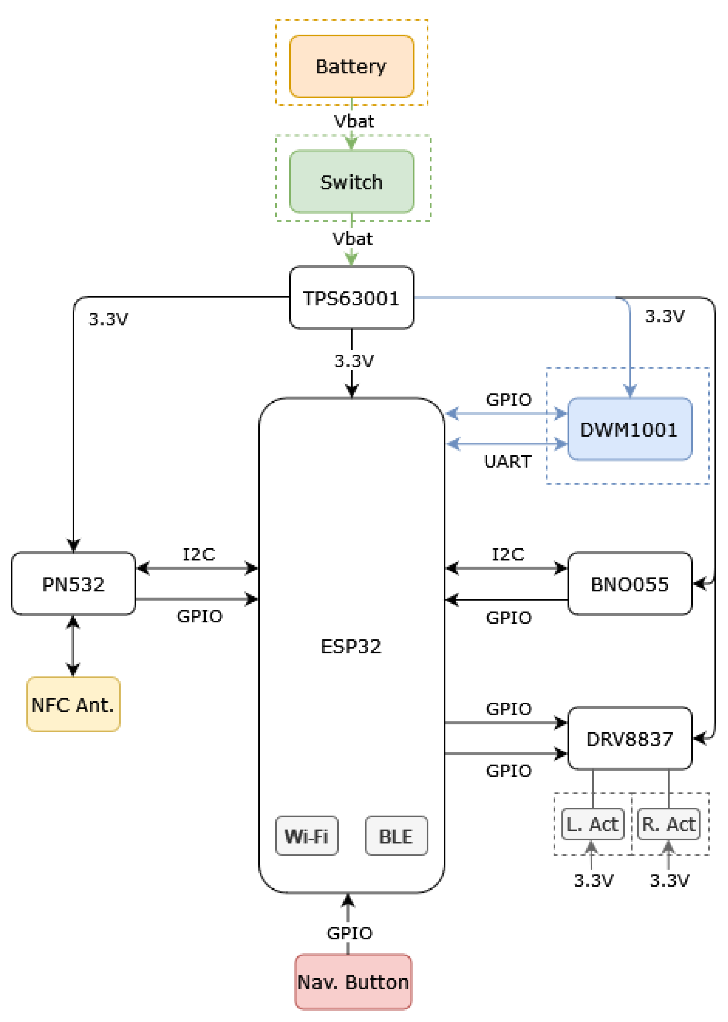
The overall architecture of the smart lifejacket is presented in
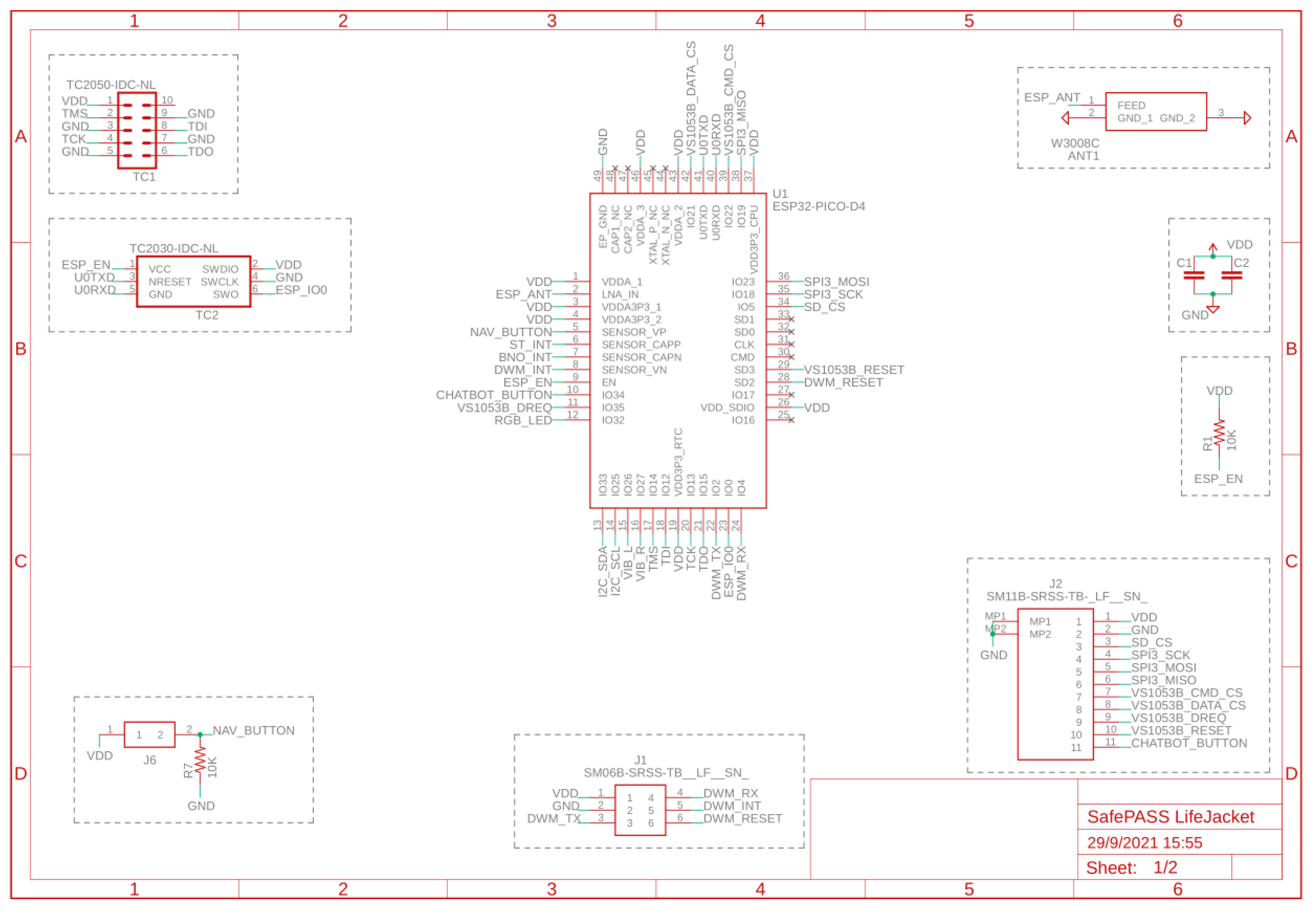
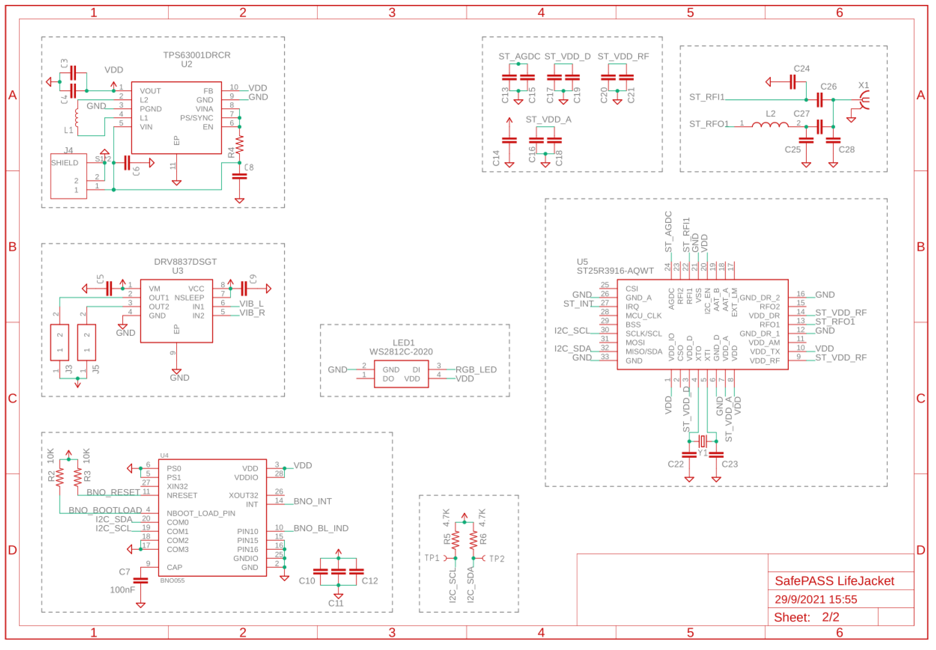
Figure 1. A Wi-Fi-and Bluetooth-capable microcontroller unit lies at the center of the system. Various peripherals are connected to it, providing localization, NFC, the actuators of the haptic navigation system and an IMU. The schematics are included in the
Figure A1 and
Figure A2.
A microcontroller unit was required to host the main program and communicate with the required peripherals. It was important to keep the cost low by having multiple interfaces for on-board communication with the various components. With that in mind, a device [
27] was selected which had both Wi-Fi and Bluetooth wireless interface integrated, both for cost reduction and to simplify and facilitate the design process. With these two interfaces, it became possible to connect to the ship’s central system, responsible for recording the location data and providing the route on request, as well as also any peripheral devices the passenger could have in order to gather additional information.
An ultra-wideband transceiver module [
28] was selected to carry out the indoor localization measurement. It contains firmware which abstracts the basic calculations and provides a final three-axis position to the MCU via UART. This technology was selected due to its properties which make it more suited for indoor localization than any alternatives, such as Bluetooth. The module has an integrated antenna and relies on preinstalled transceivers or anchors, which each have a known location for calculating to allow for position estimation in a coordinate system.
An advanced 3-axial 14-bit inertial motor unit was selected [
29] and connected to the MCU via
. It integrates multiple sensors and performs the fusion on-chip, thus reducing the load of the MCU and simplifying the development procedure. This module provides additional information to the smart lifejacket to help offset any measurement errors during the navigation procedure.
A low-power magnetic switch is responsible for activating the smart lifejacket. While the lifejackets are stored, the switch detects the magnetic field of a magnet, also located on the smart lifejacket, thus keeping the battery circuit open. When the lifejacket is removed from storage and unfolded, then the circuit is closed and the device is powered on. This is the simplest way to power on the device from an end-user perspective, instead of a traditional mechanical switch that the user has to remember to turn on.
A Near-Field Communication (NFC) reader module based on the PN532 controller [
30] was integrated on the lifejacket to allow for pairing with peripheral devices. The NFC controller communicates with the MCU via the
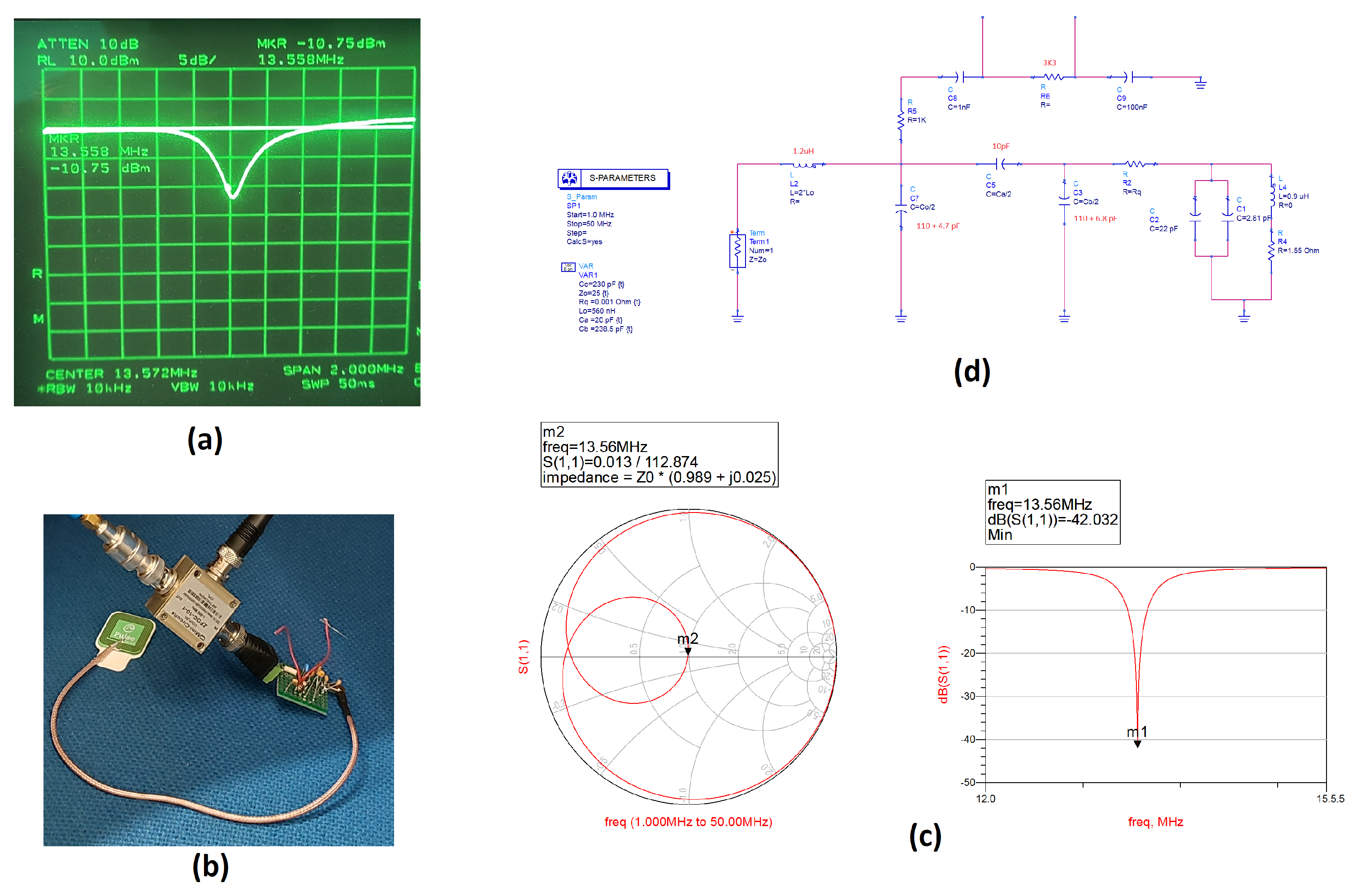
bus and utilizes an external antenna. The antenna is connected to the rest of the PCB via a cable to allow for placement independent of the PCB. In
Figure 2, the test fixture used to tune the antenna along with the simulation and measurement results is depicted. The antenna is tuned at a slightly higher frequency than the
MHz of NFC to compensate for the capacitance that will be added by the human body.
Additional components included a low-profile metal push-button to be used for activating the navigation functionality, as well as two vibration motors, left and right, to help navigate the passenger through the route by means of haptic indications.
2.2. Integration
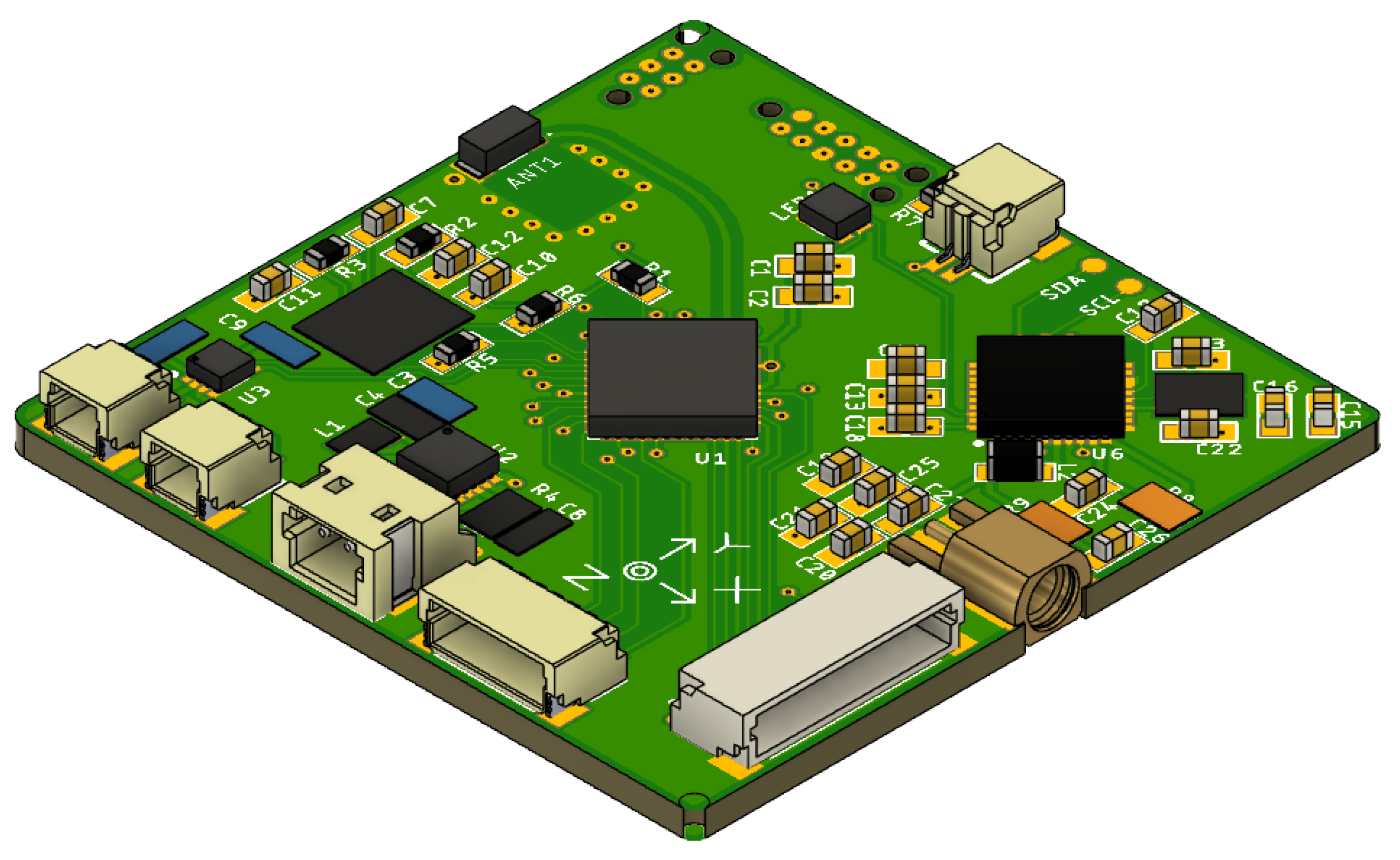
A PCB was designed to include as many components as possible in an effort to minimize the space requirements. The final design of the board is shown in
Figure 3. It contains the MCU, IMU and NFC reader and has connectors to the switch, battery, antenna, actuators and button, located in different parts of the lifejacket.
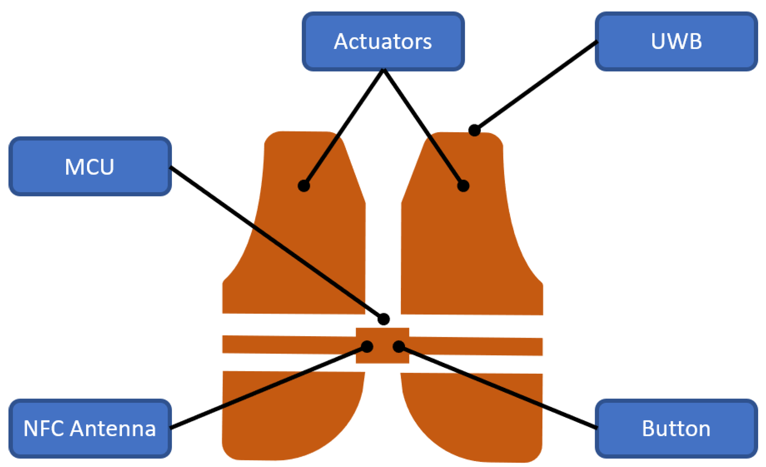
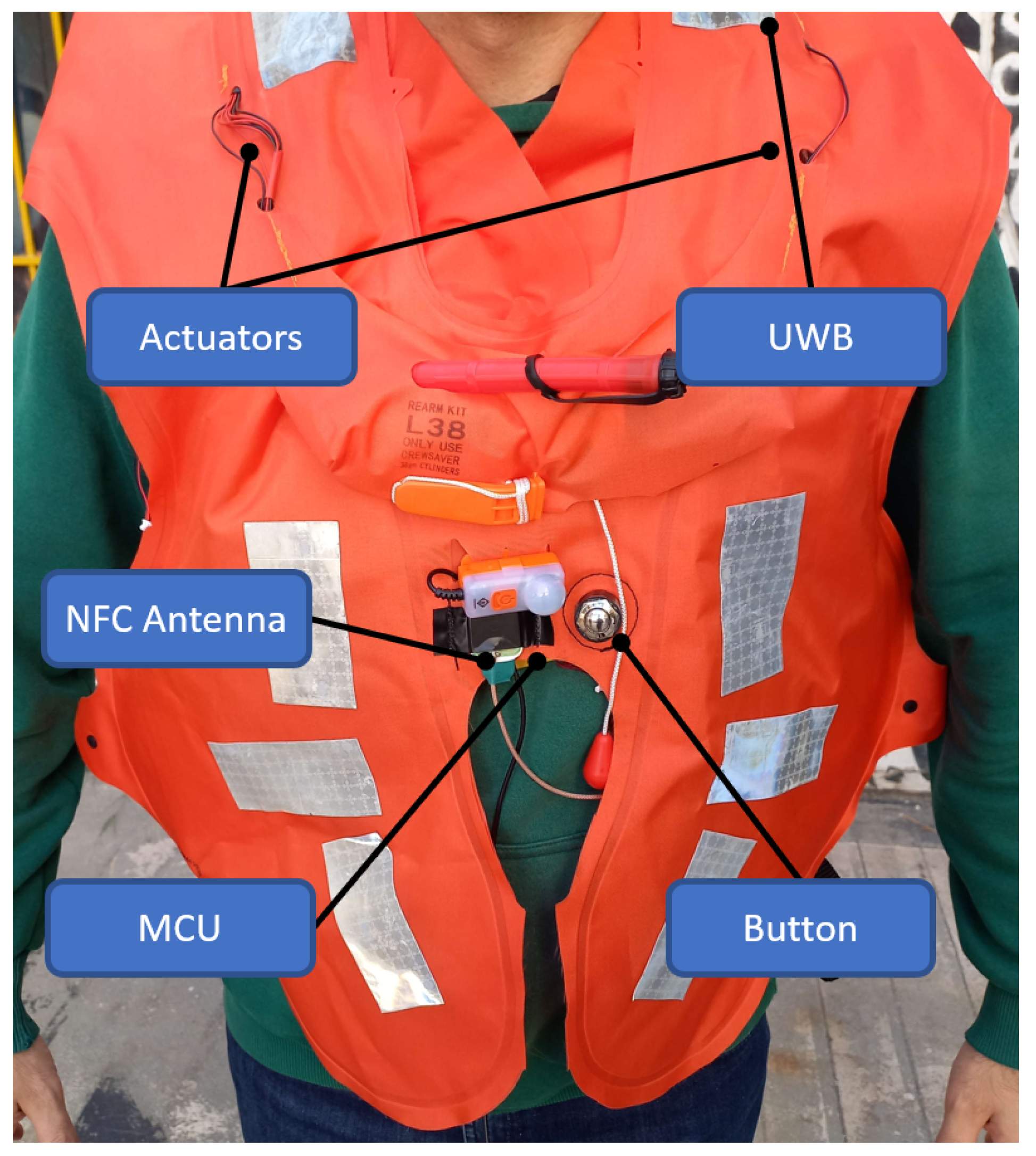
The placement of the main different parts is presented in
Figure 4. The ultra-wideband module was located on the back side of the lifejacket, as high as possible to ensure the best signal possible. The left and right actuators were located in front of the passenger so as to provide a clear direction indication. The navigation button and antenna were also placed on the front of the lifejacket to allow easy access to the user wearing it.
2.3. Software
The firmware for the smart lifejacket needed to incorporate multiple functionalities, all of which would require memory allocation, task scheduling and preemption, as well as intertask communication and synchronization in the form of flags and shared data structures. These included the following:
Indoor localization;
Wireless connection to a central system;
Clock synchronization;
Haptic navigation;
Detection and reading of near-field tags on a peripheral device;
Wireless connection to a peripheral device.
An open-source real-time operating system kernel [
31] was selected, both for its feature list and maturity, as well as its close integration with the microcontroller unit selected. A number of required API’s were already provided in the software tool set. Different functionalities for the navigation module were written as one or more separate tasks running concurrently and with potentially different priorities on the lifejacket to achieve the desired operation.
On initialization, the lifejacket attempts to connect to the wireless network and, having done that, synchronize and connect to the message broker. At the same time, it starts up the connection to the UWB, IMU and NFC reader, as well as other peripheral devices, and attempts to configure their operation as required. The localization module starts after the UWB module has been initialized and starts to poll it in order to obtain the calculated position.
A lightweight JSON [
32] protocol message format was designed to exchange messages with the central system over MQTT [
33], a good fit for the use case. Three basic messages were implemented: registration, data update and route request/response. With the exception of the route request, all messages do not require a response. Since the lifejacket guides the passenger on demand, there was a need for some type of RPC call over the underlying messaging protocol so that the lifejacket can receive a route which has as a starting point its current position.
In order to obtain a better position estimate, a linear Kalman filter was added to be run each time the UWB module was polled for a location estimate. This is a widely used technique to produce estimations from a noisy signal using a statistical model [
34,
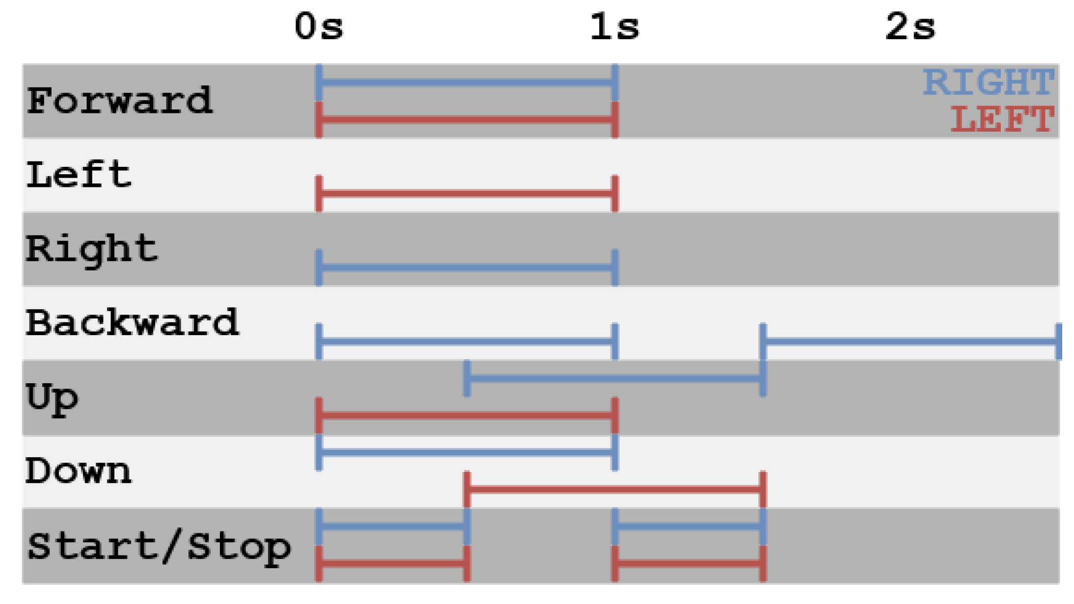
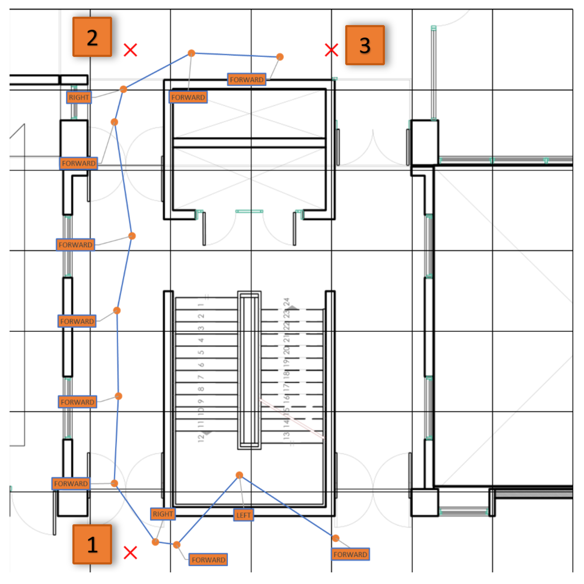
35]. It was considered suitable for the navigation component due to its small memory footprint and light computational requirements. It works by means of a feedback loop to calculate a measurement estimation based on sensor readings and the previous estimation. This way, the navigation algorithm has a smoother and more predictable calculation that is free from sensor noise to the extent that it is feasible. Ultimately, one such lightweight library was used to provide estimates for the location and speed of the user at each step. Navigation is provided to the user when it is requested by holding the push button. The application utilizes an RPC-style mechanism over the MQTT client to request a route from the central system. The latter replies with a list of points forming a route from the passenger’s current location, present at the original message, to a suitable destination. The route is parsed and the passenger is notified that the navigation procedure has started. While the navigation process is ongoing, a haptic signal is triggered when a timeout occurs, as long as a minimum speed is maintained, which serves to guide the passenger towards the next point in the route. When the passenger arrives at the point currently active at the route, an additional haptic indication is provided to them which helps navigate along sharp turns in confined spaces. These indications are in addition to the ones provided on a schedule, as previously mentioned. A different approach is used when the passenger needs to move between floors. When the next point is on a different height, the algorithm indicates that moving upwards or downwards is required without regard for where the passenger is facing. A graphical representation of the signals that the passenger receives during the navigation procedure are presented in
Figure 5.
3. Results
3.1. Assembly
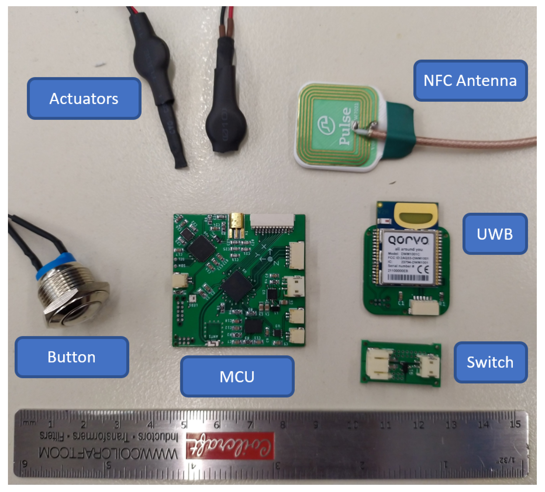
The firmware was developed and tested on development boards for each of the components used. When the design was finalized, the PCBs were designed and printed. All electronics components were placed and soldered on the boards. Nearly 20 complete devices were produced and tested for any manufacturing errors. After that, the firmware was loaded on the boards. Additional components such as buttons, actuators, connectors and cables were obtained and prepared for inclusion on the devices. The finalized main components of the smart lifejacket are shown in
Figure 6. The next step was to flash the final firmware for the MCU and UWB modules and, finally, mount everything on a lifejacket. The final result is presented in
Figure 7.
During all tests conducted from this point on, the data were sent to the back-end broker, where another pub/sub client would record all the information and respond to the lifejackets route requests. For the tests described in this section, the routes used were predefined, although they could easily be produced dynamically based on any operational and personal factors.
3.2. Localization
The LDER systems use the knowledge of the location of the passengers onboard the vessel’s decks to calculate evacuation routes, taking into account the current situation of the ship. Furthermore, knowledge of the position of each passenger is invaluable in locating stray or incapacitated passengers. The field of indoor positioning systems is a scientific area that has been and continues to be heavily researched. Among the many technologies tried, UWB offers the highest accuracy, but most importantly, can cope with multipath better than all of its competitor technologies [
36], an important feature given the highly RF-reflective environment created by metal vessels. This is due to the transceivers’ high bandwidth (500 MHz or 1 GHz), which leads to time pulses with a duration of less than 2 ns. Any multipath component that has traveled 60 cm more than the direct path can be easily discriminated because it arrives after the end of the pulse of the direct path.
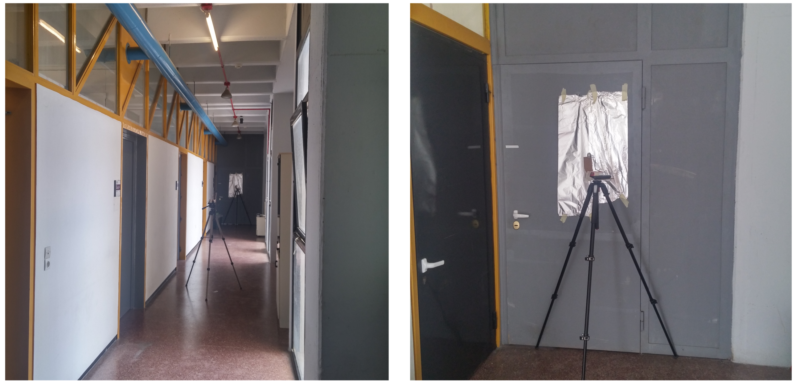
We tested the performance of the DW1000 transceivers by taking distance measurements in a hallway, which can be seen in
Figure 8, featuring an abundance of metal surfaces that create strong multipath components. In addition, we placed one of the transceivers in front of a door covered with aluminum foil and recorded the corresponding measurements with and without the aluminum foil.
The aluminum foil was placed 15 cm away from the transceiver, creating a strong multipath component that has traveled just 30 cm of added distance compared with the direct path. In
Figure 9, the error of the distance measurement with and without the aluminum foil is presented. It is observed that the mean error with the aluminum foil is less than 25 cm overall. Consequently, despite the fivefold increase in maximum measurement error from 5 to 25 cm, the absolute accuracy of the system remains sufficient for passenger localization and navigation.
In order to arrive at a location estimation, distance measurement is not enough. UWB technology is leveraged by installing devices on the smart lifejackets, called tags, that measure their distance from devices installed in fixed, well-known positions called anchors. The area over which we want to track a tag needs to be fitted with anchors, an arduous process with a lot of measuring involved. An important factor in the success of the localization process is the accuracy of the distance measurements and the availability of architectural plans for the area used.
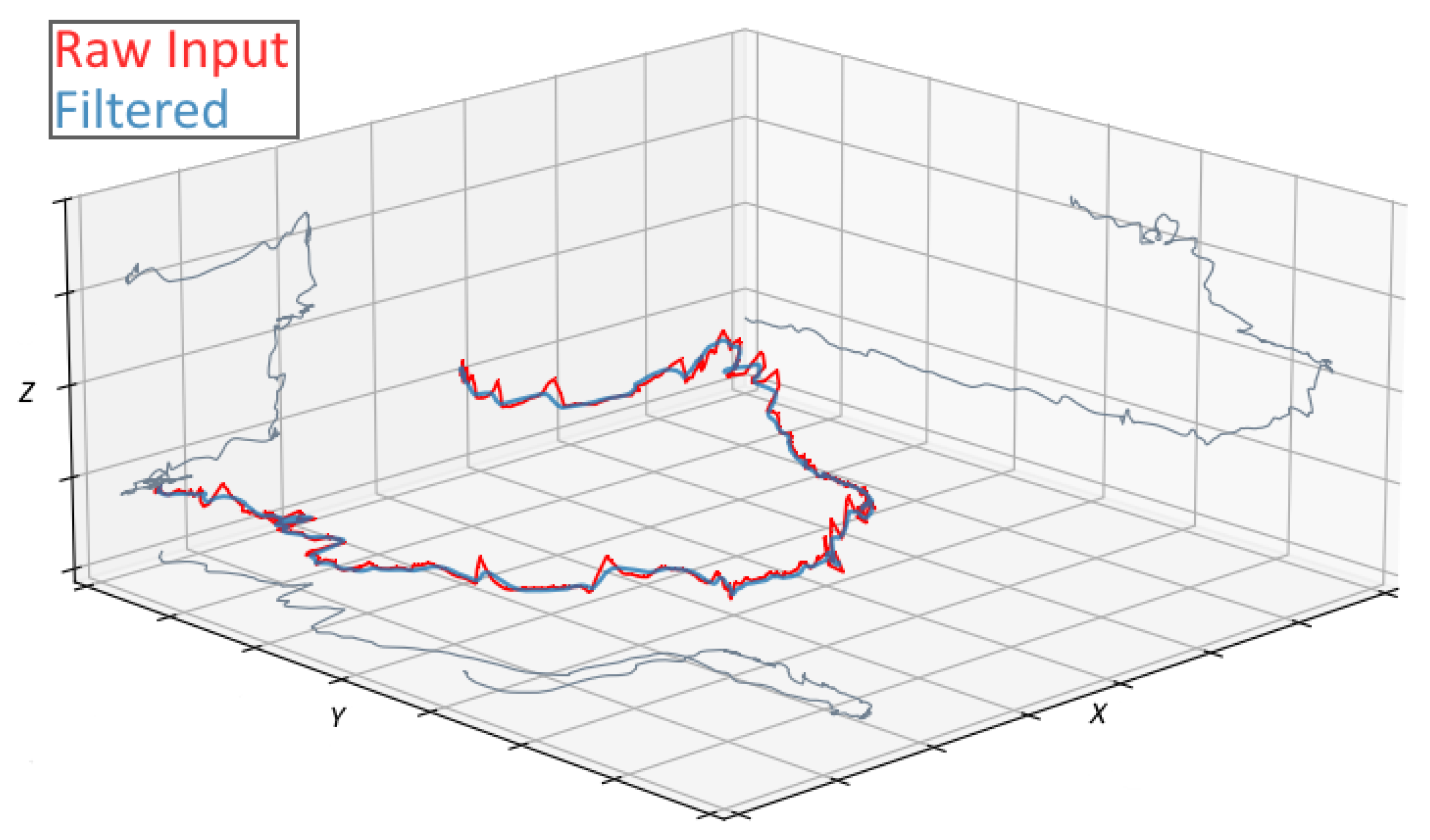
Tests were conducted to determine how to spread these anchors over the selected areas. Even with the improved accuracy of the UWB system, a Kalman filter was decided to be implemented, as described previously, in order to improve the quality of the measurements. After doing so, more tests were conducted to calibrate the behavior of the system. One such test is presented in
Figure 10. A user wearing the lifejacket walks along a corridor before ascending a flight of stairs to the floor above.
What is apparent is that, on a large ship, a passenger equipped with a smart lifejacket can be tracked with reasonable accuracy in real time. This allows for the crew to quickly identify passengers who might be lost or unable to move and quickly dispatch help, something which will shorten the evacuation time. Currently, unaccounted passengers have to be searched for by crew members or located using significantly less accurate localization systems. What is more, the accuracy of the indoor localization solution allows for navigation of the user in the confined areas of the vessel.
3.3. Navigation
The first navigation tests were carried out on a single plane of movement. The main issue was to test the output of the Kalman filter with regard to the navigation, as well as the timings between haptic indications.
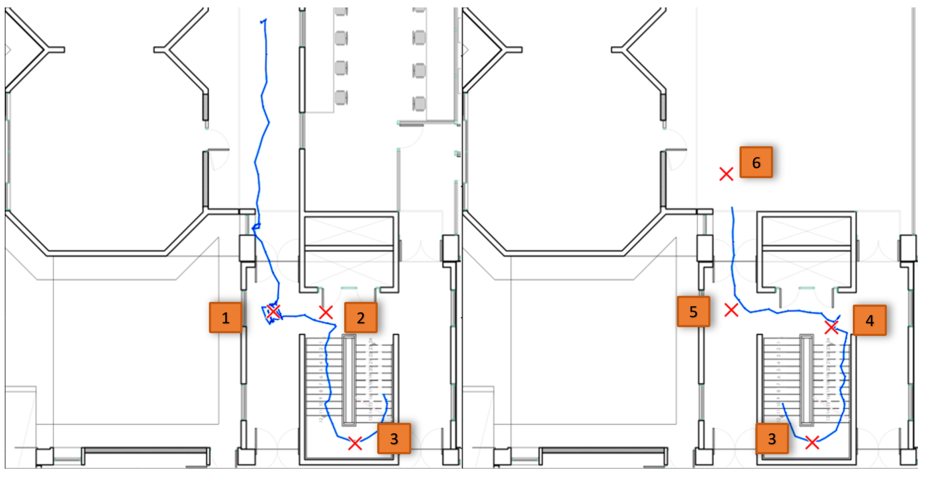
Figure 11 illustrates the results of one test. The estimated location is illustrated along with the indications given to the user. Some interference was observed due to objects in the area.
The testing phase involved localization and navigation in 3D space, namely movement between floors. The modified final version of the algorithm was used to guide users to the floor above. A sample of the results from the navigation is illustrated in
Figure 12. The extension for vertical navigation was simple, since the user could only move between floors using the stairs in known positions. Having only two vibration motors for conveying indications to move between floors proved to be slightly less trivial than the indications for a single floor.
Finally, a small number of volunteers were asked to use the haptic navigation feature, and early results were promising. For the most part, after a brief explanation of the different haptic cues, the volunteers were able to follow the short route with little issue. The route was approximately 37 m long and included a floor change. After discarding measurement errors, the results for the 13 test subjects are presented in
Table 1.
After the tests, the participants provided their feedback concerning the performance of these technologies under realistic evacuation scenarios, as well as the perceived ease of use and helpfulness. Positive results were obtained for both the smart lifejacket and the haptic navigation functionality, indicating the overall acceptability of this technology. More specifically, the participants were asked to evaluate the usability of the smart lifejacket following a 1-to-5 rating scale, with 1 corresponding to “strongly disagree” and 5 corresponding to “strongly agree”. The respondents generally agreed that the smart lifejacket was easy to don (mean = 4.54), comfortable to wear (mean = 4.23), that it easily connected with the smart wristband (mean = 4.15) and that it was easy to activate the navigation button (mean = 4.85).
In addition to the usability of the smart lifejacket, the respondents’ perception on the helpfulness of the haptic navigation was also collected with very positive results. In general, respondents strongly agreed that the haptic navigation on the smart lifejacket was very helpful in the scenario performed during the validation campaign (mean = 9.38). Moreover, they indicated that the haptic navigation would be helpful in a real-life evacuation of a large passenger vessel (mean = 8.77). When asked about the helpfulness of the haptic navigation in case of a real evacuation where they would have been separated from their group and lost, respondents also ranked the haptic navigation as very helpful (mean = 9.08). The detailed results are presented in
Table 2.
Despite the generally favorable feedback, there were a number of comments which indicated that more work is required in order to make the lifajackets more usable. Most of these were focused on the difficulty to distinguish between the different haptic instructions, mainly as they pertain to vertical movement. However, from the tests, it is apparent that the possibility exists for passengers to navigate alone, without help from the crew, in the case they are lost but still able to reach the lifeboats on their own.
4. Conclusions
In this paper, we proposed a smart lifejacket for navigating passengers to mustering points or embarkation decks during vessel evacuations. A combination of haptic navigation, UWB localization technology, wireless connectivity and local processing capability is applied to a lifejacket, turning it into a lifesaving appliance capable of addressing some of the more challenging aspects of a vessel’s emergency evacuation procedure. Each passenger can receive a personalized evacuation route, one that takes into account both the status of the ship and the state of the individual, be guided through it in conditions of low visibility and have their position being made known to the ship’s personnel. The latter makes feasible the rescue of trapped or disabled passengers.
There are a number of limitations in the study. Due to practical considerations, it was not feasible to test the system on a broader scale or for an extended period of time. For similar reasons, it was not possible to test the devices with a sizable number of participants.
A detailed description of the smart lifejacket and its implementation was given, along with a presentation of the haptic navigation system and its operation.
Section 3 details the results of testing the navigation functionality and the successful guidance of the user to the intended location, as well as the key outcomes based on the evaluation process that was followed. Because of these encouraging results, it is our belief that the smart lifejacket we developed within the SafePass project has real potential to improve the evacuation procedure and preserve human lives, and its location–support technologies are viewed as being broadly acceptable and usable by both crew and passengers [
4]. In the future, we plan to focus on improving the navigation algorithm and user experience and, additionally, reduce the production cost, something which will hopefully facilitate the adoption by the maritime industry.
