1. Introduction
As it is known, beyond design basis severe accidents of water-cooled and water-moderated reactors of nuclear power plants are followed up by the core melting with corium formation, which is a melt of a radioactive mixture of uranium oxide, zirconium, steel, products of interaction between metals and oxidizing medium and other structural elements. The escape of corium outside the reactor facility under certain conditions is a real scenario due to the large amount of accumulated energy and the presence of decay heat [
1].
Obviously, in order to prevent such situation during a severe accident at an NPP, experiments should be conducted to study the interaction between corium and structural components of the reactor facility to improve understanding of running processes. For instance, such experiments are required in studies of in-vessel and out-of-vessel melt retention, which have been conducted and are underway as part of the design and implementation of systems to control severe accidents through cooling down, controlled movement and retention of corium both inside the pressure vessel and outside of it [
2].
In such experiments on the physical modeling of processes occurring during severe accidents, a corium simulator is used, the so-called “prototype corium”, a substitute with properties similar to real corium in most parameters, but the dose load on personnel is almost excluded (
hereinafter in the paper,
corium means “prototype corium”). Therefore, a key difference between the prototype corium and the real one is that the prototype is not a source of heat, i.e., there is no self-sustaining radioactive decay in the prototype corium [
3].
In this regard, not only should the correspondence of the composition of the corium prototype to the real one be taken into account to ensure the modeling conditions are as close as possible to the full-scale ones, but, also, the energy release in the melt at a given level [
4]. The Lava-B experimental facility, available in the NNC RK [
5,
6], allows the conducting studies of the end-stage of a severe accident with core melting.
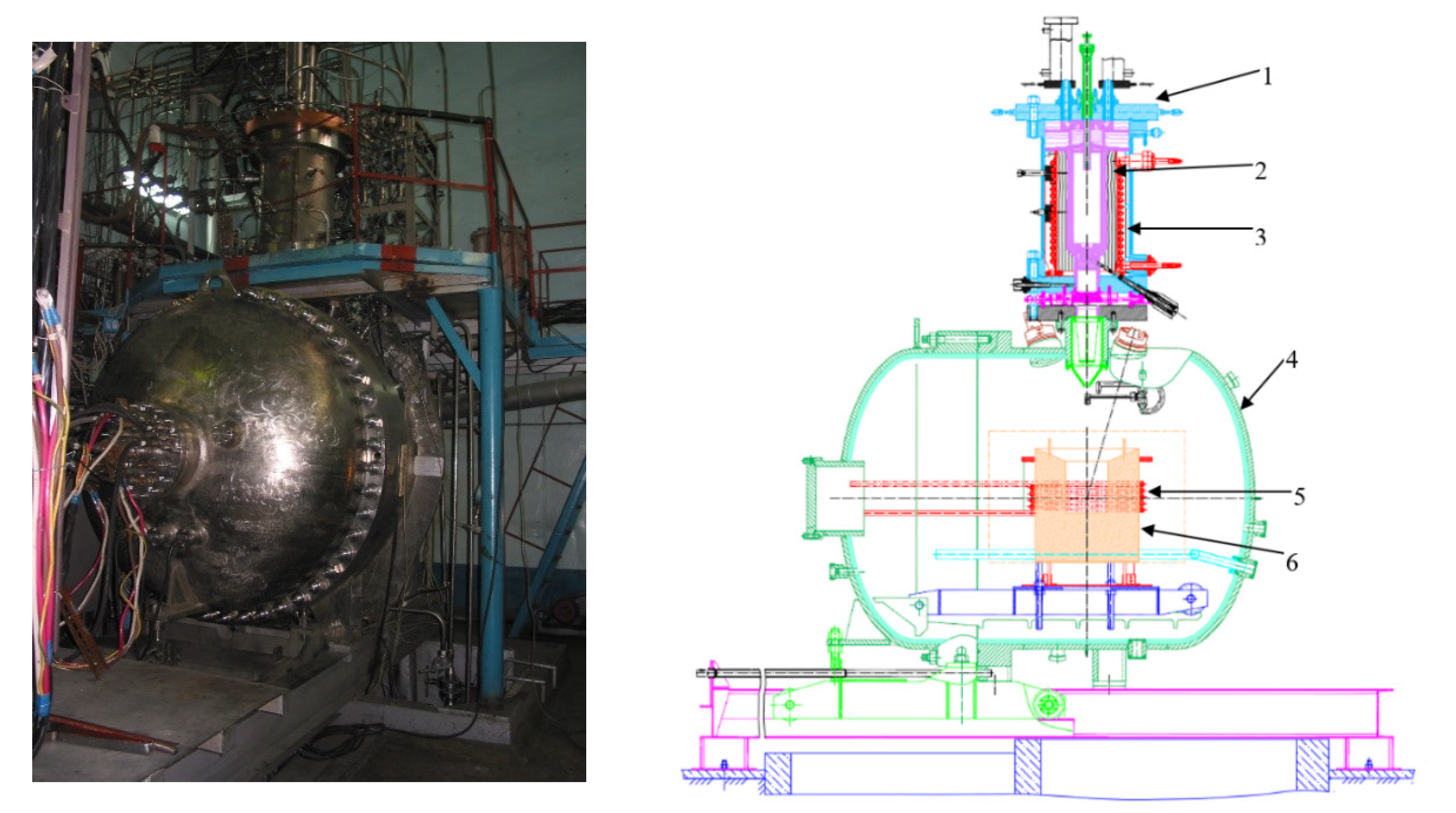
Figure 1 shows the physical form and layout of the Lava-B facility. The corium produced in an electric melting furnace (EMF) is drained into a melt trap located in the MR for further studying of its interaction with various structural materials. The trap is inserted in an inductor, which is used to simulate the decay heat in the corium in standard order.
A structural feature of the Lava-B facility is that inductors of the EMF and MR are driven with a single variable frequency drive VFD 500-2.4-10000 with a capacity of 500 kW. According to our reckoning, the power of the MR’s induction heater can be sufficient not only to simulate the heat decay, but, also, to directly produce corium in the volume of the melt trap.
A mechanism for destroying the crucible plug was mounted in the bottom of the EMF (
Figure 2). Operating principle of destruction devices is pneumomechanical. A striker (3) driven by the gas flow, moves a firing pin (1), which strikes the graphite plug, destroying it. The firing pin is returned to its original state by a spring which, as the striker moves in the direction of the plug, is compressed and, after impact on the plug, is released, pushing the striker backwards.
In some experiments, cases of incomplete melt draining into the experimental section had taken place, which violated the experiment conditions. There were moments when the plug did not chip even after several attempts. In such cases, it was decided to stop the experiment, and preparation of the facility for a second experiment began. All of these factors lead to the loss of both time and finances, since some parts of the EMF can be used only once in the experiment (for example, a graphite crucible).
Producing of the corium in a melt trap enables melting under controlled conditions, eliminating the need to prepare and drain the corium into a melt trap from EMP, which, as a rule, is associated with a number of technical complexities.
Previously, in [
7,
8], future large-scale experiments at the Lava-B facility were described. To test the applicability of the proposed approach in the planned experimental studies, we conducted an experiment at the Lava-B facility.
Thus, the purpose of the experiment is to experimentally confirm the possibility of producing corium by induction heating directly in the MR’s melt trap.
2. Research Method
To assess the thermal state of the experimental device and determine the conditions for the experiment, a computer simulation of induction heating of the loaded burden at a stationary level of the inductor power was performed. The purpose of the simulation was to confirm the feasibility of testing with the considered device design and the volume of burden’s materials. A value equal to 2500 K was taken as the achieved temperature of the corium, based on previous experiments in the Lava-B facility with a similar burden composition [
9,
10].
Computational studies were conducted using the ANSYS software package, based on the finite element method [
11]. Based on the design of the MR’s melt trap, a two-dimensional axisymmetric model was developed, which allows calculating the thermophysical parameters at control points.
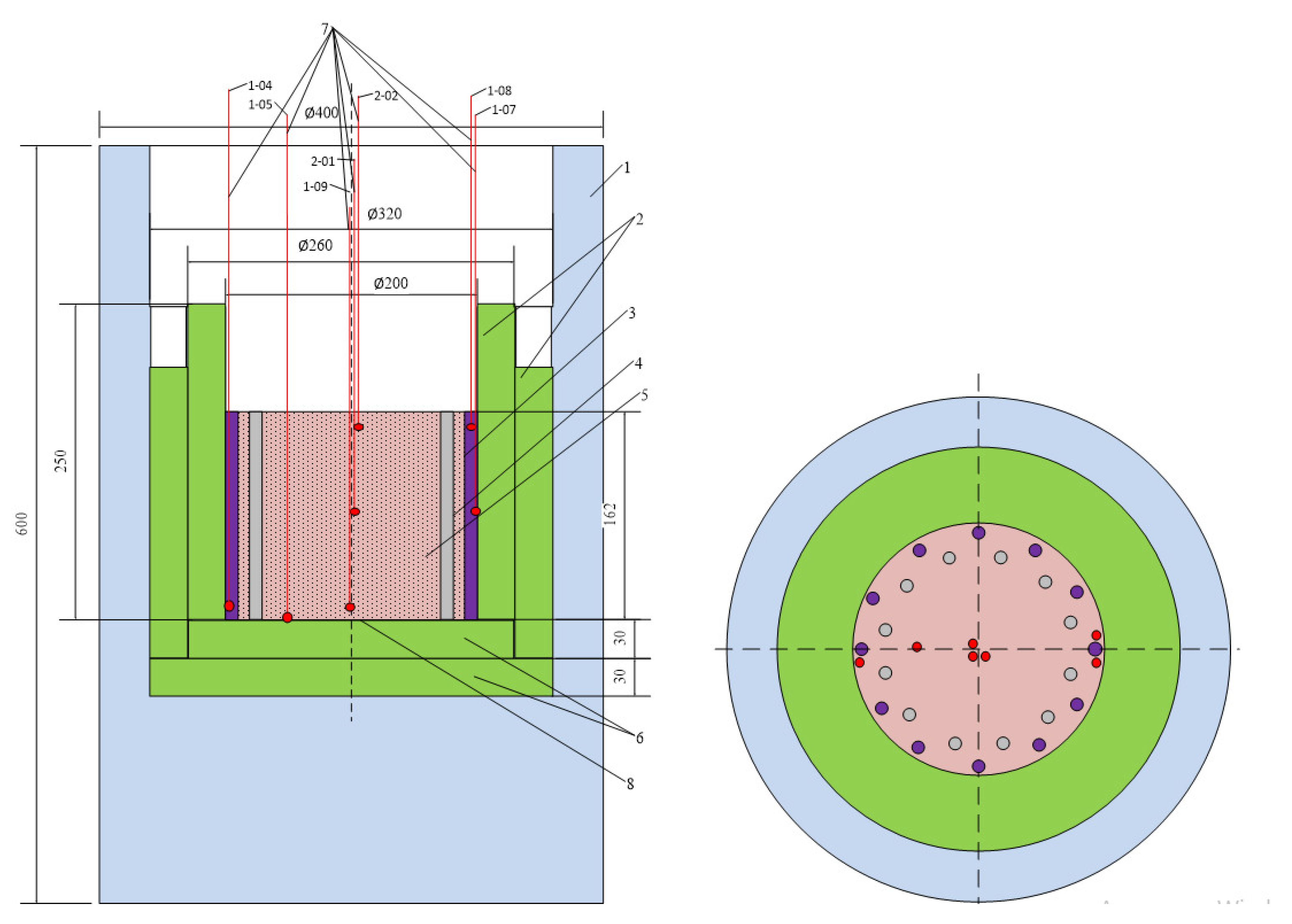
Figure 3 shows a diagram of such an experimental device.
The melt trap is a cylindrical concrete structure inserted in the MR’s inductor. A composition of materials for producing the corium with a total weight of 30.0 kg was loaded into the concrete trap.
The number of materials loaded into the trap:
- -
Uranium dioxide (UO2), kg………………………………………16.5;
- -
Zirconium (Zr), kg…………………………………………………7.5;
- -
Zirconium dioxide (ZrO2), kg……………………………………1.5;
- -
Steel (SS), kg ………………………………………………………4.5.
The initial data of induction heating for simulation were selected based on the averaged parameters of previously performed experiments [
12,
13]. By taking into account the technical capabilities of the Lava-B facility:
- -
The active power of the inductor was 120 kW;
- -
The inductor electrical efficiency was 45%;
- -
The inductor power factor was 0.9 considering the compensation.
Therefore, the heat release in the melt was set depending on the characteristics of induction heating—the surface effect of penetration into the depths of materials of the conductive medium during induction heating, or the skin effect (in this calculation, 70% of the total heat release occurred on the surface layer). At the same time, the depth of this surface is determined by the theory of induction installations [
14].
The prototype of the corium is a burden consisting of several components. Considering the complexity of induction heating, it is impossible to fully take into account its effect on each of the burden components when computer modeling. Hence, a significant simplification is made. The trap load or the future corium is presented as a single-structured material. Some properties of the corium were used in computer modeling based on their sources [
15,
16]. It should be noted that its value was assumed to be a constant in the calculations due to the lack of information on the dependence of the corium thermal conductivity on temperature. In this case, the value of the thermal conductivity coefficient was set similarly to the earlier calculations of corium heating within the framework of the ISTC Project No. K-1265 using the INVECOR program [
17,
18].
The described method of decay heat simulation in the corium prototype was validated earlier and, therefore, it can be applied for a non-stationary calculation of temperature changes in the trap components [
19,
20].
The thermophysical properties of the trap components were used according to the literature source [
21].
When simulating, the following control points were selected: c.p.1, c.p.2, c.p.3. Their layout corresponds to the layout of the thermocouples 1-04, 1-07, and 1-08 in the melt trap, (
Figure 3) based on the symmetry condition.
Based on the presented results of the computer simulation, the conditions for conducting physical modeling of corium production in the MR’s melt trap were determined.
In order to provide conditions for a controlled environment during the experiment, the measured temperature and power of the induction heater were chosen as the main control parameters. The components were heated by raising the voltage on the MR’s inductor to 900 V (rate: 100 V/min, N ≈ 120 kW), while the integral amount of energy supplied to the burden in the concrete trap, the average value of the maximum power supplied by the constant speed drive (CSD), and the values of the melt temperature during the experiment should correlate with the results of the computer simulation. To control the temperature in a concrete trap, tungsten–rhenium thermocouples of 5/20 graduation are used as measuring instruments (
Figure 3).
3. Research Results and Discussion
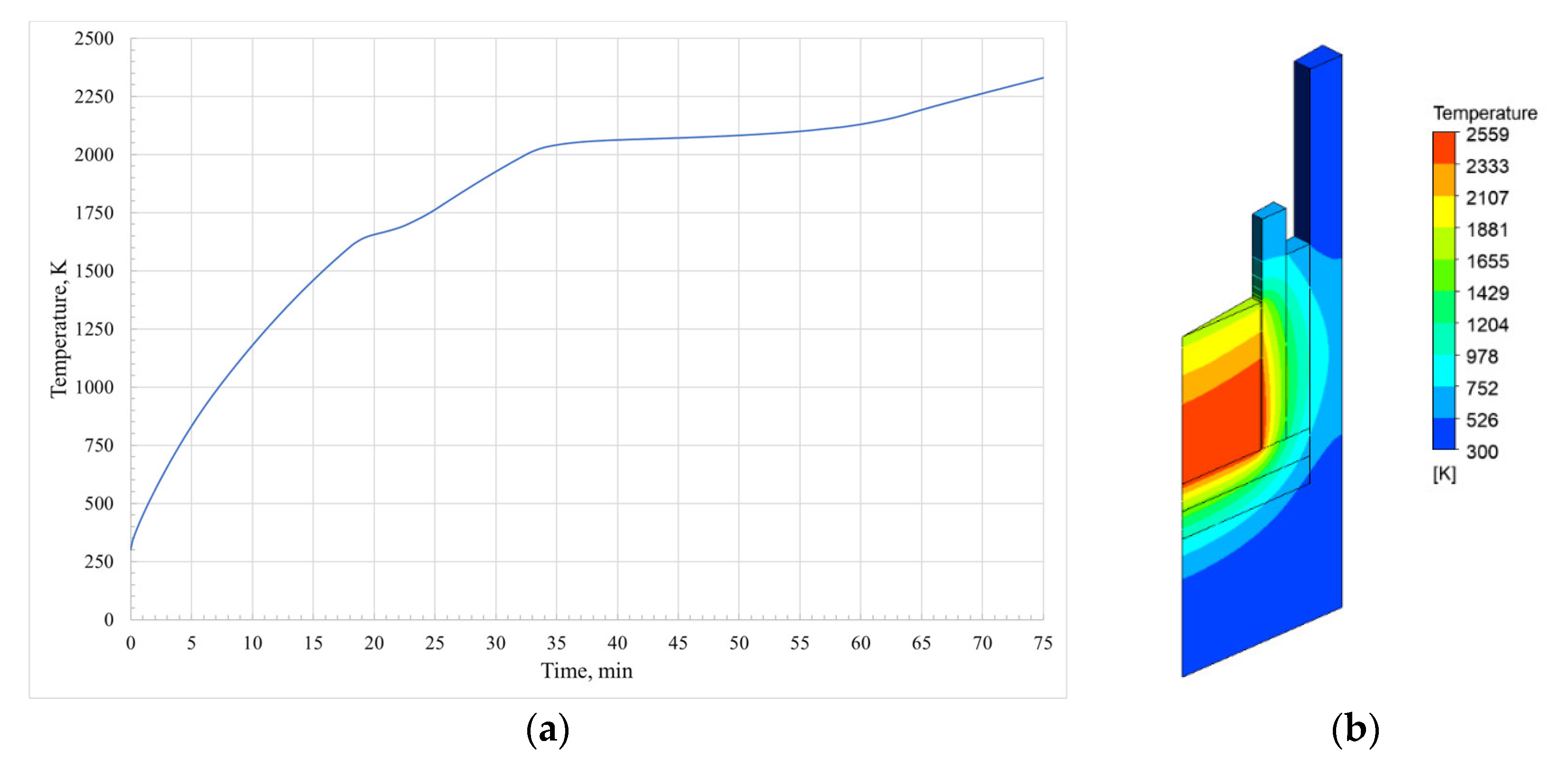
When conducting the computer simulation of the induction heating of the burden at the set power level of the inductor, the temperature at the control points reached 2500 K in ~75 min after the start of heating. Therefore, the average temperature of the resulting corium was ~2350 K.
Figure 3 shows the results of computer simulation.
Figure 4a shows a diagram of change in the average temperature of the corium over time at the set power of the inductor. As the diagram shows, approximately 20 min after the start of heating, the increase in the average temperature stopped (the diagram becomes flat). This process took about 5 min and indicated a phase transition of one of the corium components. Indeed, by paying attention to the temperature at which the phase transition occurred, it became evident that this was steel. The melting temperature of the steel 12C18N10T used in the experiment was ~1703 K.
A similar situation was observed approximately 35 min after the start of heating. As in the first case, the melting of the corium component began at this point in time, and, in this case, it was metallic zirconium. The melting processes in the trap should complete approximately 60 min after the start of heating. The temperature at one of the control points should reach 2500 K at approximately 75 min.
Figure 4b shows the temperature field of the calculation model at the time of 75 min. The average temperature of the corium was 2350 K with a maximum temperature of 2559 K.
Analysis of the temperature field showed that the temperature of the outer surface of the concrete section reached temperatures above 700 K. A high level of temperature gradient between the corium and the outer wall of the concrete section can lead to the destruction of the experimental device due to thermal stresses. As illustrated below, this assumption was confirmed by a visual analysis of the concrete section state after the experiment.
Thus, the calculation showed that the temperature of the corium at the selected control points reached 2500 K 75 min after the start of heating with the given parameters of the MR’s induction heater of the Lava-B facility. The total integral amount of heat supplied to the corium is ~540 MJ.
After the computer simulation, an experiment was conducted to produce a prototype of corium in the MR’s melt trap.
Table 1 provides the main data obtained based on the experiment.
Therefore, the main parameters of the physical experiment correlated with the results of the computer simulation.
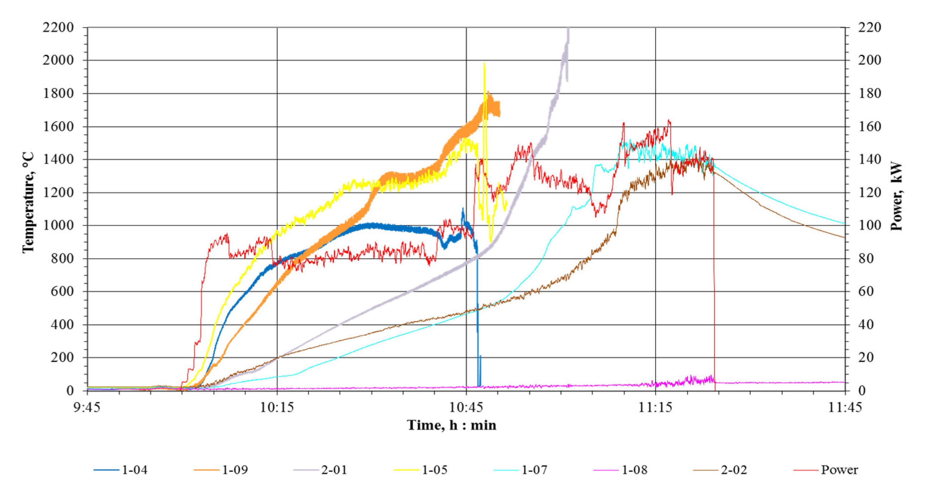
Figure 5 shows the diagram of the burden temperature in the trap. According to expectations, due to the features of induction heating, in particular the skin effect [
15], more intense heating occurred at the side walls of the refractory blocks, as shown by thermocouples 1-04 and 1-05. Thermocouple 1-08 failed.
As the presented diagram shows, at 50 min there were sharp changes in the thermocouple readings near the side walls of the refractory blocks. Thus, it is possible to make an assumption about the beginning of the melting process and the intense interaction of the burden components (probably, the melting of steel and zirconium). Thus, it could be concluded that the metal components became liquid and formed a corium pool in the melt trap within an hour after starting the experiment.
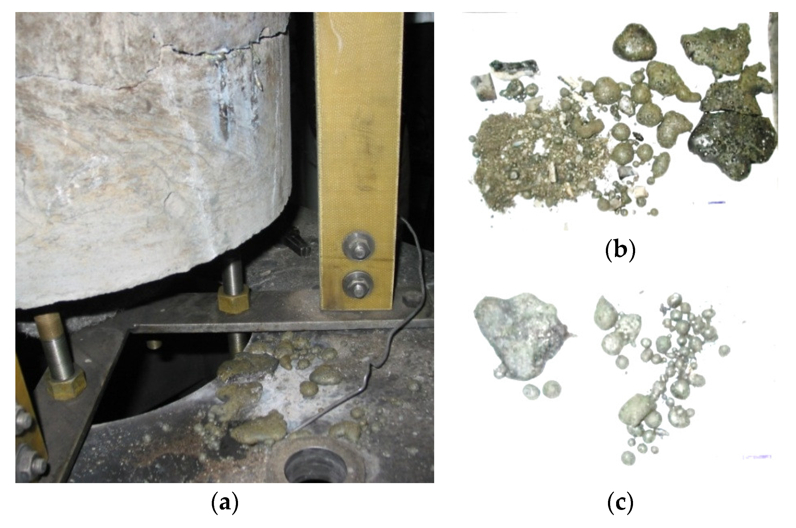
Visual confirmation of the melting of the corium components were the smudges of the solidified melt revealed after the opening of the MR, which escaped through one of the horizontal cracks in the lower third of the concrete trap (
Figure 6).
At the same time, as it was supposed in the course of computer simulation, the inductive heating of the corium led to the formation of overheated regions and thermal stress centers in the concrete wall of the trap. Due to the thermal stresses that occurred in the wall of the concrete trap, cracks formed through which the melt flowed out of the trap into the MR. (
Figure 7).
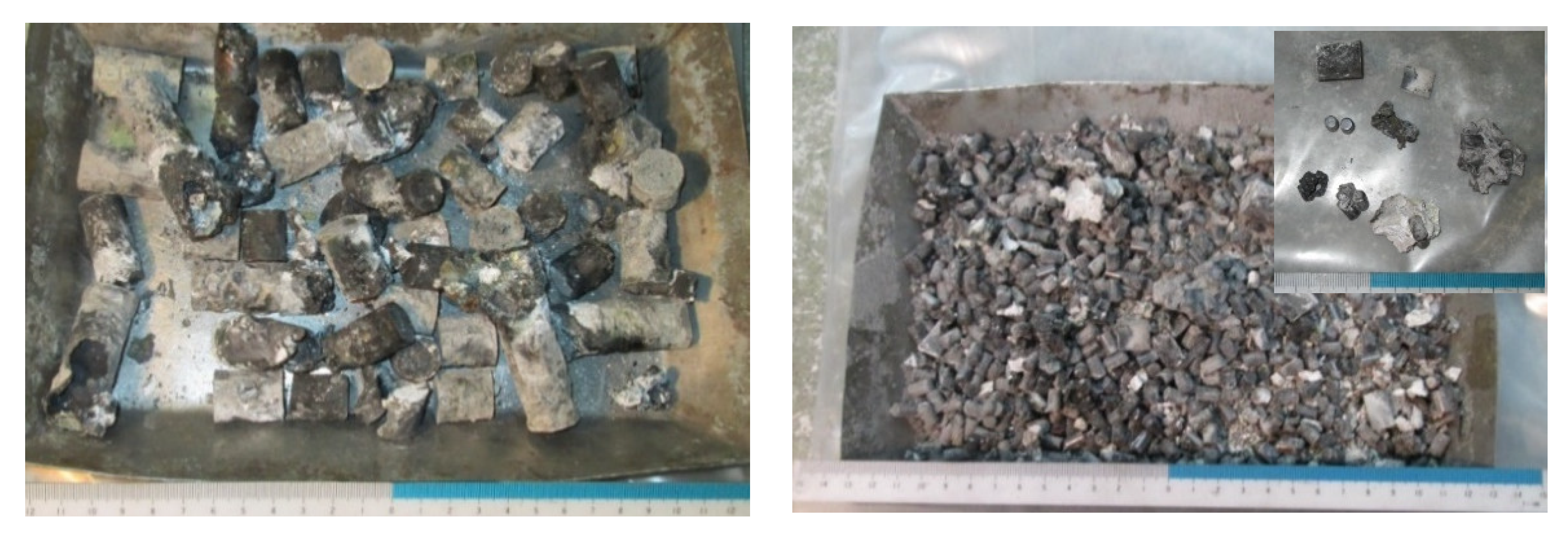
When studying the burden material resulting from the heating, its components were removed layer by layer in two stages.
Figure 8 shows the removed material.
At the first stage, fragments of steel and zirconium loading rods were removed (
Figure 8, left), which were the remains of vertically located loading rods melted from below. Following these were the partially sintered fragments of the dispersed components of the mixture (uranium dioxide pellets, zirconium dioxide powder, zirconium plates) (
Figure 8, right).
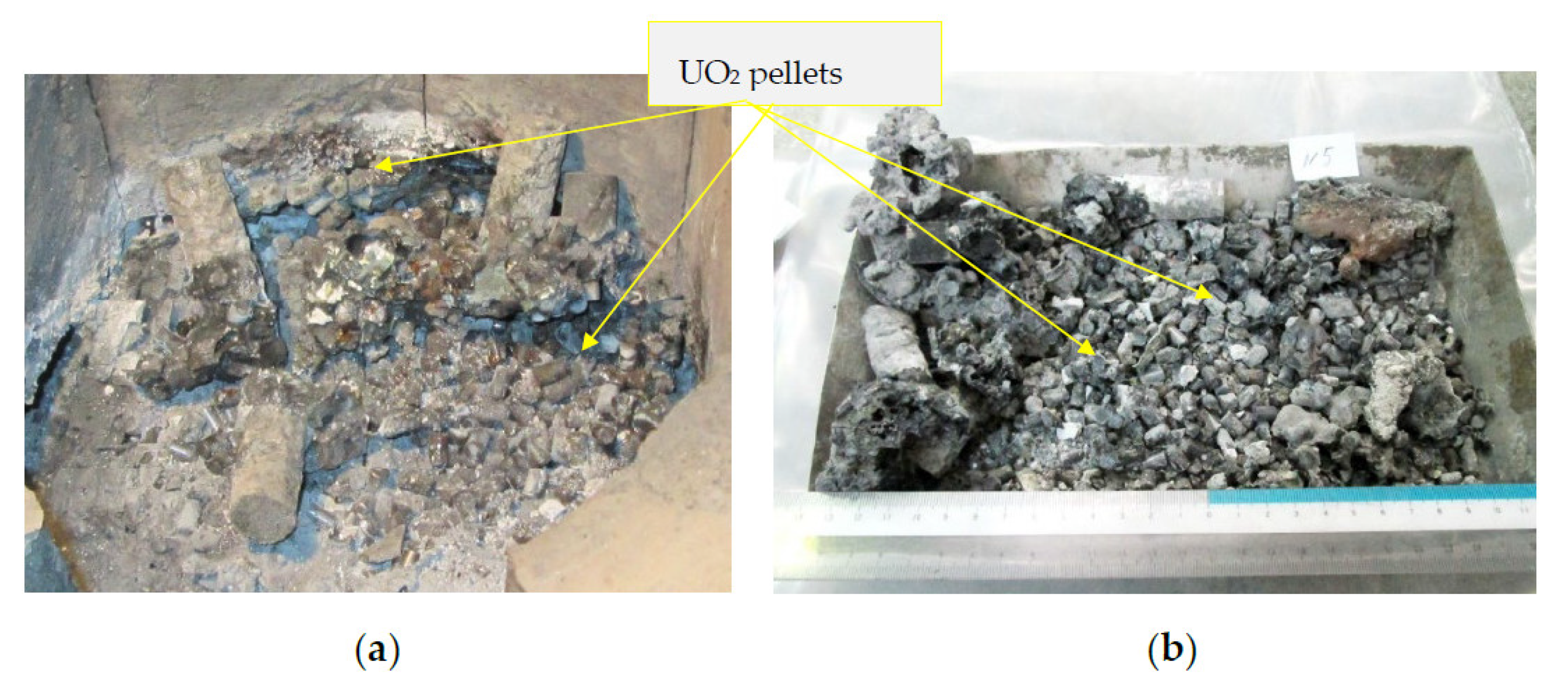
In the second stage, the remains of the vertical loading rods were removed, melted at or slightly below the maximum protruding level of the compacted burden. The removal led to the separation of part of the burden fragments that had undergone melting, which formed a “crust” from uranium dioxide pellets bound by a metal melt (
Figure 9).
Based on the study of the produced corium, as
Figure 8 and
Figure 9 show, it can be concluded that the components of the burden in the concrete trap were not completely melted. Fragments of the steel and zirconium rods, as well as partially sintered fragments of the dispersed component of the corium, turned out to be unmelted.
4. Conclusions
Thus, computer simulation of the induction heating of the corium components in the melt trap showed that the power of the inductor can be sufficient to directly obtain a melt and, subsequently, maintain the corium in the liquid phase. Based on the performed calculations, the conditions for the physical modeling of the corium production in the MR’s melt trap of the Lava-B experimental facility were also determined.
The results of a physical experiment to study the possibility of forming a corium pool by induction heating in the melt trap of the Lava-B facility showed that its metal components became liquid and formed a melt pool during induction heating of the burden in the trap. These processes were confirmed both by analysis of the diagram of temperature changes in the experiment and by visual means. However, not all components forming the corium in the concrete trap were completely melted. This can be explained by heat losses due to radiation into the MR medium, as well as thermal interactions with the trap walls, which are much colder than the melt. A high temperature gradient between the walls of the trap and the corium leads to thermal stresses that destroy the trap. The melt escapes through the cracks outside the trap in the MR. In this regard, it can be concluded that the proposed method for obtaining corium without making additional design decisions is not applicable in the case of using this design of the trap.
Nevertheless, based on the analysis of both the computational and experimental study, it can be concluded that the proposed method for producing corium is potentially feasible. However, at this stage, there are problems associated with the complete melting of all the components of the corium, as well as with the integrity of the experimental device during the formation of the corium pool and during the direct simulation of the physical and chemical processes of a severe accident.
Concluding the results of the studies of the corium producing method and its retention in the MR’s melt trap of the Lava-B facility, the following proposals for its implementation can be presented:
- (1)
Apply measures to reduce heat loss by radiation from the surface of the burden/corium in the experimental device;
- (2)
Increase the volume of the liquid phase of the corium, and conduct additional studies with varying the configuration of loading materials and the power diagram of the induction heater. The results of these studies will contribute to a gentler formation of the liquid phase of the burden metal components without its overheating and subsequent dissolution of the “dispersed component” of the burden;
- (3)
Strengthen the design of the experimental device in order to increase its structural resistance to high thermal stresses, and, as a result, maintain integrity in the course of the experimental studies.
Author Contributions
Methodology, M.B.; software, K.T.; validation, A.A.; investigation, I.K. and M.B.; resources, M.B.; supervision, M.S., V.B., A.G. and O.S.; project administration, M.B. All authors have read and agreed to the published version of the manuscript.
Funding
This research was funded by the Ministry of Energy of the Republic of Kazakhstan, BR09158470.
Institutional Review Board Statement
Approved by the ethics committee of the Institute of Atomic Energy.
Informed Consent Statement
Informed consent was obtained from all subjects involved in the study.
Data Availability Statement
The data used to support the funding of this study are available from the corresponding author upon request.
Conflicts of Interest
The authors declare no conflict of interest. The funders had no role in the design of the study; in the collection, analyses or interpretation of data; in the writing of the manuscript; or in the decision to publish the results.
References
- Arutyunyan, R.V. Chinese syndrome. Nature 1990, 11, 35–41. [Google Scholar]
- Vasiliev, Y.S.; Vurim, A.D.; Zhdanov, V.S.; Zuev, V.A.; Kenzhin, E.A.; Kolodeshnikov, A.A.; Pakhnits, A.V. Experimental studies on modeling processes features of severe accidents on nuclear reactors conducted in IAE. NNC RK Bull. 2009, 4, 26–54. [Google Scholar]
- Journeau, C. Contribution des Essais en Matériaux Prototypiques sur la Plate-Forme PLINIUS à L’étude des Accidents Graves de Réacteurs Nucléaires; Sciences de L’ingénieur [Physics] Université D’Orléans: Orléans, France, 2008; 229p. [Google Scholar]
- Mukhamedov, N.; Skakov, M.; Deryavko, I.; Kukushkin, I. Thermal properties of prototype corium of fast reactor. Nucl. Eng. Des. 2017, 322, 27–31. [Google Scholar] [CrossRef]
- Nazarbayev, N.; Shkolnik, V.; Batyrbekov, E.; Berezin, S.; Lukashenko, S.; Skakov, M. Scientific, Technical and Engineering Work to Ensure the Safety of the Former Semipalatinsk Test Site, 3rd ed.; Worldwide Promedia: London, UK, 2017; 290p. [Google Scholar]
- Vurim, A.; Mukhamedova, N.; Baklanova, Y.; Syssaletin, A.; Akayev, A. Information and Analytical System for Processing of Research Results to Justify the Safety of Atomic Energy. Appl. Sci. 2022, 12, 9705. [Google Scholar] [CrossRef]
- Bekmuldin, M.; Skakov, M.; Baklanov, V.; Gradoboyev, A.; Akayev, A. Heat-resistant composite coating with a fluidized bed of the under-reactor melt trap of a light-water nuclear reactor. Eurasian Phys. Tech. J. 2021, 18, 65–70. [Google Scholar] [CrossRef] [PubMed]
- Skakov, M.; Toleubekov, K.; Baklanov, V.; Gradoboev, A.; Akayev, A.; Bekmuldin, M. The method of corium cooling in a core catcher of a light-water nuclear reactor. Eurasian Phys. Tech. J. 2022, 19, 69–77. [Google Scholar] [CrossRef] [PubMed]
- «Cormit-II» Project. Available online: https://www.nnc.kz/ru/news/show/215 (accessed on 16 November 2022).
- RT-11Expeiment. Available online: https://www.nnc.kz/news/show/250 (accessed on 16 November 2022).
- ANSYS Fluent User’s Guide, 15th ed.; ANSYS Inc.: Canonsburg, PA, USA, 2013; 2620p.
- Maruyama, Y.; Tahara, M.; Nagasaka, H.; Kolodeshnikov, A.; Zhdanov, V.; Vassiliev, Y. Recent results of MCCI studies in COTELS project. In Proceedings of the Third Korea-Japan Symposium on Nuclear Thermal Hydraulics and Safety, Kyeongju, Korea, 13–16 October 2002. [Google Scholar]
- Kolodehnikov, A.A.; Pivovarov, O.S.; Vassiliev, Y.S.; Zhdanov, V.S.; Zuyev, V.A.; Ignashev, V.I.; Mikisha, A.V. Research of severe accidents results of water-cooled power reactors on COTELS project. NNC RK Bull. 2002, 1, 5–17. [Google Scholar]
- Ivanova, L.; Grobova, L.; Sokunov, B.; Sarapulov, S. Induction Crucible Furnaces, 2nd ed.; Publishing House of USTU–UPI: Yekaterinburg, Russia, 2002; 87p. [Google Scholar]
- Asmolov, V.G.; Zagryazkin, V.; Astakhova, Y.V.; Vishnevsky, V.Y.; Dyakov, Y.K.; Kotov, A.Y.; Repnikov, V.M. Density of UO2–ZrO2 melts. High Temp. 2003, 41, 714–719. [Google Scholar] [CrossRef]
- Poznyak, I.; Shatunov, A.; Pechenkov, A. Measurement of the Electrical Conductivity of the Corium melt. Proc. St. Petersburg Electrotech. Univ. J. 2008, 39–45. [Google Scholar]
- ICTS Project #K-1265 INVECOR (IN-VEssel Corium Retention in Accident of Water Reactor). Available online: https://istc.int/ru/project/DA8802253C138C29C3257052005303CF (accessed on 16 November 2022).
- Baklanov, V.V. Instrumental and Measuring Complex for Studying the Interaction of Materials in a Nuclear Reactor during Severe Accidents: A Thesis for the Degree of Candidate of Technical Sciences, Yurga Technological Institute, TPU, Yugra. 2016. Available online: https://portal.tpu.ru/portal/pls/portal/!app_ds.ds_view_bknd.download_doc?fileid=4000 (accessed on 16 November 2022).
- Toleubekov, K.O.; Khazhidinov, A.S.; Akaev, A.S. Simulation of induction heating by simulating residual energy release in corium when interacting with heat-resistant materials. NNC RK Bull. 2021, 1, 9–14. [Google Scholar] [CrossRef]
- Ramazanova, K.M.; Zuev, V.A.; Ganovichev, D.A.; Khazhidinov, A.S.; Akayev, A.S. Calculation of the Temperature Field of the Corium and Refractory Blocks of the Melt Trap of the Lava-B Facility. NNC RK Bull. 2016, 134–139. [Google Scholar]
- Chirkin, V.S. Thermophysical Properties of Nuclear Engineering Materials; Publishing House Atomizdat: Moscow, Russia, 1968. [Google Scholar]
| Disclaimer/Publisher’s Note: The statements, opinions and data contained in all publications are solely those of the individual author(s) and contributor(s) and not of MDPI and/or the editor(s). MDPI and/or the editor(s) disclaim responsibility for any injury to people or property resulting from any ideas, methods, instructions or products referred to in the content. |
© 2023 by the authors. Licensee MDPI, Basel, Switzerland. This article is an open access article distributed under the terms and conditions of the Creative Commons Attribution (CC BY) license (https://creativecommons.org/licenses/by/4.0/).


 ,
, 


