Abstract
Among renewable energy technologies, wind energy features one of the best possibilities for large-scale integration into power systems. However, there are specific restrictions regarding the installation areas for this technology, thus resulting in a growing, yet restricted, rate of penetration of the technology because of the limited viable sites onshore or in shallow waters. In this context, the use of offshore semi-submersible platforms appears as a promising option, which additionally enables the incorporation of other elements, such as wave energy converters or aquaculture. Nevertheless, this kind of offshore facility involves interactions between platform movements and the wind turbine, increasing the complexity of the system, causing traditional control techniques to not be able to fully cope with the dynamics of the system, and thus limiting the efficiency of energy extraction. On the contrary, the use of intelligent control techniques is an interesting option to take full account of the said interactions and to improve energy capture efficiency through the control of the pitch of the blades, especially under turbulent, above-rated wind profiles. This work presents an original fuzzy logic controller that has been validated by comparing it with previously validated controllers, following a developed methodology that allows comparison of controllers for wind turbines in semi-submersible platforms using performance indexes.
1. Introduction
Increasing the generation of energy using renewable sources is a key political measure already adopted by both developed and developing countries. In this context, wind energy is considered a technology with huge possibilities for industrial exploitation, maturity, and large-scale integration into the power systems [1,2]. In this sense, offshore (marine) wind farms feature advantages over onshore (land) facilities with regard to the power obtained and environmental impact. Given that appropriate sites on the continental shelf are limited, placing wind turbines in deep water turns up as a feasible option, as different floater solutions have demonstrated, each with its own pros and cons [3]. Among these floating structures, the installation of wind turbines on semi-submersible platforms is a promising alternative, as studied in [4], which allows secondary uses such as aquaculture or tidal energy. Non-fixed foundations have attracted a lot of attention, particularly from Europe [5].
The worldwide wind energy installed capacity was forecasted to reach 217 GW by 2020 and 414 GW by 2030 [6], but this moderate scenario has been surpassed by far, as installed wind energy facilities accounted for 563 GW in 2018, 23 GW of them corresponding to offshore facilities [7]. As an example, in the case of Spain, 20.9% of the electricity consumed in 2019 came from wind generation [8]. At the European level, offshore facilities have risen from 5% of newly installed wind turbine capacity in 2009 to over 23% in 2019 [9], and offshore wind farms are considered the most profitable renewable energy source in Europe [10]. However, the massive integration of the electricity produced in renewable facilities into power systems brings the need to employ controllers to adapt the production of electric energy with two purposes: increasing the return on the investments and avoiding harm to the electrical grid they are connected to. This is particularly relevant in the case of wind energy because of its significant participation in the energy mix [11].
The most frequent technique currently used to implement this regulation is the simultaneous control of both the generator torque, using MPPT (Maximum Power Point Tracking) algorithms, and the angle of attack of the blades or pitch [12]. While the control of the first one is well-established, there is not a universally accepted solution to control the angle of attack of the blades, and several approaches can be found in the literature. As a reference, in [13], the control techniques are classified into four groups: optimal TSR (Tip to Speed Ratio) search, closed-loop power control, ascending search control, and hybrid control.
The dynamics of a floating wind turbine are different from that of an onshore wind turbine [14]. In addition to the common elements, which can be described using aerodynamic, mechanical, and electrical models, the floating platform itself and its mooring have their own dynamics, being under the effects of hydrodynamics, waves, currents, tides, and ice. The resulting system is nonlinear, with internal variables strongly coupled and difficult to model [15]. Even with a model, the dynamics of the combined system may produce notable differences between the measured wind and the effective wind, i.e., the wind on the surface of the blades, particularly in the case of strong winds in a turbulent regime. The behavior of the controller has a strong impact in these cases, both on the energy harvested and on the safety of the facility. Thus, offshore wind turbine operators tend to be conservative in the adoption of pitch controllers to substitute the industry-standard PID [14]. However, operators have expert knowledge of the desired behavior of offshore wind turbines. A control strategy able to capture this desired behavior can be an effective option to improve controllers in actual wind turbines.
This work proposes a novel fuzzy logic pitch controller that adjusts the output of an improved standard PI controller. The fuzzy logic controller has been designed based on the experience of turbine operators and their desired behavior of the overall system. The topology of the controller, modifying the output of a standard PI, seeks a better transfer of expert knowledge, as well as to ease the understanding of its impact on performance. The proposed fuzzy logic controller outperforms previously validated controllers in the adjustment of the pitch of a wind turbine placed on a semi-submersible platform. More specifically, this article presents a comparison between the proposed fuzzy logic controller, a baseline PI, another two fuzzy logic controllers previously validated, and an improved PI. An integrated simulation tool and a set of performance indexes that take into account mechanical loads, power generated, and the error in speed reference tracking compose the employed methodology.
This article is organized as follows. After this introduction to the problem, Section 2 presents a brief state of the art. Section 3 depicts the system and the model on which it works. Then, in Section 4, the applied methodology is reviewed, which is one of the contributions of the work. Later, in Section 5, the main contribution of the article is provided: a description of the original fuzzy logic controller. Next, in Section 6, the results obtained with this methodology for the proposed controller and another four controllers are shown and discussed, suggesting that the topology presented in this work is the best among the three fuzzy controllers compared, which is the last contribution of the article. Finally, conclusions are presented in the seventh section.
2. Related Works
The control system of a wind turbine comprises two simultaneous controllers: the control of the generation torque and the pitch control. Control of generation torque is a well-known problem with solutions generally accepted by industry and academia [14], so this section will deal only with pitch control. Wind turbines usually operate in four regions depending on wind speed. Pitch controllers are key in Region III, which is limited by the rated speed and the cut-out value. The goal is to limit the rotor speed and power by changing the angle of attack of the blades of the rotor [16]. The most common controller is the PID. Several configurations are possible, with only PI terms [17] or with PID [18]. Scheduled gains are also a usual solution [19,20], as well as the nonlinear PIDs [21]. More advanced schemes, such as Model Predictive Control [22,23], have been proposed. An interesting alternative is the use of the Fractional Order PID (FOPID) [24]. A FOPID can enhance the performance of a PID since two additional parameters can be tuned. Its use in pitch control for wind turbines is reported in [25].
However, floating offshore wind turbines (FOWTs) are highly nonlinear systems. There are hydrodynamic and aerodynamic interactions with a set of coupled elements such as the rotor, power transmission, platform dynamics, mooring lines, and tower. These interactions must be taken into account to design a control strategy [26]. If not, then the FWT motions can produce instabilities, resulting in large pitch motions and structural bending moments [27]. Reducing the gains of the controller can mitigate this problem, at the cost of worse controller performance, which is not desired from an industrial perspective. Furthermore, its use in floating wind turbines can introduce resonant motions associated with the controller–motion interaction [28].
An alternative is to design a controller based on a model [29,30,31]. However, these models assume some simplifications and numerical approximations, which, together with uncertainty in the actual parameters of the system, have prevented the adoption of advanced controllers in commercial offshore wind turbines. Another problem is the limited attention that large wind turbines have received in the literature, either in control or in modeling, and works on turbines from 5 MW on are very limited [32,33].
An alternative approach is intelligent control, which may be capable of enhancing the performance of the system even if the model is not available or is too complex to apply conventional control techniques [34]. Although some other schemes have been proposed [34,35], fuzzy logic presents good performances in wind energy due to its ability to be adapted and its capability to deal with uncertainties [36]. For instance, [37] proposes a control system for a 3.5 kW wind turbine based on three fuzzy logic controllers; however, the implementation of the control system is complex, and the wind turbine is placed onshore and comparatively small. In another study, [38] presents a fuzzy-based controller for an offshore turbine closer to industrial models. The turbine has a power of 5 MW and is simulated using an NREL (National Renewable Energy Laboratory) model, although no details about the specific model or the foundations are disclosed. The proposed controller includes a fuzzy logic element combined with a conventional PI, which requires a complex design and tuning before the fuzzy inference can be designed. The overall control system is compared to an NREL reference controller. Type 2 fuzzy systems have also been proposed, offering additional degrees of freedom to tune the controller [39]. Finally, intelligent techniques can be used to obtain an expert system that, based on human experience, can obtain a control solution that is potentially adapted to the specifications of any wind turbine [40].
To sum up, while there is a considerable amount of published work on the control of wind energy, there is a comparatively small number of papers devoted to the control of commercial-sized turbines on floating platforms or structures in general. The literature presents experimental results only for turbines with a power in the order of kW in the case of onshore systems, and in the case of offshore systems, the results are limited to conventional controllers. To the best knowledge of the authors, there is a lack of articles dealing with the use of expert knowledge with intelligent control to improve the control of floating offshore wind turbines.
3. System Description
The objective is to control the W2Power, a concept developed by EnerOcean. This system consists of two wind turbines on a semi-submersible platform. It has already been successfully tested through a scaled prototype near the PLOCAN test site, and it has become the first worldwide multi-wind turbine semi-submersible platform tested in open waters.
However, the different floating wind turbines are technologies that have yet to reach the commercial stage, which implies that experimental data on full-scale systems is scarce or non-existent, in contrast with offshore fixed wind turbines or onshore ones. For that reason, as a first approach to test control schemes, simulations can be performed on a model with a single wind turbine in the center of the semi-submersible platform. The NREL of 5 MW [19] will be used as the simulation model, being part of the well-known OC4 Deepwind Semi-submersible simulation model [41,42], which represents the current baseline for new designs.
3.1. Specifications
Many properties are inherited from the REpower 5M, with the most relevant ones shown in Table 1. A full description can be found in [19].

Table 1.
Key specifications of the NREL 5 MW [19].
3.2. Equations
The quantity of power that a wind turbine captures from the wind is defined as a factor, , multiplied by the power of the wind entering the swept area [17,43]. Nevertheless, this factor depends on the TSR (usually stated as λ) and on the pitch (β) non-linearly, also involving nine wind turbine constants that generally are not known:
In the equation above, β is a controlled variable, while the TSR is defined as the ratio between linear velocity at the tip of the blades and that of the wind:
and λ are key parameters in the control of wind turbines as system operators modify them, changing the energy captured by the wind turbine, to achieve a longer lifespan of the equipment and a better exploitation of the wind energy.
The power of the wind is a function of the air density, the swept area of the rotor, and the wind speed:
The torque of the rotor produced by the wind (usually noted as ) can be found as a function of the harvested power and the rotation speed of this low-speed shaft (). In turn, this rotation speed can be obtained from the high-speed shaft, usually a measured variable, and the gear ratio :
On the other hand, there is a control or generator torque. This variable can be controlled by the wind turbine operator. It often equals to a constant value in the nominal operation of the wind turbine, i.e., the nominal generator torque:
Therefore, considering the ideal rotation of the low-speed axis, the speed is constant in the nominal state. It should be taken into account that the control torque is related to the inertia of the high-speed shaft, while the wind torque is related to the low-speed shaft:
Again, the inertias must be carefully handled. In the case of the previous equations, is related to the low-speed shaft, as the two torques are also calculated with respect to that speed axis. To close, α states the angular acceleration of the chosen axis.
As a result, the performance of the wind turbine in terms of harvested power, speed, etc., can be modified using the control variables, i.e., and β (pitch).
3.3. Reference Control
Usually, the control system of wind turbines, as indicated in [19], consists of two sub-controllers: a generator torque controller and a controller for the pitch of all the blades based on traditional control techniques. The simulation model also has a control system based on those two subsystems. Since the first one acts when the generator speed is below the nominal value and the second one acts when it is above, those two controllers are designed to work practically in an independent yet complementary manner. Thus, the objective of the first one is to capture as much wind power as possible using an MPPT algorithm, implemented by a torque control law (Figure 1), while the second one regulates the generator speed when the operation is above the nominal generator speed with changes in the collective pitch angles, which often happens when the wind speed is higher than its nominal value.
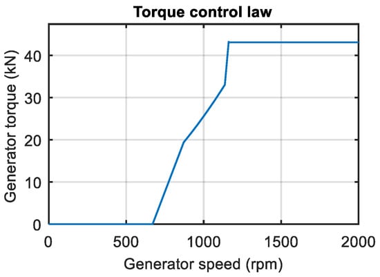
Figure 1.
Theoretical law of torque control based on the MPPT algorithm. A constant wind speed with the value of the nominal wind speed is considered.
It is in the second control system, the traditional pitch controller (Figure 2), that there is room for improving the system performance with the integration of intelligent control techniques, e.g., fuzzy logic control. It is worth noting that the reference control system is based on a Proportional-Integral controller, developed by the NREL, that has dynamic gains that depend on the actual value of the pitch blades. This architecture is usually known as “gain scheduling” and it is based on expert knowledge of the NREL.
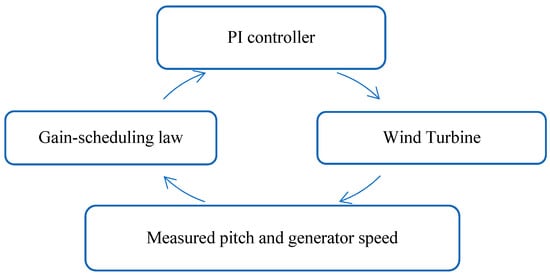
Figure 2.
Simplified diagram for the reference PI controller structure.
Nevertheless, it is mandatory to develop, in advance, a simulation tool and comparison indexes to set a framework that allows for controller comparison, testing, and improvement using common, yet representative, performance metrics.
4. Methodology
The presented methodology has been specifically developed to enable the design, simulation, and comparison of intelligent controllers for a wind turbine placed on a semi-submersible platform. This methodology has already proved to be useful in the improvement of both existing and new controllers.
4.1. Integrated Simulation Tool
A key aspect of the applied methodology is the implementation of a simulation tool integrating all the necessary components. Firstly, measured wind data are sent to the TurbSim 1.21 software (a stochastic, full-field, turbulence simulator) to produce wind profile data in a suitable format for FAST [44]. FAST is a computer-aided engineering (CAE) software provided by the NREL that allows users to simulate the behavior of horizontal axis wind turbines, which can be integrated with MATLAB/Simulink. These wind profiles are one of the most relevant inputs of a FAST simulation model, whose execution produces the outputs of the simulated system (Figure 3 shows the sequence of the stand-alone tools used in this work). The integration of these tools enables the applied methodology, supporting the controllers’ development stage and allowing their simulation to generate the necessary data in order to evaluate the controller using performance indexes according to the OC4 simulation model [45,46].
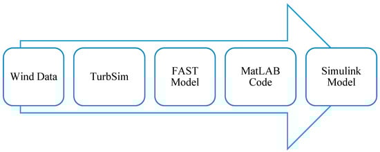
Figure 3.
The integration process of the stand-alone software tools.
4.2. Performance Indexes
The operation of wind turbines on offshore semi-submersible platforms presents significant differences with respect to onshore wind parks and also to offshore wind parks with fixed foundations. Specifically, the displacements of the semi-submersible platform interact with the wind turbine, creating fluctuations that alter the aerodynamic state in which the system operates, with a great impact on electricity production. Moreover, these oscillations may also change the mechanical loads, altering the circumstances for fatigue to appear. In this sense, a controller able to cope with these interactions may significantly improve the profitability of the system, as vibrations play a key role in it [47].
As a key element of the methodology, this work employs three performance indexes already used to evaluate developed controllers for wind turbines in semi-submersible platforms [45]. In contrast with graphical results, e.g., [48,49], the indexes summarize the results using a performance rating, thus making it easier for the reader to understand the contributions of the different controllers and the operation of the system. As [38,43,50] show, two key measurements are the speed tracking error and power generation. Furthermore, [51] remarks on the relevant role of aerodynamics and loads on wind turbines. Nevertheless, there is no consensus about the definition of the performance evaluation indexes, with the mean and standard deviation often being employed. The indexes used in this work record the influence of a controller on the mechanical loads, on the efficiency in electricity generation, and on the behavior of the wind turbine compared with its nominal operation, i.e., the speed reference tracking error. According to this, for the sake of clarity, the definitions of the indexes are given as follows:
- MI (Mechanical loads index). It estimates the impact of the evaluated controller on the lifespan of the platform using the reaction moment, , considering a rigid joint at the base of the turbine:
- GI (Generation index). It provides a measure of the performance on energy harvesting using the difference between the generated power and the nominal power :
- SpI (Speed index). As a performance indicator, this index calculates the difference between the speed of the generator and its nominal value :
All these indexes are calculated as the average of the absolute values for every time step i. Thus, a lower value means a better controller performance.
5. Proposed Fuzzy Logic Controller
The baseline PI acts on the tracking error of the reference for the generator speed, and it presents a gain-scheduling law that depends on the actual value of the collective pitch. The addition of an Anti Wind-Up method (Figure 4) improved this PI performance according to the aforementioned indexes [52]. The original PI is described in detail in [19,45], and the improved PI and its implementation for simulation is presented in [46].
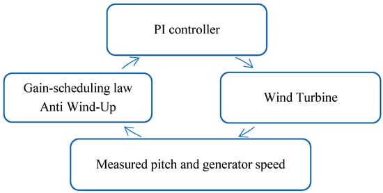
Figure 4.
Simplified diagram for the improved PI scheme.
The main contribution of this work is the description and evaluation of a fuzzy logic controller that adjusts the reference calculated by the improved PI controller. The fuzzy rules were designed according to expert knowledge of the desired behavior of the system. Since the desired behavior could be better described using linguistic variables, a Mamdani-type fuzzy inference was selected. The scheme of the topology of the proposed fuzzy logic controller can be seen in Figure 5.
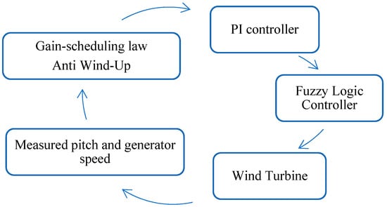
Figure 5.
Simplified diagram for the proposed fuzzy logic controller topology scheme.
As can be seen, the improved PI calculates a pitch reference, which is sent to the fuzzy logic controller. Using it and the generator speed as normalized inputs, this fuzzy logic controller produces a new and adjusted pitch reference for the blades. A common practice is to make the output values fall within the range [0, 1] and to de-normalize it afterward, which, in the scheme, is completed before sending the fuzzy pitch reference to the wind turbine, i.e., the OC4 Deepwind semi-submersible FAST simulation model. Explicitly, the Mamdani-type fuzzy logic controller is composed of:
- Two normalized inputs (generator speed and the pitch reference calculated by the improved PI, Figure 6, Figure 7, Figure 8 and Figure 9) and one normalized output (pitch reference calculated by the fuzzy logic controller, Figure 10 and Figure 11). The membership functions of each of them are shown in Table 2, Table 3 and Table 4.
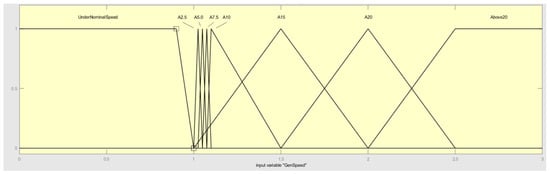 Figure 6. Membership functions of the generator speed input.
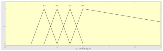 Figure 7. A zoom-in on the range [0.95, 1.25] of the horizontal axis of the membership functions for the generator speed inputs A2.5, A5.0, A7.5, and A10.
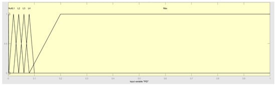 Figure 8. Membership functions of the pitch reference input calculated by the improved PI.
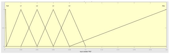 Figure 9. Membership functions of the pitch reference input calculated by the improved PI. Zoom-in on the range [0, 0.20] of the horizontal axis.
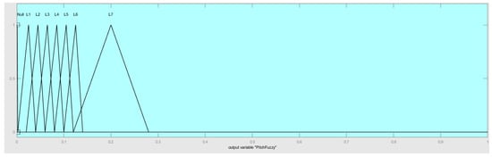 Figure 10. Membership functions of the pitch reference output.
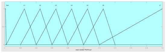 Figure 11. Membership functions of the pitch reference input. Zoom-in on the [0, 0.20] range of the horizontal axis.
Table 2. Input 1 (generator speed) membership functions (MF).
Table 3. Input 2 (improved PI pitch reference) membership functions (MF).
Table 4. Output (fuzzy logic controller pitch reference) membership functions (MF).
Figure 11. Membership functions of the pitch reference input. Zoom-in on the [0, 0.20] range of the horizontal axis.
Table 2. Input 1 (generator speed) membership functions (MF).
Table 3. Input 2 (improved PI pitch reference) membership functions (MF).
Table 4. Output (fuzzy logic controller pitch reference) membership functions (MF). - Forty-eight rules that map the inputs to the output (Table 5). The resulting inputs to output values are shown in Figure 12 and detailed in Figure 13.
Table 5. Rules of the proposed fuzzy logic controller (Fuzzy A).
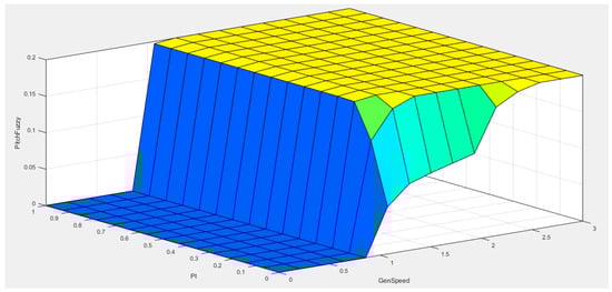 Figure 12. A surface that summarizes the interactions between the rules, inputs, and membership functions to produce the output. The general form representation is due to using a big mesh with low precision.
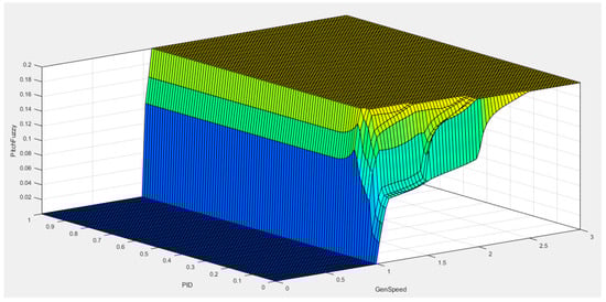 Figure 13. A surface that summarizes the interactions between the rules and membership functions using the output value for each pair of input values. Representation with a small mesh so the details of transitions can be appreciated.
The membership functions for the generator speed input were defined with respect to several relevant speed values above the nominal value, as shown in Figure 6. A normalization with regard to the nominal generator speed is applied. This is reflected in the name of the sets, were A5.0 means a membership function centered on a speed of 5.0% higher than nominal speed, as shown in Figure 7 and summarized in Table 2.
For the improved PI pitch reference input, the behavior of that PI was studied under different operating scenarios, resulting in the division of possible pitch values into some ranges (Figure 8). These ranges are meant to approximate the non-linear relationships that exist between a hypothetical steady wind speed value and the pitch required to achieve a stable response from the wind turbine operating at that wind speed. The names of the membership functions (Figure 9) reflect these ranges as levels (L1, L2, etc.). Table 3 lists these functions.
The expertise of wind turbine designers performed a key role, as the membership functions of the pitch reference output were established according to the pitch references that an expert wind turbine operator would suggest, as shown in Figure 10 and Figure 11.
Thus, the identified drawbacks would be corrected by an expert human operator taking advantage of the potential of the fuzzy logic control technique. Still, this expertise should be embedded into the fuzzy logic controller, hence the importance of the control theory and engineering. Table 4 summarizes the membership functions of the output.
As mentioned before, the integration of the expert knowledge of the wind turbine designer is not trivial. In the case of the proposed fuzzy logic controller, 48 rules were defined that couple expert knowledge with control knowledge. These rules are presented in Table 5.
These rules were stated by assigning different pitch levels to the desired behavior of the wind turbine, as explained in the definition of the fuzzy logic controller inputs. Still, some tuning was required after the initial implementation in order to improve the behavior in turbulent, high-wind speed scenarios using the defined indexes. The methodology presented in Section 3 played a key role in that process.
The surface that maps the inputs to the output values summarizes the behavior of the controller (Figure 12) and was helpful in the process of fine-tuning. It is the result of evaluating each pair of possible inputs, according to the defined membership functions and rules, to produce the output. As the key range of generator speeds that requires a precise control is between the rated generator speed and approximately 15% above it, an additional figure (Figure 13) is presented with a greater detail of the behavior of the controller in this area.
6. Results
The integrated simulation tool has been used to obtain the behavior of the wind turbine on a semi-submersible platform under three different wind scenarios with turbulence class A, the worst case scenario, for each of five different controllers: the baseline NREL PI [19], the improved PI [52], the fuzzy logic controller proposed in this paper (Fuzzy A), a previous fuzzy logic controller presented in [45] (Fuzzy B), and a third fuzzy logic controller (Fuzzy C) depicted in [46,53]. The fuzzy logic controllers are used represent a different control topology, which is summarized in Table 6.
Table 6.
List of controllers compared in this paper. Fuzzy A is proposed in this paper.
Simulation scenarios have been considered for several wind profiles, with an average speed of 13 m/s (Figure 14, Table 7), 15 m/s (Figure 15, Table 8), and 18 m/s (Figure 16, Table 9). These average wind speeds have been selected to characterize the response of the wind turbine when the wind is close to the value that produces the nominal power with a null pitch, i.e., 11.4 m/s, when it is slightly higher than the nominal value, and when it is clearly above.
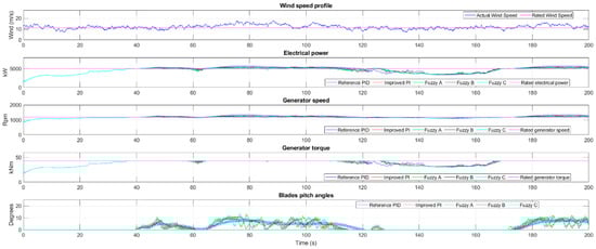
Figure 14.
Comparison of the evaluated controllers for a wind profile of 13 m/s.
Table 7.
Indexes for simulations with wind profile 1 (13 m/s A).
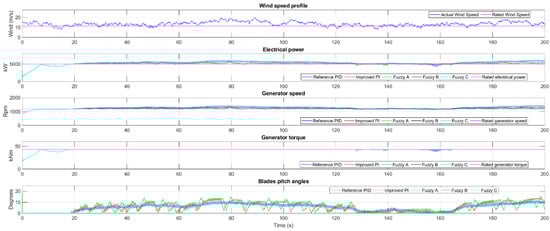
Figure 15.
Comparison of the evaluated controllers for a wind profile of 15 m/s.
Table 8.
Indexes for simulations with wind profile 2 (15 m/s A).
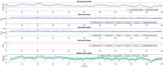
Figure 16.
Comparison of the evaluated controllers for a wind profile of 18 m/s.
Table 9.
Indexes for simulations with wind profile 3 (18 m/s A).
6.1. Wind Profile 13 m/s Turbulence A
The requirements for pitch control are relaxed due to a wind speed lower than the nominal value most of the time, causing the generator speed not to rise above the reference speed frequently. However, there may be some peaks in the wind speed, and the response that a given controller offers might improve the behavior of the system.
The NREL baseline PI can cope with the variations of the wind speed as these are not big enough to lead the generator speed above its nominal value consistently, as seen in Figure 14. The added Anti Wind-Up achieves a more constant pitch reference without losing control capabilities, although there are almost no differences between them. With respect to the PIs, fuzzy logic controller A produces a more stable pitch reference. Similar results are obtained with Fuzzy B and Fuzzy C.
As previously stated, in this scenario, the pitch control has little to no impact on the system behavior as the performance indexes are similar for the five controllers (Table 7). However, two of the fuzzy logic controllers start to exhibit their capabilities to improve the PI results, as the speed index (SpI) is around 10% lower (better) for them.
6.2. Wind Profile 15 m/s Turbulence A
In this second scenario, the requirements of the pitch control are far increased due to a wind speed higher than the nominal value most of the time, causing the generator speed to rise fast above the rated speed if the collective pitch is not properly adjusted. Moreover, the wind speed peaks at 20 m/s in some moments of the simulation and also goes as low as 10 m/s, requiring a controller capable of adjusting the pitch reference regarding this rapid variability. The NREL PI is not fully capable of performing this task (see Figure 15). The improved PI controller, in comparison, improves the behavior as the generator speed is far closer to the rated value than in the NREL PI graphics. Fuzzy A produces better results than the improved PI, as the graphics show a generator speed even closer to the desired value, i.e., the rated value, due to a faster reaction to changes in the wind speed. Similarly, Fuzzy B produces a better performance with respect to the NREL PI. However, it is not as good as the improved PI or even Fuzzy A regarding the behavior of the system. In contrast, Fuzzy B offers better stability than the other two controllers, which sometimes is preferred by wind turbines operators even if the performance is a bit lower. Fuzzy C achieves better results than the improved PI and Fuzzy B.
As pitch control has a bigger impact on performance, the indexes vary broadly for the five controllers (Table 8). In contrast with the previous scenario, this one reflects which controllers adjust the pitch fast enough to allow the system show better behavior.
6.3. Wind Profile 18 m/s Turbulence A
As the wind speed is far above the nominal value all the time, the generator speed rises extremely fast above the rated speed if the pitch is not incremented accordingly, which happens under the baseline PI (see Figure 16). The improved PI is not fully capable of producing a pitch reference as fast as the wind speed changes. However, it can limit the amount the generator speed exceeds the nominal value, which the NREL PI cannot. It is easy to notice the enhancement produced by fuzzy logic controller A with respect to the two PIs. The generator speed is close to the reference, and the speed tracking error is set to a low limit. As in the previous scenario, Fuzzy B offers a poorer performance than Fuzzy A, though its topology provides more flexibility and improves the baseline PI. Finally, Fuzzy C offers a performance as good as Fuzzy A. It is capable of a lower amount of speed tracking error yet is more unstable than Fuzzy A. These differences are due to the fact that the said two controllers were developed with two totally different topologies.
In a high wind speed scenario such as this one, the pitch control has an impact on performance. Because of this, the indexes values (Table 9) are more widespread than in the previous study cases. In the case of the previous scenario, controllers that adapt the pitch rapidly and accurately score lower (better) values of the indexes.
7. Discussion
In addition to the curves and the performance indexes for each scenario, an aggregated table with all the index values for all the scenarios enables further comprehension of the controllers’ performance. For the sake of clarity, Table 6 is replicated as Table 10, recalling the different controllers evaluated, while Table 11, Table 12 and Table 13 present the indexes for each one of these controllers.
Table 10.
Controllers evaluated. Fuzzy A is proposed in this paper.
Table 11.
Mechanical loads index, MI (MN·m).
Table 12.
Generation Index, GI (MW).
Table 13.
Speed Index, SpI (rpm).
Firstly, the evaluated controllers score similarly in the 13 m/s with turbulence A simulation scenario due to the little pitch control required, but as wind speed increases above the nominal value, i.e., 11.4 m/s, the performance of the controllers begins to vary, hence the behavior of the system. Finally, when the wind speed rises further, these differences among the controllers are even bigger.
As the performance indexes summarize, the mechanical loads suffer the smallest variations among the indexes. Still, Fuzzy A and Fuzzy C produce noticeable improvements at around a 10% lower value in the 18 m/s scenario. Wind turbine operators give high importance to structural operation parameters, and, as stated before, the literature has analyzed the effects of loads on the lifespan of wind turbines and the great impact of them on the profitability of the investment [54].
In contrast, both the energy produced and the tracking of the speed reference show great differences for each controller. These two indexes indicate that Fuzzy A controller achieves lower, and hence better, scores in the overall comparison.
This fuzzy logic controller is based both on the reliability of a PI plus the flexibility of the fuzzy logic control implementing the desired behavior from the point of view of a turbine operator. However, Fuzzy C achieves better scores than Fuzzy A in some scenarios, although its potential for escalation is lower due to the differences in their topologies. Furthermore, these two controllers are the result of the application of all the knowledge acquired during the development of previous controllers for each of the topologies. Specifically, topologies or techniques that achieved worse scores, such as Fuzzy B or the improved PI, and the previous versions of A and C allowed a better understanding of the problem. However, it should be noted that Fuzzy B acts as a single controller of the system, substituting the PI, which is remarkable because the other four controllers involve a PI in some manner. Thus, this controller could be a candidate to substitute the now standard PI controller. This fuzzy controller features the most stable pitch control behavior but at the cost of worse performance, so it is not attractive for an actual deployment in a commercial turbine. On the other hand, the improved PI enhances the baseline PI by considering the dynamic behavior when the wind speed varies rapidly, i.e., a turbulence scenario. However, as it is based only on the speed tracking error, there is lack of faster adjustments when turbulence occurs, which is completed by fuzzy controllers.
As previously stated, fuzzy controllers A and C merge the fuzzy logic control and the improved PI, partially removing the flaws of both and creating synergies that allow for further improvement in the behavior of the controlled system. Both fuzzy controllers keep a PI in the architecture, which can help their adoption in commercial systems. The performances of Fuzzy A and C are improved with respect to the rest of the controllers included in the comparison. Additionally, the proposed fuzzy controller can be enhanced incrementally by the turbine operator by adding new rules or changing its topology without modifying the improved PI.
8. Conclusions
Controller design plays a key role in obtaining a good performance of wind turbines, particularly in offshore systems where the oscillatory motion of the platform interacts with the wind turbine and has an effect on the performance in energy generation as well as on the expected lifespan of the system.
In this context, this work presents a fuzzy logic controller designed to take into account these effects, enhancing the performance of the system regarding the mechanical loads in the platform, generation of electric energy, and tracking of the speed reference, as stated by the values of a set of performance indexes and the results obtained with an integrated simulation tool, which comprise the methodology employed for comparison of the controllers. This methodology has been used to validate intelligent controllers, proving that fuzzy logic control is a promising alternative to improve the performance of wind turbines in semi-submersible offshore platforms.
In particular, the methodology has been applied to the reference PI controller, an improved version of this PI, a stand-alone fuzzy logic controller, a fuzzy logic controller that adjust the gains of the PI, and the fuzzy logic controller proposed in this work. The proposed fuzzy logic controller achieved the best results in the comparison, proving that the combination of intelligent control and traditional control techniques can result in a better controller with fewer drawbacks. In addition, the comparison shows the potential that intelligent control has in the field of wind turbine control in offshore scenarios, as the three fuzzy logic topologies evaluated performed better than the reference PI for each of the three simulation scenarios, while having far better escalation possibilities.
Future lines of work include the development of alternative intelligent controllers and the escalation of the evaluated ones to consider effects such as wave energy converters on the platform or the grid status. In particular, the proposed fuzzy logic controller is based on the topology with the best potential to escalate among the three evaluated, as these effects may be integrated in the actual set of inputs, output, and rule definitions without modifying or erasing the PI controller. An interesting future line is the integration and evaluation of techniques that allow for more degrees of freedom for the designer, such as type-2 fuzzy systems, FOPID, or a combination of both.
Author Contributions
Conceptualization, P.Z., J.J.F.-L., J.F.-Q., P.M.M.R. and A.G.-C.; methodology, P.Z., J.J.F.-L., P.M.M.R. and J.F.-Q.; software, P.Z.; validation, P.Z. and J.F.-Q.; formal analysis, P.Z. and J.F.-Q.; investigation, P.Z.; resources, P.M.M.R. and J.F.-Q.; data curation, P.Z.; writing—original draft preparation, P.Z.; writing—review and editing, P.Z., J.J.F.-L., P.M.M.R., J.F.-Q. and A.G.-C.; visualization, P.Z.; supervision, J.J.F.-L. and P.M.M.R.; project administration, J.J.F.-L. and P.M.M.R.; funding acquisition, P.M.M.R. and J.J.F.-L. All authors have read and agreed to the published version of the manuscript.
Funding
This work was partially supported by the Ministry of Economy and Competitiveness (Government of Spain) and European Union (RTC-2016-5712-3); by the European Union, CDTI (Spain) and BEISS (UK) through the call H2020 ERA-NET DEMOWIND (WIP10+ project); by the Regional Government of Andalusia and European Union (UMA-CEIATECH-18); and finally, by partial funding for open access charge from the Universidad de Málaga.
Institutional Review Board Statement
Not applicable.
Informed Consent Statement
Not applicable.
Data Availability Statement
Not applicable.
Conflicts of Interest
EnerOcean SL, as the owner of W2Power technology, is the main promoter of the development and validation of the control techniques presented in the article. These techniques could be implemented within the framework of the floating wind industry on both W2Power and other devices. Therefore, the authors J.F.-Q. and P.M.M.R. have the ultimate goal of commercially exploiting the control techniques and development methodologies exposed. The authors working at Universidad de Málaga, P.Z., J.J.F.-L., and A.G.-C., declare that they have no known competing financial interest or personal relationships that could have appeared to influence the work reported in this paper. Finally, the funders had no role in the design of the study, in the collection, analyses, or interpretation of data, in the writing of the manuscript, or in the decision to publish the results.
References
- Sahin, A.D. Progress and Recent Trends in Wind Energy. Prog. Energy Combust. Sci. 2004, 30, 501–543. [Google Scholar] [CrossRef]
- Leung, D.Y.C.; Yang, Y. Wind Energy Development and Its Environmental Impact: A Review. Renew. Sustain. Energy Rev. 2012, 16, 1031–1039. [Google Scholar] [CrossRef]
- Ciuriuc, A.; Rapha, J.I.; Guanche, R.; Domínguez-García, J.L. Digital Tools for Floating Offshore Wind Turbines (FOWT): A State of the Art. Energy Rep. 2022, 8, 1207–1228. [Google Scholar] [CrossRef]
- Castro-Santos, L.; Filgueira-Vizoso, A.; Carral-Couce, L.; Formoso, J.Á.F. Economic Feasibility of Floating Offshore Wind Farms. Energy 2016, 112, 868–882. [Google Scholar] [CrossRef]
- Caglayan, D.G.; Ryberg, D.S.; Heinrichs, H.; Linßen, J.; Stolten, D.; Robinius, M. The Techno-Economic Potential of Offshore Wind Energy with Optimized Future Turbine Designs in Europe. Appl. Energy 2019, 255, 113794. [Google Scholar] [CrossRef]
- Sahu, B.K. Wind Energy Developments and Policies in China: A Short Review. Renew. Sustain. Energy Rev. 2018, 81, 1393–1405. [Google Scholar] [CrossRef]
- The International Renewable Energy Agency. Renewable Energy Statistics 2019; The International Renewable Energy Agency: Abu Dhabi, United Arab Emirates, 2019. [Google Scholar]
- Red Eléctrica de España Informe Del Sistema Eléctrico Español 2019. 2020. Available online: https://www.ree.es/es/datos/publicaciones/informe-anual-sistema/informe-del-sistema-electrico-espanol-2019 (accessed on 15 January 2023).
- Ren, Z.; Verma, A.S.; Li, Y.; Teuwen, J.J.E.; Jiang, Z. Offshore Wind Turbine Operations and Maintenance: A State-of-the-Art Review. Renew. Sustain. Energy Rev. 2021, 144, 110886. [Google Scholar] [CrossRef]
- Sawant, M.; Thakare, S.; Rao, A.P.; Feijóo-Lorenzo, A.E.; Bokde, N.D. A Review on State-of-the-Art Reviews in Wind-Turbine- and Wind-Farm-Related Topics. Energies 2021, 14, 2041. [Google Scholar] [CrossRef]
- Baloch, M.H.; Wang, J.; Kaloi, G.S. A Review of the State of the Art Control Techniques for Wind Energy Conversion System. Int. J. Renew. Energy Res. 2016, 6, 1276–1295. [Google Scholar]
- Kusiak, A.; Zhang, Z.; Verma, A. Prediction, Operations, and Condition Monitoring in Wind Energy. Energy 2013, 60, 1–12. [Google Scholar] [CrossRef]
- Abdullah, M.A.; Yatim, A.H.M.; Tan, C.W.; Saidur, R. A Review of Maximum Power Point Tracking Algorithms for Wind Energy Systems. Renew. Sustain. Energy Rev. 2012, 16, 3220–3227. [Google Scholar] [CrossRef]
- García-Sanz, M.; Houpis, C.H. Wind Energy Systems: Control Engineering Design; CRC Press, Taylor & Francis: Boca Raton, FL, USA, 2012; ISBN 9781439821794. [Google Scholar]
- Tomás-Rodríguez, M.; Santos, M. Modelling and Control of Floating Offshore Wind Turbines. RIAI-Rev. Iberoam. Autom. E Inform. Ind. 2019, 16, 381–390. [Google Scholar] [CrossRef]
- Senjyu, T.; Sakamoto, R.; Urasaki, N.; Funabashi, T.; Fujita, H.; Sekine, H. Output Power Leveling of Wind Turbine Generator for All Operating Regions by Pitch Angle Control. IEEE Trans. Energy Convers. 2006, 21, 467–475. [Google Scholar] [CrossRef]
- Kim, Y.S.; Chung, I.Y.; Moon, S. Il Tuning of the PI Controller Parameters of a PMSG Wind Turbine to Improve Control Performance under Various Wind Speeds. Energies 2015, 8, 1406–1425. [Google Scholar] [CrossRef]
- Maureen Hand, M.; Balas, M.J. Systematic Approach for PID Controller Design for Pitchregulated, Variable-Speed Wind Turbines. ASME Wind Energy Symp. 1998, 84–94. [Google Scholar] [CrossRef]
- Jonkman, J.; Butterfield, S.; Musial, W.; Scott, G. Definition of a 5-MW Reference Wind Turbine for Offshore System Development; Technical Report; U.S. Department of Energy: Washington, DC, USA, 2009. [CrossRef]
- Gambier, A.; Behera, A. Integrated Pitch Control System Design of a Wind Turbine by Using Multiobjective Optimization. IFAC-Pap. 2018, 51, 239–244. [Google Scholar] [CrossRef]
- Gambier, A.; Nazaruddin, Y.Y. Collective Pitch Control with Active Tower Damping of a Wind Turbine by Using a Nonlinear PID Approach. IFAC-Pap. 2018, 51, 238–243. [Google Scholar] [CrossRef]
- Jain, A.; Schildbach, G.; Fagiano, L.; Morari, M. On the Design and Tuning of Linear Model Predictive Control for Wind Turbines. Renew. Energy 2015, 80, 664–673. [Google Scholar] [CrossRef]
- Song, D.; Yang, J.; Dong, M.; Joo, Y.H. Model Predictive Control with Finite Control Set for Variable-Speed Wind Turbines. Energy 2017, 126, 564–572. [Google Scholar] [CrossRef]
- Vinagre, B.M.; Monje, C.A. Introducción Al Control Fraccionario | Revista Iberoamericana de Automática e Informática Industrial. Rev. Iberoam. Automática Inf. Ind. 2009, 3, 5–23. [Google Scholar]
- Paducel, I.; Safirescu, C.O.; Dulf, E.H. Fractional Order Controller Design for Wind Turbines. Appl. Sci. 2022, 12, 8400. [Google Scholar] [CrossRef]
- Lei, Z.; Wang, X.; Zhou, S.; Wang, Z.; Wang, T.; Yang, Y. A Review of Research Status and Scientific Problems of Floating Offshore Wind Turbines. Energy Eng. 2021, 119, 123–143. [Google Scholar] [CrossRef]
- Truong, H.V.A.; Dang, T.D.; Vo, C.P.; Ahn, K.K. Active Control Strategies for System Enhancement and Load Mitigation of Floating Offshore Wind Turbines: A Review. Renew. Sustain. Energy Rev. 2022, 170, 112958. [Google Scholar] [CrossRef]
- De Souza, C.E.S.; Bachynski-Polić, E.E. Design, Structural Modeling, Control, and Performance of 20 MW Spar Floating Wind Turbines. Mar. Struct. 2022, 84, 103182. [Google Scholar] [CrossRef]
- Basbas, H.; Liu, Y.C.; Laghrouche, S.; Hilairet, M.; Plestan, F. Review on Floating Offshore Wind Turbine Models for Nonlinear Control Design. Energies 2022, 15, 5477. [Google Scholar] [CrossRef]
- Homer, J.R.; Nagamune, R. Physics-Based 3-D Control-Oriented Modeling of Floating Wind Turbines. IEEE Trans. Control Syst. Technol. 2018, 26, 14–26. [Google Scholar] [CrossRef]
- Wakui, T.; Yoshimura, M.; Yokoyama, R. Multiple-Feedback Control of Power Output and Platform Pitching Motion for a Floating Offshore Wind Turbine-Generator System. Energy 2017, 141, 563–578. [Google Scholar] [CrossRef]
- Bouregba, H.; Hachemi, M.; Bey, M.; Hamidat, A. Stability Analysis of the Pitch Angle Control of Large Wind Turbines Using Different Controller Strategies. Adv. Mech. Eng. 2022, 14, 16878132221139926. [Google Scholar] [CrossRef]
- Sierra-Garcia, J.E.; Santos, M. Deep Learning and Fuzzy Logic to Implement a Hybrid Wind Turbine Pitch Control. Neural Comput. Appl. 2022, 34, 10503–10517. [Google Scholar] [CrossRef]
- Sierra-García, J.E.; Santos, M. Neural Networks and Reinforcement Learning in Wind Turbine Control. RIAI-Rev. Iberoam. Autom. E Inform. Ind. 2021, 18, 327–335. [Google Scholar] [CrossRef]
- Sacie, M.; López, R.; Santos, M. Exploratory Data Analysis of Wind and Waves for Floating Wind Turbines in Santa María, California. In Lecture Notes in Computer Science; Springer Science and Business Media: Berlin/Heidelberg, Germany, 2020; Volume 12490, pp. 252–259. [Google Scholar]
- Santos Peñas, M.; Miranda Suescun, E. Aplicación de La Lógica Difusa En El Ámbito de Las Energías Renovables. Elementos 2012, 2, 101–114. [Google Scholar] [CrossRef]
- Simoes, M.G.; Bose, B.K.; Spiegel, R.J. Fuzzy Logic Based Intelligent Control of a Variable Speed Cage Machine Wind Generation System. IEEE Trans. Power Electron. 1997, 12, 87–95. [Google Scholar] [CrossRef]
- Lasheen, A.; Elshafei, A.L. Wind-Turbine Collective-Pitch Control via a Fuzzy Predictive Algorithm. Renew. Energy 2016, 87, 298–306. [Google Scholar] [CrossRef]
- Firouzi, B.; Alattas, K.A.; Bakouri, M.; Alanazi, A.K.; Mohammadzadeh, A.; Mobayen, S.; Fekih, A. A Type-2 Fuzzy Controller for Floating Tension-Leg Platforms in Wind Turbines. Energies 2022, 15, 1705. [Google Scholar] [CrossRef]
- Chavero-Navarrete, E.; Trejo-Perea, M.; Jáuregui-Correa, J.C.; Carrillo-Serrano, R.V.; Ríos-Moreno, J.G. Expert Control Systems for Maximum Power Point Tracking in a Wind Turbine with PMSG: State of the Art. Appl. Sci. 2019, 9, 2469. [Google Scholar] [CrossRef]
- Larsen, T.J.; Yde, A.; Verelst, D.R.; Pedersen, M.M.; Hansen, A.M.; Hansen, H.F. IEA Annex 30 Offshore Code Collaboration Continued (OC4) Phase I+II. Final Report of the Contributions from EUDP 64010-0071. DTU Wind Energy 2014, 1, 0240. [Google Scholar]
- Robertson, A.; Jonkman, J.; Masciola, M.; Song, H.; Goupee, A.; Coulling, A.; Luan, C. Definition of the Semisubmersible Floating System for Phase II of OC4; National Renewable Energy Lab. (NREL): Golden, CO, USA, 2014.
- Lin, W.-M.; Hong, C.-M. Intelligent Approach to Maximum Power Point Tracking Control Strategy for Variable-Speed Wind Turbine Generation System. Energy 2010, 35, 2440–2447. [Google Scholar] [CrossRef]
- Jonkman, B.J.; Jonkman, J.M. FAST v8.16.00a-Bjj User’s Guide. Natl. Renew. Energy Lab. 2016, 58, 1355. [Google Scholar]
- Mayorga Rubio, P.; Fernández Quijano, J.; Zambrana López, P.; Fernández Lozano, J.J.; García Cerezo, A.; Ortega Casanova, J. Control Inteligente Para Mejorar El Rendimiento de Una Plataforma Semisumergible Híbrida Con Aerogenerador y Convertidores de Oleaje: Sistema de Control Borroso Para La Turbina. Rev. Iberoam. Automática Inf. Ind. 2019, 16, 480. [Google Scholar] [CrossRef]
- Zambrana, P.; Fernandez-Quijano, J.; Fernandez-Lozano, J.J.; Rubio, P.M.M.; Garcia-Cerezo, A.J.; Fernandez-Quijano, J.; Fernandez-Lozano, J.J.; Rubio, P.M.M.; Garcia-Cerezo, A.J. Improving the Performance of Controllers for Wind Turbines on Semi-Submersible Offshore Platforms: Fuzzy Supervisor Control. Energies 2021, 14, 6222. [Google Scholar] [CrossRef]
- Martynowicz, P. Real-Time Implementation of Nonlinear Optimal-Based Vibration Control for a Wind Turbine Model. J. Low Freq. Noise Vib. Act. Control 2018, 38, 1635–1650. [Google Scholar] [CrossRef]
- Moodi, H.; Bustan, D. Wind Turbine Control Using T-S Systems with Nonlinear Consequent Parts. Energy 2019, 172, 922–931. [Google Scholar] [CrossRef]
- Belmokhtar, K.; Doumbia, M.L.; Agbossou, K. Novel Fuzzy Logic Based Sensorless Maximum Power Point Tracking Strategy for Wind Turbine Systems Driven DFIG (Doubly-Fed Induction Generator). Energy 2014, 76, 679–693. [Google Scholar] [CrossRef]
- Koutroulis, E.; Kalaitzakis, K. Design of a Maximum Power Tracking System for Wind-Energy-Conversion Applications. IEEE Trans. Ind. Electron. 2006, 53, 486–494. [Google Scholar] [CrossRef]
- Shen, X.; Zhu, X.; Du, Z. Wind Turbine Aerodynamics and Loads Control in Wind Shear Flow. Energy 2011, 36, 1424–1434. [Google Scholar] [CrossRef]
- Zambrana-Lopez, P.; Fernandez-Lozano, J.J.; Fernandez-Quijano, J.; Mayorga-Rubio, P.M.; Garcia-Cerezo, A.J. A Methodology for Improving the PI Controller of a Wind Turbine on a Semi-Submersible Offshore Platform: Development and Evaluation of an Anti Windup Algorithm. In Proceedings of the 10th EUROSIM2019 Congress, Logroño, Spain, 1–5 July 2019; pp. 1–12. [Google Scholar]
- Zambrana-Lopez, P.; Fernández-Quijano, J.; Fernandez-Lozano, J.J.; Garcia-Cerezo, A.; Mayorga Rubio, P.M. Fuzzy Logic Tuning of a PI Controller to Improve the Performance of a Wind Turbine on a Semi-Submersible Platform under Different Wind Scenarios. IFAC-Pap. 2020, 53, 12364–12371. [Google Scholar] [CrossRef]
- Bošnjaković, M.; Katinić, M.; Santa, R.; Marić, D. Wind Turbine Technology Trends. Appl. Sci. 2022, 12, 8653. [Google Scholar] [CrossRef]


Disclaimer/Publisher’s Note: The statements, opinions and data contained in all publications are solely those of the individual author(s) and contributor(s) and not of MDPI and/or the editor(s). MDPI and/or the editor(s) disclaim responsibility for any injury to people or property resulting from any ideas, methods, instructions or products referred to in the content. |
© 2023 by the authors. Licensee MDPI, Basel, Switzerland. This article is an open access article distributed under the terms and conditions of the Creative Commons Attribution (CC BY) license (https://creativecommons.org/licenses/by/4.0/).