Article

Design of a Compact Planar Magnetic Levitation System with Wrench–Current Decoupling Enhancement

by
Chanuphon Trakarnchaiyo
,
Yang Wang
and
Mir Behrad Khamesee
*
Department of Mechanical and Mechatronics Engineering, University of Waterloo, Waterloo, ON N2L 3G1, Canada
*
Author to whom correspondence should be addressed.
Appl. Sci. 2023, 13(4), 2370; https://doi.org/10.3390/app13042370
Submission received: 23 January 2023 / Revised: 7 February 2023 / Accepted: 10 February 2023 / Published: 12 February 2023
(This article belongs to the Special Issue Smart Machines and Intelligent Manufacturing)

Abstract

:
Magnetic levitation technology has promising applications in modern manufacturing, especially for fine-motion stage and long-range omnidirectional planar motors. This paper presents the development of a compact planar maglev prototype with the potential to achieve both applications to increase flexibility for the manufacturing system. The planar stator is designed by using optimized square coils arranged in the zigzag configuration, which provides a better uniform magnetic flux density compared with another configuration. The stator is a compact and portable module with built-in current amplifier units. The single-disc magnet mover is deployed with five controllable degrees of freedom. The cross-coupling effect is decoupled by a precomputed Lorentz force based wrench—current transformation matrix stored in the lookup table. A 2-D linear interpolation is implemented to enhance decoupling effectiveness which is offered via discrete lookup data. Experiments with motion-tracking cameras and a basic controller demonstrate the results of fine step motion of 10 and 20 µm and rotation steps of 0.5 and 1.0 mrad. The potential for multidirectional material handling is represented by a total horizontal translation range of 20 mm by 20 mm with a maximum air gap of 26 mm and a total rotation range of 20 degrees for both roll and pitch.

1. Introduction

Nowadays, magnetic levitation or maglev technology is applied in various fields from macro- to microlevel applications. Maglev technology utilizes the interaction between magnets and/or electromagnets to levitate a magnetized object without contact. By manipulating the actuator outputs, attractive or repulsive forces are generated on the object to control the motion. With its advantages of low friction and contactless motion, maglev can provide high-speed and dustless motion. One of the well-known applications is high-speed transportation such as maglev trains [1] and hyperloop [2]. Meanwhile, various robotic applications using maglev technology can be found in [3]. The maglev system can perform delicate tasks in micromanipulation [4,5,6] and haptics [7]. Moreover, it can also be applied for modern industrial applications, for example, metal melting [8], magnetic bearing [9] for high-speed electrical machines, and metal additive manufacturing [10].
Another industrial application of maglev is for manufacturing systems. Since the suspended object can be controlled for multiple degree-of-freedom (DOF) motion, the maglev system can improve the flexibility of the machining or material handling tasks in the production line. For these tasks, the repulsive-type planar maglev system, which has the mover levitated on top of the stator, is more suitable than the attractive-type system because it enables the system to work with other automation systems such as CNC machines and industrial robots. For the planar maglev system structure, there are two types of movers, namely, moving coils and moving magnets, which work with magnet stators and electromagnet stators, respectively. Even though some research works use moving coil mover [11,12]; this type of mover is not popular because it must be equipped with or wired to the power source to energize moving coils.
By using several combinations of magnet movers and electromagnet stators, the previous research works mainly aimed to develop maglev systems for high-precision and/or long-range motion. For high-precision motion, the system structures are usually designed with multiple sets of coil stators and moving magnet arrays. The mover is controlled to have a fine motion with micro- or nanolevel precision and relatively small errors. An early high-precision maglev stage was developed for photolithography [13] which had a translation range of 50 mm by 50 mm with a motion step size of 50 nm. Subsequent designs of high-precision maglev stages utilized multiple sets of 1-D Halbach arrays with long rectangular coils [14] with 100 mm motion stroke and 20 nm step motion, or square coil arrays [15] which presented the high-precision steps of 1 μ m and its RMSE of 0.58 μ m. The alternative stage design had multiple single-axis maglev actuators made of a cylindrical magnet and a cylindrical coil for vertical and horizontal motion control [16]. The design of a dual-stage mover for fine motion can be found in [17]. Not only precision linear stages, but the design of a circular Halbach array mover and electromagnet stator arranged in a circle can also achieve high-precision rotary table [18,19]. From the review, the Halbach array mover is widely used because it has the advantage of focusing a strong magnetic field on one side. Most of the proposed systems were invented for short- or medium-stroke motion with a small levitation gap below 10 mm and small rotation ranges. Moreover, most of the structures were designed as multiactuator stages. It is difficult to extend this structure for long-range motion even though some works have long motion strokes.
For long-range motion, the stator is designed to be planar and expandable since the motion range of the mover is limited by the stator area. A topology comparison of four coil arrays in [20] indicated that the rectangular coil array in a herringbone pattern provided low-power dissipation and small force/torque ripples on the 2-D Halbach array mover. The modular stator of multilayer copper conductors in [21] could be expanded easily while achieving precision motion with microlevel motion error. However, the levitation gap was still small. The long-range translation with a large levitation gap can be realized using disc magnets and a cylindrical coil array. A single disc magnet can be controlled for five-DOF motion only [22] because of its symmetry around the vertical axis. In [23], a two-disc-magnet mover could achieve six-DOF motion with an air gap of 25 mm. Then, the unlimited yaw rotation using six disc magnets mounted on a ball-shaped mover was demonstrated in [24]. Nevertheless, the levitation error was large due to the slow sensing and control frequency.
In real-time motion control of the planar maglev system, the cross-coupling effect in this overactuated system is usually decoupled by a wrench–current transformation matrix. The force and torque components in this matrix are based on the Lorentz force law which requires the computations of (1) magnetic flux density and (2) forces and torques from the volume integral. For the magnetic flux density, the magnetic node approach [25] is used for the rectangular magnet but is also applicable for the cylindrical magnet. The magnetic flux density of the Halbach array can be rapidly estimated by the order-reduction harmonic model [26,27]. Next, the volume integral can be solved by numerical methods. The Gaussian quadrature technique which can transform the integral into the summation was implemented on an FPGA for parallel computing [28] and used for real-time decoupling for the maglev rotary table in [29].
Alternatively, selecting the nearest wrench–current transformation matrix from a lookup table, which stores precomputed transformation matrices in a specific range, was used for disc-magnet mover in [22,30]. However, the lookup table approach has a problem with its discrete data. The effectiveness of decoupling at the no-data locations deteriorates because the transformation matrix is acquired from the nearest data. Therefore, the decoupling enhancement using estimation techniques for the transformation matrix at the locations without lookup data can improve the levitation performance. The multidimensional linear interpolation was implemented in [23,24] to improve the accuracy in long-range translation and rotation whereas the performance of the fine motion was not examined. This paper presents a novel design of a compact planar maglev system, which is capable of expanding for large-area omnidirectional levitation while performing a high-precision motion, to be applicable to modern manufacturing systems. The main objectives of this work are described as follows:
  • The compact and portable design of a five-DOF repulsive planar maglev prototype using an array of square coils with a single disc magnet mover: The system is intended to perform as a fine motion stage for a precision machining workstation. Meanwhile, the design is capable of expanding the planar stator as a module for long-range levitation.
  • Wrench–current decoupling enhancement using multidimensional interpolation for the fine motion: An implementation of a linear interpolation method can improve the levitation performance at the mover pose without data in the lookup table. This method is feasible to deploy on a control system with limited computational resources.
The rest of this paper is organized as follows: Section 2 details the compact planar maglev system design. The implementation of the working principle from Section 3 and the wrench–current decoupling enhancement using a linear multidimensional interpolation for the real-time control system are described in Section 4. The results of levitation experiments are presented in Section 5. The discussions of this work are given in Section 6 and a conclusion is provided in Section 7.

2. System Design Procedure

The main components of the planar maglev system in this work include an electromagnet stator and a permanent magnet (PM) mover. This section provides the details of the planar maglev system design starting from the electromagnet, stator array configuration, and compact system structure. Subsequently, the details of a single-disc magnet mover are described.

2.1. Electromagnet Design

A comparison between square and cylindrical coils of similar size in [30] indicated that an average magnetic flux density generated by an array of square coils was stronger than that of cylindrical coils. Thus, a square coil is preferable.
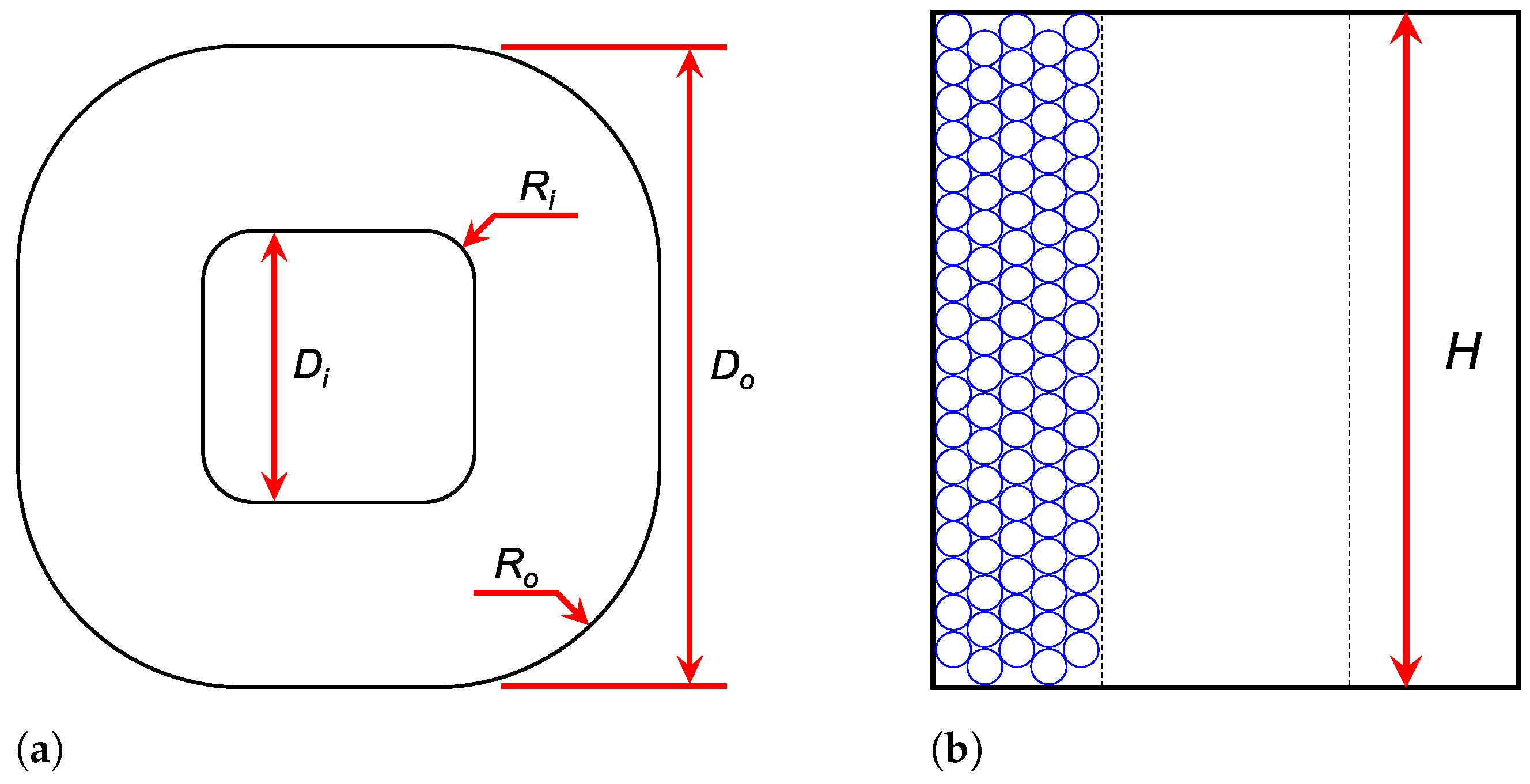
Figure 1 presents the top and side views of the round-corner square coil with inner radius R i and outer radius R o . There were three key dimensions to be designed in this work, the inner width D i , the outer width D o , and the height H. The coil was designed with the objective of this research to propose a compact and portable design of the planar maglev system. First, the inner width was obtained from the width of the coil bobbin spool. The bobbin spool was made of a 31.75 mm (1-1/4-inch) aluminum square tube welded on a 76.2 mm (3-inch) aluminum square base flange. The advantages of using the hollow aluminum bobbin are a good machinability, an efficient heat dissipation from the coil, and a slight influence on the magnetic field generated by the coil.
Next, the outer width was determined by the thickness of the winding. The winding was assumed to be evenly distributed with the orthocyclic winding pattern as shown in Figure 1b, which ideally provides an optimal fill factor of 90.7 % [31]. In this work, an insulated magnet wire gauge of 16 AWG with a diameter d of 1.31 mm was used to make the coils with a maximum current of 7 A. The winding thickness can be calculated from the magnet wire diameter and the number of radial layers but must not exceed the width of the bobbin base flange. By considering a 10 % tolerance from the material dimension and winding process, the number of radial layers of 16 was selected. As a result, the total outer width of the coil was approximately 75 mm.
Since the inner and outer widths of the coil were decided, the height of the coil was designed to achieve an optimal energy efficiency and levitation effort. In terms of energy use, the Fabry factor was used in this work. This factor considers the coil geometry to evaluate the efficiency in generating a magnetic field. Even though the factor was derived from the cylindrical coil, it was adopted in this initial design since the square coil in this work had a large corner radius which resembled that of a cylindrical coil. The Fabry factor G of the uniform-current-density coil was expressed in [32] as
G ( α , β ) = 1 5 2 π β α 2 1 ln α + α 2 + β 2 1 + 1 + β 2 ,
where α = D o / D i and β = H / D i . From the designed outer and inner widths, the ratio of the coil’s outer-inner width was α = 2.36 . The remaining variable β depended on the height of the coil. With the designed α value, the best G value this design could achieve was 0.175, where β = 1.59 . Therefore, the optimal coil height from the Fabry factor was 50.48 mm, which was equivalent to 35 vertical winding turns or 50.435 mm.
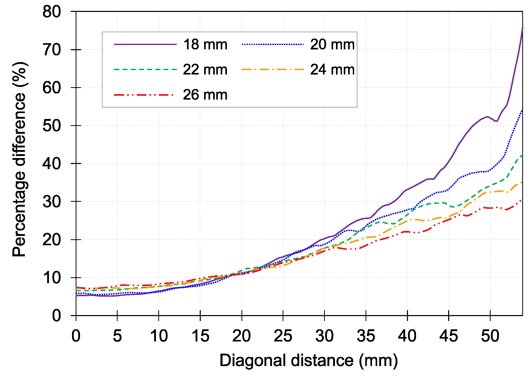
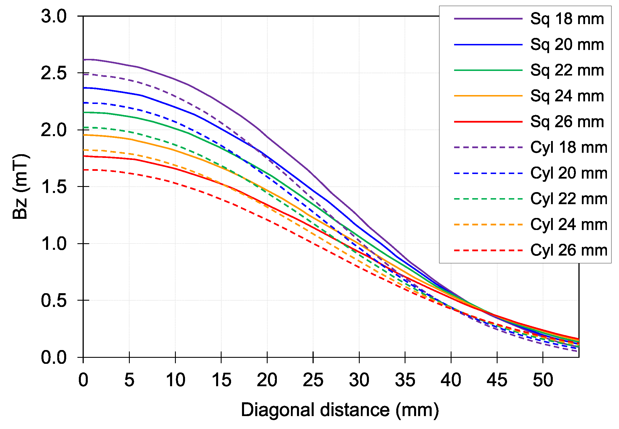
Simulations of a square and a cylindrical coil with parameters in Table 1 were conducted using finite element analysis software ANSYS Maxwell. Both coils were comparable in size with the designed inner-outer widths and optimal height from the Fabry factor. The comparison of the z-component of the magnetic flux density B z between the two coils is shown in Figure 2. The magnetic flux density is observed along the diagonal distance from center to corner at different levels from 18 mm to 26 mm above the coil top surface. The square coil could generate a stronger magnetic flux density than the cylindrical coil, especially at the corner, with higher percentage differences as shown in Figure 3. With an average difference of 18 % , the height of the square coil was determined to attain at least 82 % of the best achievable G value ( G 0.144 ). Accordingly, the range of β was 0.60 β 4.22, and the range of the coil height was 19.05 mm H 133.98 mm.
Another factor to be considered for the coil height optimization is the levitation effort. The vertical force was mainly considered in this design. To consider the Fabry factor and the vertical force together, the maximum height must be determined since the force continues to increase with the increment of the coil height or the number of vertical winding turns. With the optimal height and the range of the coil height from the previous step, the coil height was preferred to be higher than the optimal height to provide more force. Therefore, the range of coil height was from 50.48 mm to 133.98 mm. The range of the number of vertical winding turns was from 35 turns to 90 turns.
The parametric simulation of the force between a square coil and a single disc magnet was conducted in ANSYS Maxwell with the parameters in Table 2. The simulation model consisted of a disc magnet grade N50, a 101.60 mm (4-inch) diameter × 12.70 mm (1/2-inch) thickness, suspended with a 20 mm gap above the center of the square coil. The coil had inner and outer widths as designed. The coil height was a function of the number of vertical winding turns N v e r t . The coil was supplied with a current of 1 A. Ideally, only the z-component of the force on the magnet can be observed whereas other force components are zero.
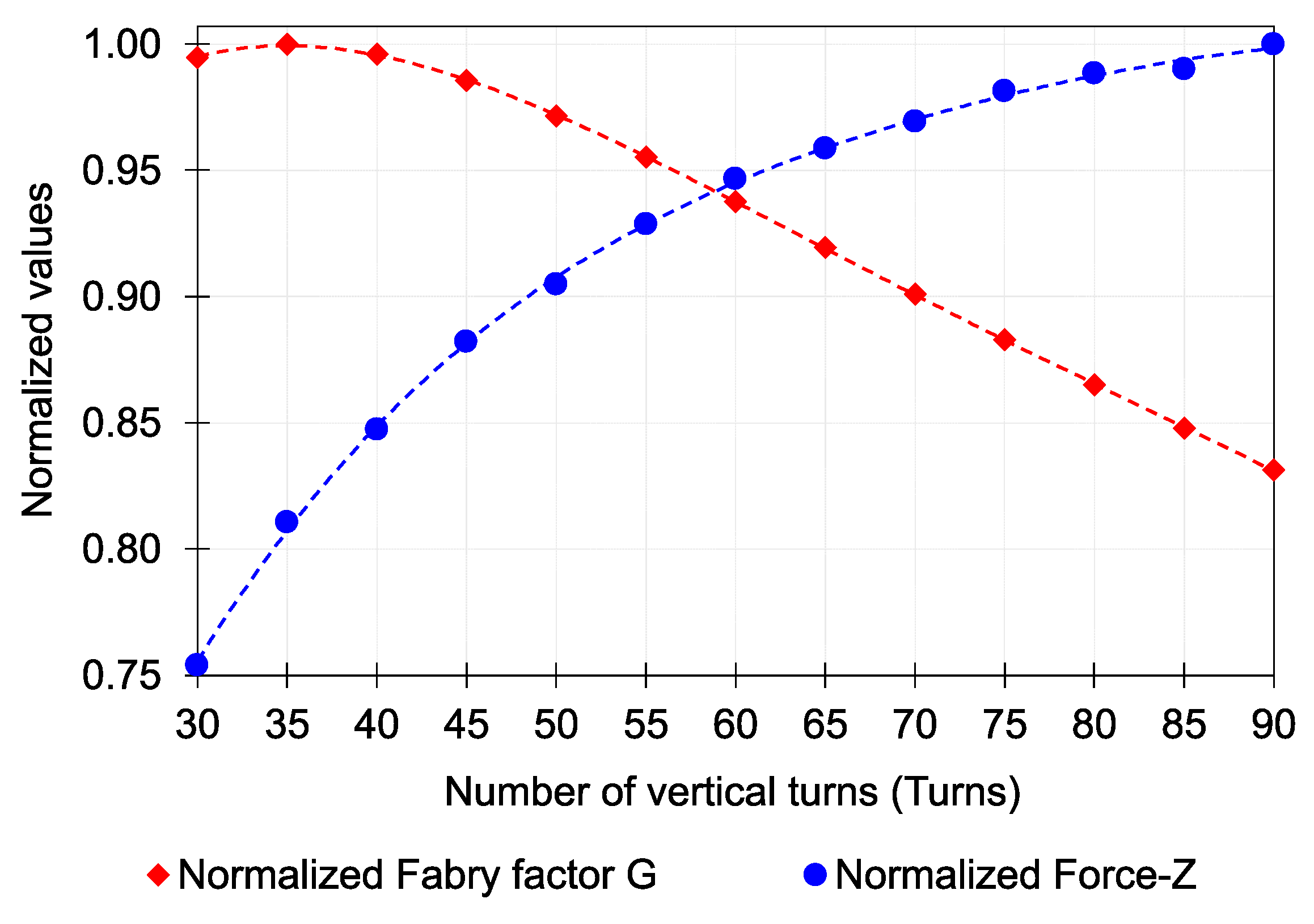
The normalized values of the Fabry factor and the vertical force are plotted in Figure 4. From the plot, the optimal number of vertical winding turns was close to 60 turns or an estimated height of 86.50 mm. Hence, the number of vertical winding turns of 60 turns was selected. All designed parameters of the square coil are summarized in Table 3.

2.2. Stator Array Configuration

After the square coil was designed, the arrangement of the planar coil array was considered. With a disc magnet mover, only five degrees of freedom can be controlled except for rotation about the vertical axis or yaw motion. The minimum number of coils to control the levitation of a single disc magnet is five as shown in [22]. For the planar maglev system, the surrounding coils were added to form the planar coil array. The planar coil array stator in this design initially had 9 coils arranged in a 3 by 3 array or straight configuration. The coil pitch or distance from center to center of the coil along the x and y axes was 76.2 mm (3 inches) to maximize the packing density of the array.
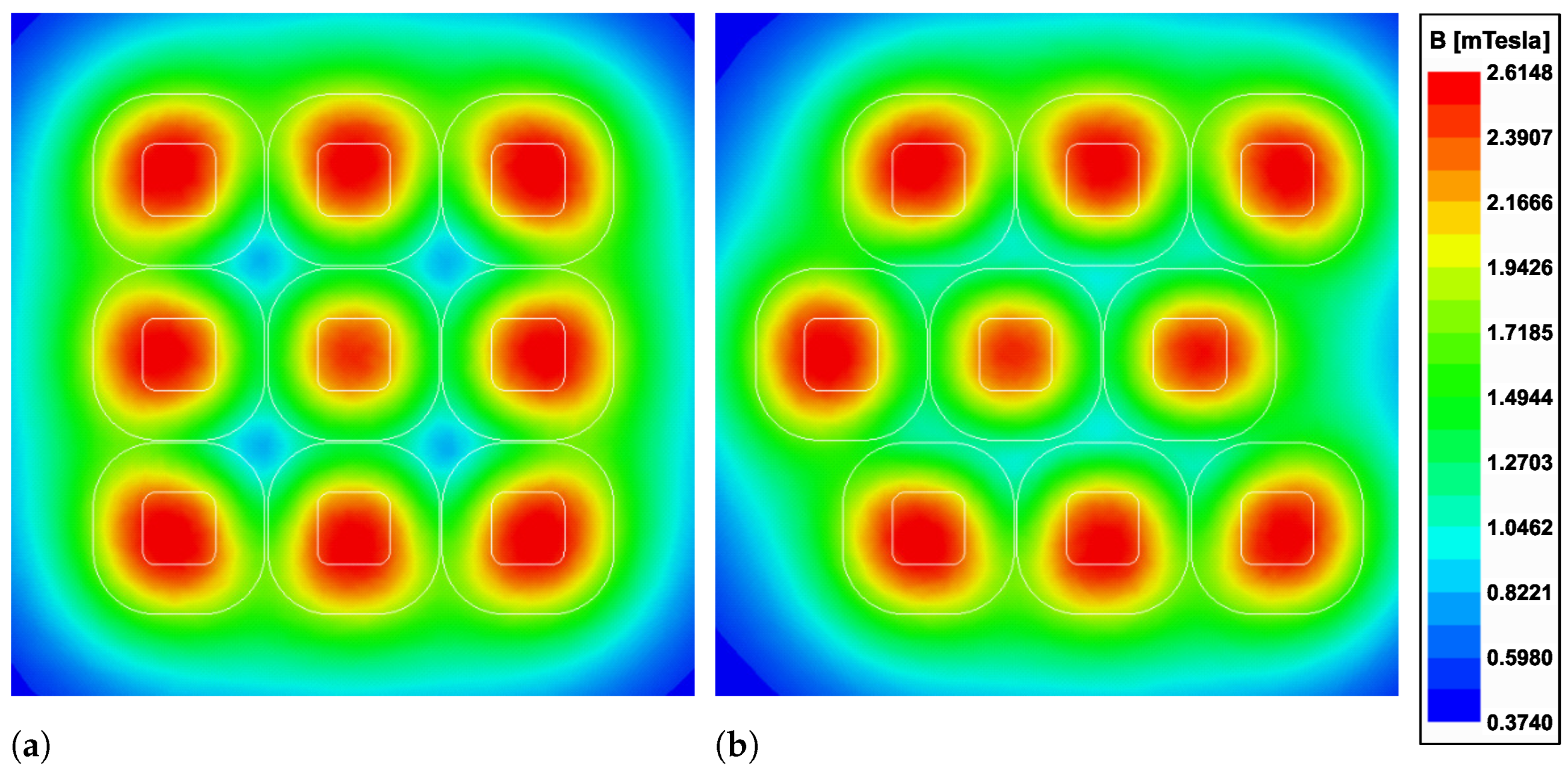
Two array configurations, namely straight and zigzag, were analyzed in this work. Both arrays had nine coils arranged with configuration parameters as detailed in Table 3. The zigzag array had a 38.1 mm (1-1/2-inch) offset for the middle row. The plots of the magnetic flux density at 20 mm above the two arrays are depicted in Figure 5. The significant difference between these two configurations can be observed at the corner between coils. The zigzag array could provide a better uniform magnetic flux density within the array than the straight array. In this work, the zigzag configuration was selected. An additional coil was added to the right side of the middle row for array symmetry.

2.3. Compact Planar Maglev System Structure and Permanent Magnet Mover

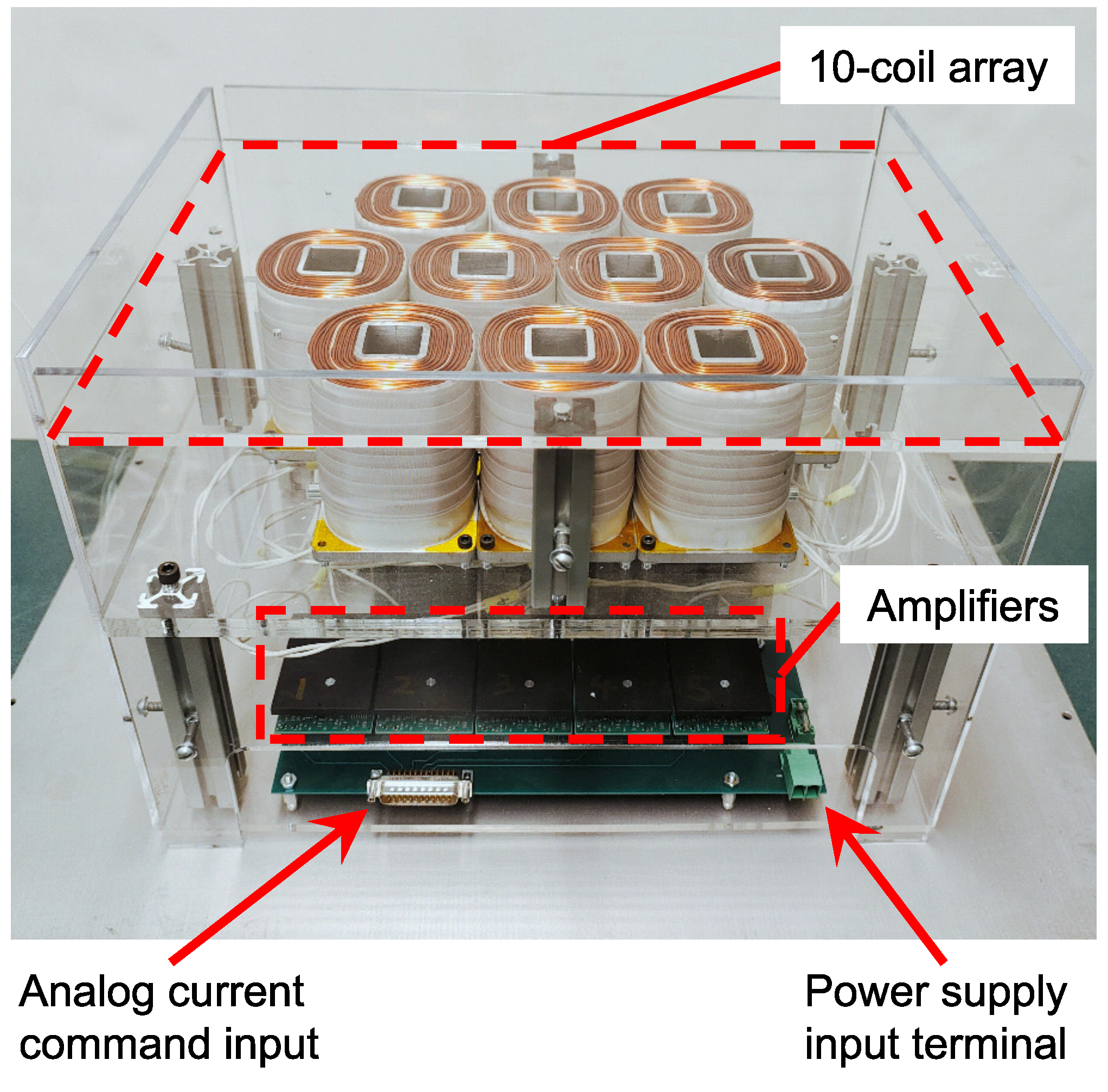
Figure 6 represents an overview of the proposed compact planar maglev prototype with system specifications in Table 4. The overall dimensions of the planar stator module were 320 mm wide, 410 mm long, and 290 mm high, with a total weight of 36 kg. The top level was an array of ten coils arranged in the zigzag configuration as designed. The prototype was covered and surrounded by acrylic sheets for mechanical and electrical safety.
The bottom level had two current amplifier boards. Each amplifier board had five current amplifier units to control five coils individually. The current amplifier (AZB20A8, ADVANCED Motion Controls, Camarillo, United States) received the ± 10 V analog current command signal from the controller with a supply voltage of 36 VDC.
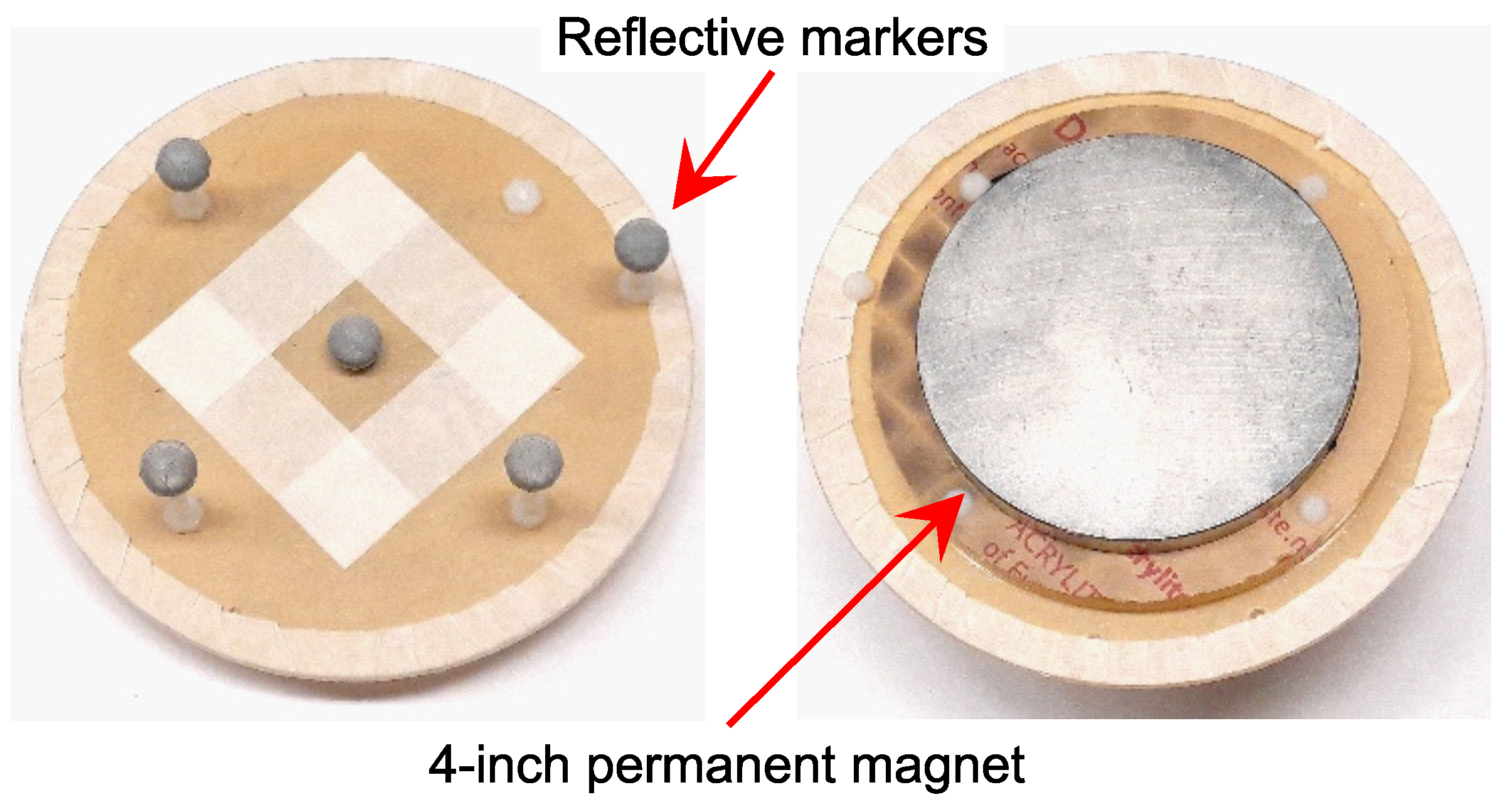
The PM mover in this work was a 101.60 mm (4-inch) diameter × 12.70 mm (1/2-inch) thickness neodymium disc magnet grade N50. The magnet was mounted to the acrylic frame equipped with reflective markers on the top with different heights for motion tracking as shown in Figure 7. The total weight of the mover was approximately 900 g.

3. Working Principle and Modeling

With the designed planar maglev system, the working principle of the proposed maglev system is described in this section. First, the coordinate systems are set. Then, the Lorentz force based wrench–current model is formulated. The solution to the triple integral using the magnetic nodes approach and numerical integration is presented.

3.1. Coordinate System Settings

Figure 8 depicts the three main coordinate systems in this work, namely, the world {w}, mover {m}, and coil {c} coordinates. The world coordinate is set at the center of the coil array top surface. The mover coordinate is at the center of the disc magnet. Each coil coordinate frame origin is defined at the centroid of the corresponding coil with arbitrary location inside its volume as point p. The superscript and subscript of a vector are used to represent the direction from end location to start location and to which coordinate systems they are referring, respectively. Without the superscripts, the vectors only indicate in which coordinate frame they are expressed. For instance, r w 21 represents a vector r from location 1 to location 2 expressed in the world coordinate system. The subscript of the coordinate transformation matrices represents the relationship between coordinate systems, such as T w c to represent a transformation from mover coordinates to world coordinates. Additionally, there is a sensor coordinate system, which is easily adjusted to overlap with the world coordinate system after calibration.

3.2. Lorentz Force

Finding the relationship between the stator current density ( J ) and forces ( F ) and torques ( T ) generated on disc magnet was the fundamental component of this system. The Lorentz force law was utilized in this study. Given both the mover-generated magnetic fields and corresponding current density on coil locations, the reaction forces and torques on the mover at a particular pose could be obtained as follows:
F w = V J w ( p ) × B w ( p ) d V ,
T w = V r w p o m × J w ( p ) × B w ( p ) d V .
  • p ( x p , y p , z p ) represent arbitrary world points on the coils.
  • o m represents the location of the center of the magnet in the world coordinate system, which can be obtained from the sensor returned mover pose (x, y, z, ψ , θ , ϕ ).
  • V represents the integration volume of the coils.
  • F w and T w represent the resultant forces and torques vectors generated on the mover in the world coordinate system, respectively.
  • J w and B w represent the location p current density and magnetic flux density obtained in world coordinate system, respectively.

3.3. Magnetic Flux Density Computation

It is difficult to find the analytical solutions to Equations (2) and (3) for the maglev system in real-time control. Alternative solutions, numerical methods, such as the Gaussian quadrature method [28], can be applied to solve for forces and torques in real time. However, it could not be reimplemented on the proposed system due to limitations on the computation power of the controller in this work. In addition to the numerical method, the magnetic nodes approach [25] can be used to find the magnetic flux density B c ( p ) generated by the magnet mover at any location in the mover frame expressed as
B k ( p ) = ( 1 ) k 1 B r 4 π ln y r + r p r k 2 ln x r + r p r k 2 arctan x r y r z r r p r k 2 ,
where x r = x p x k , y r = y p y k , z r = z p z k , and  r p r k 2 = ( x r ) 2 + ( y r ) 2 + ( z r ) 2 .
In this work, the disc magnet was modeled with 116 nodes for both top and bottom levels. Therefore, there were 232 nodes in total. The total magnetic flux density at arbitrary point p could be computed by
B m ( p ) = k = 1 232 B k ( p ) .
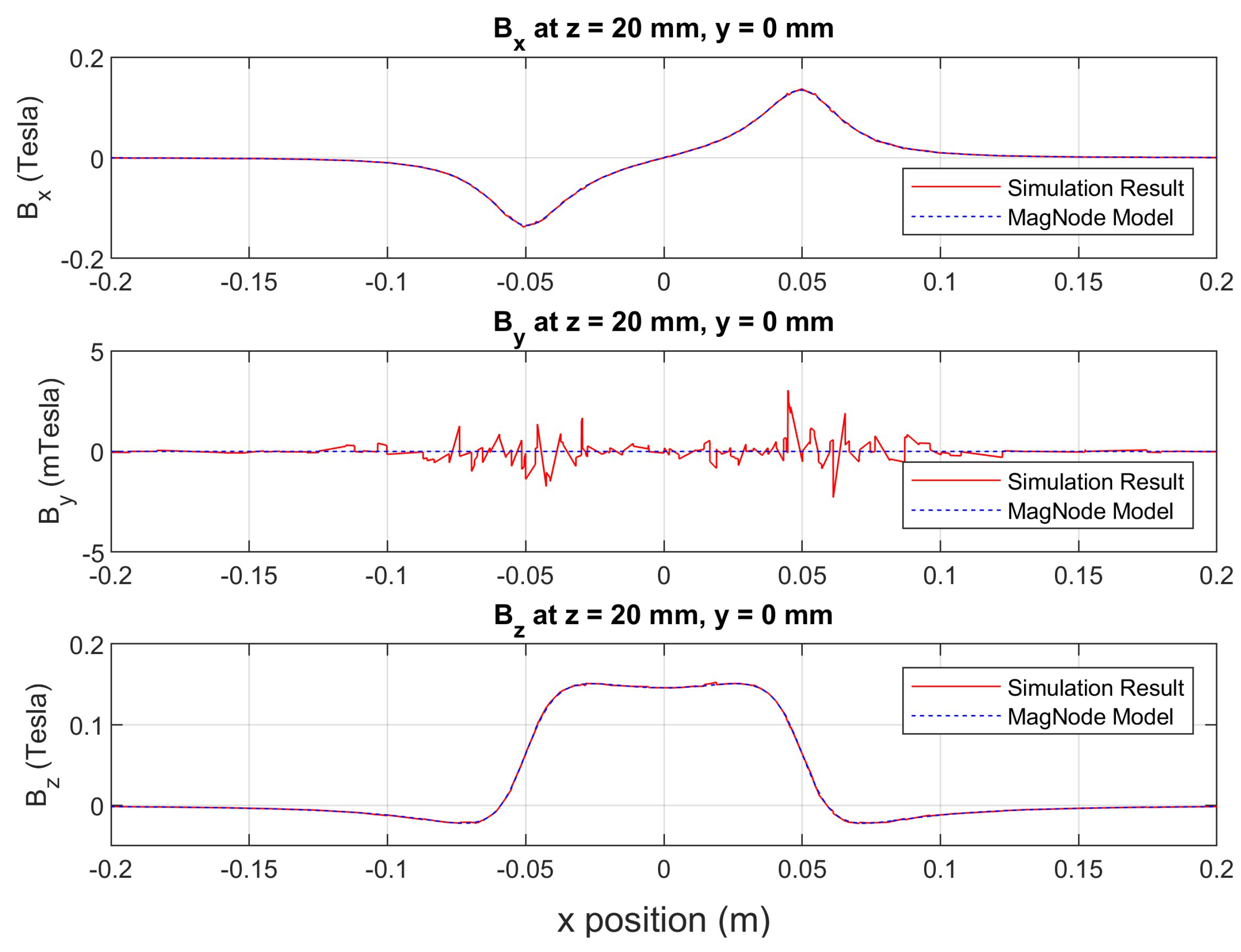
The equations shown above were all expressed in the mover coordinate system. Later, the obtained magnetic flux density was transformed into the world coordinate system. Numerical results of the magnetic flux density of the 4-inch disc magnet were verified with simulation results in ANSYS Maxwell as shown in Figure 9. The magnetic flux density components were computed at 20 mm above the center of the magnet along the x axis from −200 mm to 200 mm.
With the obtained magnetic flux density components, the Lorentz forces and torques could be computed for each square coil with the following coil segmentation strategies.

3.4. Numerical Integration for Magnetic Force and Torque Model

To solve the triple integrals in Equations (2) and (3), the square coil model was separated into eight sections, four straight sections and four corner sections. With a segmentation of all coil sections into small elements, the triple integrals in Equations (2) and (3) could be estimated as the summations of the results from each element. Since all results were expressed in the world coordinate system, the magnetic flux density results from Equations (4) and (5) were transformed into the world coordinate system by
B w ( p ) = R w c · B c ( p ) = R x · R y · R z · B c ( p ) .
The rotation matrix R x y z was easily obtained based on Euler angles (in X−Y−Z order) of the mover ( ψ , θ , ϕ ), measured in the world coordinate system.

4. Control System

After obtaining the Lorentz force and torque models, this section provides the details of the real-time implementation of the 5-DOF controller.

4.1. Control Algorithm

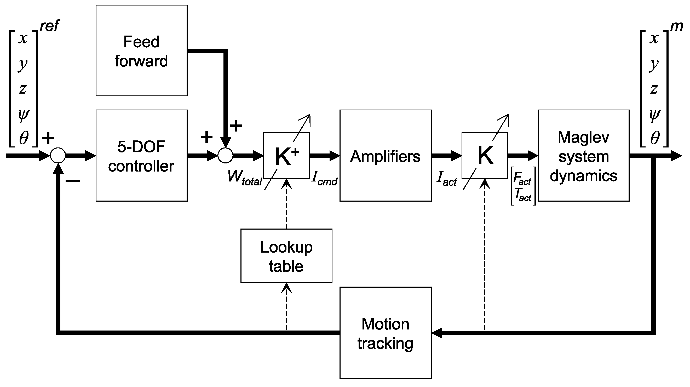
An overall 5-DOF control diagram is illustrated in Figure 10. By using the wrench–current transformation, the cross-coupling effect could be decoupled and a 5-DOF PID controller was applied to control each degree of freedom separately. The precomputed wrench–current transformation matrices were stored in the lookup table. The transformation matrix could be looked up by using the moving pose obtained from the motion tracking system. Additional feed-forward control was used to compensate for the mover weight in a vertical motion.
The tuned PID parameters for the proposed system are shown in Table 5. It is worth noting that the PID parameters were different on the x and y axes. Similarly, the parameters were different on the ψ and θ axes. Due to the zigzag configuration of the ten-coil array as shown in Figure 8, the different arrangements of the coils along the x and y axes featured the maglev system controller with different PID parameters along the x and y axes. Therefore, the tuned parameters were different on the axes. The units of the PID gains were selected as SI units. For rotations, due to the difficulty of the system to generate large torques, the gains were relatively small quantities with SI units.

4.2. Decoupling Method Using Wrench–Current Transformation Matrix

The proposed ten-coil planar maglev system was a MIMO overactuated system with ten coil current inputs and 5-DOF motion outputs. The yaw rotation around the z axis could not be controlled because of the axial symmetry of the disc magnet. Therefore, the torque about the z axis was not considered in the control design. From the Lorentz force law in the previous section, the forces and torques were proportional to the coil currents I . Therefore, the force and torque equations as a function of coil currents could be written as
F w T w 5 × 1 = K ( x , y , z , ψ , θ ) I = f x 1 f x k f x 10 f y 1 f y k f y 10 f z 1 f z k f z 10 t x 1 t x k t x 10 t y 1 t y k t y 10 · i 1 i k i 10
where K is the commutation matrix. It represents the relationship between the coils and the forces and torques on the magnet at specific pose ( x , y , z , ψ , θ ) when each coil is supplied with a 1 A current.
In the control system, the total wrench (forces and torques) command W t o t a l from the 5-DOF PID controller and feed-forward controller was decoupled and transformed to coil current command I c m d by
I c m d = K + W t o t a l
where the wrench–current transformation matrix or wrench matrix K + is an inverse of the commutation matrix. Since the commutation matrix is usually a nonsquare matrix, the Moore–Penrose pseudoinverse can be computed instead, expressed by
K + = K T ( K K T ) 1 .
Next, the implementation of the wrench–current transformation matrix for decoupling using the lookup table is presented.

4.3. Lookup Table

Since the wrench–current transformation matrix is a function of the mover pose, the real-time solution of this matrix must be computed for every control sampling. However, numerically computing the Lorentz forces and torque cannot be implemented in real time. Hence, in this work, the wrench–current transformation matrices within a specific range of motion were precomputed and stored in a lookup table.
To keep the size of the lookup table reasonable while providing sufficient information for the operational space, a 5-D table with a 1 mm grid on both x and y axes from −10 mm to 10 mm, 1 mm grid on z axis from 18 mm to 26 mm, and a 5-degree grid on both ψ and θ axes from −10 degrees to 10 degrees was created. The matrix with corresponding mover pose closest to the current mover pose was returned while searching the lookup table at runtime. This lookup table approach helped reduce the computation cost by sacrificing the controller memory. Only a finite number of mover poses were stored. Therefore, it was inevitable to use lookup results when the operation location was not in the lookup data. By applying a multidimensional linear interpolation approach, the transformation matrix could be estimated for the desired pose instead of using the nearest data.

4.4. Multidimensional Linear Interpolation

The closest pose search of the lookup table was utilized at runtime to find the current outputs. Therefore, inconsistent errors were expected when switching selected matrices, which degraded the overall controller performance. To improve the real-time control performance, a multidimensional linear interpolation method was introduced to smooth out the errors brought by data switching.
The interpolation could be formulated as follows. The  a x , a y , a z , a ψ , and  a θ were used to represent the weighting parameters for the multidimensional linear interpolation of the x, y, z, ψ , and  θ states of the mover pose, respectively. Suppose that the random 5-DOF pose to be interpolated was at ( x 0 , y 0 , z 0 , ψ 0 , θ 0 ), which was between the state pairs, ( x 1 , x 2 ) , ( y 1 , y 2 ) , ( z 1 , z 2 ) , ( ψ 1 , ψ 2 ) , and  ( θ 1 , θ 2 ) , respectively. The weighting parameters could be calculated by
a p = p 0 p 2 p 1 p 2 with p 1 p 0 p 2
where p can be the x, y, z, ψ , or  θ state. This formula could be generalized for extrapolation purposes. Once the weighting parameters were obtained, the general results of the interpolated wrench matrix could be found for any desired states as expressed in
K 0 = i = 1 2 j = 1 2 k = 1 2 l = 1 2 m = 1 2 s = x i θ m a s · K x i , y j , z k , ψ l , θ m .
For n-dimension or -state interpolation, a total of 2 n number of wrench matrices were needed. Then, we applied Equation (11) as explained in Algorithm 1 to find K 0 . In the 5-D case, there were 32 wrench matrices to extract. Due to controller constraints, only a 2-D linear interpolation was implemented with two combinations of xy and ψ θ axes separately.
Algorithm 1 Multidimensional linear interpolation
Require: A precomputed lookup table
Input: The sensor mover pose readings x 0 , y 0 , z 0 , ψ 0 , and  θ 0 , only work with the states needed
Output: The interpolated results K 0
 Initialization K 0 = zeros(5, 10), n as the number of states selected
 Calculate the weights a p 1 = p 0 p 2 p 1 p 2 and a p 2 = 1 a p 1
 while i 2 n do {n while loops to be precise}
      lookup K i
      find the a s product
       K 0 = K 0 + a s · K i
       i = i + 1
end while

5. Experimental Setup and Results

This section presents the levitation experiment results of the proposed ten-coil planar maglev system. First, the maglev system is discussed. Then, the effectiveness of the linear interpolation is evaluated. Finally, the fine-step motion and long-range motion are performed to demonstrate the system performance.

5.1. System Setup

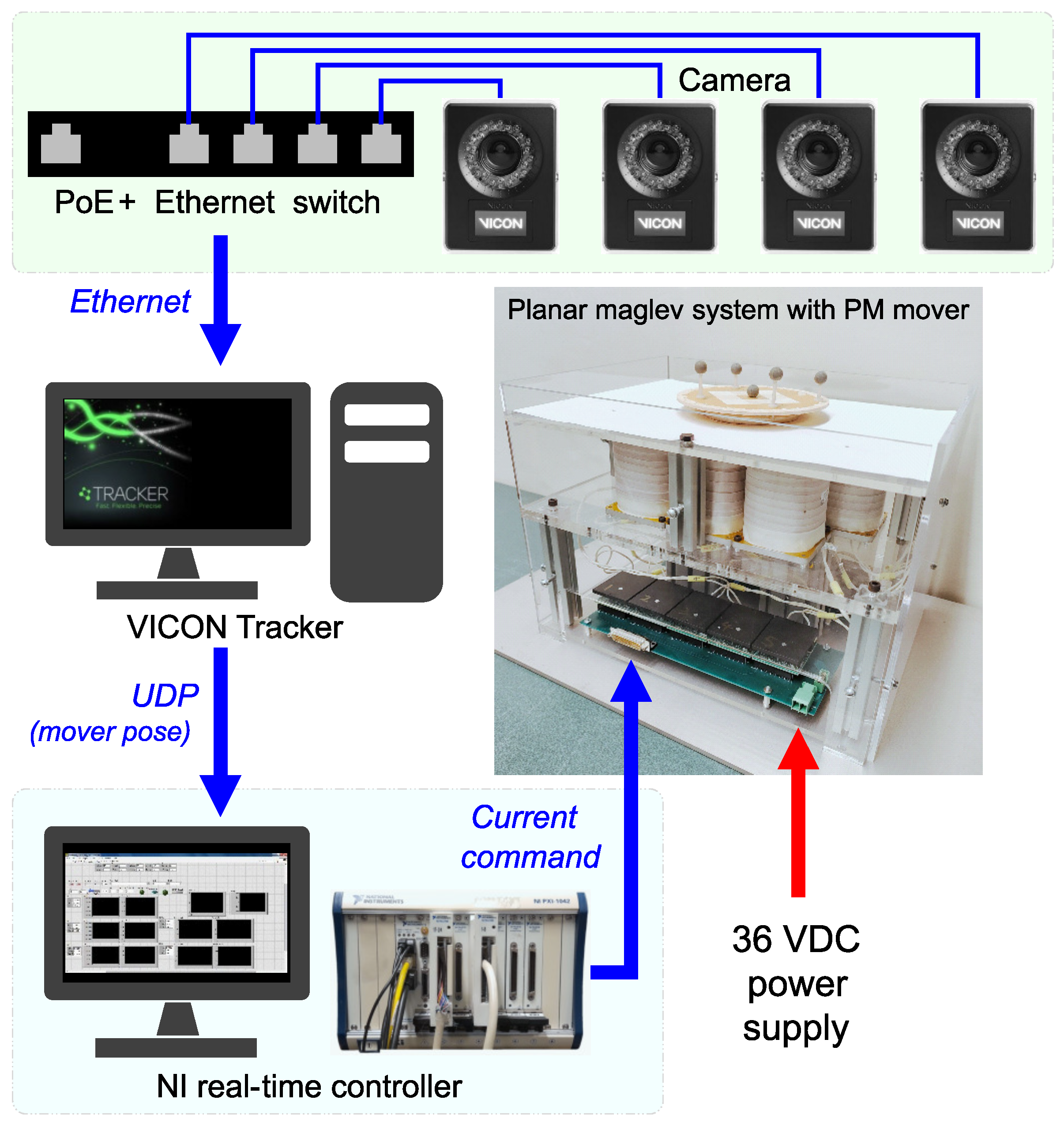
Figure 11 represents the overall setup of the proposed planar maglev system with the motion-tracking system and controller. The motion-tracking system had four cameras (VICON Vantage V5, Vicon Motion Systems, Oxford, United Kingdom) to detect the reflective markers on the mover. Then, the data were transmitted over Ethernet to a software program to compute the mover position and orientation. With a proper calibration, the motion-tracking system could provide position and orientation data with a ±10 μ m and ±0.2 mrad resolution with an update frequency of 1 kHz to the controller via the UDP protocol. With the same sampling frequency of 1 kHz, the controller (NI PXI-8820, National Instruments, Austin, United States) operated with the implemented control algorithms as described in the previous section to determine the coil currents. The analog current command outputs were sent out through two analog output modules to the current amplifiers in the planar maglev system.

5.2. Linear Interpolation Performance Verification

The PID parameters in Table 5 were used to verify the performance improvement with and without the linear interpolations, on both combinations of xy and ψ θ axes. In Figure 12, the ψ θ axes’ linear interpolation was able to eliminate the sharp oscillation effect when switching wrench matrices in the lookup table. Because the grid size of the lookup table on the ψ θ axes was five degrees, larger error gaps were expected at the switching location. On the xy axes, the step response at the wrench matrix switching location showed its performance with constant oscillations. There were smaller oscillations on the x axis than on the y axis, due to the coil layout configurations. The xy axes’ linear interpolation could reduce the additional source of oscillations caused by the uncontrollable yaw rotation effect on the xy step responses and xy steady-state errors shown in Figure 13 and Figure 14, respectively. To smooth out the overall errors, applying a linear interpolation is one of the approaches to achieving so. The results showed that the control performance improved with no further tuning needed.

5.3. Step and Microstep Responses

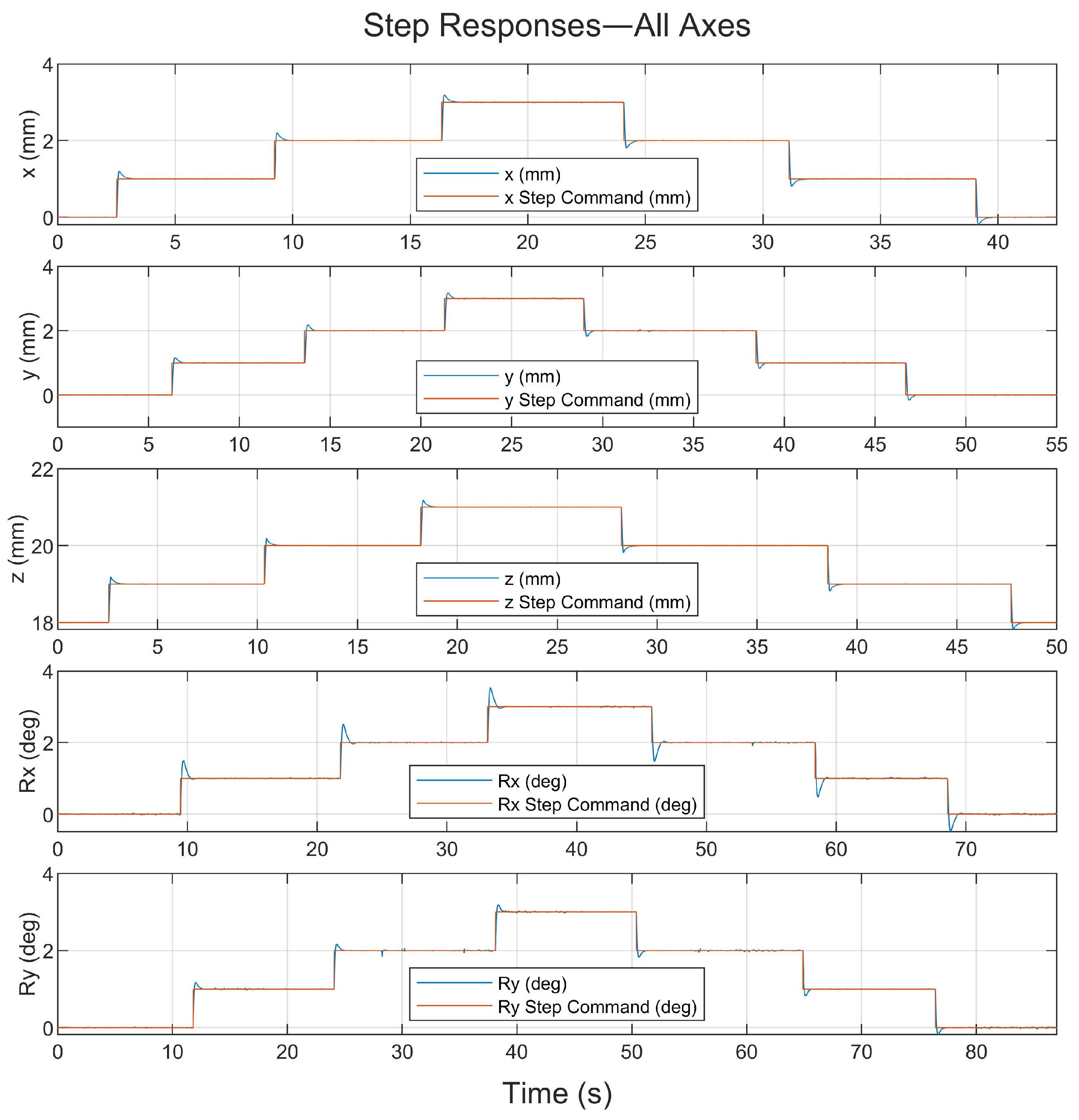
First, the mover was controlled to move with a step motion of 1 mm in the x, y, and z axes for translation. For rotation, the mover was rotated with a one-degree step for both roll and pitch motion. The step response results of all five types of motion are plotted in Figure 13. The characteristics of the step response are provided in Table 6.
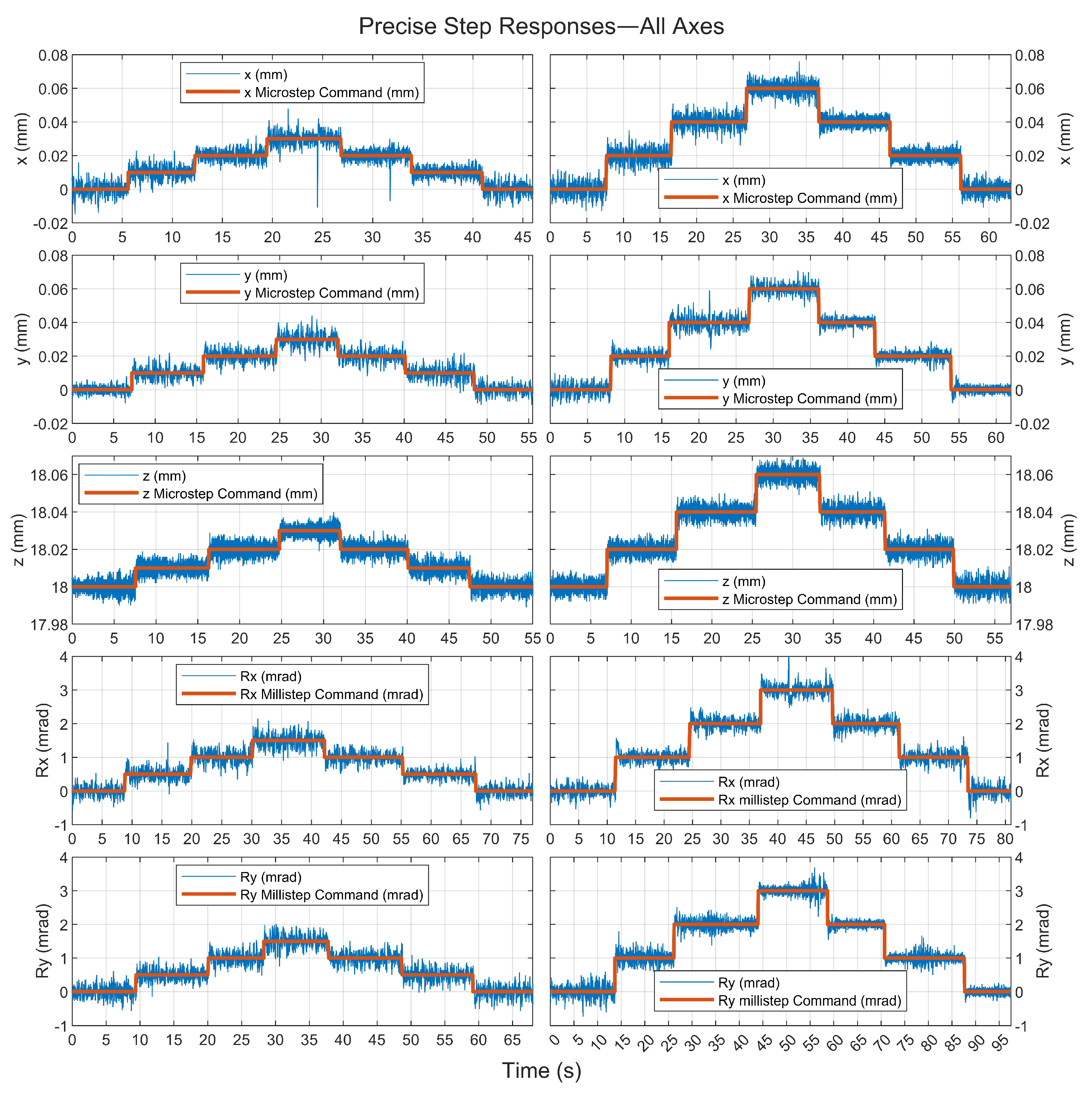
Next, the precision motion performance of all five types of motion, x, y, z, ψ , and θ , is shown in Figure 14. The proposed planar maglev system could be controlled with the precise step of 10 μ m in the x, y, and z axes, and 0.5 mrad in roll ψ and pitch θ . An unexpected spike was observed in some motion results. The precise step performances were almost limited by the sensor resolutions. These performance results indicate that the system was capable of precise control on all axes.

5.4. Full-Range Trajectory Tracking

To demonstrate the full-range motion of the proposed system, two experiments were conducted. One was focused on translational trajectory tracking. The other was focused on the rotational ramp command following.
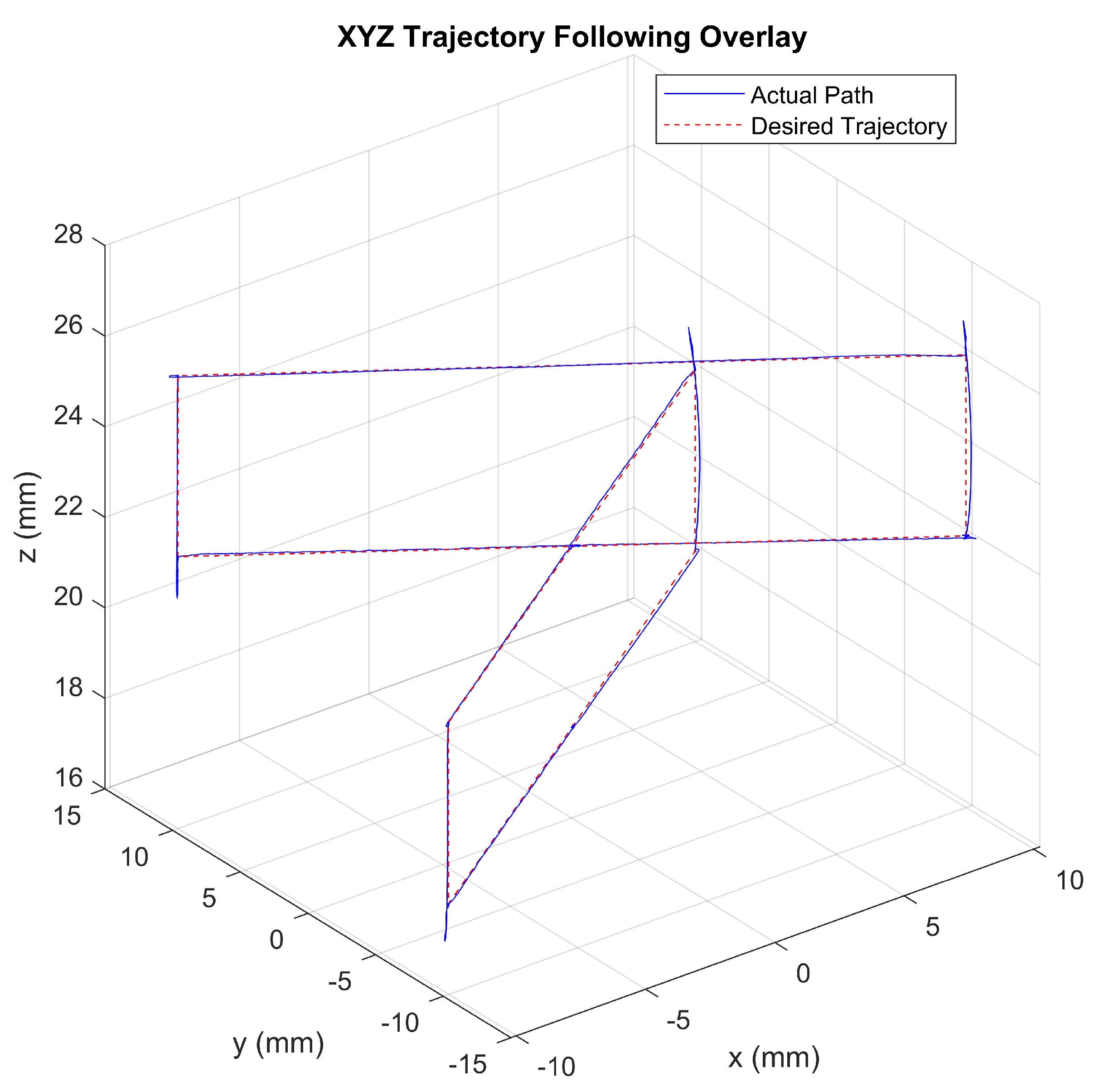
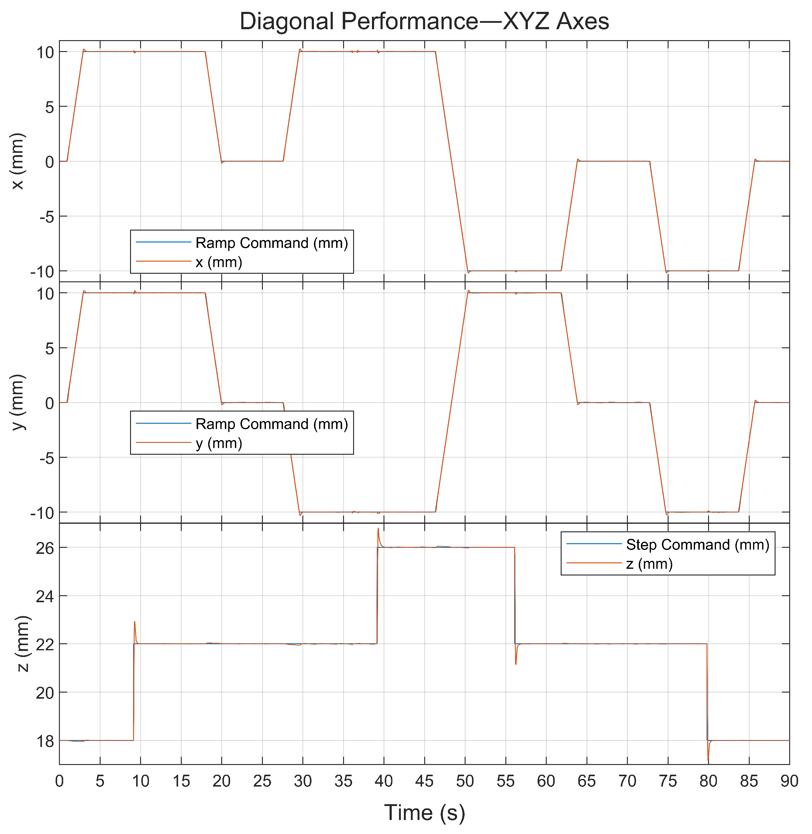
For trajectory tracking in translation, the motion range was defined to be equal to the lookup table data range, which ranged from −10 mm to 10 mm on both x and y axes, and 18 mm to 26 mm on the z axis. Figure 15 represents the full-range motion in the lookup region and the motion of each axis is shown in Figure 16. Note that the ramp commands were applied on the x and y axes only. The z axis was controlled with step commands. Therefore, large overshoots along the z axis could be observed.
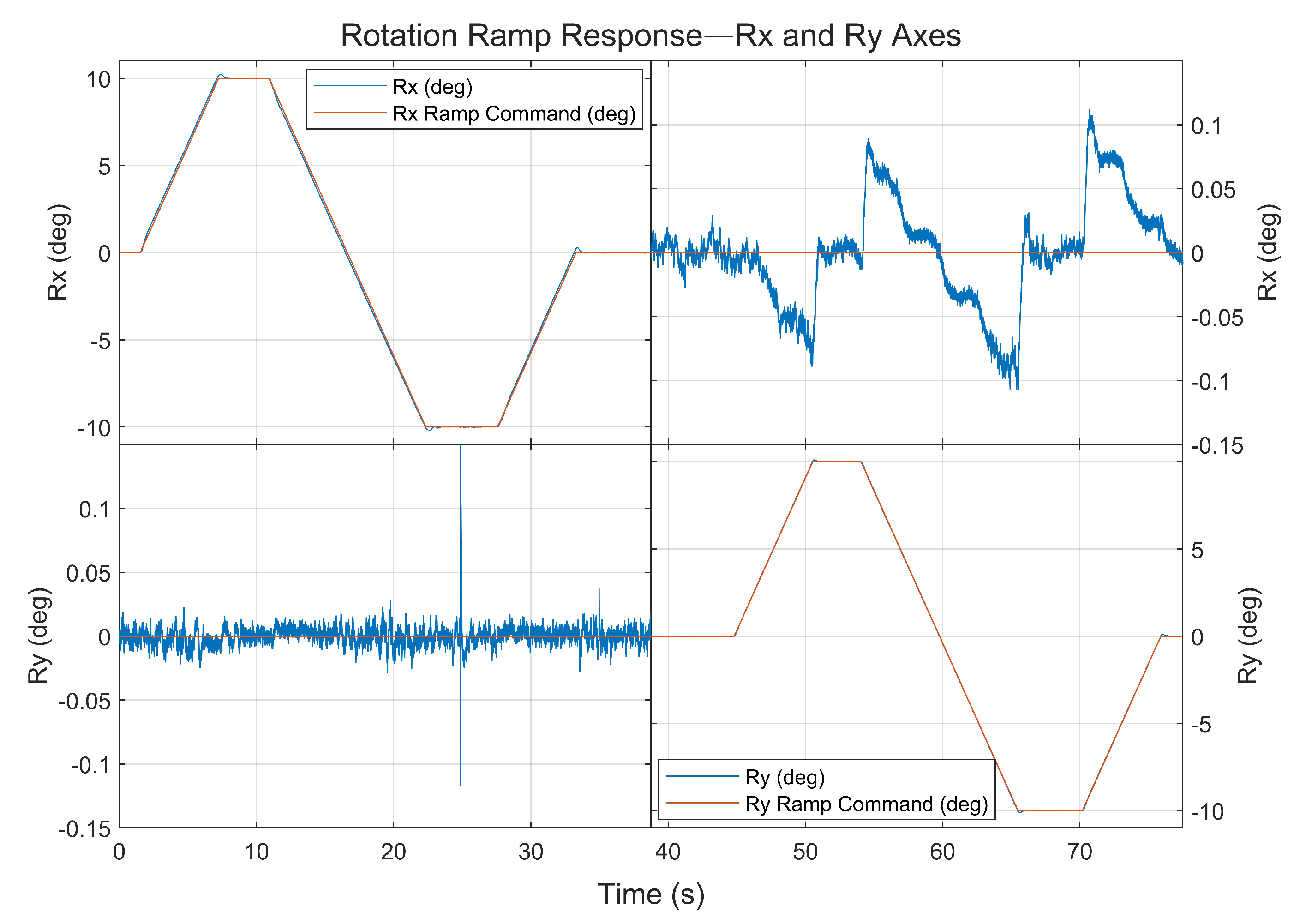
For the rotation motion, to avoid the mover colliding with the base surface at a maximum rotation angle, the mover had to be levitated with a 26 mm air gap. The results of the full-range rotation with the ramp command are shown in Figure 17. The mover was rotated with roll ψ for ±10 degrees. Then, the mover rotated with the same rotation range for pitch θ . Figure 18 represents the mover was levitated at 26 mm and rotated with pitch angle θ of 10 degrees. The results were recorded at the same time scale. Each column used different vertical scales to fit with the motion results.

6. Discussion

This section provides a discussion of the proposed compact planar maglev system design and levitation experiment results.

6.1. Compact Planar Maglev Design

The proposed compact maglev system had a planar square coil array to achieve both fine and long-range motion controls. The round-corner square coil was initially designed by the Fabry factor as it resembled the cylindrical coil. With the magnetic flux density comparison, the coil height was thereby optimized to achieve a high levitation force with acceptable power efficiency. Even though the zigzag array was better, the straight array might be more suitable to build as a compact module for an expanded work area. The design of the magnet mover will be important for efficiency in levitation.
For the development of an expandable planar maglev system, two main components must be considered: system communication and motion-tracking system. The analog signal command in this work might not be suitable for a large area. The control and current driver components with automation protocols will provide more robust communication. The vision system is flexible for scalable areas. However, the larger the tracking area, the worse the motion-tracking quality.

6.2. Levitation Experiment Results

The experiment results demonstrated both precision motion and long-range motion. The 2-D linear interpolation could enhance the wrench–current transformation. The effectiveness of the interpolation was tested by moving the mover to the location with no data available in the lookup table. For high-precision motion, the mover was controlled to move with steps of 10 and 20 μ m for translation and 0.5 and 1 mrad for roll and pitch. The precision of the system was limited by the motion sensor.
To prove the concept of long-range motion, the mover was moved within the horizontal area of 20 mm × 20 mm with a vertical motion range from 18 mm to 26 mm. The rotation range was ±10 degrees for both roll and pitch. A large overshoot could be observed in large-step motion. Even though the multidimensional linear interpolation could improve the levitation as discussed, the real-time solution to decouple the wrench command was still important.
From the experiment results, there were two main problems that significantly deteriorated the levitation performance: undesired yaw motion and system lag. In the experiments, the untethered mover was suspended in the air with five controllable degrees of freedom. Imperfect control efforts could result in an undesired yaw motion, especially, during the large motion. Unwanted rotation could cause oscillations in other axes.
Next, the authors believe that the reason for the large spikes in both precision and long-range motion might be the limitation of the old controller hardware. Prior to the experiment, large spikes occurred frequently when too many features were implemented. Therefore, the linear interpolation was limited to 2-D with a ramp command feature to reduce the computational load in this work.
By comparing with other previous works, the proposed planar maglev prototype had several advantages and room for improvement. First, for the range of motion, the system could move with a long range, especially in the vertical direction with a 26 mm levitation gap, compared to other works with the disc magnet [22] and Halbach array [21]. A solution for unlimited translation is needed since the horizontal range was relatively small and yaw motion was not controlled. Next, the fine-step motion of 10 and 20 μ m demonstrated an improvement of this system compared to other works with disc magnets [23,30]. The precision motion quality can still be improved for better performance such as that of the Halbach array [17].
From the discussions above, there are plenty of research opportunities for the design and levitation performance of the proposed planar maglev system. For educational purposes, a cost-effective planar maglev system using inexpensive sensors and a controller can be built as found in [33]. For precision motion, with the most recent review in [34], the challenges lie in solutions for effective fine-level sensing, long-range extension, and extreme performance such as high-speed motion. In high-speed motion or long-time use, the coils must consume a lot of currents and heat up quickly. The generated heat will affect levitation performance. The analysis of the thermal model [35] and the design of the cooling system are important. The eddy current damping, produced by array cover materials such as aluminum, could improve the stability even though it affects the speed. However, the selected material must be optimized to avoid an excessive damping force on the mover [36]. Lastly, advanced control can be applied for complicated tasks, for example, iterative control for higher precision in repetitive motion [19,37], or a study on transient responses with external disturbances and the design of a robust controller to improve levitation performance in real-world applications.
7. Conclusions and Future Work

In this work, a compact planar maglev prototype was developed to be capable of both precision and long-range motion. The stator was designed as a compact module. The coil array consisted of ten optimized square coils arranged in a zigzag pattern. The single magnet mover was deployed with five-DOF motion. The experiment began with the evaluation of the decoupling enhancement approach. The 2-D linear interpolation was able to reduce the oscillations which occurred when the mover was at the switching location, by estimating the data at that location to smooth the motion. Next, for step and microstep motion, the experiment results demonstrated the mover was moved with steps of 10 and 20 μ m for translation and 0.5 and 1 mrad for roll and pitch. Finally, full-range motion tests were conducted. The mover was moved following the trajectory within the range of 20 mm × 20 mm × 8 mm with a maximum air gap of 26 mm. The rotation range was ±10 degrees for both roll and pitch. Levitation results for microstep and full-range motion demonstrated that the proposed planar maglev design had the potential to increase flexibility for manufacturing systems as a machining workstation and an expandable modular omnidirectional conveyor.
Future work of this research will mainly aim to achieve six-DOF motion with unlimited horizontal motion range. The stator design will be further developed into a modular structure to provide flexibility in its arrangement. Accurate real-time wrench–current transformation solutions and improved motion-tracking techniques will elevate the levitation performance.

Author Contributions

Conceptualization, C.T., Y.W. and M.B.K.; methodology, C.T. and Y.W.; software, C.T. and Y.W.; validation, C.T., Y.W. and M.B.K.; formal analysis, C.T. and Y.W.; investigation, C.T. and Y.W.; resources, C.T. and Y.W.; data curation, C.T. and Y.W.; writing—original draft preparation, C.T. and Y.W.; writing—review and editing, M.B.K.; visualization, C.T. and Y.W.; supervision, M.B.K.; project administration, M.B.K.; funding acquisition, M.B.K. All authors have read and agreed to the published version of the manuscript.

Funding

This work was supported by the Canada Foundation for Innovation (CFI) and the Natural Sciences and Engineering Research Council of Canada (NSERC).

Institutional Review Board Statement

Not applicable.

Informed Consent Statement

Not applicable.

Data Availability Statement

Data available from the authors upon request.

Conflicts of Interest

The authors declare no conflict of interest.

References

  1. Lee, H.W.; Kim, K.C.; Lee, J. Review of maglev train technologies. IEEE Trans. Magn. 2006, 42, 1917–1925. [Google Scholar]
  2. Nøland, J.K. Prospects and challenges of the hyperloop transportation system: A systematic technology review. IEEE Access 2021, 9, 28439–28458. [Google Scholar] [CrossRef]
  3. Abbott, J.J.; Diller, E.; Petruska, A.J. Magnetic methods in robotics. Annu. Rev. Control Robot. Auton. Syst. 2020, 3, 57–90. [Google Scholar] [CrossRef]
  4. Zhang, X.; Khamesee, M.B. Automatic pick-and-place using a magnetically navigated microrobot and a motorized micromanipulator. Microsyst. Technol. 2020, 26, 1733–1744. [Google Scholar] [CrossRef]
  5. Ur Rahman, M.S.; Tahir, M.A.; Noreen, S.; Yasir, M.; Ahmad, I.; Khan, M.B.; Ali, K.W.; Shoaib, M.; Bahadur, A.; Iqbal, S. Magnetic mesoporous bioactive glass for synergetic use in bone regeneration, hyperthermia treatment, and controlled drug delivery. RSC Adv. 2020, 10, 21413–21419. [Google Scholar] [CrossRef] [PubMed]
  6. Kazemzadeh Heris, P.; Khamesee, M.B. Design and fabrication of a magnetic actuator for torque and force control estimated by the ANN/SA algorithm. Micromachines 2022, 13, 327. [Google Scholar] [CrossRef]
  7. Pedram, S.A.; Klatzky, R.L.; Berkelman, P. Torque contribution to haptic rendering of virtual textures. IEEE Trans. Haptics 2017, 10, 567–579. [Google Scholar] [CrossRef]
  8. Wang, S.; Li, H.; Yuan, D.; Wang, S.; Wang, S.; Zhu, T.; Zhu, J. Oscillations and size control of Titanium droplet for electromagnetic levitation melting. IEEE Trans. Magn. 2018, 54, 1–4. [Google Scholar] [CrossRef]
  9. Smirnov, A.; Uzhegov, N.; Sillanpää, T.; Pyrhönen, J.; Pyrhönen, O. High-speed electrical machine with active magnetic bearing system optimization. IEEE Trans. Ind. Electron. 2017, 64, 9876–9885. [Google Scholar] [CrossRef]
  10. Kumar, P.; Malik, S.; Toyserkani, E.; Khamesee, M.B. Development of an electromagnetic micromanipulator levitation system for metal additive manufacturing applications. Micromachines 2022, 13, 585. [Google Scholar] [CrossRef]
  11. Compter, J.C. Electro-dynamic planar motor. Precis. Eng. 2004, 28, 171–180. [Google Scholar] [CrossRef]
  12. Cao, J.; Zhu, Y.; Wang, J.; Yin, W.; Duan, G. A novel synchronous permanent magnet planar motor and its model for control applications. IEEE Trans. Magn. 2005, 41, 2156–2163. [Google Scholar] [CrossRef]
  13. Kim, W.J.; Trumper, D.L. High-precision magnetic levitation stage for photolithography. Precis. Eng. 1998, 22, 66–77. [Google Scholar] [CrossRef]
  14. Schaeffel, C.; Katzschmann, M.; Mohr, H.; Gloess, R.; Rudolf, C.; Mock, C.; Walenda, C. 6D planar magnetic levitation system - PIMag 6D. Mech. Eng. J. 2016, 3, 15-00111. [Google Scholar] [CrossRef]
  15. Zhu, H.; Teo, T.J.; Pang, C.K. Design and modeling of a six-degree-of-freedom magnetically levitated positioner using square coils and 1-D Halbach arrays. IEEE Trans. Ind. Electron. 2017, 64, 440–450. [Google Scholar] [CrossRef]
  16. Xu, F.; Xu, X.; Chen, M. Prototype of 6-DOF magnetically levitated stage based on single axis Lorentz force actuator. J. Electr. Eng. Technol. 2016, 11, 1216–1228. [Google Scholar] [CrossRef]
  17. Zhu, H.; Teo, T.J.; Pang, C.K. Magnetically levitated parallel actuated dual-stage (Maglev-PAD) system for six-axis precision positioning. IEEE/ASME Trans. Mechatron. 2019, 24, 1829–1838. [Google Scholar] [CrossRef]
  18. Dyck, M.; Lu, X.; Altintas, Y. Magnetically levitated rotary table with six degrees of freedom. IEEE/ASME Trans. Mechatron. 2017, 22, 530–540. [Google Scholar] [CrossRef]
  19. Xu, F.; Zhang, K.; Xu, X. Development of magnetically levitated rotary table for repetitive trajectory tracking. Sensors 2022, 22, 4270. [Google Scholar] [CrossRef]
  20. Jansen, J.W.; van Lierop, C.M.M.; Lomonova, E.A.; Vandenput, A.J.A. Magnetically levitated planar actuator with moving magnets. IEEE Trans. Ind. Appl. 2008, 44, 1108–1115. [Google Scholar] [CrossRef]
  21. Lu, X.; Ur-rab Usman, I. 6D direct-drive technology for planar motion stages. CIRP Ann. 2012, 61, 359–362. [Google Scholar] [CrossRef]
  22. Berkelman, P.; Dzadovsky, M. Single magnet levitation by repulsion using a planar coil array. In Proceedings of the 2008 IEEE International Conference on Control Applications, San Antonio, TX, USA, 3–5 September 2008; pp. 108–113. [Google Scholar] [CrossRef]
  23. Berkelman, P.; Dzadovsky, M. Magnetic levitation over large translation and rotation ranges in all directions. IEEE/ASME Trans. Mechatron. 2013, 18, 44–52. [Google Scholar] [CrossRef]
  24. Miyasaka, M.; Berkelman, P. Magnetic levitation with unlimited omnidirectional rotation range. Mechatronics 2014, 24, 252–264. [Google Scholar] [CrossRef]
  25. Bancel, F. Magnetic nodes. J. Phys. D Appl. Phys. 1999, 32, 2155–2161. [Google Scholar] [CrossRef]
  26. Jansen, J.W.; van Lierop, C.M.M.; Lomonova, E.A.; Vandenput, A.J.A. Modeling of magnetically levitated planar actuators with moving magnets. IEEE Trans. Magn. 2007, 43, 15–25. [Google Scholar] [CrossRef]
  27. Xu, Z.; Zhang, X.; Khamesee, M.B. Real-time data-driven force and torque modeling on a 2-D Halbach array by a symmetric coil considering end effect. IEEE Trans. Magn. 2022, 58, 1–10. [Google Scholar] [CrossRef]
  28. Xu, F.; Lv, Y.; Xu, X.; Dinavahi, V. FPGA-based real-time wrench model of direct current driven magnetic levitation actuator. IEEE Trans. Ind. Electron. 2018, 65, 9635–9645. [Google Scholar] [CrossRef]
  29. Xu, X.; Zheng, C.; Xu, F. A real-time numerical decoupling method for multi-DoF magnetic levitation rotary table. Appl. Sci. 2019, 9, 3263. [Google Scholar] [CrossRef]
  30. Zhang, X.; Trakarnchaiyo, C.; Zhang, H.; Khamesee, M.B. MagTable: A tabletop system for 6-DOF large range and completely contactless operation using magnetic levitation. Mechatronics 2021, 77, 102600. [Google Scholar] [CrossRef]
  31. Hagedorn, J.; Blanc, F.S.L.; Fleischer, J. (Eds.) Handbook of Coil Winding; Springer Vieweg: Berlin, Germany, 2018; p. 147. [Google Scholar]
  32. Montgomery, D.B. Solenoid Magnet Design; Wiley-Interscience: New York, NY, USA, 1969; p. 6. [Google Scholar]
  33. Berkelman, P.; Lu, Y.S. Long range six degree-of-freedom magnetic levitation using low cost sensing and control. J. Robot. Mechatron. 2020, 32, 683–691. [Google Scholar] [CrossRef]
  34. Zhou, L.; Wu, J. Magnetic levitation technology for precision motion systems: A review and future perspectives. Int. J. Autom. Technol. 2022, 16, 386–402. [Google Scholar] [CrossRef]
  35. Rovers, J.M.M.; Stöck, M.; Jansen, J.W.; van Lierop, C.M.M.; Lomonova, E.A.; Perriard, Y. Real-time 3D thermal modeling of a magnetically levitated planar actuator. Mechatronics 2013, 23, 240–246. [Google Scholar] [CrossRef]
  36. Zhu, H.; Pang, C.K.; Teo, T.J. Analysis and control of a 6 DOF maglev positioning system with characteristics of end-effects and eddy current damping. Mechatronics 2017, 47, 183–194. [Google Scholar] [CrossRef]
  37. Li, X.; Zhu, H.; Ma, J.; Teo, T.J.; Teo, C.S.; Tomizuka, M.; Lee, T.H. Data-driven multiobjective controller optimization for a magnetically levitated nanopositioning system. IEEE/ASME Trans. Mechatron. 2020, 25, 1961–1970. [Google Scholar] [CrossRef]
Figure 1. Round-corner square coil with key dimensions: (a) top view; (b) side view.
Applsci 13 02370 g001
Figure 2. Magnetic flux density z-component B z comparison between square and cylindrical coils along the diagonal distance from center to corner at different levels.
Applsci 13 02370 g002
Figure 3. Percentage differences of the magnetic flux density z-component B z between square and cylindrical coils along the diagonal distance from center to corner at different levels.
Applsci 13 02370 g003
Figure 4. Normalized Fabry factor (red ⧫) and normalized z-component of the force (blue •) on a 4-inch diameter × 1/2-inch thickness disc magnet grade N50 with a 20 mm gap above the center of a square coil with different numbers of vertical turns.
Applsci 13 02370 g004
Figure 5. Magnetic flux density on the area of 300 mm × 300 mm at 20 mm above the 9-coil array with (a) straight configuration, (b) zigzag configuration.
Applsci 13 02370 g005
Figure 6. Compact planar maglev prototype structure.
Applsci 13 02370 g006
Figure 7. Permanent magnet mover with reflective markers: (left) top view; (right) bottom view.
Applsci 13 02370 g007
Figure 8. Coordinate systems: world coordinates {w}, coil coordinates {c}, and mover coordinates {m}.
Applsci 13 02370 g008
Figure 9. Magnetic field verification of disc magnet mover.
Applsci 13 02370 g009
Figure 10. Five-DOF control diagram.
Applsci 13 02370 g010
Figure 11. Overall system setup.
Applsci 13 02370 g011
Figure 12. xy and ψ θ axes interpolation results: (a) step responses without linear interpolations; (b) step responses with 2-D linear interpolations.
Applsci 13 02370 g012
Figure 13. All axes step responses.
Applsci 13 02370 g013
Figure 14. All axes precise step responses.
Applsci 13 02370 g014
Figure 15. Full-range trajectory following.
Applsci 13 02370 g015
Figure 16. Full-range trajectory following performance.
Applsci 13 02370 g016
Figure 17. ψ θ axes ramp responses.
Applsci 13 02370 g017
Figure 18. The disc magnet mover levitated at 26 mm and rotated with pitch angle θ of 10 degrees.
Applsci 13 02370 g018
Table 1. Simulation (I): magnetic flux density comparison between square and cylindrical coils.
ParametersValueUnit
Outer width D o 75.00mm
Inner width D i 31.75mm
Outer radius * R o 27.625mm
Inner radius * R i 6.00mm
HeightH50.435mm
Number of turnsN560turns
* For square coil.
Table 2. Simulation (II): parametric simulation of the force between a square coil and a single disc magnet.
ParametersValueUnit
Square coil
  Outer width D o 75.00mm
  Inner width D i 31.75mm
  Outer radius R o 27.625mm
  Inner radius R i 6.00mm
  Magnet wire diameterd1.31mm
  Vertical winding turns N v e r t 30–90turns
  HeightH d N v e r t + 10 % mm
Disc magnet: 4-inch dia. × 1/2-inch-thick neodymium magnet grade N50
  Diameter 101.6mm
  Thickness 12.7mm
  Remanence B r 1.45T
Table 3. Square coil specifications and coil array configuration parameters.
ParametersValueUnit
Square coil
  Outer width D o 75.00mm
  Inner width D i 31.75mm
  Outer radius R o 27.625mm
  Inner radius R i 6.00mm
  HeightH86.50mm
  Number of turnsN960.00turns
Array configuration
  Coil pitch x (center-to-center)76.20mm
  Coil pitch y (center-to-center)76.20mm
  Row offset * 38.10mm
* For zigzag configuration.
Table 4. Compact planar maglev system specifications.
ParametersValueUnit
Overall dimensions and weight
  Width 320.00mm
  Length 410.00mm
  Height 290.00mm
  Weight 36.00kg
Current amplifier unit
  Analog command signal ± 10.00 V
  DC supply voltage 36.00V
Disc magnet mover: 4-inch dia. × 1/2-inch-thick neodymium magnet grade N50
  Diameter 101.6mm
  Thickness 12.7mm
  Weight 900g
Table 5. Five-DOF PID controller gains.
DOFPID Controller
P GainI GainD Gain
x1500N/m6500N/m s55N s/m
y600N/m3000N/m s36N s/m
z900N/m5000N/m s40N s/m
ψ 1 N m rad 3.33 N m rad s 0.06 N m rad / s
θ 1.5 N m rad 5 N m rad s 0.09 N m rad / s
Table 6. Step response characteristics.
DOFCharacteristics
T rise  (ms)Overshoot (%) T settle  (ms)
x3820460
y6216.4515
z4619554
ψ 57501023
θ 7517.2695
Disclaimer/Publisher’s Note: The statements, opinions and data contained in all publications are solely those of the individual author(s) and contributor(s) and not of MDPI and/or the editor(s). MDPI and/or the editor(s) disclaim responsibility for any injury to people or property resulting from any ideas, methods, instructions or products referred to in the content.