Abstract
The sharp change of stiffness in the soil–rock combination stratum is the weak point in the seismic design of the pipe jacking structure. To study the seismic response characteristics of vertical double-layer overlapping pipe jacking, based on the typical soil–rock combination strata in Jinan, two electric power pipe jacking tunnels of 3.6 m diameter were studied as the research objects, where the upper pipe jacking is located in the soil and the lower pipe jacking is located in the composite stratum of half soil and half rock. The soil–rock-overlapping tunnel system was deemed as a plane strain problem. By using the dynamic time history method and considering the non-linearity of material, the seismic response characteristics of a vertical overlapping pipe jacking tunnel under seismic wave were discussed from five aspects, acceleration response, displacement response, stress response, soil interlayer response and the influence of soil–rock combination stratum. The results indicate that under the action of ground motion, the peak acceleration and relative horizontal displacement of the upper pipe jacking are greater than those of the lower pipe jacking; small pipe jacking spacing will lead to the aggravating earthquake failure effect; due to the stiffness difference, the relative horizontal displacement and stress of pipe jacking structure at the soil–rock interface change abruptly. The vertical double-layer arrangement of the pipe jacking increases the buried depth, and the stratum is prone to be uneven hardness. Therefore, the seismic design and relevant structural measures of large diameter vertical overlapping pipe jacking structure should be strengthened.
1. Introduction
With the acceleration of urbanization and the development of underground municipal infrastructure, pipe jacking construction technology is increasingly used for large cross-section power electric tunnels to reduce the underground engineering construction influence on the urban environment. Moreover, the urban underground construction is becoming space constrained, and some pipe jacking tunnels are arranged in a vertical double-layer layout [1,2]. Jinan city is located on the north side of the extension of Mount Tai. The southern urban area belongs to the slope deposit stratum. The landform changes from mountain area to plain in space, and the corresponding geology will also have a gradual transition from rock layer to soil layer. The places with high terrain are mainly exposed rock mass or covered with thin layer of Quaternary strata, whereas the low-lying areas have a thicker Quaternary strata, forming the formation of soil–rock composite strata. The cross section of the shallow buried pipe jacking tunnel is in the soil layer and the underlying bedrock at the same time. Jinan is located in the North China Earthquake Region, which is the most powerful earthquake region in the eastern mainland of China. Jinan has had moderate and strong earthquakes and has also been affected by the surrounding earthquakes, which have caused great damage. In previous studies, the seismic damage in the soil and hard rock sections of existing tunnels shows that serious seismic damage such as lining cracking, lining staggering, concrete peeling and block falling easily occurred due to the combined action of seismic inertia force and forced displacement [3,4,5]. The soil–rock combination stratum is distributed in domestic cities with subway construction, such as Qingdao, Jinan, Shenzhen, Guangzhou, Chengdu, etc. Due to the large difference in soil layer and rock layer stiffness, the pipe jacking structure is located in soil–rock combination strata, which brings certain difficulties to the structure construction. More importantly, China is an earthquake-prone country. At present, the understanding of earthquake failure mechanisms and the earthquake resistance of underground structures is still insufficient. In soil–rock combination stratum, especially due to the embedded constraint of rock and the influence of ground motion propagation speed, there are more uncertainties and challenges to the ground motion response mechanism of underground structures such as pipe jacking.
In recent years, a series of numerical analyses and shaking table tests have been carried out on the seismic responses of shield tunnels and mountain tunnels. Chen Lei et al. [6,7] studied the horizontal nonlinear seismic response characteristics of the double-layer shield tunnel under near-field and far-field earthquake action and strong ground motion near the fault. Yang Ningbo [8] studied the influence of two parallel tunnels in the horizontal direction and vertical direction on the tunnel dynamic response and ground peak acceleration at different intervals. However, the above study only analyzed tunnels in homogeneous soil stratum. Zhang Wenjun [9] and Yu Yishu [10] reported that tunnels located in the homogeneous soil layer are relatively safe even if they are affected by a strong earthquake. However, under complex geological conditions, the stratum displacement and strain response of the tunnel caused by the earthquake is different from that of homogeneous stratum. Yin Yunteng et al. [11] analyzed the failure mechanism and relevant seismic measures of the Qingdao subsea tunnel structure at the soft–hard junction. Wang Wei [12], Zhang Jing [13], Liang Jianwen [14] and Cui Guangyao [15] carried out shaking table tests, obtained that the shield tunnel obtained the maximum internal force at the sudden change of soft and hard strata and pointed out the weak position of the longitudinal seismic resistance of the shield tunnel structure, respectively. At present, the seismic research of underground engineering mostly focuses on urban subway shield tunnels, subway stations, comprehensive pipe galleries and mountain tunnels [16]. For a large-diameter double-layer pipe jacking tunnel in complex soil and rock combination stratum, the difference in the stratum conditions and interaction between the pipe jacking tunnels may make its internal force more complex. At present, there are few relevant studies that reasonably consider the above factors.
To study the seismic response characteristics of large-diameter vertical double-layer pipe jacking tunnels in complex soil and rock strata, a dynamic nonlinear analysis model was established according to a real power electric pipe jacking project in Jinan. The numerical method was first verified using a shaking table test. Subsequently, the acceleration, displacement and stress response characteristics of the vertical double-layer pipe jacking tunnel under earthquake motion were studied by numerical calculation; then the influences of interlayer soil depth and soil–rock composite stratum were analyzed. This research provides a reference for the seismic design and performance evaluation of large diameter vertical double-layer overlapping pipe jacking and similar tunnel engineering.
2. Engineering Background
Taking the high-voltage line relocation and reconstruction project in a certain area of Jinan as the background, the project is a 220 kV electric power pipe jacking engineering project. Each pipe segment is a reinforced concrete circular ring with concrete strength of C50. The outer diameter D of the pipe is 3.6 m, the length of a single segment is 2.0 m and the total length is 1376 m. The whole line of the power tunnel adopts a double-layer overlapping arrangement, and the spacing between the upper and lower pipes is 3.6 m. The section view of the pipe jacking project site is shown in Figure 1. The electric power tunnel crosses the typical soil–rock composite strata in the Jinan area, with silty clay in the upper part and limestone in the lower part. The stiffness of soil and rock is obviously different. The geological profile is shown in Figure 2.
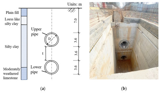
Figure 1.
Layout plan of Pipe jacking. (a) Vertical arrangement of the pipe jacking engineering and soil distribution; (b) Section view of vertical double-layer pipe jacking completed construction.
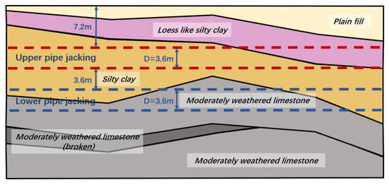
Figure 2.
Geological cross section of vertical double pipe jacking tunnel.
According to the survey report, silty clay is yellowish brown, plastic, contains a small amount of ferromanganese oxides, is locally intercalated with a small amount of ferromanganese nodules and occasionally crushed stones, has medium toughness, is slightly glossy and has a compression coefficient of 0.386. It is a medium compressible soil. Limestone is cyan gray, has an aphanitic structure, a layered structure, a rock core in short column shape to long column shape and a single block length of 20–60 cm; solution holes and corrosion cracks are seen on the rock surface in some sections and the joint fissures are filled with calcite veins and cohesive soil. The core recovery rate is 78–90%, the natural uniaxial compressive strength is 42.50–137.60 MPa and the average value is 85.58 MPa. Due to the large pipe section and high rock strength, the lower pipe jacking tunnel is constructed using a mud water balanced rock pipe jacking machine.
3. Numerical Method and Verification
3.1. Finite Element Model
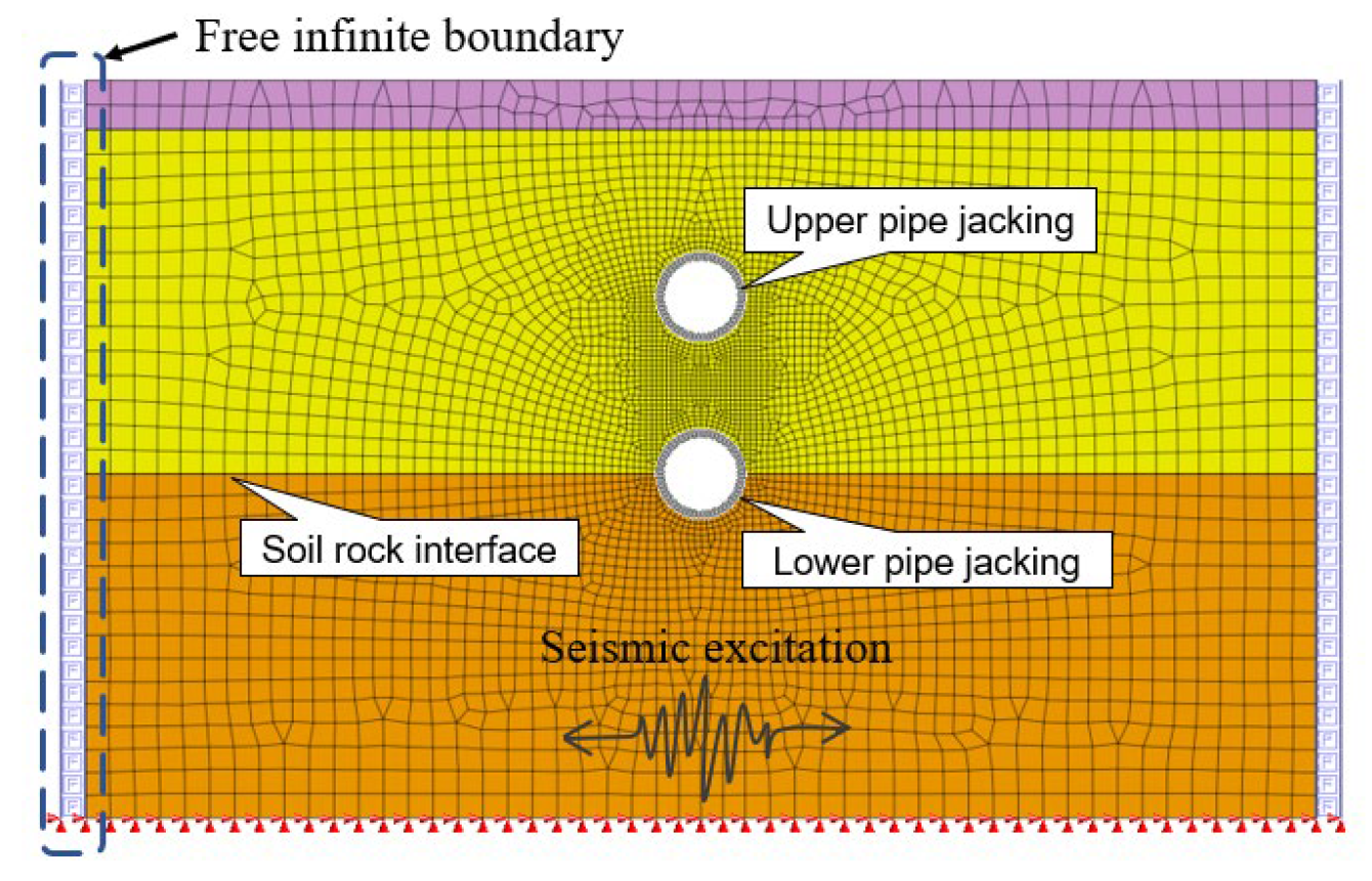
According to the typical soil–rock composite stratum in the Jinan area, the stratum is properly simplified to fill, silty clay and limestone. Considering the structure system of the soil–rock site and pipe jacking tunnel as a plane strain problem, the finite element software MIDAS/GTS was used to establish the model and make a grid division. In order to reduce the influence of the boundary effect on the dynamic response of the tunnel structure, the calculation area of the model is taken as 50 m × 30 m, that is the 3–5 times of structure size. In order to ensure the calculation accuracy and reduce the calculation time as much as possible, the grid division method of gradually densifying from the boundary to the vicinity of the pipe jacking is adopted. The maximum size of the grid is 1 m, which is less than 1/8 of the corresponding wavelength of the maximum wave frequency [17]. The pipe jacking structure adopts the 1D continuous beam element with equal stiffness, the soil and rock stratum adopts the 2D plane strain element and the finite element mesh division of the soil–rock-pipe jacking system is shown in Figure 3.
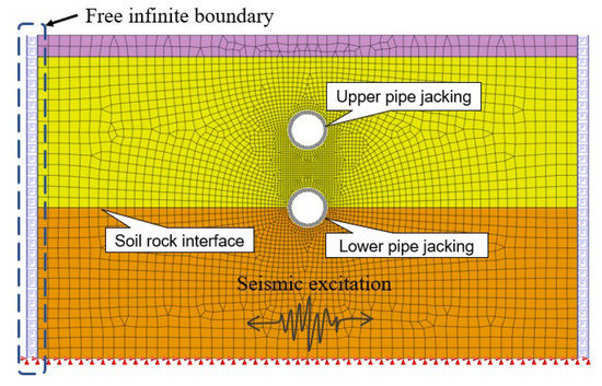
Figure 3.
Finite element model mesh of vertical double pipe tunnel in soil rock assemblage strata.
When the seismic wave propagates in the soil medium, the boundary of the model absorbs energy and rebounds part of it. This phenomenon will cause some errors to the overall analysis result of the finite element calculation. Therefore, the artificial boundary on the left and right sides of the finite element model adopts a two-dimensional free infinite element boundary to eliminate the reflection effect of the boundary. The upper boundary of the model is free surface and the lower rock boundary is fixed constraint.
The reinforced concrete pipe jacking structure adopts the linear elastic constitutive model, and the stratum adopts the Mohr–Coulomb constitutive model, without considering the separation and relative sliding between the soil and rock mass and the pipe jacking structure. The Mohr–Columb model is suitable for nonlinear, elastoplastic soil materials and has been widely used in geotechnical engineering. In the stress space, the yield surface of the Mohr–Columb condition is an irregular hexagonal cone, and the corresponding yield curve is a closed irregular hexagon in the plane π. The stress state of any point of the soil material should meet the following [18]:
From Mohr’s circle, it can be concluded that [18]:
The Mohr–Columb yield criterion can be rewritten as follows [18]:
The constitutive relationship of concrete material is a linear elastic model, which assumes that the stress and strain of the material are directly proportional to each other during loading and unloading and there is no residual deformation after complete unloading. The numerical calculation model considers both the self-weight and the earthquake motion. First, the stress field of the model under the dead weight is calculated, and then the response of the soil-pipe jacking structure under earthquake conditions is further calculated on the basis of the balance of the initial stress field. Rayleigh damping is used for calculation, and the empirical critical damping ratio is taken as 0.05.
3.2. Constitutive Model Parameters
The pipe jacking body is prefabricated in the factory with C50 high-strength concrete, which has the characteristics of high strength and small deformation. Therefore, the linear elastic constitutive model is adopted for the tunnel structure. In order to facilitate dynamic time history analysis, Mohr–Coulomb elastic–plastic constitutive model is adopted for plain fill, silty clay and limestone. Table 1 shows the calculation parameters of the dynamic finite element analysis.

Table 1.
Physical and mechanical parameters of materials.
3.3. Seismic Wave Input
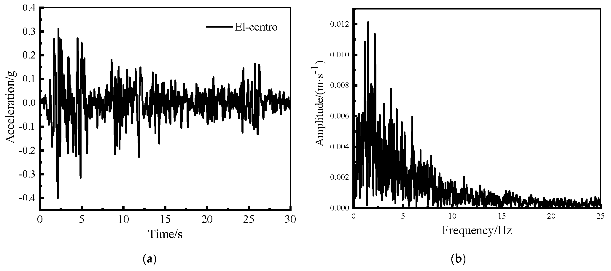
The time history analysis method is selected to analyze the seismic response characteristics of vertical double-layer overlapping pipe jacking. This method can accurately obtain the displacement, velocity, acceleration and internal force of each particle at different times under the action of seismic waves and reflect the direction, characteristics and continuous effect of ground motion. The surrounding rock of the tunnel site is moderately weathered limestone of grade IV, which belongs to a class II site in the code for seismic design of buildings [19]. The designed seismic group is group III, the site characteristic period is 0.45 s and the seismic fortification intensity is 6 degrees. However, as an important urban lifeline project, the seismic fortification should be increased by one degree and the designed basic seismic acceleration value is not less than 0.1 g. Based on Code for seismic design of urban rail transit structures [20] and Seismic ground motion parameter zonation map of China [21], the selected seismic wave should be close to the natural period of the site where the structure is located to increase the seismic response of the structure. El Centro wave was selected as the seismic wave input to the bedrock; its characteristic period is close to the design value of the tunnel site characteristic period, which satisfies the wave selection requirements of seismic waves. According to the seismic fortification standard of the Jinan area, the peak acceleration of ground motion is adjusted to 0.1 g, 0.2 g and 0.4 g, respectively, for calculation. Nevertheless, the spectral characteristics of the time history curve are unchanged.
The time history curve of the seismic wave band from 0 s to 20 s is selected for calculation. The damping ratio of all vibration modes is 0.05, the loading time is 20 s and the analysis time step is 0.02 s. A total of 1000 steps of calculation results are output. The seismic wave is inputted horizontally and transversely along the bedrock at the bottom; its acceleration time history and Fourier spectrum are shown in Figure 4.

Figure 4.
The acceleration time history and Fourier spectra of bedrock ground motion: (a) Time history curve of ground motion; (b) Fourier spectrum.
3.4. Verification of the Numerical Model
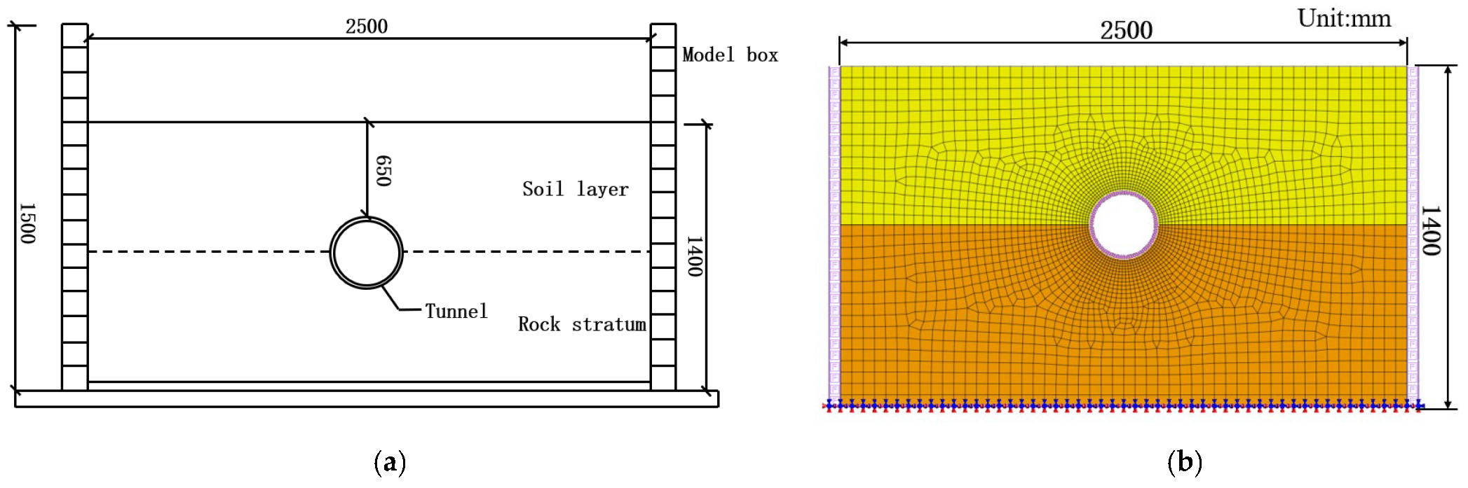
In order to verify the reliability of the above numerical method, a calculation model by the numerical method is firstly used to simulate the shield tunnel shaking table test [22]. The scale model experiment was conducted in the Structural Engineering Laboratory of Shandong Jianzhu University, as shown in Figure 5a. In this experiment, a multi-channel hydraulic servo drive is used to simulate control and the model box is a layered shear box. In the model experiment, gypsum and admixture were selected as the structural materials of the tunnel model and the soil layer was original silty clay. The hard rock model was prepared with quartz sand as the skeleton material, Portland cement and gypsum as the cementing material and was made by uniformly mixing and vibrating according to the mass ratio. The physical and mechanical parameters of the materials are obtained through the mechanical and geotechnical tests.
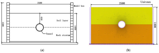
Figure 5.
Schematic Diagram of Shaking Table Test and Numerical Simulation: (a) Shaking table test; (b) Finite element model.
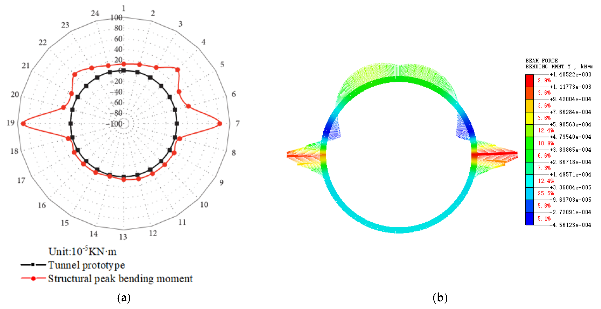
The finite element model of the shaking table test was established by using the numerical method adopted in this paper, as shown in Figure 5b. In order to make the seismic waves inputted by the numerical model consistent with the seismic waves inputted by the test, the acceleration time history record of the shaking table is used as the seismic excitation of the numerical model. Considering that there are many experimental conditions, some experimental conditions are selected for numerical simulation to compare experimental results and numerical calculation results. Due to the peak bending moment diagram of the tunnel structure obtained from the shaking table test (Figure 6a), we selected the peak bending moment diagram of the tunnel structure to compare the results. It is concluded that the change trend of the structural bending moment obtained from the numerical simulation and the model test is basically consistent, which proves that the calculation method and boundary conditions adopted by the numerical method are reliable and can be used for subsequent numerical research.

Figure 6.
Comparison of bending moment diagram between numerical simulation results and shaking table test results: (a) Shaking table test; (b) Finite element model.
4. Analysis of Numerical Calculation Results
4.1. Acceleration Response
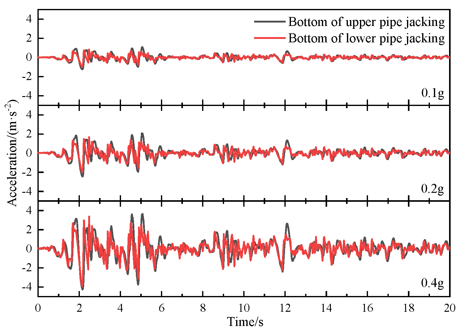
To investigate the seismic response of the double-layer pipe jacking structure under different ground motion intensities, the acceleration time history curves of the bottom of the upper and lower pipe jacking tunnels under the action of El Centro waves with three different peak accelerations are shown in Figure 7. It can be seen that:
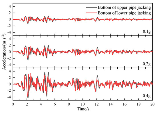
Figure 7.
Acceleration time history curves at the bottom of pipe jacking.
- (1)
- With the increase of the input peak acceleration from 0.1 g to 0.4 g, the ratio of the acceleration response peaks at the bottom of the upper and lower pipes is 1.31, 1.28 and 1.12, respectively. That is, the greater the peak acceleration, the smaller the acceleration amplification coefficient.
- (2)
- With the increase of the seismic motion, the peak accelerations at the bottom of the upper and lower pipes are increased and the peak acceleration of the upper pipe is greater than that of the lower pipe. This is related to the fact that the upper pipe is located in the soil and the lower pipe is semi-embedded in the rock layer. Therefore, due to the amplification effect of the soil layer and the embedment constraint of the underlying rock, it is more likely to cause serious damage to the pipe jacking structure in the soil–rock composite stratum.
4.2. Displacement Response
The soil layer lateral deformation induced by the earthquake exerted pressure on the underground structure, which will cause relative displacement of the underground structure itself, resulting in excessive internal force in the structure or dislocation of pipe joints and damage.
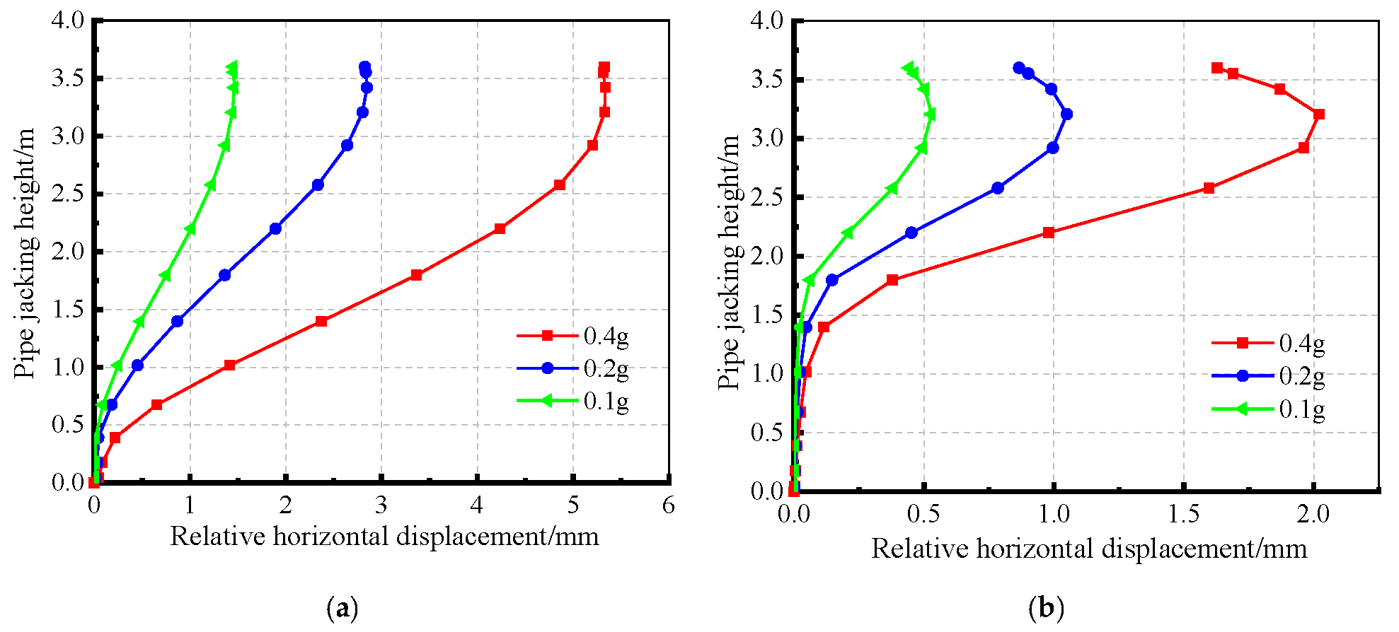
The circular tunnel deformation under earthquake conditions is generally an approximate ellipse symmetrical about the 45° axis [23]. In this study, take the horizontal displacement at the bottom of pipe as zero, the horizontal displacement at different heights of the pipe is obtained and the relative horizontal displacement curve is drawn. Figure 8 is the relative horizontal displacement curve of the upper and lower pipe jacking tunnels under different earthquake intensities.
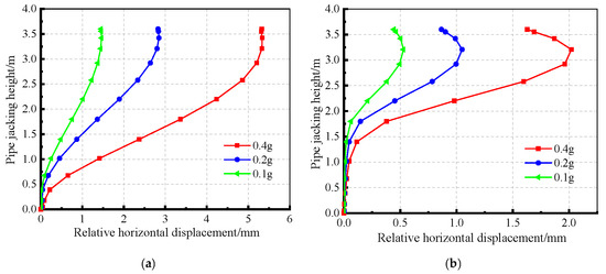
Figure 8.
Relative horizontal displacement distribution curves: (a) Upper pipe jacking tunnel; (b) Lower pipe jacking tunnel.
The following conclusions can be drawn:
- (1)
- The relative displacement curve of the upper pipe jacking structure presents an inverse S-shaped distribution and the maximum value of the relative displacement is located at the arch shoulder, which is basically located on the 45° symmetry axis of the pipe jacking and is consistent with the deformation of the circular tunnel. Meanwhile, the relative displacement of the upper part of the pipe does not continue to increase, which indicates that the soil deformation has less constrained effect on the top of the circular pipe jacking tunnel and the circular section is more conducive to resisting earthquake deformation.
- (2)
- The relative horizontal displacement curve of the lower pipe jacking tunnel along the height changes significantly. The displacement in the lower half of the pipe is basically constant, the maximum value is reached quickly and then the relative displacement decreases with the increase of the height, which is related to the larger deformation constraint effect due to the lower pipe being semi-embedded in the rock.
- (3)
- The relative horizontal displacement of the upper pipe jacking is more than twice that of the lower pipe jacking, which indicates that the closer to the ground, the larger the overall deformation of the underground structure. However, because the relative horizontal displacement in the soil–rock interface area changes sharply and the relative displacement curve in the upper soil layer is relatively gentle, this will lead to the pipe joints located in the lower soil rock stratum being more prone to deformation damage.
4.3. Stress Response
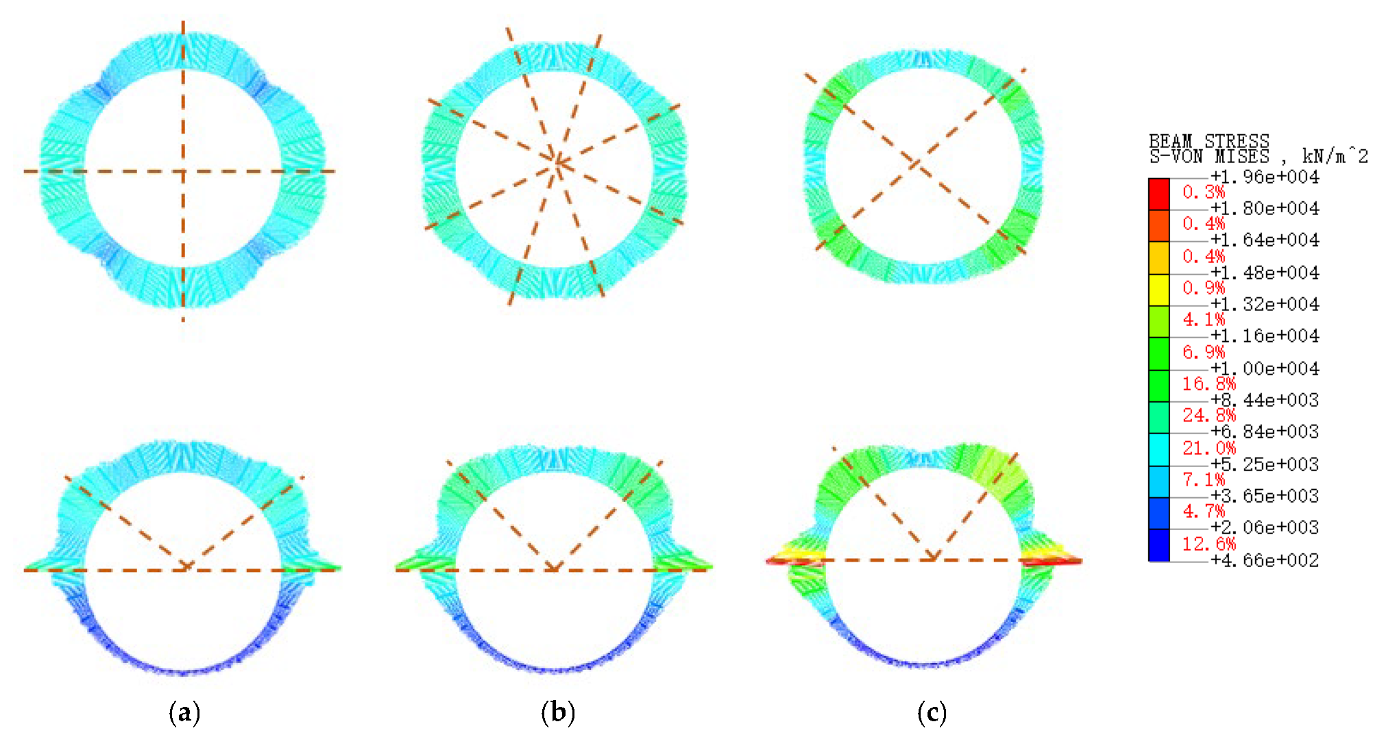
Figure 9 shows the cloud diagram of the maximum stress distribution of the vertical double-layer pipe jacking tunnel under the actions of different seismic motions. The following characteristics can be found:
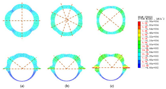
Figure 9.
Peak stress of the vertical double-layer pipe under different ground motions: (a) 0.1 g; (b) 0.2 g; (c) 0.4 g.
- (1)
- The upper pipe jacking is all located in the soil stratum, and the stress distribution is relatively uniform. When the peak acceleration of ground motion changed from 0.1 g to 0.4 g, the greatest stress positions and main stress axis gradually rotated about 45°, the stress distribution is relatively gentle and the failure risk of the pipe jacking tunnel in homogeneous soil stratum is low.
- (2)
- Under the three acceleration peaks of 0.1 g, 0.2 g and 0.4 g, the ratio of the maximum stress of the lower and upper pipe jacking is 1.32, 1.67 and 2.00, respectively. With the increase of the peak ground motion acceleration, the peak stress of the lower pipe jacking tunnel is uprushed in the soil–rock combination surface and the stress value is twice that of the upper pipe, meaning the lower pipe jacking tunnel more easily damaged.
- (3)
- The large stress areas are mainly at the soil–rock interface with obvious stress mutation. However, the stress is very small in the lower pipe embedded in the rock, indicating that the pipe jacking tunnel structures being all located in the stable rock is safer.
4.4. Interlayer Soil Response
In order to study the seismic response properties of interlayer soil between the upper and lower pipes, we keep the space position of the lower layer of pipe jacking fixed and the upper layer of pipe jacking moving up and down, four working conditions with different thicknesses of the soil interlayer are set, that is, t = 0.25 D, 0.5 D, 1.0 D and 1.5 D (t is the thickness of the soil interlayer and D is the outer diameter of the pipe jacking, which are shown in Figure 1b). The other parameters of the numerical model remain unchanged.
Figure 10 shows the distribution of the effective plastic strain of the soil between double-layer pipe jacking with different soil interlayer thicknesses. The plastic zone strain distribution reflects the stability of surrounding soil, which will induce pipe failure.
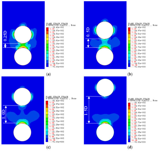
Figure 10.
Effective plastic strain distribution of soil between vertical double layer pipe jacking with different thickness of soil interlayer: (a) 0.25 D; (b) 0.5 D; (c) 1.0 D; (d) 1.5 D.
As the thickness of interlayer soil is reduced from 1.5 D to 0.25 D, the spacing ofpipe jacking is gradually reduced and the plastic area of the surrounding soil is continuously increased and connected into integration. The range of the plastic zone of the interlayer soil within the thickness of 0.25 D to 0.5 D is obviously connected as a whole, which causes the interlayer soil to be more vulnerable and further increases the horizontal and vertical displacement of the upper pipe. Finally, this will seriously damage the pipe. The heavier failure phenomena induced by the mutual effect of the upper and lower pipes can be defined as a small spacing earthquake failure effect. When the thickness of the interlayer soil is 1.0 D, the effective plastic strain areas around the pipe are relatively smaller and few are connected, which has no aggravating effect on pipe failure. When the the interlayer soil increases to 1.5 D, the obvious plastic zone range only appears in the lower tubular vault. The seismic response of the interlayer soil is no longer affected by the upper and lower pipes mutual effect.
Because the lower pipe jacking is semi-embedded in the rock, the plastic zone of the soil is mainly concentrated on the crown of the pipe jacking, which shows under the earthquake vibration the soil above the pipe will become loose and deformed, damaging the overall stability of the pipe jacking. Therefore, when the clear spacing is less than 1.0 D, some appropriate measures such as vault grouting should be taken to strengthen the arch soil within the range of 120° to resist earthquakes.
4.5. Influence of Soil–Rock Composite Stratum
In order to compare the influence of soil–rock stratum on the seismic response of double-layer pipe jacking, the lower rock stratum in Figure 3 is changed to silty clay and the other parameters are unchanged. Therefore, the calculation model of the double-layer pipe jacking tunnel is all located in the silty clay stratum. The seismic calculation with the peak acceleration of 0.4 g is carried out to find out the weak parts of the structure.
4.5.1. Site Frequency
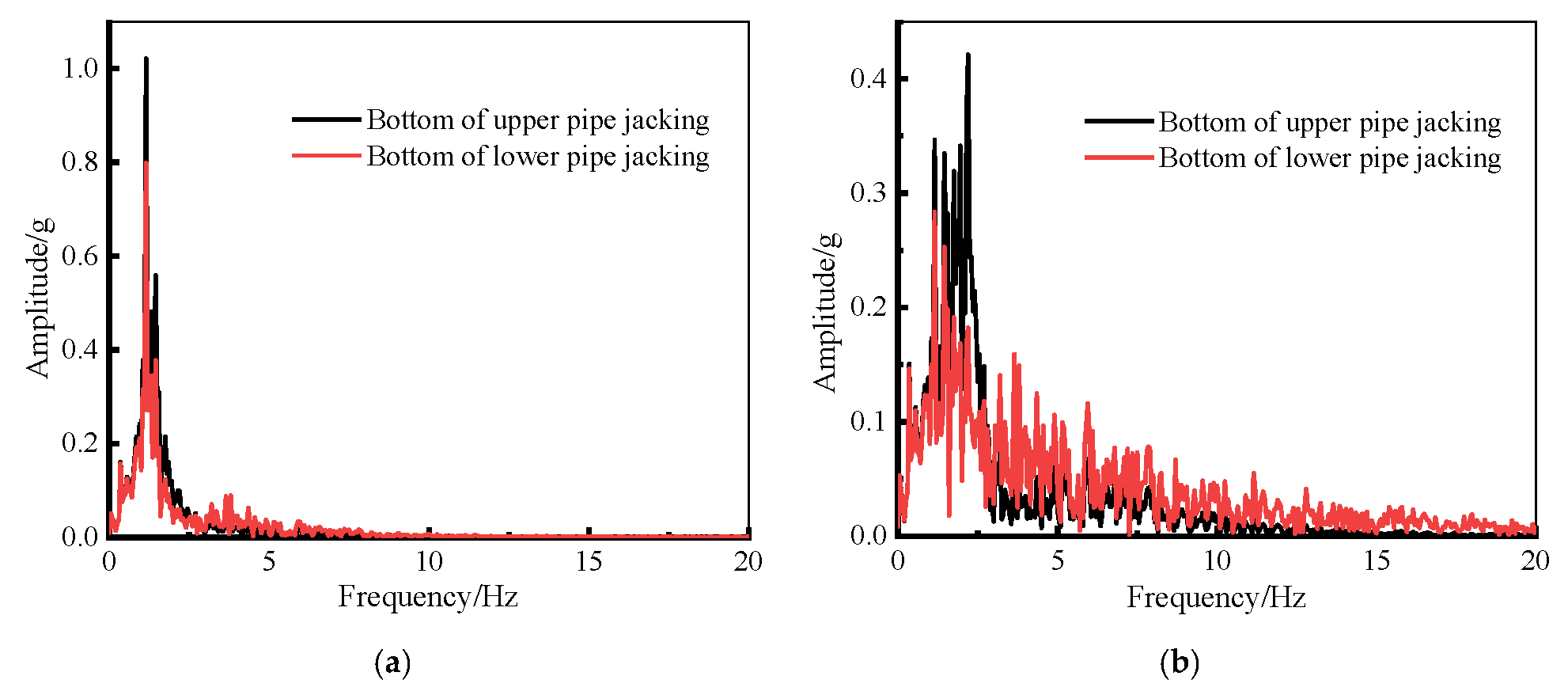
When the seismic wave propagates in the rock and soil medium, the site response spectral characteristics will change. The spectral characteristics have different effects on the underground structure with different natural vibration periods. Through time history analysis, the acceleration time history curves of the double pipe bottom are obtained. The fast Fourier transform (FFT) is carried out using SeismoSignal software, and the spectrum curves are shown in Figure 11.
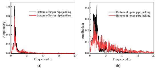
Figure 11.
Spectrum curves of the bottom of pipe jacking at different stratum: (a) Homogeneous silty clay stratum; (b) Soil–rock combination stratum.
As can be seen from Figure 11:
- (1)
- Under seismic action, the low-frequency components of the upper and lower pipe jackings are both gradually amplified and the high-frequency components are weakened, which conforms to the seismic response law of the formation.
- (2)
- In the homogeneous silty clay, the superior frequency distribution range of the pipe jacking tunnels is mainly 0.5–2.5 Hz and the influence range of ground motion in the homogeneous soil layer is relatively concentrated.
- (3)
- In the soil–rock combination stratum, the superior frequency distribution is in the range 0.5–10 Hz, which is more extensive than the homogeneous silty clay and is more likely to cause underground structural resonance and then cause vibration damage of the pipe jacking with different natural frequencies.
4.5.2. Pipe Jacking Structure Stress
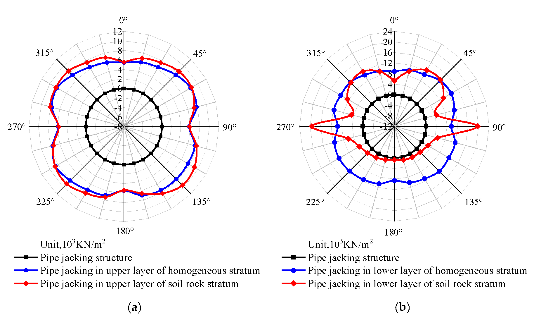
The polar coordinate distribution of peak stress was calculated, as shown in Figure 12. The stress of the upper and lower pipe jacking structures under two site conditions are compared and shown. It can be seen from the figure:
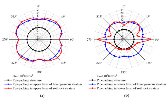
Figure 12.
Peak stress polar distribution of the pipe tunnel: (a) Upper pipe jacking; (b) Lower pipe jacking.
- (1)
- The upper pipe jacking under the two site conditions is located in the soil layer, and the stress distribution and stress value of the pipe jacking are basically the same. The maximum value is located on the 45° symmetry axis, and the minimum value is located on the horizontal and vertical symmetry lines. The ratio of the maximum and minimum stresses is about 1.6, which also indicates that the circular pipe jacking structure is prone to cracking along the 45° symmetry axis.
- (2)
- The stress of the lower and upper pipe jackings in homogeneous stratum is basically the same distribution form, and the maximum stress is basically located at the 45° symmetry axis. The stress value of the lower pipe is about 1.5 times that of upper pipe due to the lower pipe being subjected to greater earth pressure.
- (3)
- Due to the large difference in the stiffness of soil and rock, the seismic wave at the soil–rock junction transmitted and reflected may form a certain seismic surface wave effect [24,25]. The stress at the soil–rock interface, with an increase of 104% compared with the homogeneous soil stratum, and the stress distribution pattern of the lower pipe jacking under the two site conditions is quite different too. Therefore, the seismic energy acting on the pipe jacking structure increases at the soil–rock interface, which is more likely to cause the pipe jacking tunnel damage.
5. Conclusions
By using MIDAS/GTS software and the nonlinear dynamic time history calculation method, the seismic response characteristics of large diameter vertical double-layer pipe jacking in soil–rock combination sites have been numerically analyzed and studied. The main conclusions are as follows:
- (1)
- With the differential seismic motion input, the acceleration response of the upper tube is 1.1–1.3 times for the lower tube and the horizontal displacement value is more than 2 times. Nevertheless, the relative horizontal displacement of the lower tube changed sharply in the soil–rock interface, which is more likely to cause serious damage to the pipe in the soil–rock composite stratum.
- (2)
- The superior frequency range of the Fourier spectrum at the soil–rock composite stratum is wider than that of all homogeneous soil layers and easily causes vibration damage to pipe jacking structures with different natural frequencies. Moreover, the stress increase of the arch waist part in the lower soil–rock combination stratum is 104% compared with the homogeneous stratum, and the failure of the pipe jacking structure will further aggravate if the soil rock interface fluctuates longitudinally.
- (3)
- The smaller the thickness of the interlayer soil layer between the upper and lower pipes, the larger connected as a whole of the plastic zone and the more likely damage to the overall stability of pipe jacking in soil–rock combination stratum is. When the small spacing earthquake failure effect cannot be neglected, appropriate measures should be taken to strengthen the interlayer soil strength to resist earthquakes.
Author Contributions
Conceptualization, G.S. and J.H.; methodology, L.D.; software, L.D.; validation, G.S., J.S. and J.H.; formal analysis, G.S. and L.D.; investigation, G.S.; resources, J.S.; data curation, L.D.; writing—original draft preparation, L.D.; writing—review and editing, G.S. and J.H.; visualization, G.S.; supervision, G.S.; project administration, J.H.; funding acquisition, J.S. All authors have read and agreed to the published version of the manuscript.
Funding
This research was funded by Key Program of National Natural Science Foundation of China, grant number 52038006 and Innovation Team Development Program of the Ministry of Education, grant number IRT_17R69.
Institutional Review Board Statement
Not applicable.
Informed Consent Statement
Not applicable.
Data Availability Statement
The data are contained within the article.
Acknowledgments
We are grateful to the Jinan Rail Transit Group Co., Ltd. for providing us with the experimental project.
Conflicts of Interest
The authors declare no conflict of interest.
References
- An, G.F.; Wang, T.; Si, H.F.; Liu, T.J. Influence of construction sequence and different types of pipes on ground surface settlement caused by the construction of two-layer jacking-pipes. Mod. Tunn. Technol. 2019, 56, 119–126. [Google Scholar]
- Yang, J.H.; Chen, W.B.; Zhang, L.; Xu, X.C.; Cheng, L.Y. Research on varying regularity of soil vertical deformation caused by the construction of two-layer jacking-pipe. Sci. Technol. Eng. 2014, 14, 274–279. [Google Scholar]
- Wang, Z.Z.; Zhang, Z. Seismic damage classification and risk assessment of mountain tunnels with a validation for the 2008 Wenchuan earthquake. Soil Dyn. Earthq. Eng. 2013, 45, 45–55. [Google Scholar] [CrossRef]
- Chen, W.Z.; Song, W.P.; Zhao, W.S.; Yang, D.S.; Zhao, K.; Sheng, Q. Research progress of underground engineering seismic analysis methods and performance evaluation. Chin. J. Rock Mech. Eng. 2017, 36, 310–325. [Google Scholar]
- Cui, G.Y.; Song, B.H.; Wang, D.Y.; Xiao, J. Model test of seismic behavior of fiber concrete lining at the interface between soft and hard surrounding rock of tunnel. Chin. J. Rock Mech. Eng. 2021, 40, 2653–2661. [Google Scholar]
- Chen, L.; Chen, G.X. Seismic response of double-layer vertical overlapping subway tunnel under strong ground motion near fault. J. Disaster Prev. Mitig. Eng. 2008, 4, 399–408. [Google Scholar]
- Chen, L.; Chen, G.X.; Li, L.M. Seismic response characteristics of double-layer vertical overlapping subway tunnel subjected to near-field and far-field vibrations. China Railw. Sci. 2010, 31, 79–86. [Google Scholar]
- Yang, N.B. Analysis of the Earthquake Reaction and Influencing Factors of the Shield Tunnel; Institute of Engineering Mechanics: Harbin, China, 2013. [Google Scholar]
- Zhang, W.J.; Yuan, D.J. Earthquake Research and Examples of Shield Tunnel; China Architecture & Building Press: Beijing, China, 2009. [Google Scholar]
- Yu, Y.S. Analysis of the Power Response of the Shield Tunnel under the Strong Earthquake; Dalian University of Technology: Dalian, China, 2015. [Google Scholar]
- Yin, Y.T.; Li, T.C. Earthquake damage mechanism analysis and aseismic study of tunnel structure with soft and hard interface of soil and rock. Mod. Tunn. Technol. 2013, 50, 84–91. [Google Scholar]
- Wang, W. Study on the Characteristics of the Earthquake Response Characteristics of Soft and Hard Mutations on the Earth Shield Tunnel; Southwest Jiaotong University: Sichuan, China, 2015. [Google Scholar]
- Zhang, J.; He, C.; Geng, P.; He, Y.; Wang, W.; Meng, L. Shaking table test of longitudinal seismic response of shield tunnel passing through soft and hard abrupt strata. Chin. J. Rock Mech. Eng. 2017, 36, 68–77. [Google Scholar]
- Liang, J.W.; Xu, A.Q.; Ba, Z.N.; Chen, R.D.; Zhang, W.; Liu, M.G. Shaking table test and numerical simulation on ultra-large diameter shield tunnel passing through soft-hard stratum. Soil Dyn. Earthq. Eng. 2021, 2021, 106790. [Google Scholar] [CrossRef]
- Cui, G.Y.; Ma, J.F. Shaking table test on the seismic response of the portal section in soft and hard rock junction. Sci. Prog. 2021, 103, 1–15. [Google Scholar] [CrossRef] [PubMed]
- Wang, S.H.; Gao, B.; Wang, Y.X.; Yang, X.; Teng, Z.N. Analysis and research on dynamic response law and seismic measures of mountain tunnel in high intensity earthquake region. Mod. Tunn. Technol. 2013, 50, 60–67. [Google Scholar]
- Kuhlemeyer, R.L.; Lysmer, J. Finite element method accuracy for wave propagation problems. J. Soil Mech. Found. Div. 1973, 99, 421–427. [Google Scholar] [CrossRef]
- GTS NX. General Geotechnical Finite Element Software Theoretical Analysis Manual; Beijing Midas Co., Ltd.: Beijing, China, 2015. [Google Scholar]
- Huang, S.M.; Wang, Y.Y. Code for Seismic Design of Buildings, GB50011-2010; China Architecture and Building Press: Beijing, China, 2016; pp. 18–20. [Google Scholar]
- GB50909-2014; Code for Seismic Design of Urban Rail Transit Structures. Standards Press of China: Beijing, China, 2014.
- GB18306-2015; Seismic Ground Motion Parameter Zonation Map of China. Standards Press of China: Beijing, China, 2015.
- Shao, G.B.; Fan, X.S.; Shang, J.H.; Lu, L.X. Study on seismic response characteristics of shield tunnel in soil-rock combination stratum. Adv. Civ. Eng. 2022, 2022, 7504347. [Google Scholar] [CrossRef]
- Chen, L.; Chen, G.X.; Chen, S. 3D Nonlinear Seismic Response Analysis of Intersecting MetroTunnels Under Far-Field Ground Motion of Large Earthquake. Low-carbon economy and civil engineering science and technology innovation—2011 China (Beijing) International Architectural Science and Technology Conference Paper III. In Proceedings of the 10th International Conference on Contemporary Problems of Architecture and Construction, Beijing, China, 23 September 2010. [Google Scholar]
- Li, T.C.; Yin, Y.T. Seismic damage analysis of tunnel structure in Wenchuan earthquake. Eng. Blasting 2011, 17, 24–27. [Google Scholar]
- Shen, Y.S.; Zou, C.L.; Jin, Z.Z.; Wang, J.W. A Study of the Dynamic Response Characteristics of a Tunnel Structure Through an Interface of Soft and Hard Rock. Mod. Tunn. Technol. 2015, 52, 95–102. [Google Scholar]


Disclaimer/Publisher’s Note: The statements, opinions and data contained in all publications are solely those of the individual author(s) and contributor(s) and not of MDPI and/or the editor(s). MDPI and/or the editor(s) disclaim responsibility for any injury to people or property resulting from any ideas, methods, instructions or products referred to in the content. |
© 2023 by the authors. Licensee MDPI, Basel, Switzerland. This article is an open access article distributed under the terms and conditions of the Creative Commons Attribution (CC BY) license (https://creativecommons.org/licenses/by/4.0/).