1. Introduction
Landing gears are an important source of aircraft noise at approach and landing, which has motivated a significant amount of research on their noise [
1,
2,
3]. A number of the studies have been concerned with comparing acoustic results for landing gears of different scales and geometric fidelity.
A classic work on the topic was published by Heller and Dobrzynski [
4], who compared the noise of small-scale models of landing gears with the results of flight tests. The small-scale landing gears had a generic geometry, which was different from the landing gears of the aircraft (Jetstar, BAC 111, HS 125, and VC 10) in flight tests. Nevertheless, the comparison was generally favorable, although there were discrepancies in the normalized noise spectra for four-wheel landing gears. A possible explanation of these discrepancies was proposed by Crighton [
1], who noticed that the noise spectra for the flight tests with four-wheel landing gears were considered in [
4] for the gear bay doors closed, while the small-scale tests were carried out with an open wheel well. If the small-scale data are compared with the flight tests with open doors, the normalized noise spectra demonstrate a much better agreement.
Later, Hayes et al., performed a study [
5] where a small-scale (4.6%) model of a DC-10 wing with a simplified main landing gear was investigated. The small-scale tests showed that the landing gear had a negligible effect on the airframe noise, which contradicted the flight tests where the effect of landing gear on measured noise was significant. Continuation of the work for a 6.3% wing model with simplified and detailed main landing gears of a B777 led to the important observation [
6] that for higher frequencies the noise of the detailed landing gear model is higher than for the simplified one. This effect was then demonstrated for simplified and detailed 26% models of isolated main landing gears of the B777 [
7], as well as main landing gears on the 26% wing model [
8,
9]. A comparison for the 6.3% high-fidelity main landing gear model with B777 flight tests was provided in [
10,
11], demonstrating a rather good agreement, despite significant scatter in the flight test data. The scatter often appears in flight tests results due to the uncontrolled environment of the experiment; therefore, it is important to perform full-scale experiments in the controlled environment of large anechoic facilities.
Indeed, a new era of experimental research has begun with the acoustic measurements of full-scale landing gears in anechoic conditions. In [
12,
13] such tests were performed for A320 and A340 landing gears, with a view on developing noise reduction technologies. A study on the full-scale B737 main landing gear with modifications and simplifications is provided in [
14]; this work compares high-fidelity and low-fidelity full-scale landing gear models. A similar work was recently performed under the ALLEGRA project [
15] for a full-scale nose landing gear model and in [
16] for a 16.7% nose landing gear model of B777.
A comparison of full-scale and smaller-scale (25%) main landing gear models of A340 is reported in [
17,
18], where both the appearance of tones and broadband noise spectra were considered. The spectra for landing gear models were found to be in a good agreement, except for higher frequencies, which was explained by simplifications of fine details for the 25% model.
Noise results for an 18% wing model with a main landing gear, a full-scale model landing gear and flight tests are compared in [
19]. Full-scale tests and flight tests give rise to similar noise spectra, whereas 18% model tests turned out to provide lower noise levels. Novel tests with the 18% model are reported in [
20], where the agreement with full-scale and flight tests was improved, although discrepancies both in low-frequency and high-frequency parts of noise spectra were still observed. These small-scale landing gear models had slightly different geometry than full-scale landing gear and did not reproduce fine elements of the full-scale model.
This brief literature review demonstrates that noise results for small-scale and larger-scale landing gear models are typically determined for the models, which have different geometries (mostly with respect to fine details). Indeed, large-scale tests are expensive and are typically performed in the interests of the industry; therefore, they tend to use the most realistic models of landing gears or even real landing gears. At the same time, small-scale models do not exactly reproduce some details of the complex large-scale landing gears, thus simplifying their original geometry.
However, this poses the question of whether the differences in acoustic results are due to the differences in geometries or due to other reasons such as the Reynolds number effect, different scaling laws, or experimental errors. Therefore, it is important to isolate one of the effects to study its influence on noise spectra.
This paper aims at isolating the effect of landing gear geometry on its noise by considering full-scale and small-scale landing gear models with identical simplified geometry that differ only in their scale. The tests of the small-scale generic landing gear were performed in an anechoic chamber with flow AC-2 TsAGI (Moscow, Russia), whereas the large-scale landing gear models were tested in a large anechoic facility FL-17 CARDC (Mianyang, China).
In these tests, the large-scale landing gear models had simplified geometries and lacked small geometric details, which for the first time allowed their results to be directly compared with those for the small-scale models of the same geometry. It seems that this study of the geometry effect, where the landing gear models of different scales have identical geometry, is novel in its approach; the authors are not aware of such studies published in the open literature.
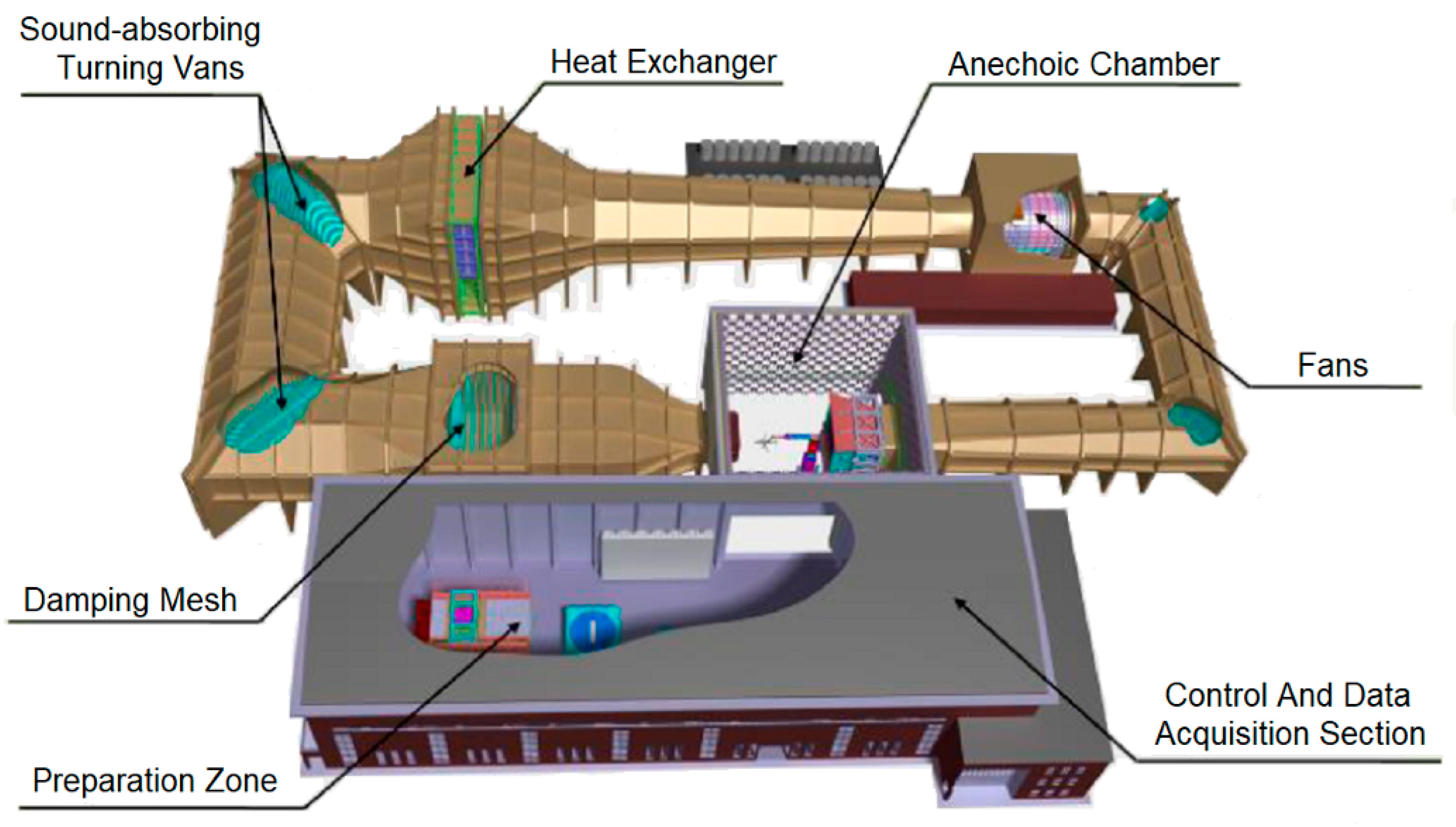
The paper is organized as follows. In the next Section, a brief description of anechoic facilities FL-17 CARDC and AC-2 TsAGI is provided.
Section 3 describes the landing gear models that were tested in these facilities.
Section 4 describes experimental corrections applied to the measured data in both facilities. Then, the comparison of the experimental results is performed in
Section 5, and some conclusions regarding the scaling of the results of small-scale tests to the full scale are made.
3. Landing Gear Models
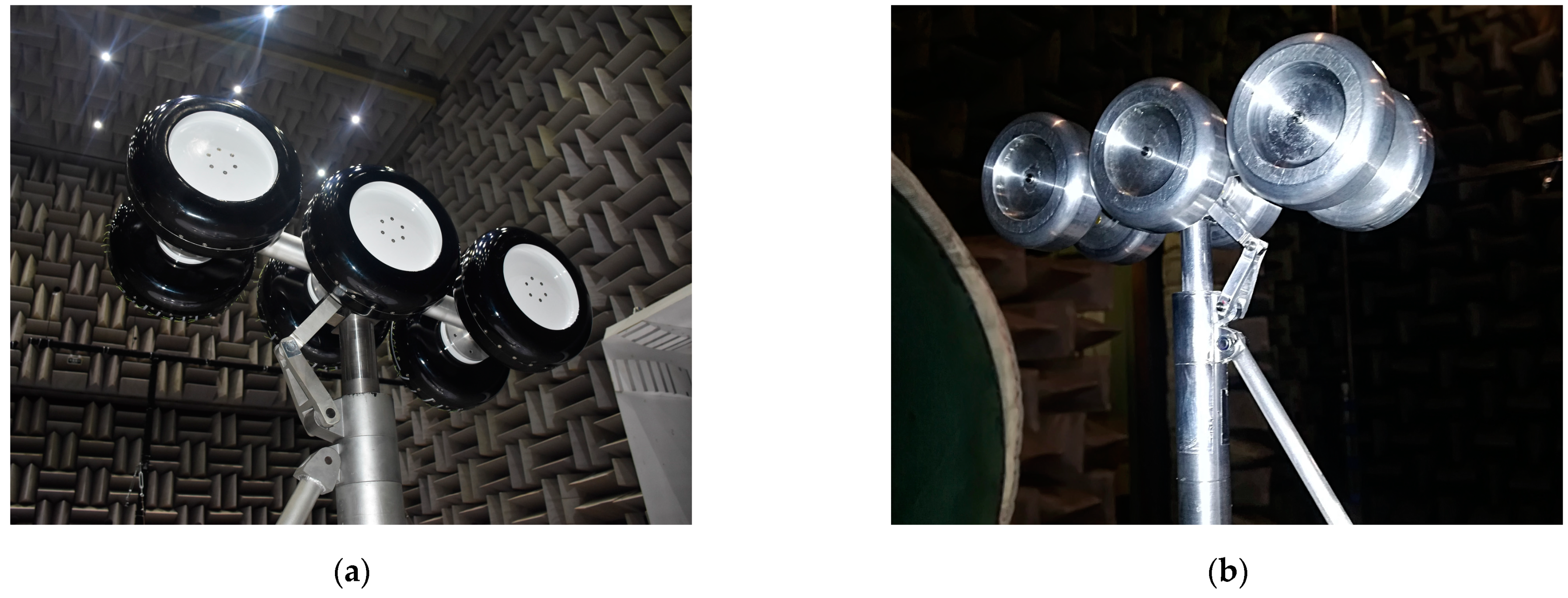
As described in the introduction, the major objective of this study consists of comparing noise measurements for landing gear models that have the identical generic geometry but different scales. As an example, photos of large-scale and small-scale landing gear models are shown in
Figure 6. The small-scale landing gear models studied in AC-2 TsAGI have the same geometry as the large-scale models, but their scale with respect to the models from FL-17 CARDC is 1:10.9 (
Figure 7).
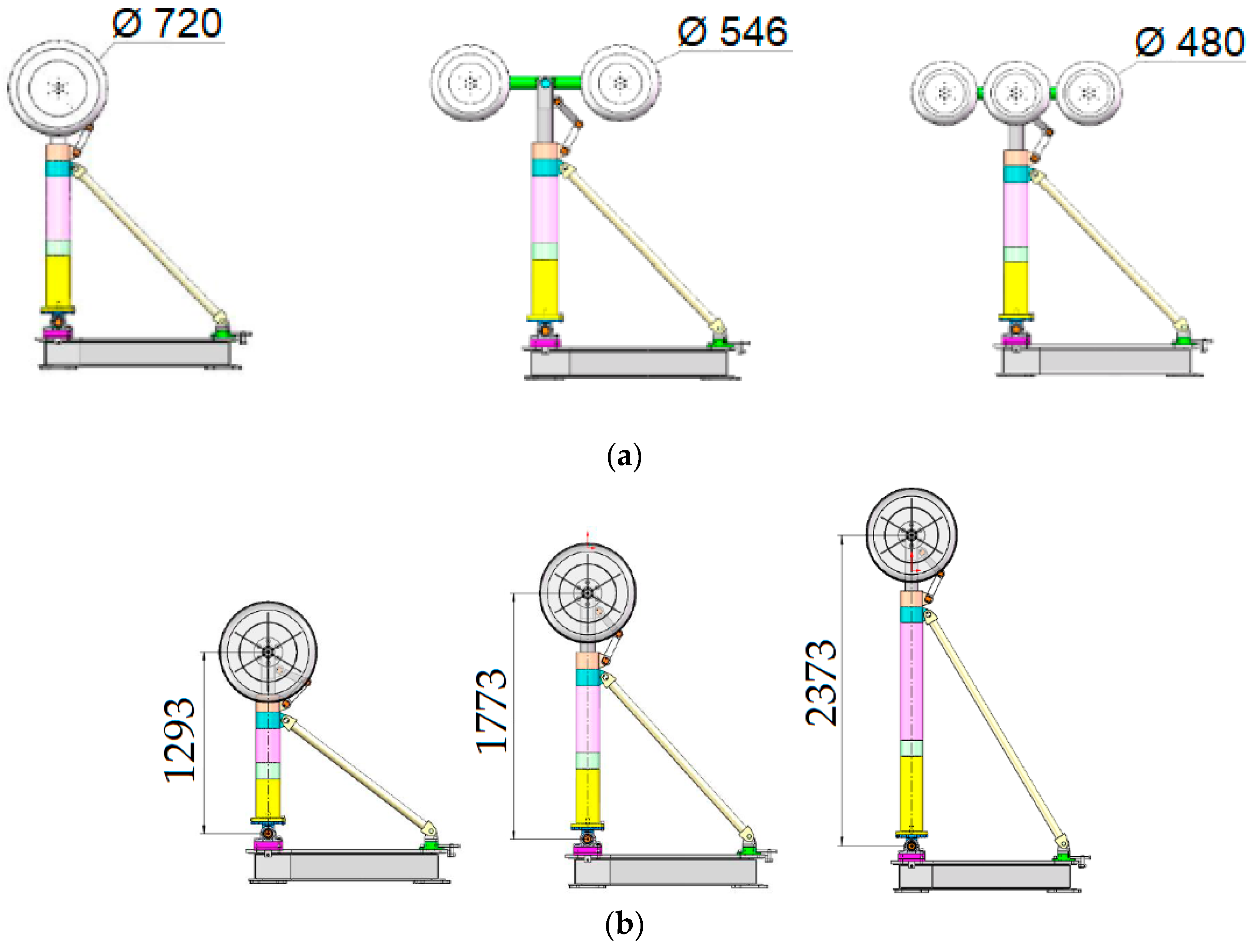
Landing gear models for both small-scale and full-scale tests were designed and manufactured as modular constructions, which allowed installation and removing some parts of the landing gear model, such as the wheels, the torque link, and the main leg (shock strut), as well as changing the geometric parameters of the model (number and diameter of the wheels, height of the main leg, inclination angle of the wheel track, etc.).
Figure 8a shows schemes of full-scale landing gear models with different numbers of wheels, whereas different main leg heights are depicted in
Figure 8b. Such a construction allows comparing acoustic results for small-scale and full-scale landing gear models for an extensive range of geometric parameters.
However, before the test results from the different facilities can be compared, their data quality must be checked, and a number of corrections must be applied to the experimental results. These corrections are described in the next section.
4. Data Quality Checks and Experimental Corrections
Before comparing the noise results obtained in these two anechoic facilities, a number of corrections should be applied to the data measured with the out-of-flow microphones to determine the acoustic characteristics of the noise source. In particular, sound pressure levels have to be corrected for insufficient signal-to-noise ratio, the effects of shear-layer refraction, atmospheric absorption, and geometric distance. These corrections were performed as follows:
Background noise correction
Correction for shear-layer refraction
Correction for microphone directivity and frequency response
Atmospheric absorption
Geometric position (for AC-2 TsAGI data)
Strouhal scaling (for AC-2 TsAGI data)
4.1. Background Noise Correction
Background noise correction consisted of subtraction of the narrowband spectra of background noise
LBG (i.e., noise when the landing gear model is removed) from the narrowband spectra of landing gear noise
LLG according to Equation (1). If the level difference
L between the total noise and the background noise is less than 3 dB, then the correction can be considered as introducing too-large errors, so that the source level cannot be determined.
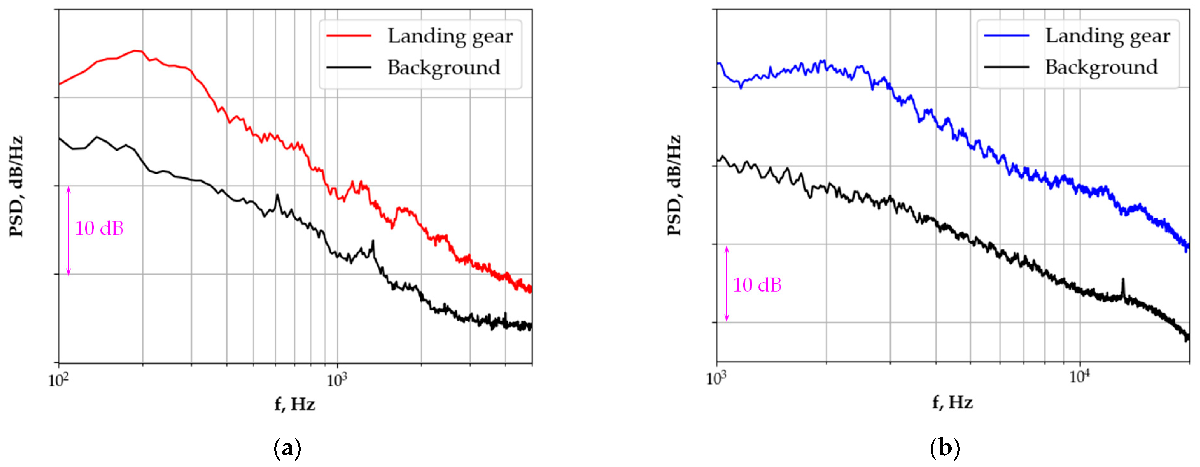
To compare noise spectra, the acoustic signal measured over a time interval of 30 s at a sampling frequency of 51,200 Hz is separated into Hanning-widowed blocks with 66.7% overlap, corresponding to a bandwidth of 3.125 Hz. After Fast Fourier Transform (FFT), the final spectrum is averaged over 280 blocks to smooth the curve. All the spectra displayed in this paper show the power spectral density (PSD) in dB/Hz (rel. to 2 10−5 Pa).
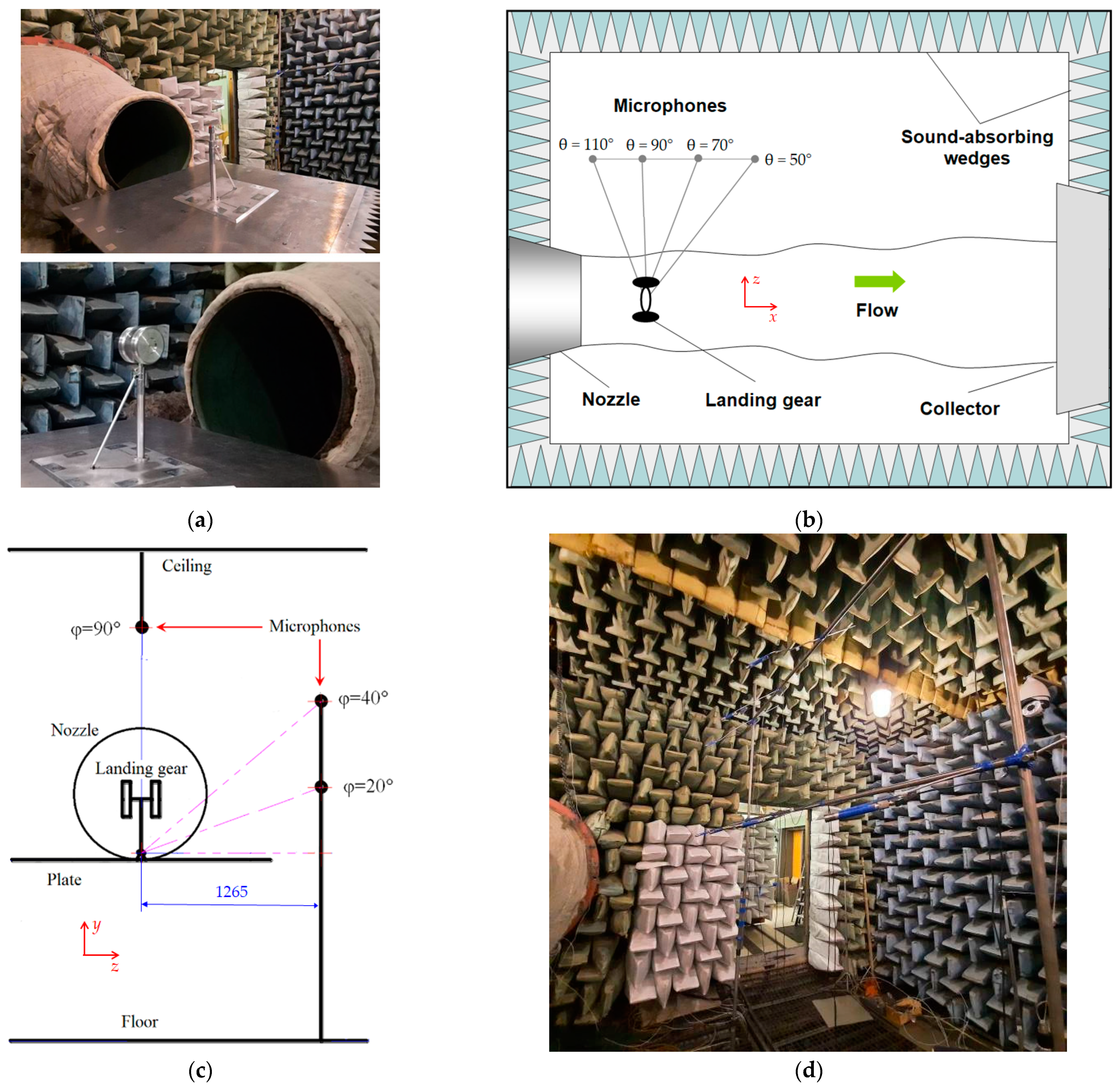
Figure 9 shows a comparison of the background noise and landing gear noise for both facilities when the flow velocity is 75 m s
−1; the landing gear model is the four-wheel model with the high main leg (
Figure 5b) and microphone position (θ, φ) = (90°, 20°).
From
Figure 9, it can be seen that for the full-scale model the landing gear noise exceeds the background noise by at least 3 dB in the frequency range below 10 kHz, whereas for small-scale models the landing gear noise becomes noticeable over the background noise only for frequencies more than 400 Hz.
It is worth noting that a strong tone is present at 840 Hz for the small-scale landing gear model, whereas no such tone is observed for the full-scale model. It is likely that this tone is an Aeolian tone produced by the main leg of the landing gear model; its Strouhal number St calculated based on the main leg diameter d = 16.9 mm for frequency f = 840 Hz and flow speed V = 75 m s−1 is St = f d/V = 0.19, which is close to the expected value of St = 0.2 for such a tone. The peak is absent from the noise spectra of the full-scale model, because its frequency at the full scale would be ~77 Hz, i.e., it is below the low-frequency limit of FL-17 CARDC and is not visible in the spectra.
The spectra in
Figure 9 are shown for the whole frequency range from 100 Hz to 20 kHz. However, from the perspective of the spectra comparison, only a part of this frequency range is of interest. Indeed, after Strouhal scaling for the scale
l = 10.9 the data from AC-2 TsAGI will be located in the frequency range below 2 kHz, so the higher frequency part of the spectra from FL-17 CARDC cannot be directly compared with AC-2 TsAGI results. Therefore, in the following analysis the highest frequency of FL-17 CARDC data will be limited to 5 kHz. On the other hand, the low-frequency limit of FL-17 CARDC facility is 100 Hz, which implies that only the part of the noise spectra from AC-2 TsAGI with frequencies above 1 kHz can be directly compared with FL-17 CARDC data. As a result, the high level of the background noise at low frequencies in AC-2 TsAGI will not affect the comparison of the spectra with FL-17 CARDC data. The tone at 840 Hz for the small-scale model (
Figure 9b) will also be excluded from the full-scale frequency range, after the noise spectra for the small-scale model are scaled to the full scale based on the Strouhal number.
Figure 10 shows the parts of the noise spectra from
Figure 9 that are used for comparison of small-scale and full-scale noise data.
4.2. Shear Layer Correction
If a sound source is placed in the wind tunnel core flow, and the measuring microphones are placed outside it, the sound waves have to pass through the shear-layer separating the open jet from the ambient air. This leads to a change in propagation direction (apparent radiation angle) and amplitude of the sound waves. In addition, the sound waves are convected downstream while propagating in the flow. To account for these effects, the data must be corrected. In this study, a widely used scheme from Amiet [
23] to correct for shear-layer refraction is applied to the measurement data. The scheme allows for correction for both planar and circular shear layer, which correspond to the FL-17 CARDC and AC-2 TsAGI facilities, respectively. The shear-layer corrections depend on the measurement geometry (the incidence angle at the shear layer, in particular) and on flow velocity, but not on sound frequency.
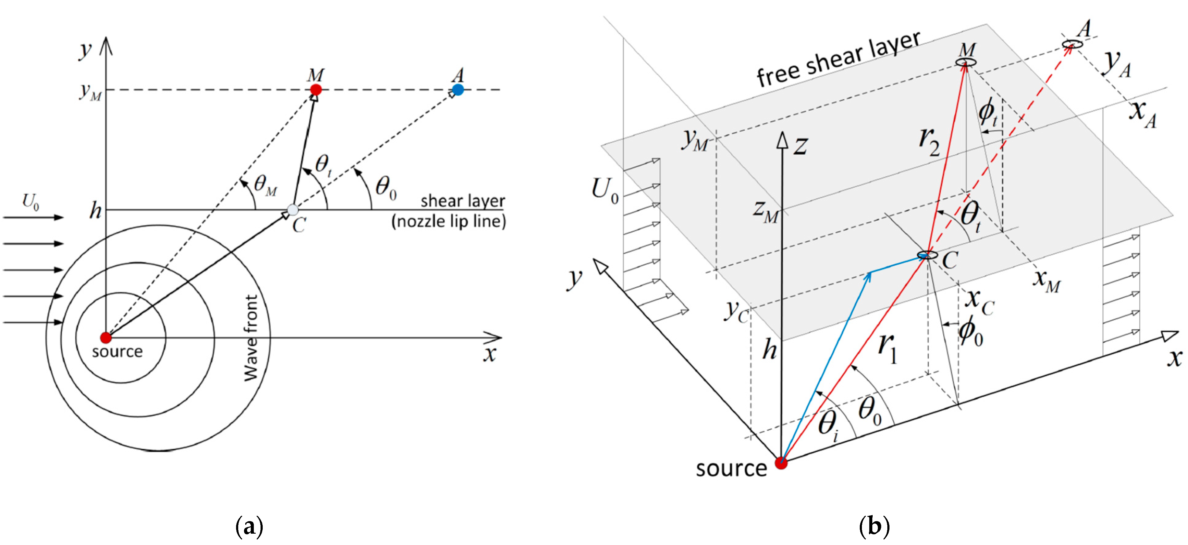
The geometry and notations of the shear layer correction are shown in
Figure 11. Two-dimensional geometry (
Figure 11a) corresponds to either the case of a cylindrical shear layer with the source located at the centerline or the case of a plane shear layer with the source and the microphone located in the x–z plane. The case of a plane shear layer with the source and the observer not in this plane corresponds to three-dimensional geometry (
Figure 11b).
The azimuthal and polar angles described in
Section 2 are measured from the junction point of the landing gear with the support system. However, localization of the noise sources with the beamforming method [
24] and numerical simulation [
25] suggest that the major noise sources of the landing gears comprise wheels, torque link, and strut. Therefore, the upper point of the main leg will be considered as the position of the source, which should better correspond to the physics of the problem, although it has an obvious drawback that the polar angle of the microphones will be different for landing gears with different main leg heights. For instance, for the landing gear model with a high main leg in FL-17 CARDC polar angle φ = 20° becomes φ
M = –1.9°, while polar angle φ = 40° becomes φ
M = 24.8°.
A comparison of the results for radiation angles (θ
0, φ
0) obtained for the plane shear layer in FL-17 CARDC with 2D and 3D approaches is provided in
Table 1. The polar angle φ
0 for the 2D correction procedure is 0° by definition. It can be seen that both methods provide close values of azimuthal angles θ
0, and for φ = 20° the values of polar angles φ
0 are also quite similar. Taking into account the uncertainties associated with the position of the noise source, it has been concluded that the 2D correction procedure can be used for shear layer refraction in FL-17 CARDC.
Similarly, a comparison of the results obtained with the 2D correction procedure for radiation angle θ
0 in FL-17 (plane shear layer) and AC-2 (cylindrical shear layer) is provided in
Table 2. It can be seen that although geometrical positions of the microphones in AC-2 TsAGI and FL-17 CARDC were chosen as close to each other as possible, the shear layer correction introduces some differences in radiation angles between the two facilities, which will be accounted for in the further analysis.
In addition to the angle correction, the shear layer correction procedure also introduces amplitude corrections, which differ between the plane and cylindrical shear layer [
23]. The resulting values correspond to the measurements of the landing gear noise by inflow microphones at the angle θ
0 (rather than θ).
4.3. Correction for Microphone Directivity and Frequency Response
The experimental data were then corrected to account for the characteristics of microphones, such as microphone directivity (for the actual incident angle determined by θt) and frequency response. The characteristics are provided by the manufacturer.
4.4. Atmospheric Absorption
Noise data are corrected for atmospheric absorption following the procedure developed by Sutherland [
26] and based on the true radiation angles and distances as determined by the shear layer refraction correction.
4.5. Geometric Position (for AC-2 TsAGI Data)
Although geometric positions of the microphones in AC-2 TsAGI and FL-17 CARDC were deliberately chosen as close to each other as possible, distances from the landing gear to the microphones in AC-2 TsAGI and FL-17 CARDC differ, as can be seen from
Figure 2b and
Figure 4c. The data from AC-2 TsAGI are therefore corrected to the distances of FL-17 CARDC using the geometric spreading law.
Moreover, the shear layer reflection introduces some differences in radiation angles between the two facilities. To account for the difference in radiation angles, the noise level of the results from AC-2 TsAGI are interpolated with respect to azimuthal angle for each frequency, which allows the interpolated spectra to be obtained at azimuthal angles θ
0, corresponding not to the values of AC-2 but to the values of FL-17. An example of such an interpolation is provided in
Figure 12.
As a result of the procedure, noise levels of small-scale landing gears are determined in the position and distances corresponding to the microphones in FL-17.
4.6. Strouhal Scaling (for AC-2 TsAGI Data)
The resulting noise spectra correspond to landing gear noise measured for small-scale and large-scale models in the same conditions. Then, the AC-2 TsAGI data are transferred to the full scale, thus allowing the results from the two facilities to be directly compared. Since the flow speeds
V in both facilities were the same, there was no problem of spectra scaling with respect to flow speed as the 6th or 7th power of
V (or something else), which has been extensively discussed in a number of studies on landing gear noise [
14,
15,
22]. Thus, noise spectra of small-scale landing gear models
Lsmall are scaled to the FL-17 CARDC data (frequency
ffull and sound pressure level
Lfull) with the use of the Strouhal number, as follows:
where
l = 10.9 is the scale ratio of landing gear models in AC-2 TsAGI and FL-17 CARDC. The resulting spectra can be directly compared.
An example of such a comparison is provided in
Figure 13 for the same conditions as for
Figure 10. It can be seen that the normalized spectra are in a good agreement.
5. Discussion
Let us consider the normalized noise spectra for the two facilities for different parameters.
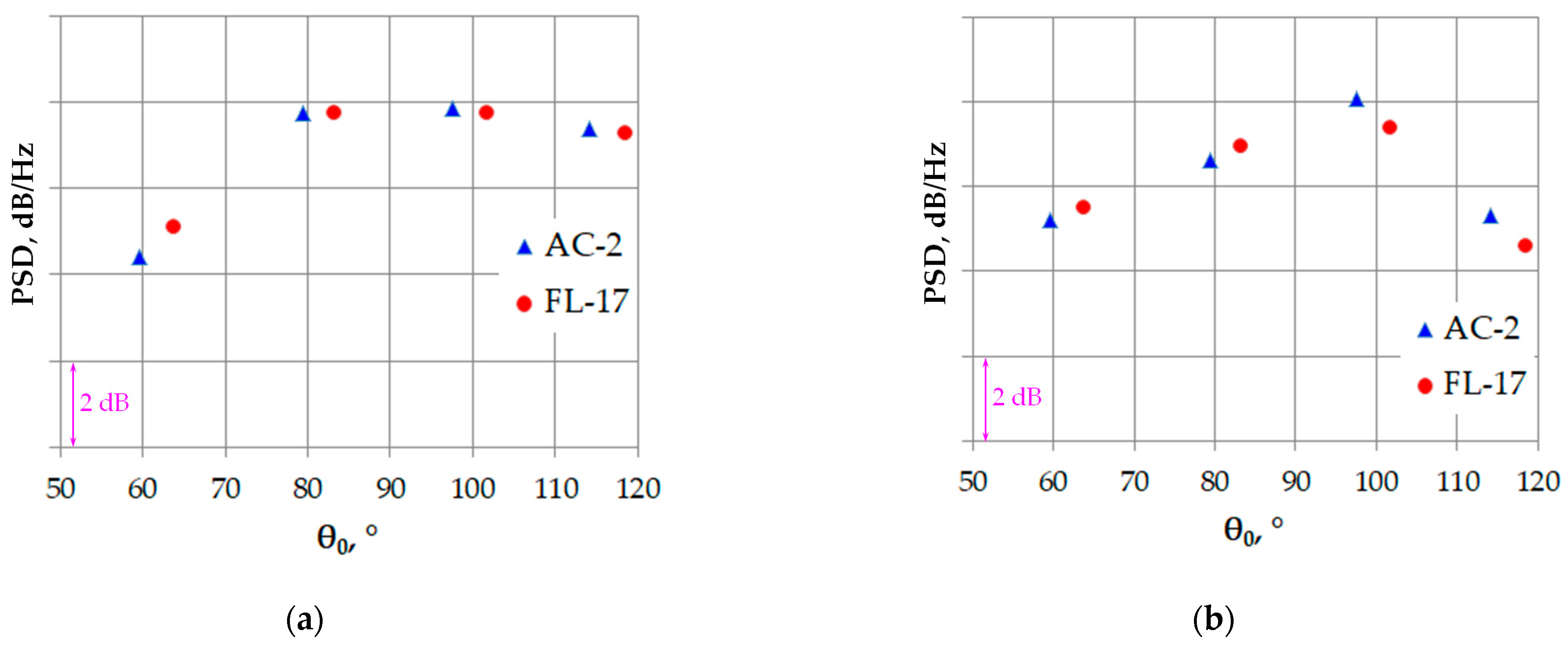
Figure 14 shows the spectra for the same landing gear model and flow speed, but for different azimuthal angles θ. The effect of flow speed is demonstrated in
Figure 15 for the same landing gear model. Again, a good agreement is observed.
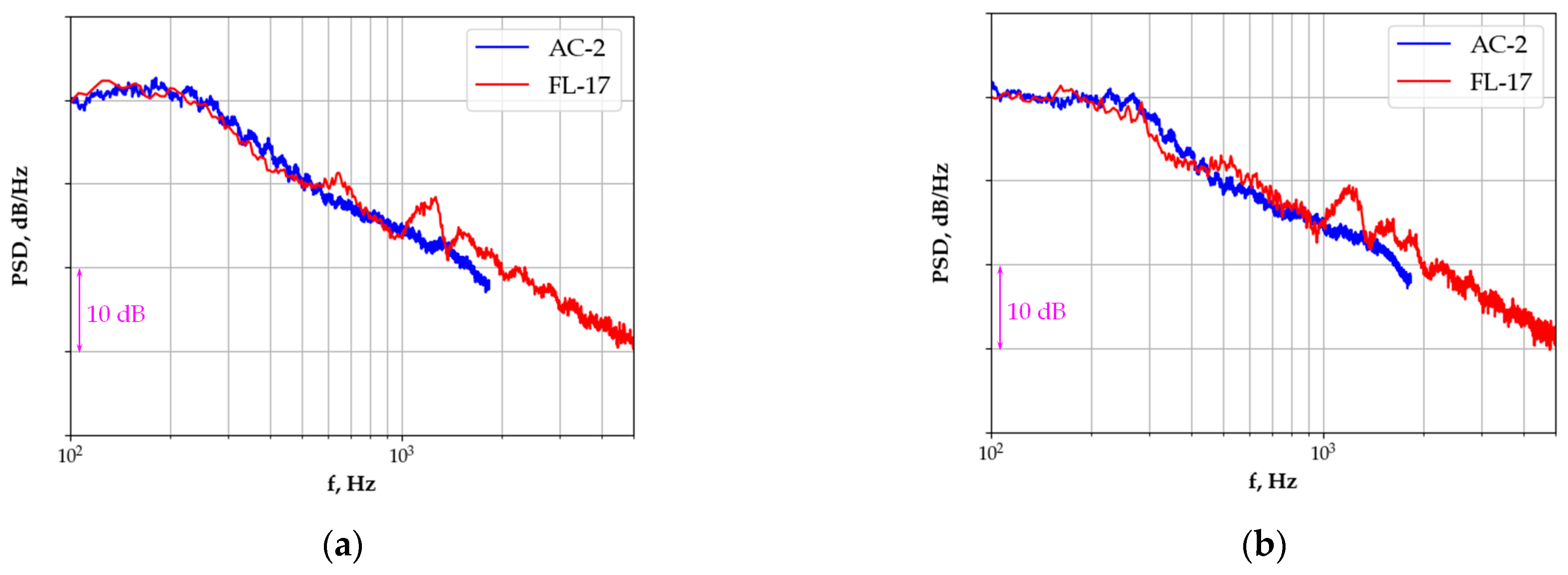
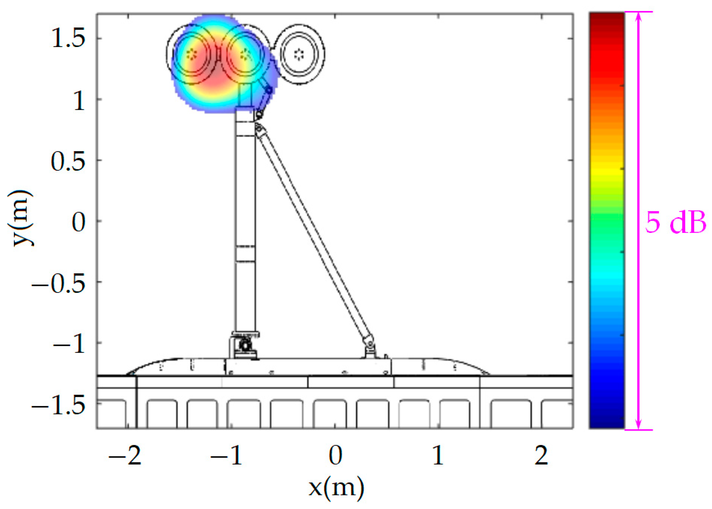
Finally,
Figure 16 illustrates the effect of landing gear model geometry, providing results for the six-wheel model with high and medium main legs. The spectra collapse very well, with the possible exception of a hump, which is present in the FL-17 CARDC spectra at the frequency ~1250 Hz. Localization of the noise sources for the frequency is shown in
Figure 17 and demonstrates that the hump is likely to be related to the support structure between the wheels, so that the noise generation mechanism can be similar to that considered in [
22] for two-wheel landing gear models. Investigation of wheels of different diameters in [
22] leads to a conclusion that the tonal noise can be generated by a laminar flow around the support structure between the wheels and is more likely to appear for wheels with smaller diameters, which is exactly the case for the six-wheel landing gear model (
Figure 8a).
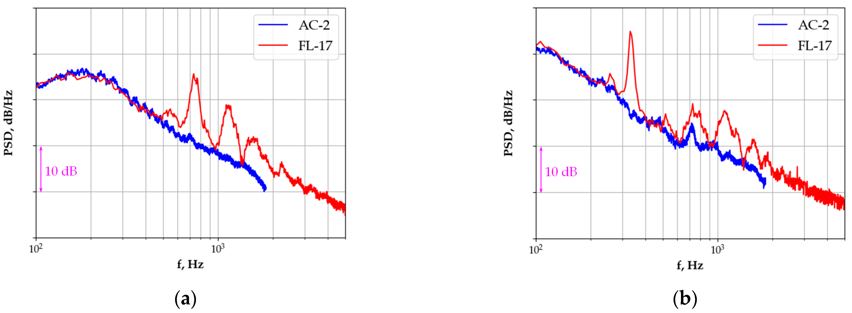
In fact, it seems that while the results of small-scale tests agree reasonably well with the results of large-scale tests in terms of broadband noise of landing gear models, the small-scale tests fail to predict the tonal noise that appeared for some landing gear configurations in FL-17 CARDC. An example of this situation is shown in
Figure 18 for the two-wheel landing gear model.
It can be seen that the normalized spectra from AC-2 TsAGI tests do not exhibit the peaks that are present for FL-17 CARDC data.
The inability of small-scale tests to reproduce tonal noise of the full-scale models is expected. Indeed, the tonal noise is known to strongly depend on the parameters of flow and model geometry [
17]. In particular, the Reynolds number effect plays a prominent role in noise generation for both Aeolian tones and cavity tones. The results of the present study corroborate this conclusion that small-scale tests are ill-suited for tonal noise investigation.
At the same time, a good agreement of noise spectra for broadband noise of the small-scale and large-scale landing gear models implies that the small-scale tests can be used to predict and reduce broadband noise of large-scale landing gear models.
6. Conclusions
We performed acoustic measurements of large-scale and small-scale landing gear models, which have identical simplified geometry and differ only by their scales. The tests of the full-scale generic landing gear were performed in the large anechoic facility FL-17 CARDC (Mianyang, China), whereas the small-scale landing gear models were tested in an anechoic chamber with flow, AC-2 TsAGI (Moscow, Russia).
The large-scale landing gear models are simplified and lack small geometric details, which for the first time allows their results to be directly compared with those for small-scale models of the same geometry. It is shown that the normalized spectra for broadband noise of the landing gear models of different scales are in a good agreement with each other. This conclusion implies that the small-scale tests can be reliably used to search for broadband noise reduction solutions, at least for the low-frequency region of full-scale noise spectra. One can mention the technology of truncated cylinders for landing gear noise reduction [
21], which was initially developed for small-scaled cylinders and landing gear models and then successfully validated for low-frequency noise reduction at the full scale. Such studies can be continued with respect to other low-frequency noise reduction technologies. Small-scale tests can also be used for refinement of semi-empirical models of broadband noise prediction for different landing gear elements.
On the other hand, development of noise reduction technologies for high-frequency parts of the spectrum based on small-scale models seems problematic, because it requires high-fidelity reproduction of fine details of the landing gear, measuring the noise spectra up to very high frequencies, and introduction of large corrections due to sound refraction by the flow and sound attenuation in the atmosphere.
The present study also corroborates the conclusion that small-scale tests are ill-suited for tonal noise investigation for full-scale models due to high sensitivity of the tones to the parameters of flow and model geometry. This is not a significant drawback, however, because the tonal noise of full-scale landing gears should be effectively reduced with a number of noise reduction methods, both for Aeolian tones and cavity tones; thus, realistic landing gears have their tonal noise suppressed, so that their aerodynamic noise is essentially broadband in nature [
2]. This means that investigations of broadband noise of landing gears in small-scale tests can be of practical interest.


