Abstract
Inerter is a novel type of mechanical element. As the important composition of vibration control systems, inerters are widely used. Meanwhile, the operation security issue of the inerter is becoming increasingly prominent. Dynamic-breakdown of the inerter (DBoI) means that the inerter’s two terminals come into contact, which can cause a huge impact force and destroy the system. The ball-screw inerter is an essential protype of inerters. The existence of dynamic-breakdown of a single inerter has been already proved by previous research. To confirm whether DBoI exists in the inerter-spring-damper (ISD) system, the research focuses on the dynamic-breakdown of a ball-screw inerter (DBoBSI) in the ISD system. The dynamic model of the DBoI in the ISD system is established and analyzed. On account of the model and analysis, DBoBSI is analyzed. A novel experimental system is established and experiments of DBoBSI in the ISD system are carried out. The coefficient of restitution et changes slightly with a value of about 0.5. The variation of momentum is nearly equal to the impulse, with an error within 15%. On account of the experimental data collected, the conclusions are that there is a DBoBSI in the ISD system, and the impact force during DBoI in the ISD system ought to be avoided.
1. Introduction
Inerter is a novel type of mechanical element, which was proposed by Smith [1]. The dynamic characteristic of the inerter is inertia. The forces applied on the inerter’s two terminals are proportional to the two terminals’ relative acceleration. Therefore, the proportion’s unit is the same as the mass. The proportion is known as the inertance of inerters. Based on the force-current analogy theory, the inerter-spring-damper (ISD) system corresponds to the capacitor-inductor-resistor system [2]. On account of the theory, the network synthesis method used in electrical systems can be applied to mechanical systems.
On account of the ISD system and the network synthesis method, various mechanical networks have been proposed [3,4]. For example, the inerter-based vibration isolator [5,6,7,8], the tuned mass damper inerter system (TMDI) [9,10,11,12], the tuned inerter damper system (TID) [13,14,15], etc. There are inerters with different categories of physical structures, for instance, the ball-screw based [16,17,18], the rack and pinion based [16,19], the fluid-based [20,21], and electromagnetic-based inerters [22,23,24], etc. The inerter-based vibration control method has been successfully applied in vehicle suspension systems [25,26], aircraft landing gear suspension systems [27,28], building vibration control systems [29,30], etc. The research on modeling, design, analysis, and application of inerter have been persistently focused.
With the wide applications of the inerter, the operation security issue is becoming increasingly important. For example, the dynamic characteristics of the ISD system with impulsive excitations has been researched [31]. Different from the research in [31], the dynamic-breakdown problem of the inerter is an extreme situation. The definition of the dynamic-breakdown of the inerter (DBoI) is that “the inerter’s two terminals come into contact”. If DBoI occurs, the inerter’s two terminals impact reciprocally and the kinetic energy of the inerter is instantly released. DBoI can cause huge impact forces, and destroy the inerter itself and the system. The existence and dynamic characteristics of dynamic-breakdown of a single inerter is studied by [32]. As an essential protype of inerters, the ball-screw inerter is widely used.
Different from [32], to confirm whether DBoI exists in an ISD system, especially when the inerter is connected with a spring in parallel, the research focuses on the dynamic-breakdown of a ball-screw inerter (DBoBSI) in an ISD system. However, the experimental system in [32] is only suitable for the dynamic-breakdown of a single ball-screw inerter. Experiments of DBoBSI in the ISD system cannot be conducted in the experimental system in [32]. Therefore, the novelty of the research is that the ball-screw inerter is connected with a rectangular spring in parallel, and a novel dynamic-breakdown experimental system is established. Experiments of DBoBSI in the ISD system can be conducted in this newly established experimental system. The necessity of the research is to confirm whether DBoI exists in the ISD system, which is quite important for the operation security of the inerter.
Also, the main objective of this research is to confirm whether DBoI exists in the ISD system, and explore its dynamical characteristics. In Section 2, the dynamic model of the DBoI in the ISD system is established and analyzed. On account of the dynamic model and analysis, in Section 3, a novel experimental system is established, and experiments of DBoBSI in the ISD system are conducted. On account of the experimental data, huge impact forces are caused by DBoBSI. The impact forces collected by experiments are much larger than the weight of the ball-screw inerter itself. In Section 4, the conclusions are that there is a DBoBSI in the ISD system, and the impact force during DBoI in the ISD system ought to be avoided.
2. Modeling and Analysis of the DBoI in ISD System
The definition of the DBoI is that “the inerter’s two terminals come into contact”. If DBoI occurs, the inerter’s two terminals impact reciprocally, and the inerter’s kinetic energy is instantly released and causes a huge impact force. If the impact force breaks through the strength limit of the inerter, the inerter will be destroyed and the system can be damaged. Due to the huge impact force caused by the DBoI, the operation security issue of the inerter cannot be ignored. Similar to the DBoI, the definition of DBoI in the ISD system is that “the inerter’s two terminals in ISD system come into contact”. To analyze the impact forces and other dynamic characteristics of the DBoI in the ISD system, a dynamic model is established and analyzed.
2.1. Modeling of the DBoI in the ISD System
A typical ISD system comprises a spring, an inerter, and a damper. In general, an inerter is connected with a protective or tuning spring in parallel. Ignoring the influence of the damper, the dynamic-breakdown issue of an inerter connected with a spring in series can be seen as the issue of DBoI. This research focuses on the DBoI in the ISD system, especially when the inerter is connected with a spring in parallel. The diagram of a typical ISD system is shown in Figure 1.
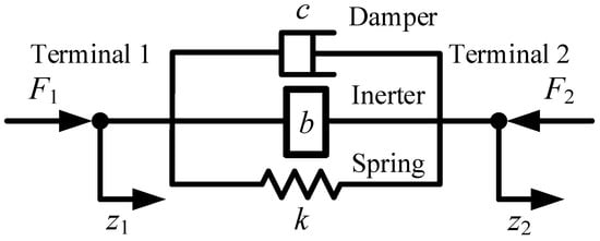
Figure 1.
Diagram of a typical ISD system.
As shown in Figure 1, forces acted on shown two terminals are denoted as F1 and F2. The displacements of the two terminals are denoted as z1 and z2. The inerter’s inertance is denoted as b, the spring’s stiffness is denoted as k, and the damper’s damping coefficient is denoted as c. F1 and F2 can be expressed by Equation (1).
where v1 and v2 are the derivatives of z1 and z2, i.e., the velocities of the two terminals, respectively. a1 and a2 are the second derivatives of z1 and z2, i.e., the accelerations of the two terminals, respectively.
Physical inerters in ISD systems have certain strokes. When the two terminals’ relative displacement of the inerter in the ISD system reaches the limited stroke, DBoI will occur. Inerter’s stroke in the ISD system is denoted as L. Taking one of the two terminals of the inerter as the reference frame, for example, terminal 2, and a dynamic model of the DBoI in a typical ISD system is founded, as shown in Figure 2.
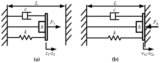
Figure 2.
Dynamic model of the DBoI in a typical ISD system. (a) Before dynamic-breakdown; (b) During dynamic-breakdown.
Figure 2a shows the status before the DBoI in a typical ISD system. Figure 2b shows the status during the DBoI. When DBoI in the ISD system occurs, the inerter’s two terminals begin to contact instantly, the inerter’s kinetic energy is released and results in impulse. The impulse caused by DBoI in the ISD system is denoted as Pt. The impact force is denoted as Fp.
Actually, the DBoI in the ISD system is a short process. The start time of dynamic-breakdown is denoted as tc, when the two terminals begin to contact. The end time of dynamic-breakdown is denoted as tt, when the two terminals disconnect. When DBoI in the ISD system occurs, the dynamic relation can be expressed by Equation (2).
During the dynamic-breakdown, the integral form of Equation (2) can be expressed as Equation (3).
The impulse caused by DBoI in ISD system, Pt can be expressed as Equation (4).
2.2. Response Analysis of the DBoI in ISD System
On account of the dynamic relations, the details of the DBoI in the ISD system are further analyzed. Equation (3) can be solved and further expressed by Equation (5).
During the DBoI in the ISD system, the inerter’s two terminals remain in contact. Therefore, the relative displacement z1-z2 can be seen as a constant. Then, the relative displacement variation during the dynamic-breakdown can be seen as zero. That means the influence of the damper is minor and can be seen as zero. That is why the influence of the damper in the ISD system is ignored at the beginning of Section 2.1. Equation (5) can be further expressed by Equation (6).
where v1t − v2t is the relative velocity of the two terminals, when the two terminals disconnect. v1c − v2c is the relative velocity of the two terminals, when the two terminals begin to contact.
Actually, the duration of the impulse Pt is short. That means the influence of the spring is minor. A dangerous situation is that the inerter causes almost the entire impulse. That means the impact force is much larger than the force k(z1 − z2). This dangerous situation ought to be focused on when designing the inerter and the ISD system. If the influence of the spring is ignored, Equation (6) can be simplified as Equation (7). Therefore, Equation (7) is an approximate equation.
Under the dangerous situation, the huge impact forces caused by the DBoBSI in the ISD system may destroy the inerter and the system. The dangerous situation is mainly discussed below. The dynamic-breakdown issue is simplified based on the dangerous situation, and the approximate Equation (7) is applied.
The left part of Equation (7) means the variation of the inerter’s momentum in the ISD system during DBoI. The absolute value of the variation is denoted as Mc, as expressed by Equation (8).
The coefficient of restitution of the DboI in the ISD system is denoted as et, as expressed by Equation (9).
Synthesize Equations (7) and (9), an approximate equation is obtained and expressed by Equation (10).
Equation (10) can be verified by experiments of DBoBSI in the ISD system in Section 3. On account of the analysis above, the basic method of solving the dynamic-breakdown issue of DBoBSI in the ISD system is obtained.
3. Experiments of DBoBSI in ISD System
On account of the modeling as well as analysis of the DBoI in the ISD system, experiments of DBoBSI in the ISD system are conducted. A novel experimental system is established and analyzed. Then, groups of experiments of DBoBSI in the ISD system are carried out.
3.1. Experimental System of DBoBSI in ISD System
As an essential protype of inerters, the ball-screw inerter is widely used in categories of vibration control systems. The diagram of the ball-screw inerter in [16,17,18] is shown in Figure 3. The ball-screw inerter comprises a housing, a nut, a screw, bearings, a flywheel, as well as other components. One of the ball-screw inerter’s two terminals is the housing, and the other is the screw.
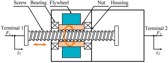
Figure 3.
The mechanical diagram of the ball-screw inerter in [16,17,18].
When the ball-screw inerter’s two terminals are relatively translated, the flywheel and the nut make a coupled rotational motion. The transmission relationship of the ball-screw inerter’s two terminals can be expressed by Equation (11) [32].
where ω12 is the angular velocity of the nut as well as the flywheel. The lead of the ball-screw pair is denoted as p. The ball-screw inerter’s inertance, b, can be expressed by Equation (12) [32].
where Jt is the rotational inertia of coupled rotation components of the ball-screw inerter. Jt is relative to the rotation axes of the coupled rotating components.
On account of the model and analysis of the DBoI in the ISD system, the experimental scheme diagram of DBoBSI is shown in Figure 4. The experimental system in [32] is only suitable for the dynamic-breakdown of a single ball-screw inerter. Experiments of DBoBSI in the ISD system cannot be conducted in the experimental system in [32]. Therefore, in this research, the ball-screw inerter is connected with a rectangular spring in parallel, and a novel dynamic-breakdown experimental system is established. Experiments of DBoBSI in the ISD system can be conducted in this newly established experimental system. Considering the system’s structural damper, the novel experimental system can be seen as a lightly damped ISD system.
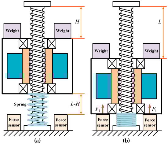
Figure 4.
Diagram of the experiments of DBoBSI in ISD system. (a) Before dynamic-breakdown; (b) During dynamic-breakdown.
One of the ball-screw inerter’s two terminals, the screw, is connected to the reference ground. The other terminal of the ball-screw inerter, the housing, can move downward, influenced by the gravity of the components of the inerter, apart from the screw. The weight blocks are fixed with the housing to increase the weight. The weight of these falling components is denoted as Wt. The mass of the ball-screw inerter itself is denoted as mb. When the housing moves downward, the gravity potential energy of the falling components is mainly converted into the ball-screw inerter’s kinetic energy and the spring’s elastic potential energy. The ball-screw inerter’s stroke, L, contains two parts, H and L-H, as shown in Figure 4. During dynamic-breakdown experiments, different L-H are installed to acquire groups of relative impact velocities, v1c − v2c.
And then, the two terminals’ relative displacement of the ball-screw inerter in the ISD system reaches the limited stroke, and DBoBSI in the ISD system occurs. When DBoBSI in the ISD system occurs, the two terminals impact reciprocally, the ball-screw inerter’s kinetic energy is instantly released, and huge impact forces are caused.
On account of the experimental scheme, a novel experimental system of the DBoBSI in the ISD system is established, as shown in Figure 5.
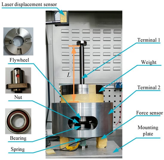
Figure 5.
The novel experimental system of the DBoBSI in ISD system.
The novel dynamic-breakdown experimental system of the DBoBSI in the ISD system comprises a spring, a ball-screw inerter, two force sensors, a mounting plate, a laser displacement sensor, and other adapting pieces. The ball-screw inerter is connected with a rectangular spring in parallel. Experiments of DBoBSI in the ISD system can be conducted in this newly established experimental system.
One of the ball-screw inerter’s two terminals, the screw, is connected to the mounting plate. The mounting plate is immovable. The other terminal of the ball-screw inerter, the housing, can move downward, influenced by the gravity of the components of the inerter, apart from the screw. The five pieces of weight blocks are fixed with the housing to increase the weight. The key components of the novel experimental dynamic-breakdown system and the stroke of the ball-screw inerter L are marked in Figure 5. Once L-H is installed, the housing can move downward. Finally, the housing contacts with the probe of the force sensors, which means DBoBSI in the ISD system occurs. During dynamic-breakdown, the two terminals impact reciprocally, and the ball-screw inerter’s kinetic energy is instantly released and causes a huge impact force.
The parameters in the experiment system of the DBoBSI in ISD system are shown as Table 1.

Table 1.
The parameters in the experiment system of the DBoBSI in ISD system.
During dynamic-breakdown experiments, the relative displacements, z1 − z2, are measured by the displacement sensor. On account of the data of displacements, relative velocities, v1 − v2, can be calculated. The impact forces can be measured by the force sensors. Impact forces measured by one of the two force sensors, are denoted as Ft. The force sensors used are of the same type, and the impact forces measured by them are almost equal. Due to the limitation of the test conditions, the impact forces of only one of the two force sensors can be obtained during one dynamic-breakdown experiment.
The impulse of the DBoBSI in the ISD system here, Pt can be expressed by Equation (13).
Considering the influence of the weight Wt, Equation (6) can be modified as Equation (14). However, the impulse Pt is short, and also considering the dangerous situation that the impact forces are much larger than the force k(z1 − z2) as well as weight Wt, the simplified Equation (8) is used to calculate the variation of the ball-screw inerter’s momentum in ISD system, Mc, during dynamic-breakdown. In other words, the influence of the spring and the weight is ignored here.
3.2. Dynamic-Breakdown Experiments and the Results
On account of the experimental system of the DBoBSI in the ISD system, dynamic-breakdown experiments are conducted, and the results are analyzed.
The relative displacements as well as velocities during the processes of the DBoBSI in the ISD system are shown in Figure 6. L-H are installed as 204.5 mm, 202.1 mm, 196.2 mm, 189.3 mm, and 185.7 mm, respectively.
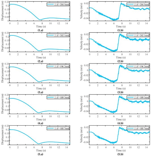
Figure 6.
The relative displacements as well as velocities during the processes of the DBoBSI in ISD system. (1.a–5.a) Displacements; (1.b–5.b) Velocities.
For example, Figure 6(1.a) shows the relative displacements during dynamic-breakdown, measured by the laser displacement sensor. Figure 6(1.b) shows the relative velocities, which are valid and calculated by the displacements. When L-H is installed as 204.5 mm, the housing moves downward, the relative displacement z1 − z2 decreases and the falling components’ gravity potential energy is mainly converted into the ball-screw inerter’s kinetic energy and the spring’s elastic potential energy.
Then, the relative displacement reaches the limited stroke and dynamic-breakdown occurs. When DBoBSI in the ISD system occurs, the housing and the two force sensors impact each other. The two terminals’ relative velocity increases dramatically and suddenly. Meanwhile, the inerter’s kinetic energy is instantly released and causes a huge impact force. Then the two terminals disconnect and may rebound several times.
Figure 6(2.a) shows the relative displacements during dynamic-breakdown, and Figure 6(2.b) shows the relative velocities which are calculated by the displacements, when L-H is installed as 202.1 mm. Figure 6(3.a) shows the relative displacements during dynamic-breakdown, and Figure 6(3.b) shows the relative velocities which are calculated by the displacements, when L-H is installed as 196.2 mm. Figure 6(4.a) shows the relative displacements during dynamic-breakdown, and Figure 6(4.b) shows the relative velocities which are calculated by the displacements, when L-H is installed as 189.3 mm. Figure 6(5.a) shows the relative displacements during dynamic-breakdown, and Figure 6(5.b) shows the relative velocities which are calculated by the displacements, when L-H is installed as 185.7 mm. Results here, are similar in these dynamic-breakdown experiments of the DBoBSI in the ISD system.
The impact forces, which are measured by one of the two force sensors during dynamic-breakdown, are shown in Figure 7, when L-H are installed as 204.5 mm, 202.1 mm, and 196.2 mm. Figure 7 shows that the peak impact forces of one of the two force sensors are more than 3000 N. That means that the peak impact forces of the two force sensors are more than 6000 N. The impact forces collected are much larger than the force k(z1 − z2) and the weight Wt. The maximum value of the supporting force of the spring connected in parallel with the ball-screw inerter is no more than 400 N. The weight Wt is 166 N. Therefore, the dynamic-breakdown experiments here, are suitable for the dangerous situation that the inerter causes almost the entire impulse. The huge impact forces may destroy the ball-screw inerter as well as the system. The dangerous situation should be mainly concerned and researched, when designing inerters as well as the system. It can be verified that there is a DBoBSI in the ISD system, and the impact force during DBoI in the ISD system ought to be avoided.
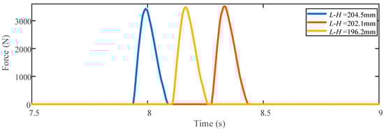
Figure 7.
Impact forces when dynamic-breakdowns occur.
Results of the experiments of the DBoBSI in the ISD system are shown in Table 2. When DBoBSI in the ISD system occurs, the coefficient of restitution et changes slightly, and the variation of momentum Mc is nearly equal to the impulse Pt. The error is within 15%. The error bars of the impulse Pt and its theoretical value Mc are shown in Figure 8. There is energy loss during the process of mutual transformation between the momentum and the impulse. Actually, the experimental results and the errors are credible, because of the assumption of the dangerous situation, the test error, the random factor, the energy loss, as well as the limitation of the experimental conditions. Equation (10) can be verified by the dynamic-breakdown experiments here. The variation of momentum Mc and the impulse Pt can be approximately equal to each other, in the simplified calculation of engineering.
Table 2.
Results of the experiments of the DBoBSI in ISD system.
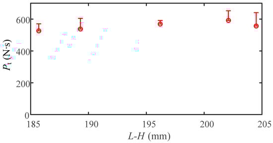
Figure 8.
The error bars of the impulse Pt and its theoretical value Mc.
But if the test conditions are better enough, the error can be further researched in the future, and Equation (14) can be further verified.
On account of the experiments of the DBoBSI in the ISD system, there ought to be a maximum value of allowable relative impact velocity, which is denoted as [v1c − v2c]. If the relative impact velocity is significantly larger than [v1c − v2c], the ball-screw inerter in the ISD system will be destroyed. [v1c − v2c] can be calculated by approximate Equation (15).
where [Pt] is the maximum value of allowable impulse during DBoBSI in the ISD system.
During the process of designing a ball-screw inerter in the ISD system, [Pt] can be obtained by impact experiments and experience rules as well as impact theory. The coefficient of restitution et can be set in an adequate range by experimental experiences. For example, if one ISD system is just like the experimental system here, et can be set as 0.5, to calculate an approximate value of [v1c − v2c]. et can set slightly larger than experimental results and experiences, for safety. After the ball-screw inerter’s inertance in the ISD system is preliminarily determined, the maximum value of allowable relative impact velocity [v1c − v2c] can be obtained. There will be a balance of the objective value of inertance and the maximum value of allowable relative impact velocity [v1c − v2c], when eventually determining the ball-screw inerter’s inertance in the ISD system.
However, please note that Equation (15) is an approximate formula and suitable for the dangerous situation that the inerter almost causes the entire impulse. Under the dangerous situation, the huge impact forces caused by the DBoBSI in the ISD system may destroy the ball-screw inerter and the system. Therefore, the dangerous situation should be mainly concerned and researched, when designing inerters as well as the system.
4. Conclusions
This research focuses on the issue of DBoBSI in the ISD system. The objective of this research is to confirm whether DBoI exists in the ISD system, and explore the dynamical characteristics of the ball-screw inerter in the ISD system. A dynamical model of the DBoI in the ISD system is established and analyzed. On account of the model and analysis, a novel experimental system is built. Then, experiments of DBoBSI in the ISD system are conducted and analyzed. On account of the experimental results, a huge impact force is caused by the DBoBSI in the ISD system. The impact forces are much larger than the weight of the ball-screw inerter itself.
The summative conclusions are that there is a DBoBSI in the ISD system, a novel dynamic-breakdown experimental system is established and the impact force and the maximum value of allowable relative impact velocity during DBoI in the ISD system ought to be considered. The main conclusions can be stated as below:
1. DBoI exists in the ISD system. Even if the inerter is connected with a protective spring in parallel, the DBoBSI in the ISD system can occur. When DBoBSI in the ISD system occurs, the dangerous situation that the inerter almost causes the entire impulse should be avoided, because of the huge impact force.
2. In this research, the ball-screw inerter is connected with a rectangular spring in parallel, and a novel dynamic-breakdown experimental system is established. The experimental system in [32] is only suitable for the dynamic-breakdown of a single ball-screw inerter. Experiments of DBoBSI in the ISD system cannot be conducted in the experimental system in [32]. Experiments of DBoBSI in the ISD system can be successfully conducted in the novel established experimental system.
3. On account of the experiments of the DBoBSI in the ISD system, there ought to be a maximum value of allowable relative impact velocity. Under the dangerous situation that the inerter almost causes the entire impulse, the maximum value of allowable relative impact velocity [v1c − v2c] can be calculated by approximate Equation (15). The coefficient of restitution et changes slightly with a value of about 0.5. The variation of momentum Mc is nearly equal to the impulse Pt. The error is within 15%. This result is consistent with [32].
The research focuses on the dangerous situation that the inerter almost causes the entire impulse. Based on the dangerous situation, the dynamic-breakdown issue of the DBoBSI in the ISD system is simplified. The dangerous situation should be mainly concerned and researched. The research can improve the operation security of the inerter. However, the limitation of the research is that only the dangerous situation is researched. Dynamic-breakdown issues of other kinds of situations and other categories of inerters will be further researched in future works. The research and the novel experimental system will be the benefit for the research of dynamic-breakdown and design of the ISD system.
Author Contributions
Conceptualization, Y.L. and N.H.; methodology, N.H. and Z.C.; software, Y.L. and Z.Y.; validation, Y.Y., L.Z., L.H. and Z.Y.; formal analysis, Y.Y. and L.Z.; investigation, N.H.; resources, N.H.; data curation, Z.Y.; writing—original draft preparation, Y.L.; writing—review and editing, Z.C.; visualization, L.H.; supervision, N.H.; project administration, N.H.; funding acquisition, Z.C. All authors have read and agreed to the published version of the manuscript.
Funding
This research was funded by the National Natural Science Foundation of China (grant number 52275140, 51975576).
Institutional Review Board Statement
Not applicable.
Informed Consent Statement
Not applicable.
Data Availability Statement
Not applicable.
Conflicts of Interest
The authors declare no conflict of interest.
References
- Smith, M.C. Synthesis of mechanical networks: The inerter. IEEE Trans. Automat. Control 2002, 47, 1648–1662. [Google Scholar] [CrossRef]
- Smith, M.C. The inerter: A retrospective. Annu. Rev. Control Robot. Auton. Syst. 2020, 3, 361–391. [Google Scholar] [CrossRef]
- Chatterjee, S. On the principle of impulse damper: A concept derived from impact damper. J. Sound Vib. 2008, 312, 584–605. [Google Scholar] [CrossRef]
- Al-Obaidi, A.R.; Mohammed, A.A. Numerical Investigations of Transient Flow Characteristic in Axial Flow Pump and Pressure Fluctuation Analysis Based on the CFD Technique. J. Eng. Sci. Technol. Rev. 2019, 12, 70–79. [Google Scholar] [CrossRef]
- Liu, C.; Chen, L.; Lee, H.P.; Yang, Y.; Zhang, X. A review of the inerter and inerter-based vibration isolation: Theory, devices, and applications. J. Frankl. Inst. 2022, 359, 7677–7707. [Google Scholar] [CrossRef]
- Kuhnert, W.M.; Gonçalves, P.J.P.; Ledezma-Ramirez, D.F.; Brennan, M.J. Inerter-like devices used for vibration isolation: A historical perspective. J. Frankl. Inst. 2021, 358, 1070–1086. [Google Scholar] [CrossRef]
- Yang, J.; Jiang, J.Z.; Neild, S.A. Dynamic analysis and performance evaluation of nonlinear inerter-based vibration isolators. Nonlinear Dyn. 2019, 99, 1823–1839. [Google Scholar] [CrossRef]
- Moraes, F.d.H.; Silveira, M.; Gonçalves, P.J.P. On the dynamics of a vibration isolator with geometrically nonlinear inerter. Nonlinear Dyn. 2018, 93, 1325–1340. [Google Scholar] [CrossRef]
- Zhang, Z.; Fitzgerald, B. Tuned mass-damper-inerter (TMDI) for suppressing edgewise vibrations of wind turbine blades. Eng. Struct. 2020, 221, 110928. [Google Scholar] [CrossRef]
- Ruiz, R.; Taflanidis, A.A.; Giaralis, A.; Lopez-Garcia, D. Risk-informed optimization of the tuned mass-damper-inerter (TMDI) for the seismic protection of multi-storey building structures. Eng. Struct. 2018, 177, 836–850. [Google Scholar] [CrossRef]
- Pietrosanti, D.; De Angelis, M.; Giaralis, A. Experimental study and numerical modeling of nonlinear dynamic response of SDOF system equipped with tuned mass damper inerter (TMDI) tested on shaking table under harmonic excitation. Int. J. Mech. Sci. 2020, 184, 105762. [Google Scholar] [CrossRef]
- Javidialesaadi, A.; Wierschem, N.E. Design and performance evaluation of inerter-based tuned mass dampers for a ground acceleration excited structure. Soil. Dyn. Earthq. Eng. 2021, 140, 106463. [Google Scholar] [CrossRef]
- Siami, A.; Cigada, A.; Karimi, H.; Zappa, E. Vibration Protection of a Famous Statue against Ambient and Earthquake Excitation Using A Tuned Inerter–Damper. Machines 2017, 5, 33. [Google Scholar] [CrossRef]
- De Domenico, D.; Impollonia, N.; Ricciardi, G. Soil-dependent optimum design of a new passive vibration control system combining seismic base isolation with tuned inerter damper. Soil. Dyn. Earthq. Eng. 2018, 105, 37–53. [Google Scholar] [CrossRef]
- Shen, W.; Niyitangamahoro, A.; Feng, Z.; Zhu, H. Tuned inerter dampers for civil structures subjected to earthquake ground motions: Optimum design and seismic performance. Eng. Struct. 2019, 198, 109470. [Google Scholar] [CrossRef]
- Chen, M.; Papageorgiou, C.; Scheibe, F.; Wang, F.-C.; Smith, M. The missing mechanical circuit element. IEEE Circuits Syst. Mag. 2009, 9, 10–26. [Google Scholar] [CrossRef]
- Shen, Y.; Chen, L.; Yang, X.; Shi, D.; Yang, J. Improved design of dynamic vibration absorber by using the inerter and its application in vehicle suspension. J. Sound Vib. 2016, 361, 148–158. [Google Scholar] [CrossRef]
- Li, Y.; Cheng, Z.; Hu, N.; Yang, Y.; Xiao, Z. Modeling, design and experiments of a ball-screw inerter with mechanical diodes. J. Sound Vib. 2021, 504, 116121. [Google Scholar] [CrossRef]
- Petrini, F.; Giaralis, A.; Wang, Z. Optimal tuned mass-damper-inerter (TMDI) design in wind-excited tall buildings for occupants’ comfort serviceability performance and energy harvesting. Eng. Struct. 2020, 204, 109904. [Google Scholar] [CrossRef]
- Liu, X.; Titurus, B.; Jiang, J.Z. Generalisable model development for fluid-inerter integrated damping devices. Mech. Mach. Theory 2019, 137, 1–22. [Google Scholar] [CrossRef]
- Shen, Y.; Chen, L.; Liu, Y.; Zhang, X. Influence of fluid inerter nonlinearities on vehicle suspension performance. Adv. Mech. Eng. 2017, 9, 1687814017737257. [Google Scholar] [CrossRef]
- Shen, W.; Long, Z.; Cai, L.; Niyitangamahoro, A.; Zhu, H.; Li, Y.; Qiu, C. An inerter-based electromagnetic damper for civil structures: Modeling, testing, and seismic performance. Mech. Syst. Sig. Process. 2022, 173, 109070. [Google Scholar] [CrossRef]
- Li, Y.; Shen, W.; Zhu, H. Vibration mitigation of stay cables using electromagnetic inertial mass dampers: Full-scale experiment and analysis. Eng. Struct. 2019, 200, 109693. [Google Scholar] [CrossRef]
- Ning, D.; Sun, S.; Du, H.; Li, W.; Zhang, N.; Zheng, M.; Luo, L. An electromagnetic variable inertance device for seat suspension vibration control. Mech. Syst. Sig. Process. 2019, 133, 106259. [Google Scholar] [CrossRef]
- Shen, Y.; Liu, Y.; Chen, L.; Yang, X. Optimal design and experimental research of vehicle suspension based on a hydraulic electric inerter. Mechatronics 2019, 61, 12–19. [Google Scholar] [CrossRef]
- Hu, Y.; Chen, M.Z.Q.; Sun, Y. Comfort-oriented vehicle suspension design with skyhook inerter configuration. J. Sound Vib. 2017, 405, 34–47. [Google Scholar] [CrossRef]
- Li, Y.; Howcroft, C.; Neild, S.A.; Jiang, J.Z. Using continuation analysis to identify shimmy-suppression devices for an aircraft main landing gear. J. Sound Vib. 2017, 408, 234–251. [Google Scholar] [CrossRef]
- Li, Y.; Jiang, J.Z.; Neild, S.A.; Wang, H. Optimal Inerter-Based Shock–Strut Configurations for Landing-Gear Touchdown Performance. J. Aircraft 2017, 54, 1901–1909. [Google Scholar] [CrossRef]
- Wang, F.C.; Hong, M.F.; Chen, C.W. Building suspensions with inerters. Proc. Inst. Mech. Eng. Part C J. Mech. Eng. Sci. 2009, 224, 1605–1616. [Google Scholar] [CrossRef]
- Giaralis, A.; Petrini, F. Wind-Induced Vibration Mitigation in Tall Buildings Using the Tuned Mass-Damper-Inerter. J. Struct. Eng. 2017, 143, 04017127. [Google Scholar] [CrossRef]
- Zhao, Z.; Hu, X.; Zhang, R.; Chen, Q. Analytical optimization of the tuned viscous mass damper under impulsive excitations. Int. J. Mech. Sci. 2022, 228, 107472. [Google Scholar] [CrossRef]
- Li, Y.; Cheng, Z.; Hu, N.; Yang, Y.; Yin, Z. Study of dynamic breakdown of inerter and the improved design. Mech. Syst. Sig. Process. 2022, 167, 108520. [Google Scholar] [CrossRef]
Disclaimer/Publisher’s Note: The statements, opinions and data contained in all publications are solely those of the individual author(s) and contributor(s) and not of MDPI and/or the editor(s). MDPI and/or the editor(s) disclaim responsibility for any injury to people or property resulting from any ideas, methods, instructions or products referred to in the content. |
© 2023 by the authors. Licensee MDPI, Basel, Switzerland. This article is an open access article distributed under the terms and conditions of the Creative Commons Attribution (CC BY) license (https://creativecommons.org/licenses/by/4.0/).