Article

Improved Surrounding Rock Classification Method for the Middle Rock Pillar of a Small Clear-Distance Tunnel

1
College of Civil Engineering, Tongji University, Shanghai 200092, China
2
Key Laboratory of Geotechnical and Underground Engineering of Ministry of Education, Tongji University, Shanghai 200092, China
3
Xiamen Road and Bridge Construction Group Company Ltd., Xiamen 361026, China
*
Authors to whom correspondence should be addressed.
Appl. Sci. 2023, 13(4), 2130; https://doi.org/10.3390/app13042130
Submission received: 14 January 2023 / Revised: 30 January 2023 / Accepted: 4 February 2023 / Published: 7 February 2023
(This article belongs to the Special Issue Predictive Modeling in Mining and Geotechnical Engineering)

Abstract

:
In tunnel design and construction, proper and accurate classification of rock surrounding tunnels is needed to ensure tunnel construction safety, guarantee construction quality, and reduce project costs. With rapid urbanization, numerous small clear-distance tunnels have been constructed in dense urban road networks. Compared with ordinarily separated tunnels, the construction scale and difficulty of small clear-distance tunnels are greater, and the requirements for the classification of rock surrounding tunnels are accordingly higher. A small clear-distance tunnel in an urban super large and complex underground interchange hub of the Xiamen Haicang Evacuation Channel was selected as the background, and the classification method of the middle rock pillar in a small clear-distance tunnel is presented based on the general classification standard of surrounding rocks. Based on the geometric, physical, and mechanical factors of the middle rock pillar, six indices affecting the stability and quality of the middle rock pillar were selected, and the classification index system of the middle rock pillar was established from the two dimensions of the basic and auxiliary indices. The basic and auxiliary indices were scored using the scoring method, and the different grades of the middle rock pillar were divided according to different scores. The middle rock pillar classification standard was applied to the quality assessment of the middle rock pillar, which provided a basis for the on-site assessment of the quality of the middle rock pillar and proved the accuracy and superiority of the improved classification standard. The newly established classification standard can provide a reference for selecting the correct construction method and supporting structure type for small clear-distance tunnels.

1. Introduction

With the development of traffic engineering, an increasing number of tunnels are being constructed in areas with poor geological conditions [1,2]. Classification of surrounding rock is the basic work of tunnel engineering, and an accurate surrounding rock classification can provide a reliable basis for tunnel design and construction. Tunnel surrounding rock refers to the rock mass within the range of stress redistribution generated around the tunnel excavation or the rock mass affecting its stability after tunnel excavation [3]. The concept of surrounding rock classification was first proposed by Roman, a European scholar, in the 1870s, when he systematically classified limestone. In essence, the surrounding rock classification is used to grade and evaluate the stability of the surrounding rock within the influence range of tunnel excavation. By the end of the 18th century, Wilner qualitatively divided rocks into five categories: crumbly rock, soft rock, fractured rock, subhard rock, and hard rock [4], making the concept of surrounding rock classification gradually known to the engineering community. The surrounding rock classification method has been considered by scholars, who have proposed hundreds of classification methods. In the early 20th century, Platt grading appeared, and in 1946, the Terzagi classification appeared [5]. The surrounding rock classification method considers the factors of the support design and ground stress. Since the 1950s, there has been a classification method for evaluating the stability of engineering rock masses and their corresponding support forms. In 1969, a classification method based on the rock quality index (RQD) was developed. In 1973, Bieniaski established a geomechanical rock mass rating (RMR) classification method based on jointed rock masses [6]. In 1974, Barton classified rocks using the rock quality coefficient Q [7,8]. The mine rock mass classification (MRMR) system was introduced in 1975 [9] and has been modified and expanded many times [10,11]. It has been widely used in coal mining, especially in Australia.
The application research of engineering rock classification was developed in the 1960s in China [12]. From 1954 to 1972, the Platt classification standard with the rock hardness coefficient as the index was mainly used. This classification method had a single index and great limitations, but it was economical and reasonable and was widely used at that time. After 1972, based on a large number of underground constructions and a rich understanding and experience of underground engineering rock mass, it became a multi-index, multi-type, and substantial classification method. With the application of acoustic technology in Japan’s national railway, in 1981, the acoustic surrounding rock classification method for underground caverns was proposed [12]. Since the 1980s, a large number of classification methods have emerged. In 1984, the dynamic classification method of surrounding rock stability was proposed. In 1985, the 89,003 unit of the Chinese People’s Liberation Army proposed the classification of tunnel engineering surrounding rock and its application in the covering design. In 1985, the Southwest Research Institute of the Scientific Research Institute of the Ministry of Railways proposed rock mass classification of railway tunnel engineering. In 1988, the geological study of large underground caverns of hydropower stations and the classification of surrounding rock were proposed. However, there was no unified rock classification standard. From 1989 to 1991 [13], the Standard for Engineering Classification of Rock Masses (GB 50218–94) was compiled [14], which stipulated that the classification of surrounding rock should be based on the BQ index of rock hardness and rock mass integrity. The index was modified by considering the groundwater state, main structural plane occurrence, and initial ground stress. In the Code for Design on Tunnel of Railway (TB 10003–99) [15], promulgated in 1999, referring to the Standard for Engineering Classification of Rock Masses, the elastic wave velocity of surrounding rock was introduced, and the grades of tunnel surrounding rock were divided into I, II, III, IV, V, and VI, from good to bad. From 2004 to 2009, the principles and methods of the standard for engineering classification of rock masses were adopted in the revision of the Code for Design of Road Tunnel [16,17], absorbed the content of the Code for Design on Tunnel of Railway (TB 10003–99), and classified the surrounding rock of highway tunnels. After 10 years of experience, the Standard for Engineering Classification of Rock Mass (GB/T50218–2014) was issued on 27 August 2014, which was a nationwide basic standard and applicable to all kinds of rock engineering [18].
With the application of computers and mathematical methods, many aspects of classification methods for surrounding rocks have been developed. The most widely used classification methods are based on fuzzy mathematics, artificial neural networks, support vector machines (SVMs), and deep learning theory. Based on the concept of relative integrity of the surrounding rock, Peng et al. [19] proposed a calculation method for the relative integrity index of the surrounding rock and established a fuzzy comprehensive evaluation method for rock mass classification by analyzing the influence of tunnel span expansion on the stability of the surrounding rock. Duan et al. [20] introduced a BP neural network method, developed a fast classification parameter standard, graded the excavated tunnel working face according to the classification specification of the tunnel surrounding rock, measured its fast classification parameters, and established a training set of the back propagation (BP) neural network based on the surrounding rock classification results and its corresponding fast classification parameters to obtain the surrounding rock classification model. Liang et al. [21] selected four indices, namely, uniaxial compressive strength, integrity coefficient, cohesion, and softening coefficient, for the soft tunnel surrounding rock to build a classification system of soft tunnel surrounding rock based on normal cloud theory. Yang et al. [22] proposed an intelligent classification method for surrounding rocks based on a one-dimensional convolutional neural network. Ma et al. [23] collected 286 case databases of 10 tunnels, involving nine parameters: rock hardness, weathering degree, rock integrity, rock structure, structural plane integrity, ground stress, groundwater, basic rock quality, and the surrounding rock level. The Bayesian network structure was constructed using the collected database, and quantitative verification was performed using strength analysis. Xue et al. [24] established a new tunnel surrounding rock classification model composed of five key factors: uniaxial compressive strength, rock integrity coefficient, softening coefficient, joint surface coefficient, and groundwater, using principal component analysis and the ideal point method. Pan et al. [25] proposed a dynamic nonlinear surrounding rock deformation prediction algorithm model based on the firefly algorithm and nonlinear autoregressive linear network method, focusing on the dynamic, nonlinear, and highly complex deformation characteristics of the tunnel surrounding rock. Jiang et al. [26] discussed the instability and deformation mechanism of tunnel surrounding rock based on a support vector machine, fuzzy reasoning, Q classification, and other theoretical knowledge combined with the characteristics of the tunnel surrounding rock in China. On this basis, a tunnel surrounding rock classification model based on a support vector machine and fuzzy inference was constructed. Niu et al. [27] selected eight qualitative indicators, namely, rock layer thickness, rock mass structure, degree of chimerism, weathering degree, groundwater characteristics, degree of joint development, hammer tapping sound, and ground stress, as evaluation factors, using actual data collected from the tunnel as samples to train the support vector machines of different kernel functions; the authors obtained the mapping relationship between the evaluation factors and the surrounding rock level, so that unknown surrounding rock samples could be classified. Liu et al. [28] combined deep learning technology and an intelligent interpretation method for rock fissure images to calculate the number and spacing of surrounding rock joint groups to describe the degree of structural plane integrity, and then used the color model to determine the rock types to describe the hardness of rock. Finally, the discriminant factors of the surrounding rock classification were converted into BQ values for classification, and the final results of the surrounding rock classification were obtained.
The overall classification trend was obtained by considering only a single factor to juxtapose a few factors and then juxtaposing multiple factors. Presently, the general development trend is based on the stability of the tunnel surrounding rock, considering the effect of various factors on the stability of the surrounding rock and the evaluation method of the comprehensive analysis of multiple factors. In general, the current surrounding rock classification, which has been widely used, generally adopts the method of combining qualitative description and quantitative evaluation, and uses the composite index obtained by simple calculation between multiple factors to characterize the characteristics of rock masses,. Ideas from other disciplines are used to expand the classification method. The current surrounding rock classification system has established more general and unified classification standards, such as the RQD, Q, and RMR methods. Due to the vast territory of China, different rock mass environments between regions, different structural forms and section sizes, different levels of importance of projects, different construction methods and tunnel forms, etc., the surrounding rock classification should also consider the pertinence and specialization of the classification.
In recent years, small clear-distance tunnels have been widely used in urban and highway tunnels due to their unique advantages, such as low environmental damage, small area, beautiful appearance, and convenient route planning [29,30,31]. Because the middle rock pillar of the small clear-distance tunnel is relatively thin, it is significantly affected by the mutual excavation of the two tunnels. The surrounding rock classification method for highway tunnels has considered many important factors affecting the stability of the surrounding rock of highway tunnels, with strong adaptability. However, the current classification result cannot satisfy the requirements for protecting the middle rock pillar of a small clear-distance tunnel in design and construction. The method for reasonably judging the state of the middle rock pillar is of great significance to ensure the safety of small clear-distance tunnels during the design, construction, and operation periods. In this study, the Xiamen Haicang Evacuation Channel Project was selected as the research object, and a new surrounding rock mass classification method for middle rock pillars was developed and proposed. These results can provide a reference for similar engineering applications.

2. Middle Rock Pillar Classification Index Analysis

2.1. Factors Influencing the Stability of the Middle Rock Pillar

The geological environment of highway tunnels includes landforms, formation lithology, geological structures, groundwater conditions, and original geostress states. The RMR classification method considers rock mass characteristics such as rock strength, rock quality, structural plane spacing, discontinuous structural plane characteristics, and groundwater [6]. The Q system of rock mass quality classification mainly considers the influences of rock mass integrity, joint characteristics, groundwater, and ground stress [7]. Referring to the existing surrounding rock classification methods and engineering experience, the quality and stability of the middle rock pillar in a small clear-distance tunnel were mainly controlled by the intrinsic characteristics of the middle rock pillar, such as lithology, rock mass structure type, ground stress state, and groundwater. In addition, external human factors played an important role.

2.1.1. Characteristics of Middle Rock Pillar

The essential characteristics of the middle rock pillar include its physical and mechanical characteristics, structural state, water-bearing state, initial stress state, and degree of weathering.
The physical and mechanical properties of the middle rock pillar reflect the weight, compressive strength, shear strength, compression modulus, water content, cohesion, and internal friction angle of the rock mass. Rock masses with high gravity and strength have good quality and stability.
The structural state of the middle rock pillar refers to the primary structure and secondary variation characteristics of the rock mass. The structural state is refined into the development degree, undulation and extension properties, filling and cementation conditions, and number and density of structural planes, which can reflect the integrity and compactness of the rock mass itself.
The water content in the middle rock pillar will affect the softening, strength reduction, and even instability of the rock mass. For the middle rock pillar, when there is a weak structural plane or interlayer, water reduces the friction resistance of the structural plane and induces the rock mass to slide along the weak plane. Meanwhile, the dissolution of water in the soluble rock and clay rock obviously affects the quality of the rock mass.
The stress release and redistribution caused by the excavation of the tunnels on both sides of the small clear-distance tunnel directly affect the secondary stress state of the middle rock pillar. When the initial stress is not high and the middle rock pillar is strong enough to withstand the secondary stress after tunnel excavation, the initial stress has no significant impact on the stability of the rock mass. When the initial stress is sufficiently high to prevent the rock mass from withstanding the secondary stress, the excavation of the tunnels on both sides will be affected and the middle rock pillar will be unstable and destroyed.
The weathering degree of the middle rock pillar affects the physical and mechanical properties of the rock mass, changing the solid rock into soft rock, expanding the opening of the original structural plane, and evolving new cracks while affecting the hardness and integrity of the rock mass.

2.1.2. External Human Factors

External human factors refer to the engineering scale and size, engineering structure layout and buried depth, engineering excavation scheme, footage, staggering distance, etc., which are determined in the design scheme. In terms of the factors influencing the design of the middle rock pillar, the influence on its stability is reflected in the height and width of the middle rock pillar at different sections. The size effect caused by these different sizes affects the stability of the middle rock pillar.
By classifying and analyzing the essential characteristics and external human factors of the middle rock pillar, the geometric, physical, and mechanical indices affecting the stability and quality of the middle rock pillar in the small clear-distance tunnel were determined.

2.2. Geometrical Index

The geometric index of a middle rock pillar is the geometric dimension of the middle rock pillar itself and its relationship with the span of tunnels on both sides. As shown in Figure 1, the minimum width of the middle rock pillar between tunnels with a small clear-distance is W, the tunnel span on both sides of the intermediate rock is B, and W/B is the width–span ratio of the small clear-distance tunnel. The width–span ratio reflects the relationship between the tunnel span and the width of the middle rock pillar, which was selected as the geometric index of the middle rock pillar. For general conventional tunnels, with an increase in the tunnel span, the net height also increases, the crushing range of the surrounding rock around the tunnel becomes large, and the stability of the surrounding rock worsens. As the width of the middle rock pillar increases, the distance between the two tunnels increases correspondingly, and the redistribution and relaxation range caused by excavation will not be repeated; thus, stability can be guaranteed. When the W/B index is larger and other physical indices, mechanical indices, and construction methods remained unchanged, the stability of the middle rock pillar will be better. The geometric index was the most obvious difference between the middle rock pillar classification index and the previous methods.

2.3. Physical Index

The physical index of the middle rock pillar reflects the physical state of the middle rock pillar. Many indices describe the physical state of a rock mass. However, to simply and directly characterize the quality grading of the middle rock pillar, indices obtained by simple means are widely used. Therefore, the indices used to characterize the physical state of the middle rock pillar were mainly its integrity, permeability, and combination with the tunnel axis.

2.3.1. Integrity

The integrity of the middle rock pillar is affected by the cutting degree of the structure, size of the unit rock block, and combination state between the blocks, which depends on the density, number of groups, occurrence extension, openness, roughness, undulation, filling condition, and nature of the filling material of the structural plane. However, these factors can only reflect the integrity of the rock mass from different sides and to varying degrees. To comprehensively reflect the integrity of the rock mass, the commonly used description indices are the rock integrity coefficient Kv and rock quality coefficient RQD [13].
Kv is the integrity coefficient of rock mass that is defined as the square of the ratio of the p-wave velocity of rock mass to that of rock, as shown in Equation (1):
K v = ( V p m / V p r ) 2
where Vpr is the p-wave velocity of rock (m/s) and Vpm is the p-wave velocity of rock mass (m/s).
Because the propagation velocity Vpm of the sound wave in the rock mass is related to the development degree of the rock mass structural plane, the shape of the structural plane, the nature of the filling material, water content, and other factors, Vpr is the wave velocity measured on the rock without the obvious structural plane, which can reflect the physical state of complete rock. Kv determined according to Vpr and Vpm reflect the complete state of the rock mass, which is a relatively comprehensive quantitative physical index for comprehensively evaluating the integrity of the middle rock pillar. Table 1 shows the score division table proposed by the code compilation group of the Chinese Ministry of Railways and Ministry of Water Resources in the last 10 years [12]. The calculated score can be used to quantitatively assess the integrity of the middle rock pillar, which has been widely used.
The rock quality coefficient RQD is also a quantitative physical index that can reflect the integrity state of the rock mass. This value represents the core acquisition rate with a length greater than 10 cm, as shown in Equation (2).
RQD = (Cumulative core length over 10 cm/Borehole length) × 100%
The rock core recovery rate and rock core length are strongly affected by the degree of rock fracture development, rock hardness, and rock mass homogeneity; that is, the RQD index reflects the degree of rock mass being cut by various structural planes. However, in terms of practical operation, although the RQD is a quantitative index, it is greatly affected by factors such as the inability to standardize and unify drilling machines and tools and the lack of popularity of technology. Even the values obtained from the same rock mass vary greatly, therefore, it has not been widely used in China at present.

2.3.2. Permeability

The second aspect characterizing the physical state of the middle rock pillar is its permeability, which affects the impact of groundwater on the quality and stability of the middle rock pillar. In addition to softening the rock mass, the underground water body can change the internal and external physical environments of the rock mass. Simultaneously, the dynamic and hydrostatic pressure caused by the flow and pressure of the underground water body reduce the strength of the rock mass and increase the active stress inside the rock mass. To comprehensively evaluate the state distribution of underground water bodies in the middle rock pillar, the flow and pressure classification in the Barton rock mass quality index Q classification method and highway tunnel surrounding rock classification method was used (Table 2), which can lay a foundation for the construction of middle rock pillar classification systems in small clear-distance tunnels.

2.3.3. Combination of Main Structural Plane and Tunnel Axis

The third aspect that characterizes the physical state of the middle rock pillar is the combination of its main structural plane and tunnel axis. For the middle rock pillar, because there are two tunnels with close spacing on both sides, their trends are not necessarily parallel, and the two may also be oblique. Thus, there is a different combination relationship between the trend of the main structural plane of the middle rock pillar and the axis of the two tunnels, and the evaluation of this relationship is more complex. To comprehensively evaluate the relationships among the three, the classifications of the structural plane and tunnel axis involved in various industries and infrastructure departments in China have been determined [12], including the unified Standard for Engineering Classification of Rock Mass (GB/T50218–2014) [18], the tunnel engineering surrounding rock classification proposed by the Fourth Design Institute of the Corps of Engineers of the General Staff, the Code for Hydropower Engineering Geological Investigation (GB50287–2016) [32], and the Code for Design of Railway Tunnel (TB 10003–2016) [33]. The relationship between the main structural plane of the rock mass and the tunnel axis was proposed, as shown in Table 3.
According to the classification of the correction coefficient of the structural plane strike in the BQ method of the Standard for Engineering Classification of Rock Mass (GB/T50218-2014) [18], it is generally recognized that the most unfavorable combination is that the angle between the structural plane and tunnel axis is less than 30°, and the dip angle of the structural plane is 30°–60°. The most favorable combination is that the angle between the structural plane and tunnel axis is large, as is the dip angle of the structural plane. The most favorable level is set to 1, and the most unfavorable level is set at 0.5. The included angle between the strike and tunnel axis is 60°–90°, which is in the favorable range. With a decrease in the dip angle of the structural plane, the grade decreases from 1 in steps of 0.1. The included angle between the strike and tunnel axis is 0°–60°, which belongs to the unfavorable range. The dip angle of the structural plane is 30°–60°, which is the most unfavorable value of 0.5. The dip angle of the structural plane in the other ranges increases from 0.5 in steps of 0.1. The final score of the comprehensive evaluation is the product of the scores of the two tunnels, reflecting the comprehensive value of both. Table 3 presents the grade scores corresponding to various situations.

2.4. Mechanics Index

The mechanical index of the middle rock pillar reflects the strength and stress environment of the rock mass. To describe the mechanical quality classification of the middle rock pillar directly and succinctly, the hardness and initial stress state of the middle rock pillar were used to characterize the mechanical index.

2.4.1. Hardness

The hardness of the middle rock pillar is a basic mechanical property of the rock mass. Many indicators have been used to measure the hardness of middle rock pillars. Currently, the uniaxial compressive strength and point load strength of rocks are widely used. The uniaxial compressive strength of rock Rc is used as an index to quantitatively characterize the hardness of the rock mass. It is easy to measure, has strong representativeness, and has a good correlation with the other mechanical indices. This is also the most widely used index. By determining the classification of rock hardness in highway and railway tunnels, the classification of rock hardness in the middle rock pillar according to Rc was proposed, as shown in Table 4.
The point load strength Is is determined through the point load field test as an auxiliary index to evaluate the hardness of the rock. It is mainly used to estimate the uniaxial compressive and tensile strengths of rocks. The test piece cannot be processed, which is convenient for measuring the strength of a severely weathered rock mass and is increasingly widely used. However, because of the small load range, the results are biased. It is also necessary to obtain the uniaxial compressive strength Rc, which directly reflects the rock mass quality through the conversion of the point load strength.

2.4.2. Initial Stress State

The second aspect that characterizes the mechanical state of the middle rock pillar is its initial stress state. The middle rock pillar is not only the carrier of the load in the small clear-distance tunnel but also the main part of the rock mass structure. The initial stress state is an important factor that cannot be ignored because it affects the stability of the rock mass and has a significant impact on the deformation and failure of the middle rock pillar.
When the initial stress is medium or low, the stress and deformation characteristics after tunnel excavation are close to linear elasticity and viscoelasticity. When the initial stress is high or extremely high, the convergence deformation characteristics after tunnel excavation are close to elastoplasticity, plasticity, and viscoelastoplasticity [12]. Under the condition that the rock hardness and integrity are maintained, the rock mass with high initial stress has worse stability. The index used to measure the initial stress state at home and abroad is usually expressed by the strength–stress ratio S, as shown in Equation (3):
S = R c / σ max
where Rc is the uniaxial compressive strength of the rock (MPa), and σmax is the maximum initial stress of the rock mass. σmax = γH (MPa), where γ is the surrounding rock unit weight and H is the buried depth of the surrounding rock.
According to the strength stress ratio S of the surrounding rock, the stress state of the middle rock pillar can be quantitatively graded and evaluated, including extremely high, medium to high, and low stresses, as shown in Table 5.

3. Middle Rock Pillar Classification Method

3.1. Middle Rock Pillar Classification Index System

It is unreasonable for the tunnel surrounding rock classification index system to only consider the classification method of a single index or a small number of indices and the classification method of all indices without distinguishing different levels. The early-stage classification only considered the rock’s compressive strength. The RQD classification only considered the integrity of the rock mass. Although the single index was convenient, overemphasis on the determining role of the single index was not suitable for complex rock masses. Some classification methods considered comprehensive factors, such as uniaxial compressive strength, elastic modulus, joint occurrence, weathering coefficient, integrity coefficient, ground stress state, groundwater state, and other factors. However, it was difficult to simultaneously obtain many indices during operation. Some indices had repeated influences on the rock mass, and there was a mutual restriction relationship. Therefore, the following points were considered in the establishment of the index system of the middle rock pillar to ensure that the indicators are not constrained by each other:
(1)
We determined the primary and secondary relationships of each index and classified them into levels. The main index is the strength and stability of various middle rock pillars, which is a common factor in various rock masses and belongs to the basic index. Secondary indices varied according to different engineering design types, occurrence conditions, and site conditions, which belong to the auxiliary index. The basic quality and foundation frame were first determined by the basic index, and then the basic quality was modified according to the auxiliary index.
(2)
Each classification index should be independent of the others, and the influence of a single index should correspond to the properties of a single aspect of the rock mass. For example, the degree of weathering of a rock mass cannot be used as a basic index because it affects both the strength and integrity of the rock mass.
(3)
Through a combination of qualitative and quantitative descriptions, an index system was established to improve the accuracy of classification through a comprehensive evaluation.
Based on the sorting of the three grading factors that affected the middle rock pillar, a classification index system of the middle rock pillar was constructed from the two dimensions of the basic and auxiliary indices, as shown in Figure 2. The integrity and hardness indices of the middle rock pillar were classified as basic indices because these two indices are common properties of the rock mass and play a fundamental and decisive role in influencing the quality of the middle rock pillar. At the same time, both indices can be quantitatively evaluated, and the rock mass quality can be more accurately evaluated based on quantifiable indices. Different from the rock quality factor RQD selected in RMR and Q classification methods, the integrity index chooses the rock mass integrity coefficient Kv. The rock uniaxial compressive strength Rc, instead of the rock point load strength 𝐼𝑠, was selected as a hard indicator, in contrast to the RMR and Q classification methods. Because Rc and 𝐼𝑠 were both applicable, their operation of deviation was small and quantitatively accurate.
After establishing the middle rock pillar classification index system, it was necessary to further refine each index, and evaluate the basic and auxiliary indices that affect the middle rock pillar quality through the scoring method.

3.2. Basic Index Score

3.2.1. Rock Integrity Coefficient Kv

The integrity of a general rock mass includes relatively broken, broken, extremely broken, etc. Considering the high requirements for the integrity of the middle rock pillar, the index classification should be more conservative, and the evaluation range of the broken pillar should be larger. The T1 scores corresponding to different integrity coefficients are listed in Table 6.

3.2.2. Uniaxial Compressive Strength of Rock Rc

The uniaxial compressive strength Rc of the middle rock pillar is the second basic index and was graded according to the degree of hardness. The hardness score, T2, of the middle rock pillar is presented in Table 7.

3.3. Auxiliary Index Score

After the foundation property was determined by the hardness and integrity of the middle rock pillar, the auxiliary index was deducted and corrected based on the score determined by the basic index to obtain a more accurate middle rock pillar quality.

3.3.1. Permeability

The corresponding deduction score was set according to the classification of water permeability and water pressure of the middle rock pillar. Because the four auxiliary indicators jointly affected the final evaluation, the deduction value corresponding to each index was reduced accordingly, and no deduction was carried out when it was dry; that is, this situation did not affect the quality of the middle rock pillar. When a large amount of water seepage occurs in a rock mass, the deduction value reduces the rock mass grade by one level. The water permeability score, T3, of the middle rock pillar is presented in Table 8.

3.3.2. Width–Span Ratio

To better analyze the score of the width–span ratio of the middle rock pillar in the small clear-distance tunnel, the Xiamen Haicang Evacuation Channel was selected as the background project for the numerical simulation to provide data support for the study. The vertical and horizontal deformation, stress, and plastic zone of the central area of the intermediate rock mass obtained by numerical simulation were used as the quantitative and grading basis of the width–span ratio index of the middle rock pillar.

Engineering Background

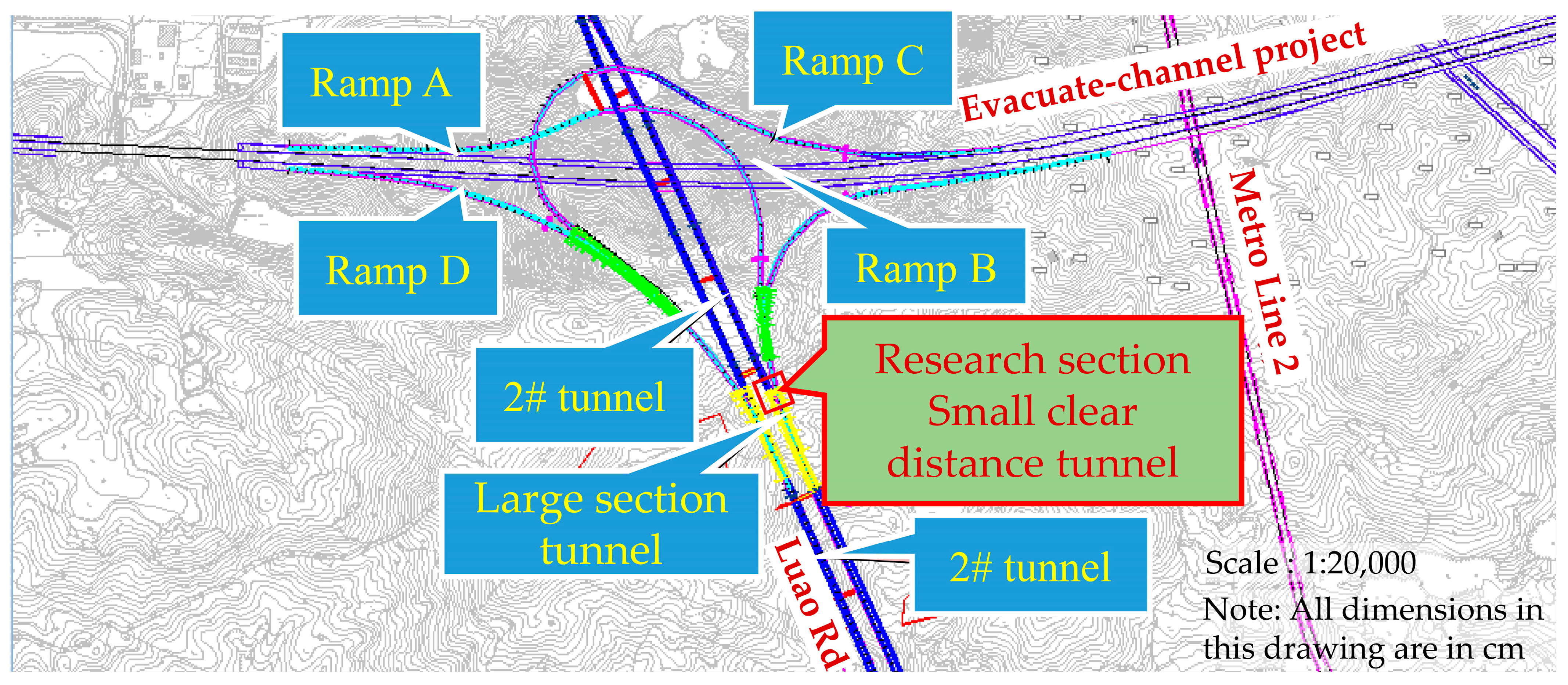
The Xiamen Haicang Evacuation Channel is located in the Haicang District, Xiamen City. The research section is a LuShu interchange in the project. There are four ramps in the interchange, which is a semi-interchange. As shown in Figure 3, the research section is a small clear-distance section of the left line of tunnel #2 and ramp A. The small clear-distance section of tunnel #2 of the main line is ZK2+665–ZK2+775, and the small clear-distance section of the ramp is AK1+600–AK1+490, 110 m long. The excavation span of mainline tunnel #2 and ramp A is 14 m. The research section mainly passes through the second intrusive granite stratum in the late Yanshan period, which is moderately weathered and belongs to Grade III surrounding rock. It is relatively complete rock. It is a deeply buried tunnel in the mountains, with a depth of nearly 100 m.

Numerical Model Establishment

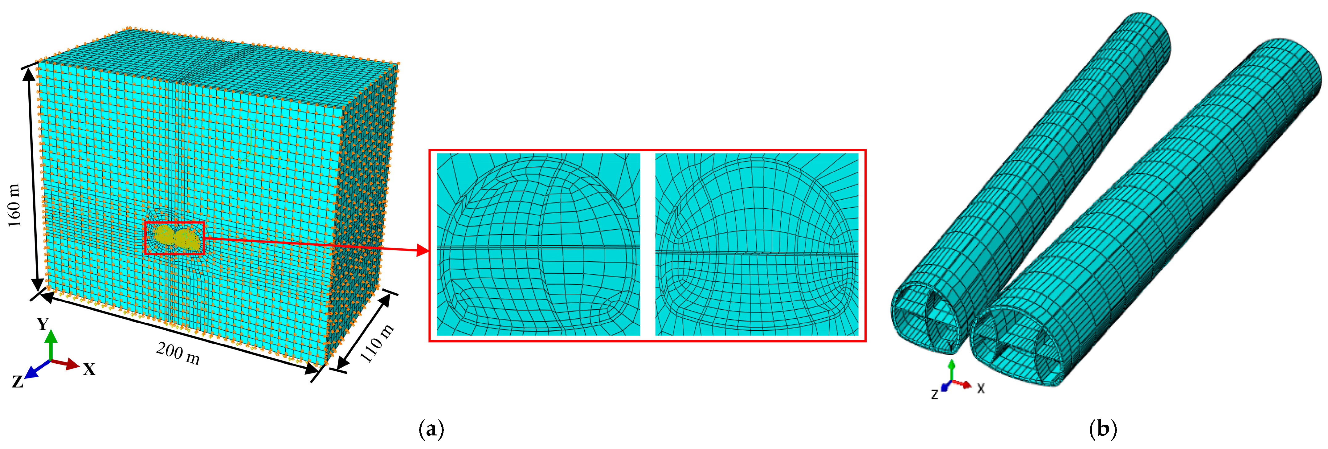
The influence range of the excavation stress is normally 3–5 times of the tunnel radius. A numerical model with a length of 200 m in the X direction, a width of 110 m in the Z direction, and a height of 160 m in the Y direction was established in Abaqus software. The tunnels were located in the position with a depth of 100 m and distance of 60 m to the bottom. The main line tunnel section was set parallel to the axis Z, and the ramp tunnel section was extended horizontally with an angle of 8.28° to Z axis. The two tunnels transitioned gradually from small clear distances to separate tunnels. The length of the research section was 110 m, and the clear distance between the two tunnels ranged from 1.6 to 17.6 m. In the numerical model, the eight-node reduced integration solid element (C3D8R) was used to simulate the strata, tunnel, initial lining, secondary lining, and temporary support. The thickness of the initial lining solid unit was 20 cm, the temporary support was mainly I-steel, the thickness of the solid elements was 18 cm, and the thickness of the secondary lining solid elements was 40 cm. A hexahedral mesh was used to divide the model, and local mesh encryption was performed for the tunnel excavation section. The numerical model was subdivided into 117,355 elements (Figure 4a). The numerical models of primary lining, secondary lining, and temporary support are shown in Figure 4b. The front, back, two sides, and bottom surfaces of the model were constrained by normal displacement, and the front excavation face and top surface were not constrained.
According to a survey report, the rock mass of the small clear-distance tunnel section was Grade III. The physical and mechanical parameters of the rock mass and lining in the numerical simulation were determined by referring to the Specifications for Design of Highway Tunnels [34], as listed in Table 9. The mechanical behavior of the rock mass conformed to the Mohr–Coulomb failure criterion, and the lining structure was an elastomer.
To comprehensively analyze the quantification of the width–span ratio index of the middle rock pillar, four excavation schemes, namely, the full section, step, center diaphragm (CD) method, and double wall heading method were simulated in the numerical simulation [35,36,37,38]. In each excavation scheme, the main line tunnel was advance excavated with a footage of 5 m, and the staggering distance between the main line and the ramp tunnels was 15 m. In the simulation process, the geostress was balanced first, and then the rock mass excavation and lining were simulated step by step. Static analysis was adopted throughout the whole numerical simulation process.

Numerical Model Validation

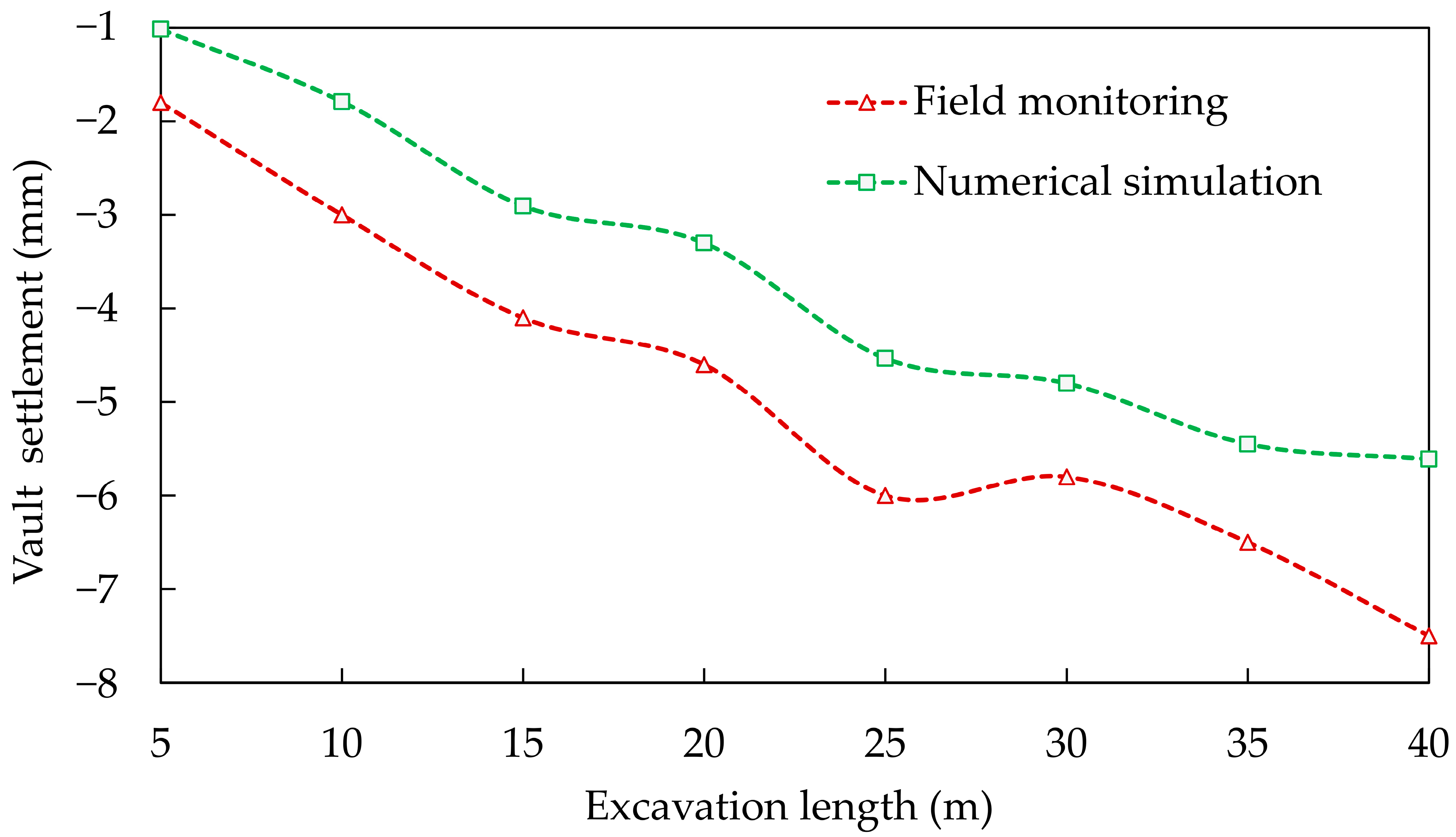
The vault settlement of main line tunnel was used to verify the numerical model. The excavation footage in the numerical model was 5 m. The footage in site excavation was 4–4.6 m/d. Therefore, each excavation footage of the numerical model corresponded to one day of excavation footage on site. The ZK2+665 mileage section of the main tunnel was selected as the monitoring section. The simulated vault settlements were verified with the observation (Figure 5). The maximum difference between the simulated value and the observed one was 1~2 mm, the results of which were relatively close. The observed value and the simulated value of vault settlement were both in the rapid deformation stage. The numerical simulation values were smaller than the measured ones due to the large mechanical disturbance, blasting, and the change in rock mass properties caused by groundwater, etc.

Numerical Simulation Analysis

To describe the stability in the middle region of the full-length middle rock pillar, a target section was selected every 5 m along the tunnel excavation direction, with 23 target sections numbered 1–23. Additionally, a monitoring point was set at the middle position of the middle rock pillar on each target section, as shown in Figure 1.
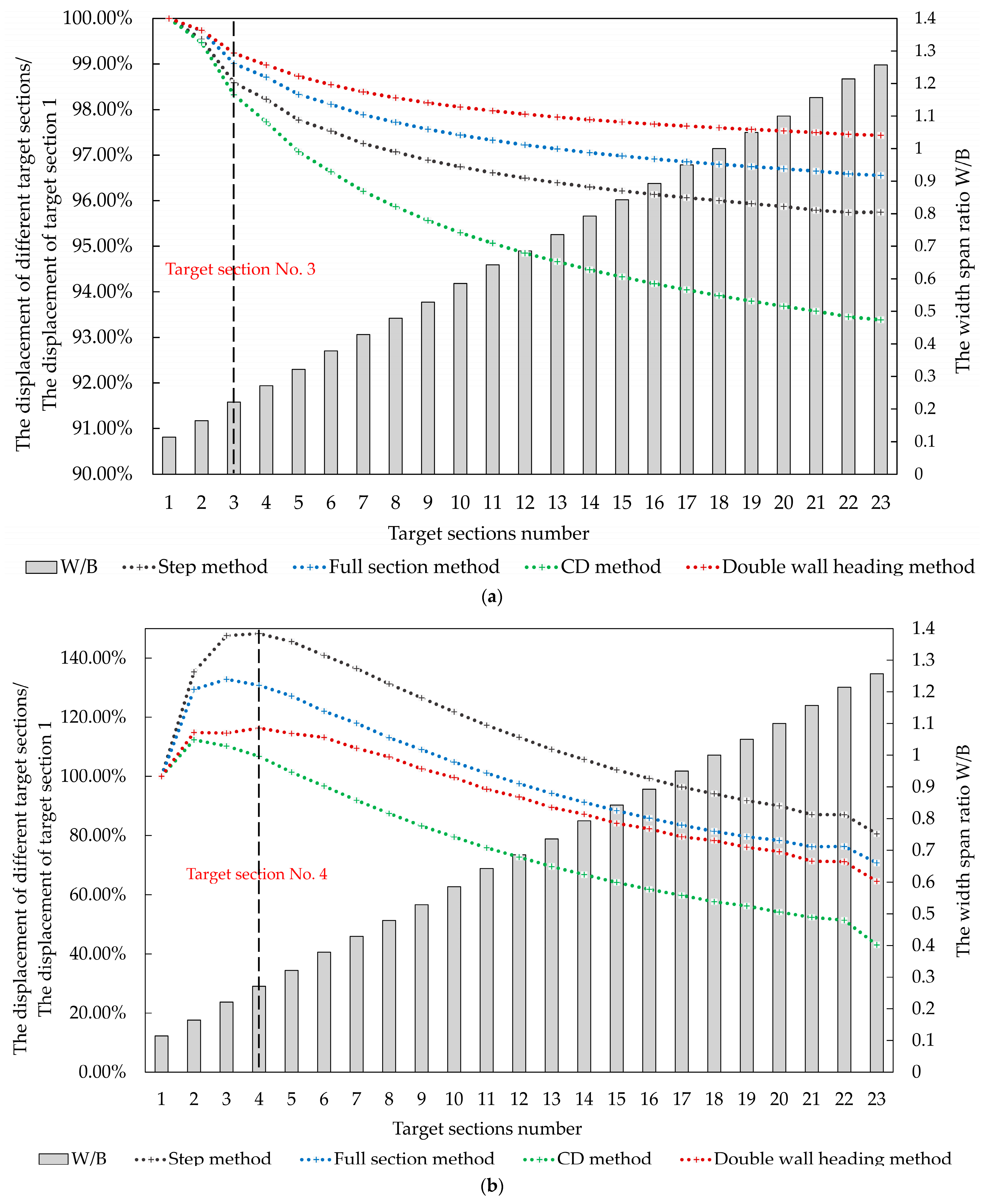
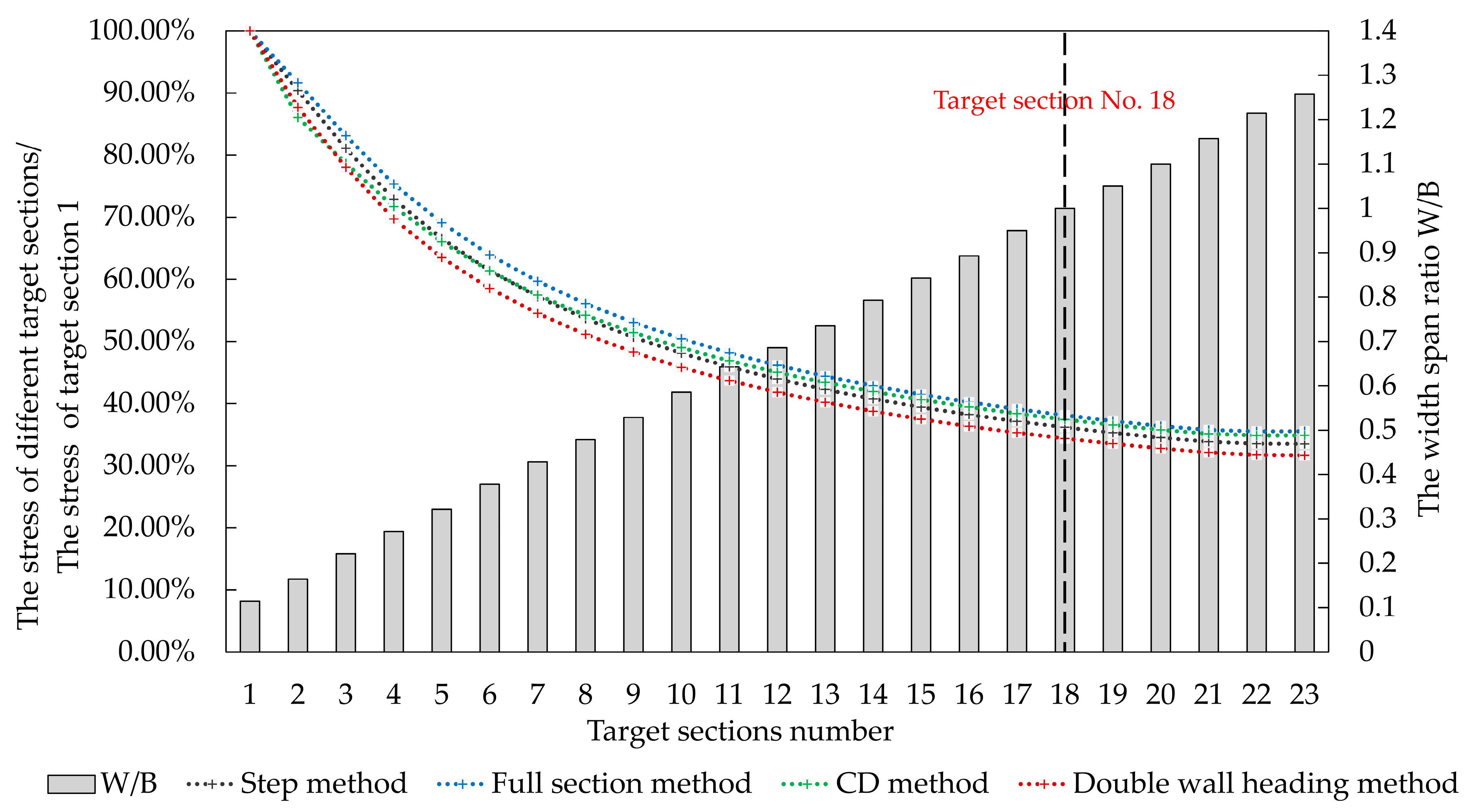
Figure 6 shows the percentage of displacement of the measuring points on different target planes (different width–span ratios) compared with that of the measuring points on target Section No. 1 (tunnel entrance). The left coordinate axis in the figure is the percentage of displacement of measuring points on different target sections and the displacement of measuring points on target Section No. 1; the four curves correspond to different excavation schemes. The right coordinate axis is the specific value of the width–span ratio, corresponding to the column of each section. Figure 6a shows that when the vertical displacement of the central area of the middle rock pillar was before target Section No. 3 and the width–span ratio was within 0.11~0.20, the slope of the displacement curve was obviously large, indicating that the range of the width–span ratio had a significant impact on the vertical displacement. Figure 6b shows that the horizontal displacement of the central area of the middle rock pillar increased when the corresponding width span ratio was between 0.11 and 0.27 before target Section No. 4, which was not conducive to the stability of the middle rock pillar, and the width–span ratio was not conducive to the horizontal displacement.
Figure 7 shows the percentage of the stress of the measuring points on different target sections compared with that of the measuring points on target Section No. 1. Before target Section No. 18, when the corresponding width–span ratio was within 0.11~1.00, the slope of the stress curve in the central area gradually decreased, and the influence of the clear distance on the stress value gradually decreased. When the width–span ratio was 1.00, the slope tended to be zero.
Figure 8 shows the percentage of the maximum equivalent plastic strain of the measuring points on different target sections compared to the maximum equivalent plastic strain of the measuring point on target Section No. 1. The maximum equivalent plastic strain appears near target Section No. 5, and the corresponding width–span ratio ranges from 0.11 to 0.32. The maximum curve of the equivalent plastic strain rapidly flattened from a rapidly falling state, and the range of the plastic zone distributed in the central region of the middle rock pillar was significantly reduced or even disappeared.
Based on the above analysis, considering the small clear-distance tunnel of the Haicang Evacuation Channel Project as an example, the width–span ratio of 0.11~1.26 was subdivided into 0.11~0.30, 0.30~1.00, and 1.00~1.26. The plastic zone had a large distribution area within the range of 0.11~0.30, which is the stress and deformation control area that requires special attention.
To comprehensively consider the classification influence caused by a larger clear distance, the index of clear distance in the Guide to the Construction of Proximity Tunnels issued by the Japan Railway Comprehensive Technology Research Institute [39] was referred to, in which the quantitative classification and corresponding score of the width–span ratio are given. When the width–span ratio was greater than 2.5, the deduction score was small; that is, this situation had little impact on the quality of the intermediate rock. When the width–span ratio was less than 1.0, it was the key control area for middle rock pillar deformation, which was divided into two grades, and the deducted score reduced the rock mass grade by one grade. The width–span ratio score, T4, is shown in Table 10.

3.3.3. Combination of Main Structural Plane and Tunnel Axis

Table 3 shows the evaluation method of the combination relationship between the main structural plane of the middle rock pillar and the tunnel axis on both sides, and obtains the comprehensive evaluation score T5 in 27 different cases. By classifying the comprehensive evaluation score between 0.36 and 1.00, the corresponding deduction scores were set for different levels to determine the impact of different axis directions of the two tunnels on the stability of the middle rock pillar, as shown in Table 11.
There was a score deduction from the most unfavorable to the most favorable. It was considered that, in tunnel excavation, even if the direction of the middle rock pillar structural plane was conducive to stability, it increased the weak plane and reduced the effective strength of the rock mass; thus, score deduction was adopted. Simultaneously, in the direction of the most unfavorable structural plane, the deducted score reduced the grade of the rock mass by one level.

3.3.4. Initial Stress State

In the classification of the initial stress state of the middle rock pillar in Table 5, different initial stress states of the middle rock pillar can be obtained according to the strength–stress ratio S of the surrounding rock. Based on these basic properties, the stress environment of the middle rock pillar was corrected for different stress states, and the corresponding deduction was set to obtain the initial stress state score of the middle rock pillar T6 in Table 12.

3.4. Middle Rock Pillar Grade Determination

T1T6 scores were obtained from the classification standard established by the basic and auxiliary indices of the middle rock pillar. The grades of the middle rock pillar were calculated and evaluated according to T1 to T6 scores, and the grades of the middle rock pillar were determined using the following principles and methods:
(1)
Among the basic indices and auxiliary indices of the middle rock pillar, each index was graded by different numerical ranges, and the corresponding scores also had a range. To determine the specific evaluation scores, a linear corresponding method was adopted, that is, if the uniaxial compressive strength Rc was 50 MPa (Table 7). It can be observed that the rock was between 30 and 70 MPa and belonged to general hard rock, and the corresponding score was between 26 and 34. The corresponding linear score value should be 30, that is, T2 is 30.
(2)
The total score of the middle rock pillar, T, is the sum of T1 to T6.
(3)
The total score T reflects the comprehensive value of the various indices of the middle rock pillar. The maximum value of T is 96, which is less than 0 in the most unfavorable case. If T < 0, then it is treated as T = 0.
Based on the above principles and the established classification standard, five middle rock pillar grades (I, II, III, IV, and V) were set, and each grade had a corresponding total score T range. For grade I, the upper limit was the maximum value of 100 determined by the basic index, and then the sum of the minimum values of each auxiliary index, i.e., 4, was subtracted, that is, 96. The lower limit was the minimum value of 84 for extreme integrity and hard rock determined by the basic index, and then the combined value of each score in the four auxiliary indices was subtracted. Considering that the lower limit of rock inclusion in Grade I should include the most favorable situation of the four auxiliary indices, it can also include some favorable indicators of the second gradient among the auxiliary indicators, and the maximum score that could be deducted was 11, that is, 84 − 11 = 73. Therefore, the total score T of grade I ranged from 73 to 96. According to the above ideas, the score range and description corresponding to each level was determined step by step, as shown in Table 13.
The grade obtained using the middle rock pillar classification standard was compared with the grade of the overall surrounding rock in the site construction environment. If the two grades were the same, the middle rock pillar quality of the project was higher. If the grade obtained by the classification standard was lower than that of the overall surrounding rock of the site construction environment, it was necessary to adjust various influencing factors in the construction conditions, as shown in Table 14.

4. Application of Middle Rock Pillar Classification Method

4.1. Engineering Background

The small clear-distance tunnel of the Xiamen Haicang Evacuation Channel Project was selected as the background engineering site to study the application of the middle rock pillar classification standard. The research section was also a small clear-distance section of the left line of tunnel #2 and ramp A, as shown in Figure 3.
According to the survey report, the small clear-distance section intruded into the granite stratum for the second time through the late Yanshan period, with a medium coarse grain structure and massive structure. It is moderately weathered, with relatively developed joints and cracks. The main joints are along N10–39°E/65–85°S. Some cracks were filled with quartz veins, and the rock mass was relatively intact. Groundwater is rock fissure water, which is mainly stored in granite joints and fissures. The normal water inflow was 63 m3/d, and the water permeability was generally small. Water inrush caused by tectonic fissure water may adversely affect the project. The integrity coefficient Kv = 0.74 was obtained from the borehole data.

4.2. Application of Middle Rock Pillar Classification Standard

The scores of each index were evaluated using the existing survey data according to the site conditions of the project in the research section.
From the borehole data, it can be seen that the integrity coefficient Kv was 0.74, and it can be seen from Table 6 that it was a relative integrity middle rock pillar. Using the integrity coefficient linearly corresponding to the score, T1 = (34 − 26)/(0.8 − 0.6) × (0.74 − 0.6) + 26 = 31.6.
The middle rock pillar consisted of granite strata. According to the survey report, the uniaxial compressive strength Rc was 93.61 MPa, and it can be seen from Table 7 that it is relatively hard rock. Through linear correspondence of the hardness degree to the score, T2 = (42 − 34)/(120 − 70) × (93.61 − 70) + 34 = 37.78.
The normal water inflow in the research area was 4.375 L/min × 10 m, and the maximum water inflow was 13.19 L/min × 10 m. It can be seen from Table 8 that the permeability score T3 was in the range of −4 to 2, and T3 was taken as −4.
The minimum width of the middle rock pillar in the research section was 1.6 m, and the span of the mainline and ramp A was 14 m. Therefore, the width–span ratio at the most dangerous location was W/B = 0.11. As shown in Table 10, T4 was −16.
According to a survey report, the main joint direction of the research section was N10–39 °E/65–85 °S. The included angle between the structural plane and the left tunnel axis was 0°–30°, and the included angle between the structural plane and the right tunnel axis was 60°–90°. The dip angle of the structural plane was 60°–90°. Therefore, the comprehensive evaluation score was 0.60. As shown in Table 11, T5 ranged from −5 to −3, and T5 was taken as −5.
To calculate the initial stress score of the middle rock pillar, the initial strength–stress ratio should first be determined according to Equation (3). According to the survey report, Rc = 93.61 MPa, the gravity of granite formation γ was 26 kN/m3, and the burial depth of the middle rock pillar was H = 100 m, namely, σmax = γ∙H = 26 × 100 = 2600 kN/m3; thus, the initial strength–stress ratio was S = Rcmax = 93,610/2600 = 36.00. According to Table 12, it belongs to the low-stress state, and the corresponding score T6 = −2.
Based on the above analysis, the total score T and the corresponding grade of the middle rock pillar can be determined, as listed in Table 15.
According to Table 13, the middle rock pillar is classified as Grade III. However, moderately weathered granite was present in this area, and its uniaxial compressive strength Rc was 60–70 MPa. After calculation, it belonged to Grade IV, that is, the total middle rock pillar in this section belonged to Grade III–IV surrounding rock, which was lower than the Grade III surrounding rock in the original design scheme. The reason for the decrease in the grading was that the low strength of the moderately weathered granite area in this section and the minimum width–span ratio (0–0.3) evaluated belonged to the range of great mutual influence, so the middle rock pillar in this section belonged to Grade IV. With the excavation of the two tunnels, the clear distance gradually increased, and the width–span ratio also increased. When the width–span ratio was greater than 0.3, the interaction between the two tunnels decreased, and the deducted score decreased. The grade of the middle rock pillar increased to Grade III. Therefore, relevant measures such as reducing footage, reducing the staggered distance between two tunnels, and increasing temporary support measures should be taken in the Grade IV section to ensure the construction safety of medium rock inclusion and play an early warning role in the construction to avoid potential safety hazards.

5. Conclusions

To study the classification method of middle rock pillars in small clear-distance tunnels, the selection of a classification index, establishment of a classification standard, and evaluation of middle rock pillars were carried out, which provided a basis for the evaluation of middle rock pillar quality at the engineering site.
(1)
Six indices affecting the quality of the middle rock pillar were selected in terms of three aspects: geometric, physical, and mechanical factors, including the integrity, hardness, combination of the main structural planes of the middle rock pillar and tunnel axis, permeability, initial stress state, and geometric state.
(2)
The classification index system of the middle rock pillar was established from the two dimensions of the basic and auxiliary indices. Basic indices include integrity coefficient and uniaxial compressive strength. Auxiliary indices include permeability, width–span ratio, combination of main structural plane and tunnel axis, and initial stress state.
(3)
The scoring method of subtracting the score of the auxiliary index on the basis of the score determined by the basic index can more accurately reflect the quality of the middle rock pillar quality.
(4)
According to the score calculated from the evaluation of the middle rock pillar classification standard, the middle rock pillar was divided into five grades: I, II, III, IV, and V.
(5)
The improved classification standard solved the uncertainty problem caused by discrete rock mass parameters and subjective human factors, and the research results provided support for tunnel construction design and support parameter optimization.

Author Contributions

Conceptualization, J.W.; methodology, J.W. and Z.W.; software, Z.W.; validation, L.L., Z.L., J.W., A.C., H.L., Y.S. and X.L. (Xuezeng Liu); formal analysis, J.W. and Z.W.; investigation, J.W., X.L. (Xiaotian Liu), A.C., H.L. and Y.S.; resources, J.W.; data curation, Z.W.; writing—original draft preparation, J.W., Z.W. and A.C.; writing—review and editing, J.W. and A.C.; project administration, L.L. and Z.L. All authors have read and agreed to the published version of the manuscript.

Funding

This research was funded by the Shanghai Municipal Science and Technology Project (18DZ1201301; 19DZ1200900); Xiamen Road and Bridge Group (XM2017-TZ0151; XM2017-TZ0117); the project of Key Laboratory of Impact and Safety Engineering (Ningbo University), Ministry of Education (CJ202101); Shanghai Municipal Science and Technology Major Project (2021SHZDZX0100) and the Fundamental Research Funds for the Central Universities; Key Laboratory of Land Subsidence Monitoring and Prevention, Ministry of Natural Resources of the People’s Republic of China (No. KLLSMP202101; KLLSMP202201); Suzhou Rail Transit Line 1 Co., Ltd. (SURT01YJ1S10002); China Railway 15 Bureau Group Co., Ltd. (CR15CG-XLDYH7-2019-GC01).

Institutional Review Board Statement

The study did not require ethical approval.

Informed Consent Statement

The study did not involve humans.

Data Availability Statement

The data presented in this study are available upon request from the corresponding author.

Conflicts of Interest

The authors declare no conflict of interest.

References

  1. Zheng, H.B.; Li, P.F.; Ma, G.W. Stability analysis of the middle soil pillar for asymmetric parallel tunnels by using model testing and numerical simulations. Tunn. Undergr. Sp. Tech. 2021, 108, 103686. [Google Scholar] [CrossRef]
  2. Li, S.H.; Li, P.F.; Zhang, M.J. Analysis of additional stress for a curved shield tunnel. Tunn. Undergr. Sp. Tech. 2021, 107, 103675. [Google Scholar] [CrossRef]
  3. Dai, S.S. Study on surrounding rock classification and parameter acquisition method of mountain highway tunnel. J. Catastropho. 2019, 34, 77–81. [Google Scholar] [CrossRef]
  4. Chandar, K.R.; Deo, S.N.; Baliga, A.J. Prediction of Bond’s work index from field measurable rock properties. Int. J. Miner. Process. 2016, 157, 134–144. [Google Scholar] [CrossRef]
  5. Lin, Y.M. Theory and Practice of Rock Classification; Metallurgical Industry Press: Beijing, China, 1996. [Google Scholar]
  6. Chen, C.Y.; Wang, G.R. Discussion on the interrelation of various rock mass quality classification systems at home and abroad. Chin. J. Rock Mech. Eng. 2002, 21, 1894–1900. [Google Scholar] [CrossRef]
  7. Barton, N.R.; Lien, R.; Lunde, J. Engineering Classification of Rock Masses for the Design of Tunnel Support. Rock Mech. Rock Eng. 1974, 6, 189–236. [Google Scholar] [CrossRef]
  8. Barton, N.R. Some new Q-value correlations to assist in site characterisation and tunnel design. Int. J. Rock Mech. Min. 2002, 39, 185–216. [Google Scholar] [CrossRef]
  9. Laubscher, D.H. Class distinction in rock masses. 2T Coal Gold, Base Miner. S. Afr. 1975, 13, 37–50. [Google Scholar] [CrossRef]
  10. Laubscher, D.H. A geomechanics classification system for the rating of rock mass in mine design. J. S. Atr. Inst. Min. Metal. 1990, 90, 257–273. [Google Scholar]
  11. Laubscher, D.H.; Jakubec, J. The MRMR rock mass rating classification system in mining practice. MassMin 2000, 7, 413–421. [Google Scholar]
  12. Wang, S.C.; He, F.L.; Li, C.S. Rock Mass Classification of Tunnel Engineering; Southwest Jiaotong University Press: Chengdu, China, 2006. [Google Scholar]
  13. Cai, M.F. Rock Mechanics and Engineering; Science Press: Beijing, China, 2000. [Google Scholar]
  14. GB/T 50218-94; National Standard of the People’s Republic of China. Standard for Engineering Classification of Rock Masses. China Building Industry Press: Beijing, China, 1995.
  15. TB 10003-99; Industrial Standard of the People’s Republic of China. Code for Design on Tunnel of Railway. China Railway Press: Beijing, China, 1999.
  16. JTG D70-2004; Industrial Standard of the People’s Republic of China. Code for Design of Road Tunnel. China Communications Press: Beijing, China, 2004.
  17. JTG F60-2009; Industrial Standard of the People’s Republic of China. Technical Specifications for Construction of Highway Tunnel. China Communications Press: Beijing, China, 2009.
  18. GB/T 50218-2014; National Standard of the People’s Republic of China. Standard for Engineering Classification of Rock Mass. China Planning Press: Beijing, China, 2014.
  19. Peng, N.; Gan, L.K. Fuzzy comprehensive evaluation method in rock classification of in-situ expansion tunnel. Adv. Mater. Resear. 2011, 261–263, 1567–1572. [Google Scholar] [CrossRef]
  20. Duan, L.D.; Song, C.B. Application of BP Neural Network in the Rapid Classification of Surrounding Rock. China Saf. Sci. J. 2010, 20, 41–45+177. [Google Scholar] [CrossRef]
  21. Liang, H.R.; Wang, Y.D.; Peng, H.; Liu, J.F.; Yan, X. Classification of Soft Surrounding Rock of Tunnel Based on Normal Cloud Theory. J. Chongqing Jiaotong Univ. 2021, 40, 82–87. [Google Scholar] [CrossRef]
  22. Yang, G.; Li, T.B.; Ma, C.C.; Meng, L.B.; Zhang, H.G.; Ma, J.J. Intelligent rating method of tunnel surrounding rock based on one-dimensional convolutional neural network. J. Intell. Fuzzy Syst. 2022, 42, 2451–2469. [Google Scholar] [CrossRef]
  23. Ma, J.J.; Li, T.B.; Li, X.; Zhou, S.L.; Ma, C.C.; Wei, D.Q.; Dai, K.K. A probability prediction method for the classification of surrounding rock quality of tunnels with incomplete data using Bayesian networks. Sci. Rep. 2022, 12, 19846. [Google Scholar] [CrossRef]
  24. Xue, Y.G.; Li, Z.Q.; Qiu, D.H.; Zhang, L.W.; Zhao, Y.; Zhang, X.L.; Zhou, B.H. Classification model for surrounding rock based on the pca-ideal point method: An engineering application. Bull. Eng. Geol. Environ. 2019, 78, 3627–3635. [Google Scholar] [CrossRef]
  25. Pan, Y.; Chen, L.; Wang, J.; Ma, H.S.; Cai, S.L.; Pu, S.K.; Duan, J.L.; Gao, L.; Li, E.B. Research on deformation prediction of tunnel surrounding rock using the model combining firefly algorithm and nonlinear auto-regressive dynamic neural network. Eng. Comput. 2021, 37, 1443–1453. [Google Scholar] [CrossRef]
  26. Jiang, F.; He, P.; Wang, G.; Zheng, C.C.; Xiao, Z.Y.; Wu, Y.; Lv, Z.H. Q-method optimization of tunnel surrounding rock classification by fuzzy reasoning model and support vector machine. Soft Comput.—A Fusion Found. Methodol. Appl. 2022, 1–14. [Google Scholar] [CrossRef]
  27. Niu, W.; Li, T.; Xiong, G.; Zhang, G. Support vector machines based intelligent rock mass classification method. J. Eng. Geol. 2011, 19, 88–92. [Google Scholar] [CrossRef]
  28. Liu, H.X.; Li, W.S.; Zha, Z.Y.; Jiang., W.J.; Xu, T. Method for surrounding rock mass classification of highway tunnels based on deep learning technology. Chin. J. Geotech. Eng. 2018, 40, 1809–1817. [Google Scholar] [CrossRef]
  29. Jiang, Q.; Song, S.G.; Li, T.; Wang, K.; Gu, R.H. Study on Surrounding Rock Stability of Small Clear-Distance Twin Highway Tunnel with Eight Lanes. Geotech. Geol. Eng. 2019, 37, 593–598. [Google Scholar] [CrossRef]
  30. Gong, J.W.; Xia, C.C.; Lei, X.W. Analysis of filed measurement and theoretical calculation on rock pressure in shallow buried twin tunnels with small spacing. Chin. J. Rock Mech. Eng. 2010, 29 (Suppl. S2), 4139–4145. [Google Scholar]
  31. Zhang, W.G.; Anthony, T.C. Numerical study of pillar stresses and interaction effects for twin rock caverns. Int. J. Numer. Anal. Met. 2014, 39, 193–206. [Google Scholar] [CrossRef]
  32. GB50287–2016; National standard of the People’s Republic of China. Code for Hydropower Engineering Geological Investigation. China Planning Press: Beijing, China, 2016.
  33. TB 10003-2016; Industrial Standard of the People’s Republic of China. Code for Design on Tunnel of Railway. China Railway Press: Beijing, China, 2016.
  34. JTG 3370. 1-2018; Industrial Standard of the People’s Republic of China. Specifications for Design of Highway Tunnels Section 1 Civil Engineering. China Communications Press: Beijing, China, 2018.
  35. Li, S.B.; Zhang, Y.G.; Cao, M.Y.; Wang, Z.N. Study on Excavation Sequence of Pilot Tunnels for a Rectangular Tunnel Using Numerical Simulation and Field Monitoring Method. Rock Mech. Rock Eng. 2022, 55, 3507–3523. [Google Scholar] [CrossRef]
  36. Yong, Z.; He, H.W.; Li, P.F. Key Techniques for the Construction of High-Speed Railway Large-Section Loess Tunnels. Engineering 2018, 4, 254–259. [Google Scholar] [CrossRef]
  37. Wang, H.N.; Utili, S.; Jiang, M.J. An analytical approach for the sequential excavation of axisymmetric lined tunnels in viscoelastic rock. Int. J. Rock Mech. Min. Sci. 2014, 68, 85–106. [Google Scholar] [CrossRef]
  38. Daraei, A.; Zare, S.; Ghorbani, M. A new multi-graph approach for selecting the sequential excavation method of civil tunnels. Tunn. Undergr. Sp. Tech. 2019, 91, 102999. [Google Scholar] [CrossRef]
  39. He, C. Highway Small Clear Distance Tunnel; China Communications Press: Beijing, China, 2015. [Google Scholar]
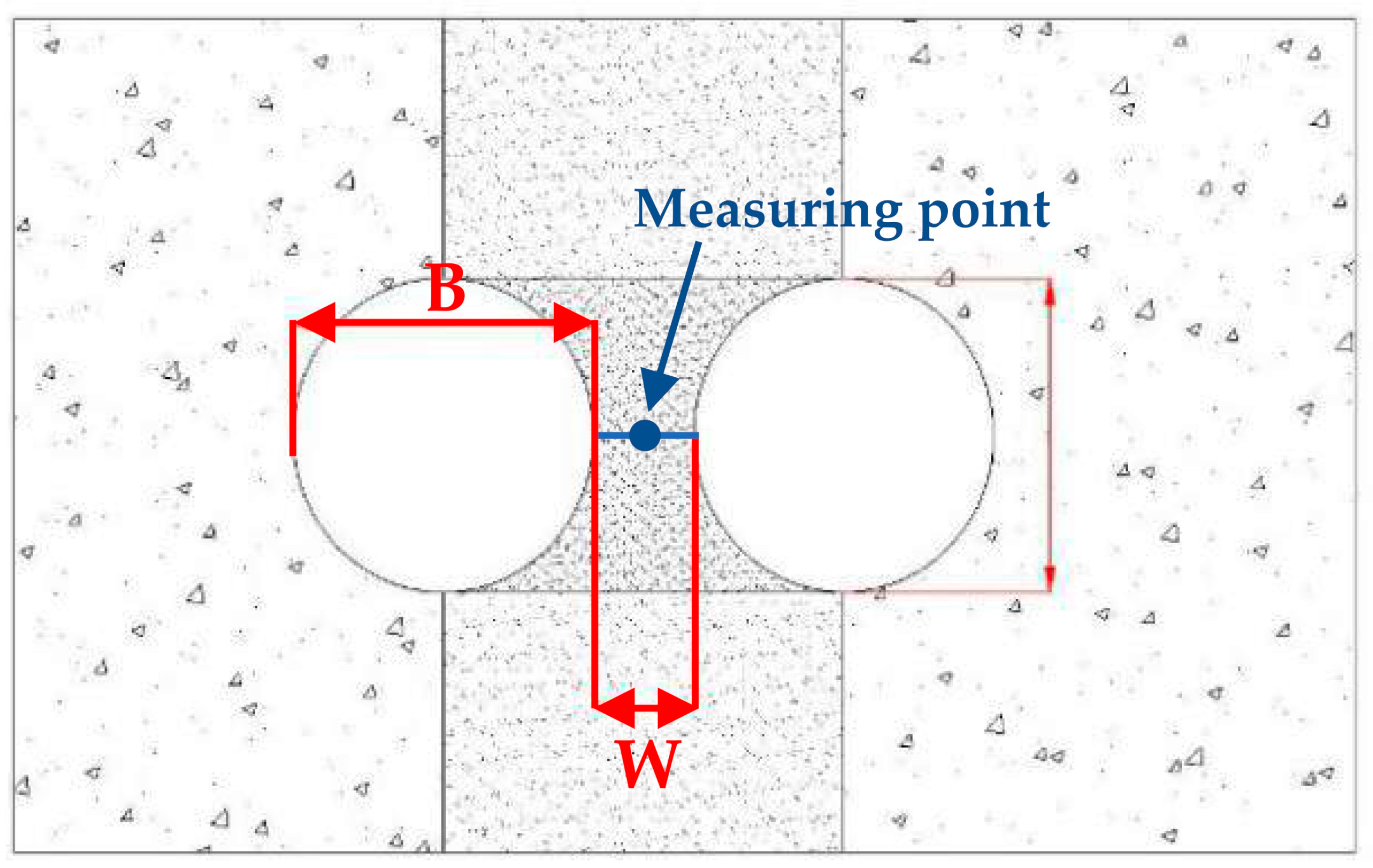
Figure 1. Schematic diagram of the middle rock pillar in a small clear-distance tunnel.
Applsci 13 02130 g001
Figure 2. Proposed middle rock pillar classification index system.
Applsci 13 02130 g002
Figure 3. Research section diagram.
Applsci 13 02130 g003
Figure 4. Numerical calculation model: (a) overall numerical model; (b) tunnel lining.
Applsci 13 02130 g004
Figure 5. Comparison between the measured value and simulated value of the vault settlement.
Applsci 13 02130 g005
Figure 6. Relationship between the displacement and the width–span ratio of the central area of the middle rock pillar: (a) vertical displacement; (b) horizontal displacement.
Applsci 13 02130 g006
Figure 7. Relationship between the stress and the width span ratio of the central area of the middle rock pillar.
Applsci 13 02130 g007
Figure 8. Relationship between the PEEQmax and the width–span ratio of the central area of the middle rock pillar.
Applsci 13 02130 g008
Table 1. Degree of integrity degree (Kv).
Classification BasisIntegrity Degree (Kv)
IntegrityRelative IntegrityRelatively BrokenBroken
Extremely IntegrityMore Integrity
Classification of Tunnel Rock Mass (Ministry of Railways)>0.850.85–0.650.65–0.450.45–0.25<0.25
Classification of Surrounding Rock of Underground Engineering of Hydropower Station (Ministry of Water Resources and Electric Power)>0.750.75~0.450.45~0.2<0.2
Table 2. State distribution of groundwater in the middle rock pillar.
StateDrySlightly DampOccasional Water SeepageFrequent Water SeepageMassive Water Seepage
Water yield (L/min × 10 m)0<1010–2525–125>125
Hydraulic pressure (MPa)00<0.10.1~0.25>0.25
Table 3. Combination relationship between the orientation of the main structural plane and the axis of two adjacent tunnels.
Left Side Tunnel AssessmentRight Side Tunnel AssessmentComprehensive Assessment
Included Angle between Structural Plane Strike and Tunnel AxisInclination of Structural PlaneGrade ScoreIncluded Angle between Structural Plane Strike and Tunnel AxisInclination of Structural PlaneGrade Score
60°–90°60°–90°160°–90°60°–90°11.00
30°–60°0.930°–60°0.90.81
0°–30°0.80°–30°0.80.64
60°–90°60°–90°130°–60°60°–90°0.70.70
30°–60°0.930°–60°0.60.54
0°–30°0.80°–30°0.70.56
60°–90°60°–90°10°–30°60°–90°0.60.60
30°–60°0.930°–60°0.50.45
0°–30°0.80°–30°0.60.48
30°–60°60°–90°0.760°–90°60°–90°10.70
30°–60°0.630°–60°0.90.54
0°–30°0.70°–30°0.80.56
30°–60°60°–90°0.730°–60°60°–90°0.70.49
30°–60°0.630°–60°0.60.36
0°–30°0.70°–30°0.70.49
30°–60°60°–90°0.70°–30°60°–90°0.60.42
30°–60°0.630°–60°0.50.30
0°–30°0.70°–30°0.60.42
0°–30°60°–90°0.660°–90°60°–90°10.60
30°–60°0.530°–60°0.90.45
0°–30°0.60°–30°0.80.48
0°–30°60°–90°0.630°–60°60°–90°0.70.42
30°–60°0.530°–60°0.60.30
0°–30°0.60°–30°0.70.42
0°–30°60°–90°0.60°–30°60°–90°0.60.36
30°–60°0.530°–60°0.50.25
0°–30°0.60°–30°0.60.36
Table 4. Classification of the hardness of the middle rock pillar.
HardnessHard RockSoft Rock
Extremely Hard Relatively HardGeneral Hard General SoftRelatively SoftExtremely Soft
Rc (MPa)>12070–12030–7015–305–15<5
Representative rockUnweathered granite, gneiss, diorite, quartzite, siliceous limestone, etc.Slightly weathered and weakly weathered marble, tuff, dolomite, magmatic rock, etc.Strongly weathered extremely hard rock, weakly weathered hard rock, sandy mudstone, siltstone, mudstone, etc.Mudstone, coal, argillaceous cemented sandstone, conglomerate, etc.Completely weathered rocks
Table 5. Classification of the initial stress state of the middle rock pillar.
Initial Stress State of the Middle Rock PillarMain PhenomenonThe Strength Stress Ratio S
Hard RockSoft Rock
Extremely high stress Excavation may cause rock bursts.
Many new fractures.
The caking phenomenon of rock core.
Sustained large displacement.
<4
Medium~High stress Rock mass peeling and falling off of tunnel wall.
Poor cavern formation.
Significant displacement of tunnel wall rock mass.
Persistent displacement.
4–8
Low stressWeak initial stress state.
The strength of rock mass is conducive to stability.
>8
Table 6. Score of middle rock pillar integrity.
Classification BasisIntegrity Degree
Extremely IntegrityMore IntegrityRelative IntegrityRelatively BrokenMore BrokenExtremely Broken
The rock integrity coefficient Kv>0.90.8~0.90.6~0.80.4~0.60.2~0.4 0.2
Score T142~5034~4226~3418~2610~18 10
Note: The value range “~” includes the value on the right, but excludes the value on the left, that is, “<T1≤”.
Table 7. Score of middle rock pillar hardness degree.
Hardness DegreeHard RockSoft Rock
Extremely Hard Relatively HardGeneral Hard General SoftRelatively SoftExtremely Soft
Rc>12070~12030~7015~305~15 5
Score T242~5034~4226~3418~2610~18 10
Note: The value range “~” includes the value on the right, but excludes the value on the left, that is, “<T2≤”.
Table 8. Score of middle rock pillar permeability.
StateDrySlightly DampOccasional Water SeepageFrequent Water SeepageMassive Water Seepage
Water yield (L/min × 10 m)0 1010~2525~125>125
Hydraulic pressure (MPa)00 0.10.1~0.25>0.25
Score T30−2−4~−2−8~−4−16
Note: The value range “~” includes the value on the right, but excludes the value on the left, that is, “<T3≤”.
Table 9. Material parameters.
MaterialsDensity (kg/m3)Elastic Modulus (GPa)Poisson’s RatioCohesion (MPa)Friction Angle (°)
Surrounding rock2200–23006–100.25–0.32.039–50
Primary lining support2500300.20//
Secondary lining support250032.50.15//
Temporary support79002000.30//
Table 10. Width–span ratio score of the middle rock pillar.
Width Span Ratio W/B 0.3 0.3~1.01.0~1.51.5~22~2.5>2.5
Impact degreeExtremely largeRelatively largeSlightly largeLargeLessSmall
Score T4−16−16~−12−12~−8−8~−4−4~−20
Note: The value range “~” includes the value on the right, but excludes the value on the left, that is, “<T4≤”.
Table 11. Score of the combination of the main structural plane and tunnel axis.
Comprehensive Assessment0.36~0.450.48~0.540.56~0.640.7~1
Influence of middle rock pillar stabilityMost unfavorableUnfavorable~Slightly unfavorableSlightly favorable~FavorableMost favorable
Score T5−16−12~−6−5~−3−2
Note: The value range “~” includes the value on the right, but excludes the value on the left, that is, “<T5≤”.
Table 12. Score of the initial stress state.
The Strength Stress Ratio S 4 4~66~8>8
Initial stress stateExtremely high stressHigh stressMedium stressLow stress
Score T6−16−12~−6−6~−4−2
Note: The value range “~” includes the value on the right, but excludes the value on the left, that is, “<T6≤”.
Table 13. Grade and score range of middle rock pillar.
GradeIIIIIIIVV
Total Score T73 < T ≤ 9657 < T ≤ 7338 < T ≤ 5720 < T ≤ 38T ≤ 20
Basic propertyIntegrityMore integrity~Extremely integrityRelative integrity~More integrityRelatively broken~Relative integrityMore broken~Relatively brokenExtremely broken~More broken
HardnessRelatively
hard~Extremely hard
General hard~Relatively
hard
General soft~General hardRelatively
soft~General soft
Extremely soft~Relatively
soft
Auxiliary propertyPermeabilityDrySlightly dampSlightly damp~Occasional water seepageFrequent water seepage~Frequent water seepageMassive water seepage
Width span ratioExtremely largeRelatively
large
Slightly large~LargeLess~SmallSmall
Combination of main structural plane and tunnel axisMost unfavorableMost unfavorableUnfavorable~Slightly unfavorableSlightly favorable~FavorableMost favorable
Initial stress stateLow stress~Medium stressLow stress~Medium stressLow stress~High stressHigh stress~Extremely high stressHigh stress~Extremely high stress
Table 14. Adjustment of various influencing factors of construction due to the downgrading of the middle rock pillar.
Influencing Factors of ConstructionAdjustmentInfluencing Factors of ConstructionAdjustment
Excavation schemeAdopt the reinforcement scheme with temporary supportFootageReduce footage
Stagger distance of tunnel faceReduce the stagger distance of the tunnel faceStagger distance between two tunnelsReduce the stagger distance between two tunnels
Excavation sequenceWhen the conditions are met, the ramp shall be excavated firstAdvanced reinforcement measuresOpposed anchors and grouting
Table 15. Middle rock pillar score.
IndexT1T2T3T4T5T6T
Score31.637.78−4−16−5−242.38
Disclaimer/Publisher’s Note: The statements, opinions and data contained in all publications are solely those of the individual author(s) and contributor(s) and not of MDPI and/or the editor(s). MDPI and/or the editor(s) disclaim responsibility for any injury to people or property resulting from any ideas, methods, instructions or products referred to in the content.