Article

Numerical Analysis of Frost Heave and Thaw Settlement for Pipeline Buried in Frost-Susceptible Soil via Thermosiphons

Department of Convergence Study on the Ocean Science and Technology, Korea Maritime and Ocean University, Busan 49112, Republic of Korea
*
Author to whom correspondence should be addressed.
Appl. Sci. 2023, 13(3), 1948; https://doi.org/10.3390/app13031948
Submission received: 25 November 2022 / Revised: 29 December 2022 / Accepted: 1 February 2023 / Published: 2 February 2023

Abstract

:
Seasonal frost or permafrost soils may encounter frost heave or thaw settlement resulting from atmospheric temperature changes and/or heat emanating from the resource-carrying pipeline. Notably, these soil movements can damage the pipeline. Thus, various ground stabilization methods have been developed to prevent the onset of these phenomena in frost-susceptible soils, and the application of thermosiphons is a representative method. Recently, a numerical analysis method called the thermosiphon model for a pipeline and thermosiphons in frost-susceptible soil has been developed; however, the study only focused on the ability to reduce frost heave of the soil using the thermosiphon. Therefore, here, numerical analysis was conducted to determine the performance of a buried pipeline according to frost heave and thaw settlement by applying the thermosiphon model via ABAQUS. For the novel numerical analysis, two scenarios are established: frost heave and thaw settlement. For each scenario, the behaviors of the frost-susceptible soil and pipeline are compared in four cases, distinguished by the arrangement of thermosiphons applied. The results indicate that according to the arrangement of the thermosiphons, the frost-heave and thaw-settlement behaviors are verifiably reduced by up to 62% and 82%, respectively, compared to when no thermosiphons are applied.

1. Introduction

Frost heave and thaw settlement in soils result from seasonal temperature changes or the heat emanating from a ground installation in cold regions featuring permafrost or seasonally frozen soil. The phenomenon of frost heave is caused by an expansion in the soil volume due to the formation of ice lenses, which, in turn, is caused by the continuous movement and subsequent freezing of pore water. Conversely, thaw settlement is caused by a decrease in the ground volume due to the melting of the ice lenses. Frost-susceptible soil is vulnerable to frost, which can cause structural instability such as buckling in subterranean pipelines and subsidence of paved roads [1].
Several numerical analyses have been conducted on the behavior of frost-susceptible soils, and various frost-heave models for such soils, such as the segregation potential (SP), FROST, PC-Heave, and thermomechanical (TM)-type models, have been proposed [2,3,4,5,6,7]. Additionally, studies have investigated the soil–structure interactions. Selvadurai et al. [8] compared the behavior of a pipeline buried in frost-susceptible soil, previously investigated in a large-scale laboratory experiment performed by Dallimore [9], with their numerical analysis results [8,9]. Similarly, Ming et al. [10] compared the settlement data of the Qinghai–Tibet highway embankment, as measured in a study by Peng et al. [11], using their numerical analysis results [10,11]. Furthermore, numerous methods have been suggested and utilized for ground stability, including changing the burial depth of the pipeline, backfilling with soil, or involving additional devices such as thermosiphons [12]. Thermosiphons are feasible for various structures, such as pavements, foundations, and transportation pipelines, in cold regions featuring permafrost or seasonally frozen soil. This mitigation device functions based on a circulation mechanism in which the absorbed refrigerant evaporates to a gaseous state, condenses back to its liquid form in the condensing process upon exposure to the atmosphere, and descends into the siphon [13]. Additionally, the internal refrigerant functions via two-phase flow, which has been studied through computational fluid dynamics (CFD). For example, in the studies conducted by Alizadehdakhel et al. [14], Fadhl et al. [15], and Jafari et al. [16], laboratory experiments were compared with simulations performed in Fluent, a commercial fluid analysis program. Such fluid analyses require an enormous amount of time due to the complex calculations of two-phase flow; it is difficult to apply the analysis to the ground behavior with thermosiphons. Therefore, several studies have aimed to simplify the thermosiphon operation and apply it to the numerical analysis. Abdalla et al. [17,18] and Xu et al. [19] developed a thermosiphon model that describes the thermal conductivity according to the heat flux using USDFLD, which is an internal user subroutine of ABAQUS. However, the model used the arbitrary thermal conductivity of the thermosiphon; therefore, no experimental verification could be conducted. Park et al. [12,20] presented a thermosiphon model using DFLUX, an ABAQUS internal user subroutine, and verified it with the results of laboratory experiments [21,22].
However, these studies solely considered the behavior of the frost heave of the ground with the thermosiphon, and the thaw settlement was not considered. In addition, these studies did not characterize the behavior of structures, such as buried pipelines featuring thermosiphons. Therefore, in this study, a numerical analysis was performed on the frost heave and thaw settlement of the ground and the behavior of a buried pipeline in accordance with the thermosiphon–ground interaction. Because there is a lack of experimental studies on the behavior of a buried pipeline according to the thermosiphon–soil interaction, the numerical analysis was performed with the verified frost-heave model and thermosiphon model. The former was applied in accordance with the methodology of Zhang et al. [23], and the latter referenced the study of Park et al. [20], which were coded in the internal user subroutine of ABAQUS. Because the thermosiphon model [20] was verified with the experimental result of a small-scale thermosiphon, the numerical analysis scenarios in this study were also constructed by referring to the small-scale laboratory model experiment of Huang et al. [24] by modifying the specifications and boundary conditions. The numerical analysis of this study primarily comprised two ground-behavior scenarios: The first scenario investigated frost heave, where the entire ground was set to a temperature exceeding 0 °C; subsequently, the surface temperature was set below 0 °C to induce frost heave in the soil surrounding the pipeline. The second scenario investigated thaw settlement, where the internal temperature of the pipeline was increased, thereby leading to melting and settling of the frost-susceptible soil and resulting in sinking behavior in the pipeline. In the two scenarios, to confirm the behavior of the ground and the buried pipeline with the thermosiphons, a total of eight cases was analyzed by setting four cases per scenario depending on the presence or absence of the thermosiphon and their different arrangements.

2. Frost-Heave Model and Thermosiphon Model

In this study, the frost heave and thermosiphon models were used to confirm the behavior of a buried pipeline according to the frost heave and thaw settlement of frost-susceptible soil with the application of a thermosiphon. First, the thermomechanical (TM)-type frost-heave model was used [7,23,25]. Second, the thermosiphon model was utilized as a boundary condition, thereby defining the performance of the thermosiphons and the heat flux according to the temperature difference between the atmosphere and ground [20]. These models are detailed in the following sub-sections.

2.1. TM Model: Unfrozen Water Content of Soil

The unfrozen water content represents the pore water inside the soil that does not freeze even if the soil freezes. The tendency of the unfrozen water content is to decrease as the temperature drops, and its residual amount varies depending on the type of soil. These aspects are illustrated in Figure 1 [26].
The aforementioned tendency of the unfrozen water content is manifested as the frost heave characteristic of the soil. Sand having a particle size as shown in Figure 1a has large pores and low capillary pressure, so the pore water cannot be continuously supplied after freezing begins. Therefore, as shown in Figure 1b, the unfrozen water is rapidly decreased and converged, and the formation of ice lenses is severely restricted. Conversely, for silt or silty clay with relatively high capillary pressures, the tendency of the unfrozen water content to decrease is moderate due to the sufficient movement of pore water; therefore, the ice lens develops adequately. Soils that allow ice lenses to develop easily are called frost-susceptible soils.
Studies have been conducted to fit the trend of unfrozen water content in frost-susceptible soils into an exponential-trend curve through laboratory experiment data [27], as formulated in Equation (1). As a foundational equation, the unfrozen water content ω can be calculated as
ω =   α * θ β * ,
where α * and β * represent the trend coefficients of the curve according to the type of soil and θ denotes the temperature.
As Equation (1) possesses an infinite value at the freezing point (0 °C), the problem of convergence is encountered in the numerical analysis. To address this problem, Michalowski [7] proposed a trend-based equation characterizing the unfrozen water content, expressed in Equation (2) as
ω = ω * + ( ω ¯ ω * ) e α * ( T T 0 ) ,   [ T < T 0 ] ,
where ω * depicts the unfrozen water content at such a low temperature that the trend of the residual unfrozen water content finally converges, ω ¯ denotes the pore water content at a temperature above 0 °C, α represents the trend coefficient corresponding to the unfrozen water content according to the type of soil, T represents the average temperature, and T 0 symbolizes the freezing-point temperature (0 °C).

2.2. TM Model: Porosity Rate Function

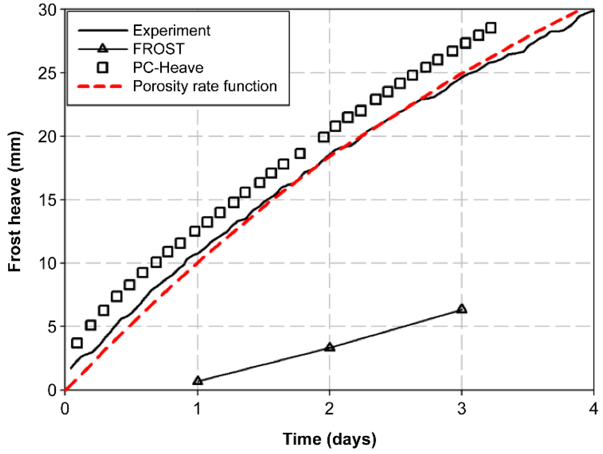
The typical frost-heave models of frost-susceptible soils include the SP, FROST, PC-Heave, and TM-type porosity rate function models. The comparison between each model and the corresponding laboratory–model test results are illustrated in Figure 2 [28]. In this comparison study, Henry’s [29] laboratory experiment was compared with each frost-heave model; the laboratory experiment was conducted using a 150 mm soil sample by applying temperatures of −1.4 °C and 0.7 °C to the top and bottom of the sample, respectively. Observably, among the models compared with the laboratory-derived experimental results, the PC-Heave and porosity rate function models can optimally simulate the frost heave of the soil.
The frost-heave model employed in this study is the porosity rate function, which is a TM-type model that defines the frost expansion of the soil according to the changing porosity rate with a change in temperature. The core function of the porosity rate function is as follows:
n ˙ = n ˙ m g T ( T T 0 T m ) 2   ·   e 1 ( T T 0 T m ) 2 ,
where n ˙ m implies the maximum growth rate of the porosity, T m and g T depict the temperature and temperature gradient at the maximum porosity growth rate ( n ˙ m ), respectively, and n ˙ m / g T possesses a constant value depending on the type of soil [23].
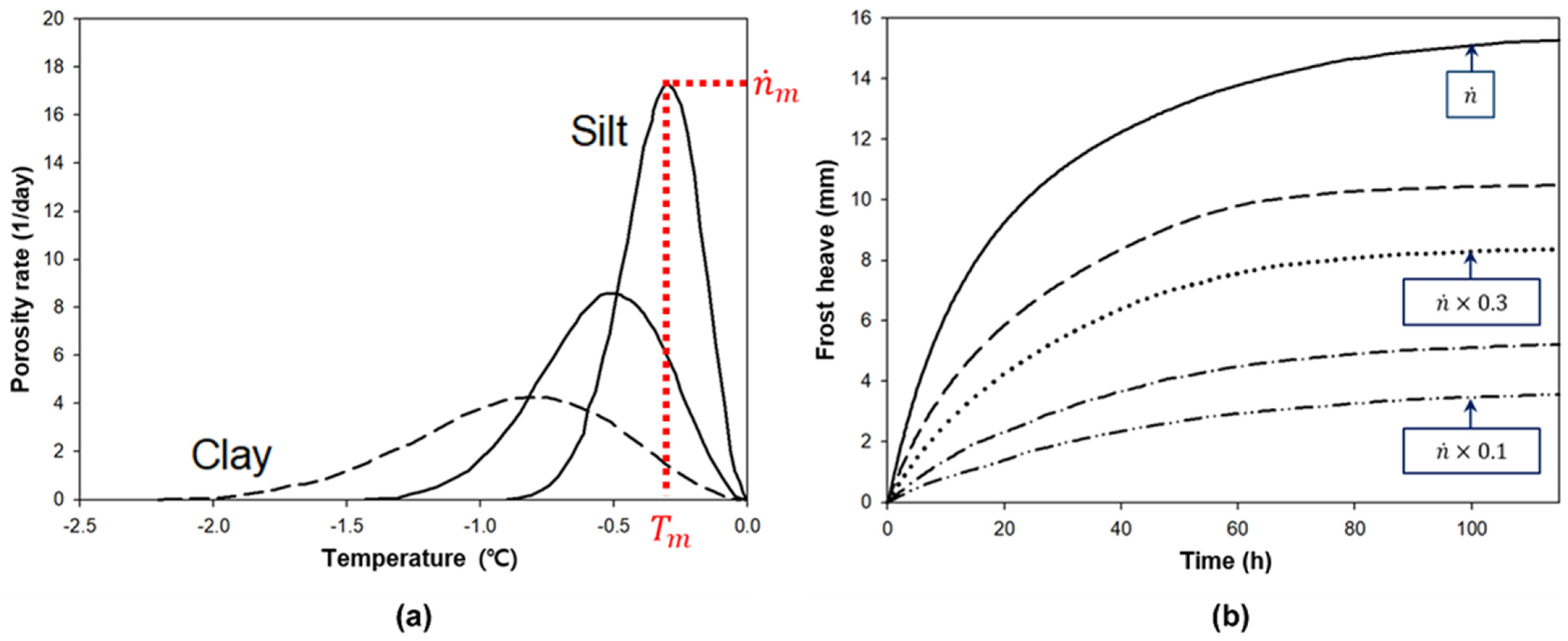
The porosity rate ( n ˙ ) tends to vary depending on the type of soil, as illustrated in Figure 3a [25]. As shown in Figure 3a, the maximum porosity growth rate ( n ˙ m ) of silt tends to be greater than that of clay. This maximum porosity growth rate is the key value that determines the frost-heave amount of soil in Equation (3). In Figure 3b, it can be seen that the maximum porosity growth rate affects the maximum frost-heave amount. These results come from numerical analysis in which the maximum porosity growth rate value is arbitrarily changed but the other conditions are set to remain identical.

2.3. TM Model: Constitutive Model

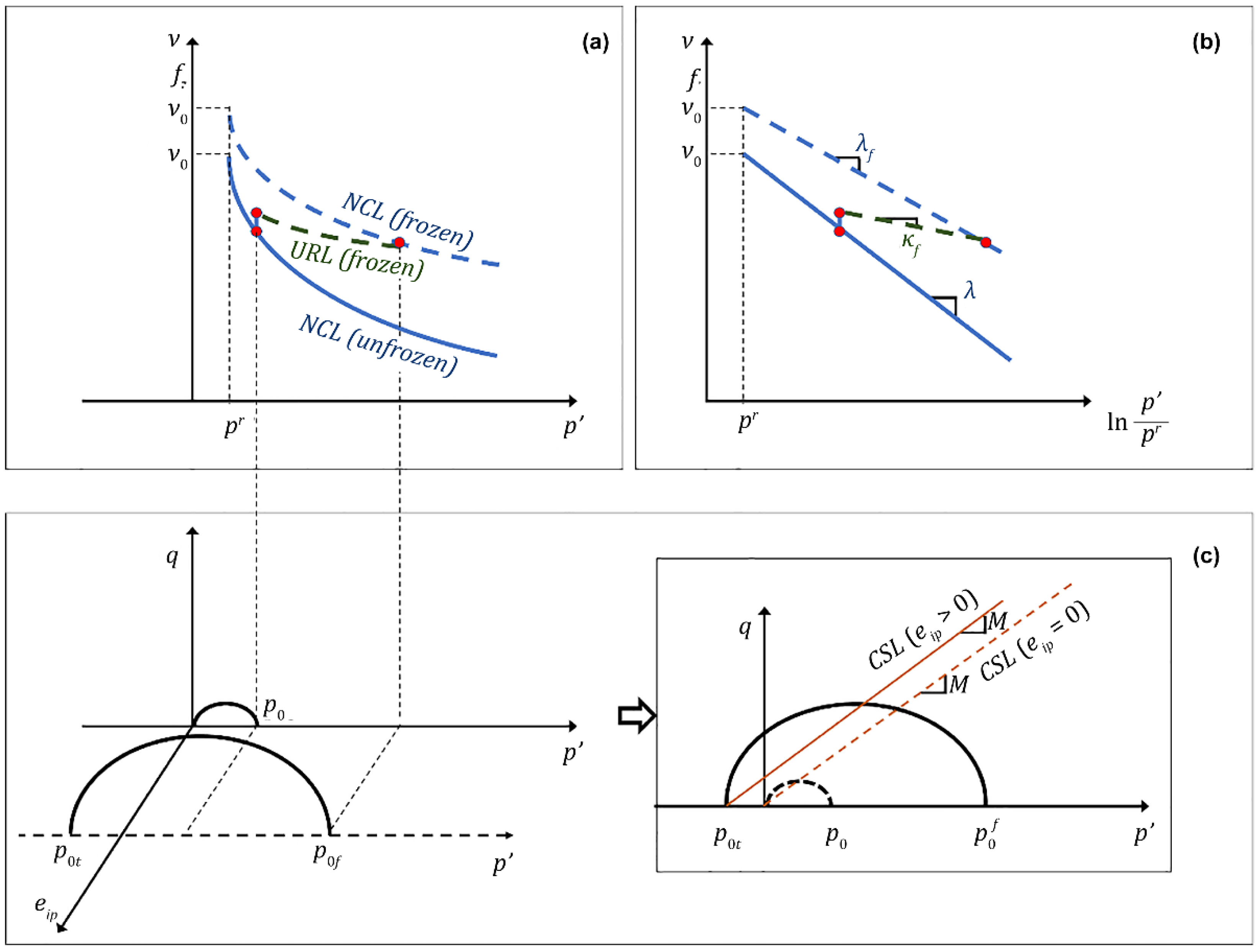
For the constitutive model of the soil, the modified Cam–Clay model formulated by Zhang and Michalowski [23] is employed. Figure 4 defines the normal compression lines (NCLs), unloading–reloading lines (URLs), and elliptical yield surface in the constitutive model when the soil freezes. The pore ice is the key factor changing the stiffness of the frozen soil. Zhang and Michalowski [23] introduced the concept of pore ice ratio ( e i p ) such that NCLs and URLs are defined according to the e i p . The pore ice ratio is defined as the ratio of the void ice volume ( V i p ) to the soil volume ( V s ), and this ratio is expressed in Equation (4) as
e i p = V i p V s = ( ω ¯ ω ) · ρ s ρ w · 1.09 ,
where ρ s and ρ w represent the density of soil and water, respectively.
In accordance with the pore ice ratio ( e i p ), the NCLs and URLs are defined using Equations (5a) and (5b), respectively, as
λ f =   λ e ( α 1 e i p ) ,
κ f = κ e ( α 2 e i p ) ,
where α 1 and α 2 are constant values depending on the type of soil, which can be estimated via isotropic compression tests using a triaxial apparatus [30,31]. Notably, the value of e i p is zero for the soil before freezing; therefore, the NCL is λ f =   λ , and URL is κ f = κ .
The elliptical yield surface is plotted in the q   (deviatoric stress)– p   (effective isotropic stress) plane, as depicted in Figure 4. This surface obeys the following law:
f = q 2 + M 2 ( p p 0 t ) ( p p 0 ) = 0 ,
where M denotes the slope of the critical state line (CSL) in q p space, which is constant regardless of soil freezing. The shape of the elliptical yield surface, as characterized using Equation (6), changes according to the p 0 t and p 0 ( p 0 f ). Equations (7) and (8a,b) define the various variables used in Equation (6) as follows:
p 0 t = p t ( 1 e α 3 e i p ) ,
p 0 f = p r   e ( β e i p ) / ( λ f κ f )   ( p 0 p r ) ( λ κ f ) / ( λ f κ f ) ,
β e i p = ν 0 f ν 0 0.09 e i p ,
where p 0 t denotes the isotropic tensile strength and increases as the pore ice ratio ( e i p ) increases; p 0 depicts the pre-consolidation pressure, which is rendered p 0 f when the soil freezes; p r represents the reference effective isotropic pressure; β denotes the relationship between the specific volume and pore ice ratio ( e i p ); and ν 0 f and ν 0 symbolize the specific volumes of frozen and unfrozen soils at the reference effective isotropic pressure, respectively. Further details on the constitutive model can be obtained in the literature, as reported by Zhang and Michalowski [23].

2.4. Thermosiphon Model

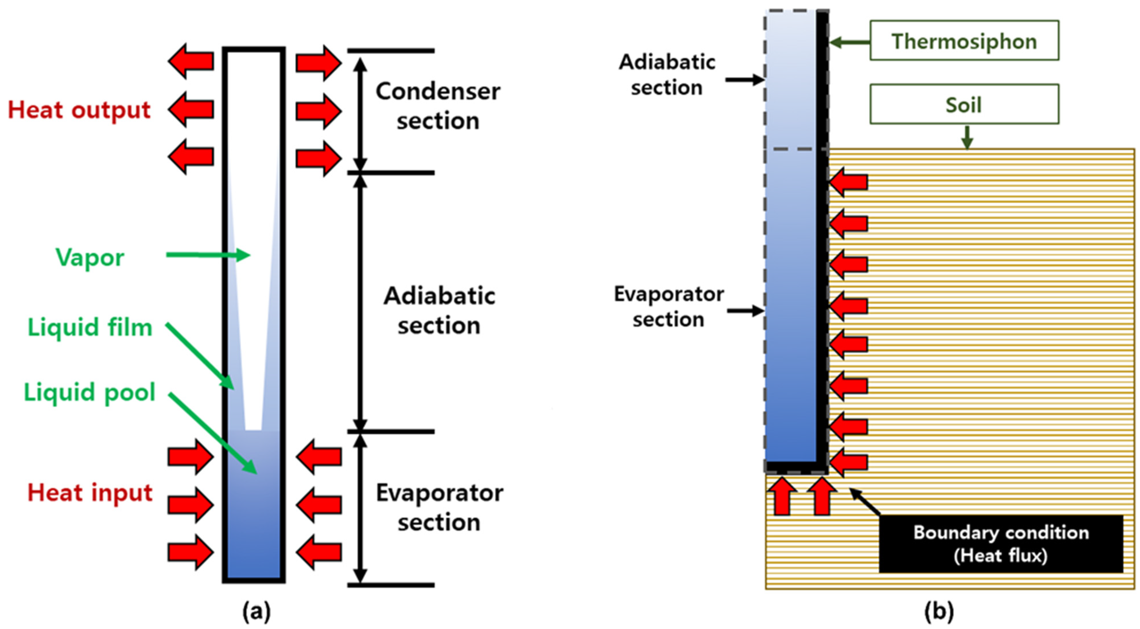
Figure 5a illustrates a thermosiphon—a structure with a mechanism for absorbing heat from the ground via the evaporator section, evaporating the internal refrigerant, condensing the internal refrigerant in the condenser section, and recirculating the coolant to the evaporator section [32]. Such a thermosiphon can be simulated via CFD incorporating two-phase flow; however, this method is complicated and requires considerable time for analyzing the linkage with the ground. Therefore, the thermosiphon model used in this study, as depicted in Figure 5b, applies the heat flux as a boundary condition to the evaporator section of the thermosiphon [12,20]. The heat flux ( q t s , W/m2) and heat flow rate ( Q t s , W) are defined as
q t s = Q t s A t s ,
Q t s = λ t s   L e v p   ( T e v p T a ) ,
where A t s represents the area (m2) of the evaporator section of the thermosiphon. In Equation (9b), λ t s implies the thermal conductivity per unit length of the thermosiphon (W/m K) and represents the performance of the thermosiphon. Additionally, L e v p denotes the length of the evaporator segment of the buried thermosiphon, T e v p symbolizes the temperature of the soil surrounding the evaporator segment, and T a represents the ambient air temperature. The thermosiphon model operates the thermosiphon such that the heat flux represented in Equation (9a) is calculated using the heat flow rate formulated in Equation (9b). Moreover, the thermosiphon model operates by yielding the calculated heat flux when T a < T e v p and halts operation under other conditions.

3. User Subroutine for TM Model

3.1. Component of User Subroutines

Figure 6 presents the ABAQUS internal user subroutines that were used for analysis in this study. The user subroutine, SDVINI, defines the initial state variables, such as porosity and unfrozen water content. Subsequently, the values calculated by other user subroutines are stored in state variables.
The user subroutine UMAT can define the elastic–plastic stress–strain relationship of soil upon freezing and thawing, and the user subroutine UEXPAN defines the thermal strain using the porosity rate function when the soil freezes or thaws. The user subroutine UMATHT determines the volume fraction of the soil components (soil particle, water, ice) using the unfrozen water contents by reflecting the changed porosity and defining the material properties such as density, specific heat, and thermal conductivity. In addition, it determines the latent heat in the apparent heat capacity in the conservation of energy equation and temperature of the soil. These user subroutines exchange the values in the state variables. At each time increment, the state variables are called, calculated, and updated at the end of the time increment for the overall integration points of the element. These updated state variables include the volume fraction of the soil mixture, temperature gradient, stress, and strain. Moreover, these variables are mutually influenced by time increments [33].
The user subroutine DFLUX defines the heat flux at each time increment as a boundary condition in the evaporator segment of the thermosiphon, and the heat flux is determined using Equations (9a) and (9b). The heat flux is calculated through the difference between the ground temperature surrounding the thermosiphon and the ambient air temperature, calculated in time increments via Equation (9b). The operating condition is maintained only when T a < T e v p .

3.2. Implementation of the Constitutive Model in the TM Model

The total strain increment of frost-susceptible soil comprises the elastic–plastic mechanical strain increment ( d ε i j e p ) and thermal strain increment ( d ε i j t h ), which are a result of the increase in the porosity, and these parameters are defined in the user subroutines UMAT and UEXPAN, respectively. The parametric relationship is expressed as follows:
d ε i j = d ε i j e p + d ε i j t h
For calculating d ε i j e p represented in Equation (10), the Jacobian matrix must be defined inside the UMAT. The elastic–plastic constitutive is expressed as
δ σ = C [ 1 ( f σ ) ( f σ ) T C A + ( f σ ) T C ( f σ ) ] δ ε = C e p δ ε ,
where C e p is an elastic–plastic constitutive matrix. Additionally, δ σ represents the stress increment, δ ε denotes the elastic–plastic strain, C depicts the elastic matrix, and f σ represents the flow matrix. Moreover, A symbolizes the hardening modulus, which is given by
A = ( d f d p 0 ) ( ν p 0 λ κ d f d p ) = M 2 ( p 0 t p ) ( 1 + e ) p 0 λ κ M 2 ( 2 p p 0 p 0 t ) ,
where ν represents the specific volume and e denotes the void ratio.
The thermal strain increment ( d ε i j t h ) represented in Equation (10) is calculated with the user subroutine UEXPAN. In the corresponding user subroutine, the increase in the porosity through the porosity rate function, formulated in Equation (3), is defined. The anisotropic formation of an ice lens must be considered before calculating the d ε i j t h . This consideration is achieved by introducing a “growth tensor” [7] as
n ˙ = n ˙ | ξ 0 0 0 ( 1 ξ ) 2 0 0 0 ( 1 ξ ) 2 | ,
where ξ has a value ranging from 0.33 to 1. The lower and upper limits result in isotropically and unidirectionally increasing volumes, respectively. Subsequently, d ε i j t h can be calculated in the x, y, and z coordinates as
{ d ε x t h d ε z t h d ε x z t h } = { m 2 ξ + 0.5 n 2 ( 1 ξ ) n 2 ξ + 0.5 m 2 ( 1 ξ ) m n ( 3 ξ 1 ) } n ˙ d t 1 n ,
where m is c o s θ , n is s i n θ , and θ denotes the angle between the x-axis and the direction of the heat flow.

3.3. Implementation of the Thermal Model for the TM Model

The thermal constitutive characteristics of the material, such as volumetric heat capacity and thermal conductivity, are defined in the user subroutine UMATHT and are dependent on the volume fraction of the components (soil particles, pore water, and ice) constituting the saturated frost-susceptible soil.
Equation (15) represents an energy-balance equation:
( C e q L ρ i θ i T ) T t ( λ e q T ) = 0 ,
where L denotes the latent heat of fusion per unit mass, ρ i symbolizes the density of ice, C e q depicts the volumetric heat capacity of the soil mixture, and λ e q represents the thermal conductivity of the soil mixture. Moreover, the density ( ρ e q ), volumetric heat capacity ( C e q ), and thermal conductivity ( λ e q ) of the soil mixture are calculated as
ρ e q = θ s ρ s + θ w ρ w + θ i ρ i ,
C e q = θ s ρ s c s + θ w ρ w c w + θ i ρ i c i
λ e q = θ s log λ s + θ w log λ w + θ i log λ i ,
where ρ , c , and λ on the right-hand side of Equations (16a)–(16c) imply the density, mass heat capacity, and thermal conductivity, respectively. Additionally, the superscript characters s, w, and i denote the skeleton of soil, pore water, and ice, respectively.
Moreover, θ s , θ w , and θ i symbolize the volumetric fractions of soil, pore water, and ice skeletons, respectively, and are defined as
θ s = V s V = 1 n ,
θ w = V w V = ν n ,
θ i = V i V = ν ( 1 n ) ,
where ν is
ν = V w V w + V i .

4. Finite Element Analysis Method and Results

4.1. Soil Behavior Scenarios and Modeling

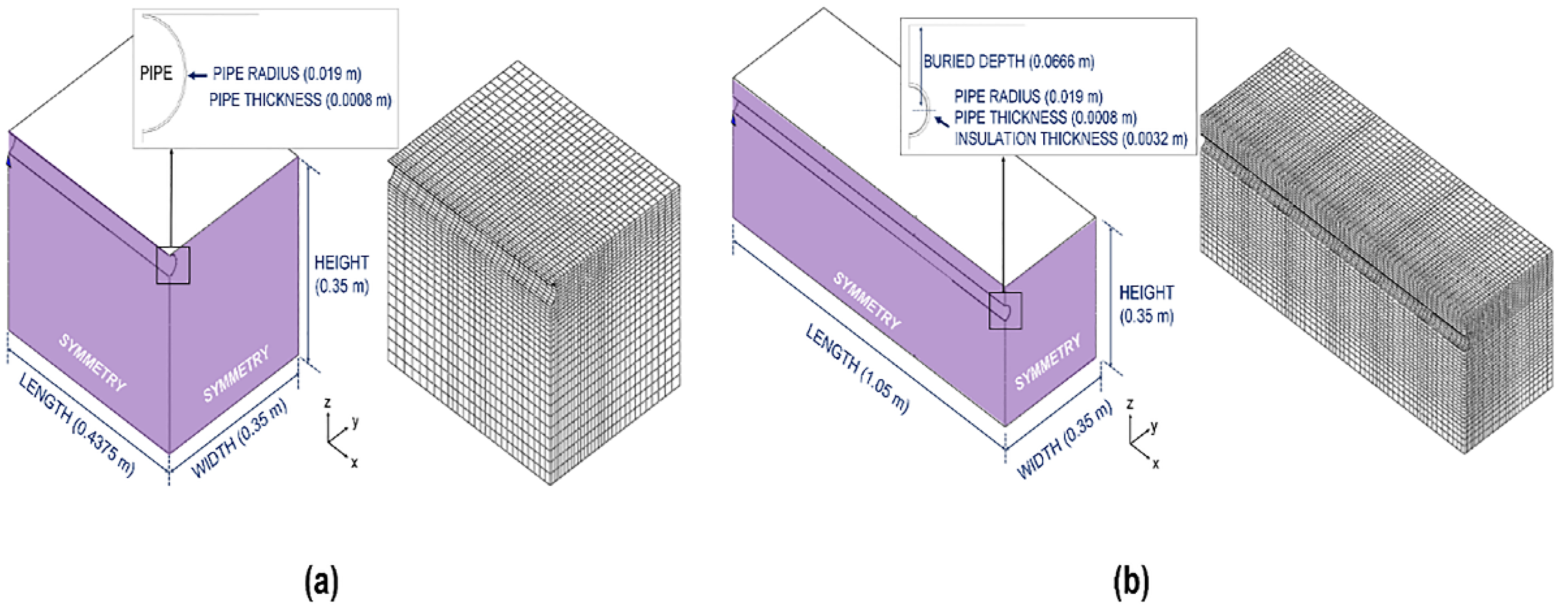
This study is conducted using ABAQUS (version: 2018), a commercial finite element program, to compare the behavior of a pipeline under thermosiphon implementation.
Table 1 lists the two scenarios that are set for analysis. In the first scenario, the frost-heave behavior of the soil and pipeline is examined when the temperature of the entire model is set above 0   ° C ; subsequently, the surface temperature is set below 0   ° C to induce frost heave in the soil surrounding the pipeline. The second scenario is thaw settlement, where the internal temperature of the pipeline is increased, thereby leading to melting and settling of the frost-susceptible soil and resulting in sinking behavior of the pipeline. In each scenario, four cases (total eight cases) are considered based on the number and arrangement of the thermosiphons (Table 1). Because the thermosiphon model [12] was verified with laboratory experimental results of a small-scale thermosiphon, the numerical analysis scenarios of this study were constructed using the same specification of the small thermosiphon.
Accordingly, the soil and pipe configuration were also used with reference to the specifications used in the small laboratory experiment [24]. The specifications of the models in the two scenarios are illustrated in Figure 7. Both scenarios are modeled with symmetry in the width and length directions (purple-colored plane) in Figure 7 for reducing the analysis time. For the displacement boundary condition, the bottom of the soil is fixed in the x, y, and z directions. For the side planes, excluding the symmetry plane, the displacement other than that in the z direction is constrained. For the pipeline, the pin-constraint condition is applied to the ends.
For the thermal boundary condition, the adiabatic condition is applied to the bottom and side planes of the soil. Additionally, the Fourier boundary condition is applied to the top surface for heat exchange through the temperature difference between the ambient (air) temperature and the soil with the convective heat-transfer coefficient (h). For the pipeline, the convective boundary condition is applied to the inside of the pipeline solely in the thaw-settlement scenario, and excessive heat flow is controlled by modeling the insulation layer. For the soil specifications of the two scenarios, the width and depth are identical (0.35 m), but the length is set longer in the thaw-settlement scenario. This is because, in the case of the frost-heave scenario, the heave of the buried pipe occurs due to the pressure caused by the frost heave of the soil; by contrast, in the thaw-settlement scenario, pipe subsidence is primarily caused by the weight of the pipe itself and the soil weight. This allows for a further increase in the pipeline subsidence under the thaw-settlement scenario. Accordingly, the buried depth of the pipeline is also set deeper in the thaw-settlement scenario such that it can be affected more by the soil thaw settlement.
The element used in this numerical analysis is the coupled temperature-displacement trilinear element (8-node). Figure 7 illustrates that the elements are set densely in the vicinity of the pipeline and thermosiphon and the total number of nodes in the model ranges from 28,488 to 77,868, depending on the scenario.
The thermosiphons are modeled with a height of 0.5 m, which is identical to that reported by Park et al. [12]. Accordingly, half the height of the thermosiphon (0.25 m) is modeled as being buried in the soil. Figure 8 illustrates the top view of the thermosiphon arrangement for each case. In both scenarios, the number of thermosiphons in cases A, B, and C are identical: (2 pair × 1), (2 pair × 2), and (2 pair × 3), respectively.
The measurement points set in this study are illustrated in Figure 9. A measurement point is named such that its object and location can be determined. For example, the first letter of the measurement point “S-3-B”, “S”, implies soil, whereas “P” indicates pipeline. The second term, the number “3”, represents the number corresponding to the x-direction in Figure 9a. Notably, the six points are set at an interval of 0.0875 m in the frost-heave scenario. Similarly, seven points are set at an interval of 0.175 m in the thaw-settlement scenario. The letter “B” denotes a point corresponding to the position of the letter in Figure 9b.
For the soil, nine points are set ranging from A to I. Additionally, for the pipeline, 0°, 90°, and 180° points of angle are set instead of letters. Therefore, a total of 54 and 18 measurement points are obtained for the soil and pipeline, respectively, under the frost-heave scenario. Similarly, 63 and 21 measurement points are manifested for the soil and pipeline under the thaw-settlement scenario, respectively. The measured values, such as the unfrozen water content, displacement, and stress, are acquired at these points.
Table 2 lists the material properties and parameters of the soil mixture utilized in this study [23,25,33]. The corresponding parameters of unfrozen water contents and porosity rate function model are calibrated to the experimental results reported by Fukuda et al. [34]. Among the calibrated parameters, compared to that reported in the previous study, the maximum porosity growth rate is reduced ( n ˙ m =   0.33 × 10 5   s 1 ) to prevent excessive frost heave. Zhang and Michalowski [23] also performed their analysis using reduced parameters. They compared the frost-heave amounts of the soil using the existing parameters and reduced parameters featured in this study with the experimental case reported by Fukuda et al. [34].
The pipeline used in this study is a 201 stainless steel pipe with an elastic modulus of 203   GPa [24]. Polyurethane foam, which is the insulation layer of the pipeline used in the thaw-settlement scenario, has a thermal conductivity of 0.02   W / m   K [34]. In addition, a thermosiphon corresponding to a refrigerant filling ratio of 100% is employed with an efficiency of 0.464 W / m   K [20].

4.2. Frost-Heave Scenario

In the frost-heave scenario, after setting the initial temperature of the entire model to 3   ° C , the Fourier boundary condition (−5 ° C ; 5   W / m 2   K ) is applied [35] to the top surface of the model, and analysis is performed until the temperature of the entire model converges to −5 ° C .
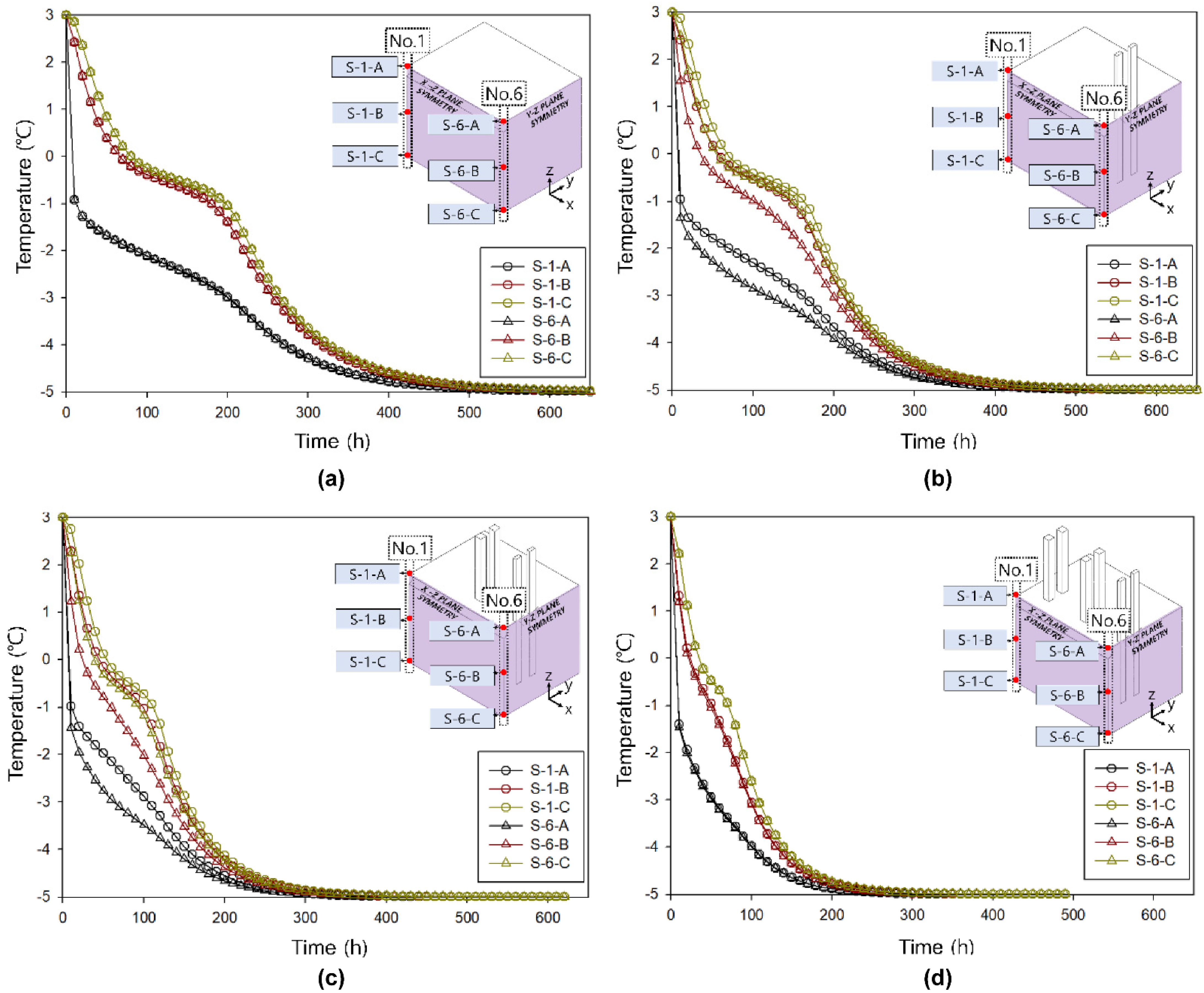
Among the measurement points of the model, the time for the temperature to converge to −5 ° C in “S-1-I”, which experiences the minimum effect from the thermosiphon, is approximately 700 h in CASE_H—the case in which the thermosiphon is not utilized. CASE_HA, CASE_HB, and CASE_HC (scenarios featuring thermosiphons) demonstrate temperature convergence after 590, 440, and 360 h, respectively. Notably, as the number of thermosiphons increases, the temperature converges to −5 ° C at a faster rate, as shown in Figure 10.
Figure 10 also illustrates the graph of the temperature decrease with respect to time measured at x-direction measurement points No. 1 and No. 6 corresponding to z-direction measurement points A, B, and C. For CASE_H, the temperature trends corresponding to the depth measurement points of No. 1 and No. 6 are approximately identical. However, for CASE_HA and CASE_HB, the temperature of measurement point No. 6 decreases faster than that for No. 1, because measurement point No. 6 is greatly affected by the thermosiphon, thereby yielding this trend. However, for CASE_HC, the temperature trends of measurement points No. 1 and No. 6 are similar to those of CASE_H because the effect of the thermosiphon increases at No. 1; this increase is attributed to the thermosiphon placement, as depicted in Figure 10d. The temperature trend of the overall measurement point indicates that CASE_HC, featuring the maximal number of thermosiphons, has a much steeper temperature drop than that observed for CASE_H. These time-dependent temperature trends manifest as the trends corresponding to the unfrozen water content and pore ice ratio, as explained in next figure.
Figure 11 presents a comparison of the results of unfrozen water content and pore ice ratio that are measured at the measurement points “S-1-B” and “S-6-B” for all cases. As the temperature of the measurement point converges to −5 ° C , the unfrozen water content and pore ice ratio converge to 0.160 and 0.357, respectively.
Similar to the temperature trend observed in Figure 10, for CASE_HA and CASE_HB, the measurement point “S-6-B” has a steeper slope compared to that of “S-1-B”; this disparity in steepness demonstrates the effect of the thermosiphon. Additionally, according to the number of thermosiphons applied, CASE_HC converges first, i.e., at the fastest rate, and CASE_H converges last, i.e., at the slowest rate.
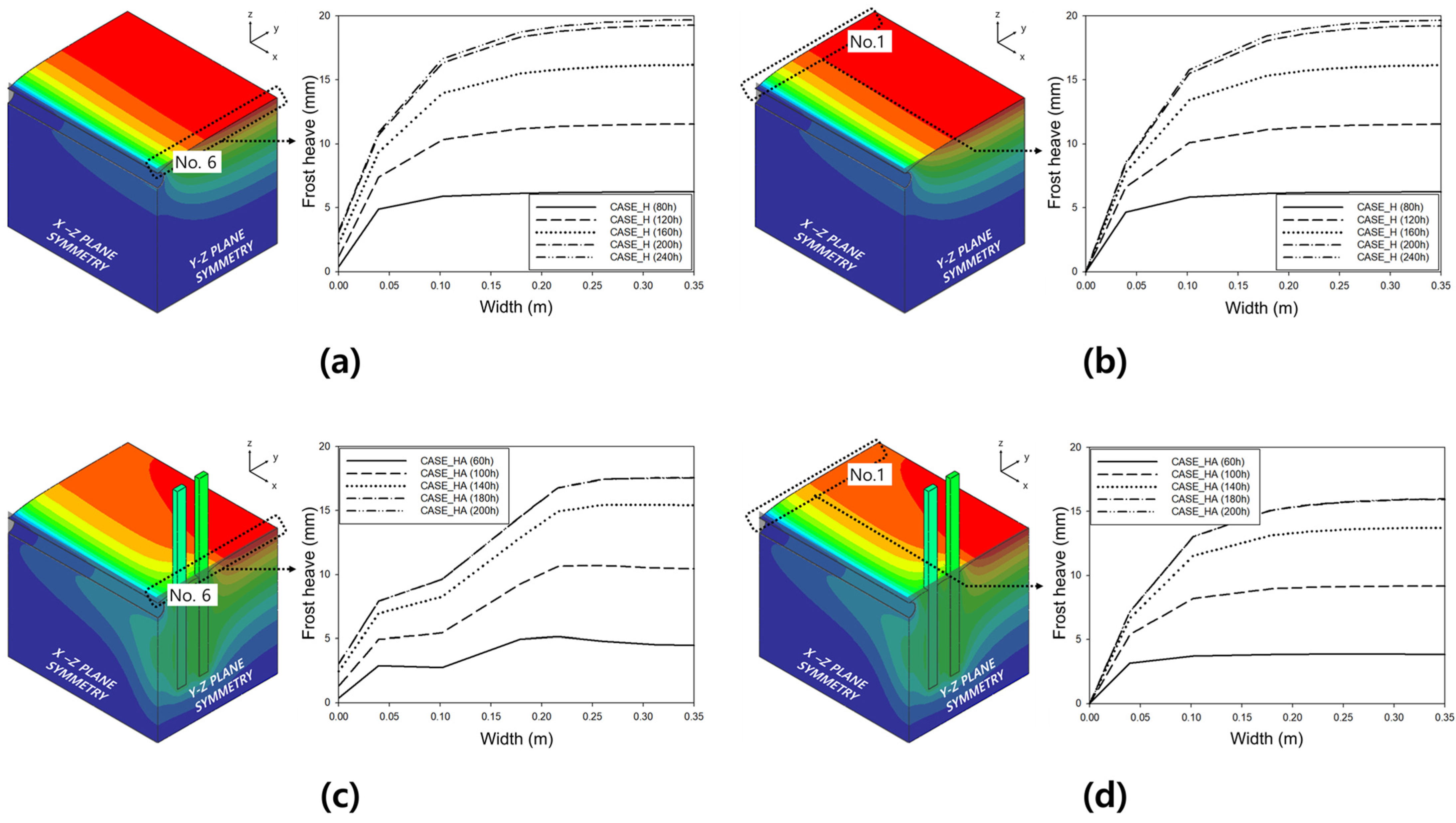
As the temperature of the soil decreases to a certain state, the frost-heave progress ceases at different times and yields the heave amount for each case. Figure 12 indicates the frost-heave trends of the soil surface along the width corresponding to No. 1 and No. 6 of CASE_H and CASE_HA with respect to time. In Figure 12a,b, the frost heave converges at approximately 240 h in CASE_H. In addition, the widths of the soil surface corresponding to No. 1 and No. 6 exhibit almost the same convergence times and heave amounts.
However, in CASE_HA in which thermosiphons are utilized, the results reveal a slightly different trend, as shown in Figure 12c,d. For CASE_HA, the convergence time for the frost heave of the soil surface is 180 h, which implies that the rate of convergence is faster than that for CASE_H. In addition, the frost-heave magnitude of the soil surface is different along the widths at No. 1 and No. 6. These results are clearly attributable to the effect of the thermosiphons. Note that the frost-heave amount of the surface where the thermosiphon is embedded at No. 6 is smaller than that at No. 1, which is located farther away from the thermosiphon.
Similarly, CASE_HB and CASE_HC in which the numbers of thermosiphons are further increased also exhibit comparable frost-heave tendencies. The reduction rates of the frost heave magnitudes corresponding to CASE_HA, CASE_HB, and CASE_HC are 10.8, 36.2, and 55.6%, respectively; this result clearly demonstrates that as the number of thermosiphons increases, the inhibiting effect on the frost heave increases accordingly.
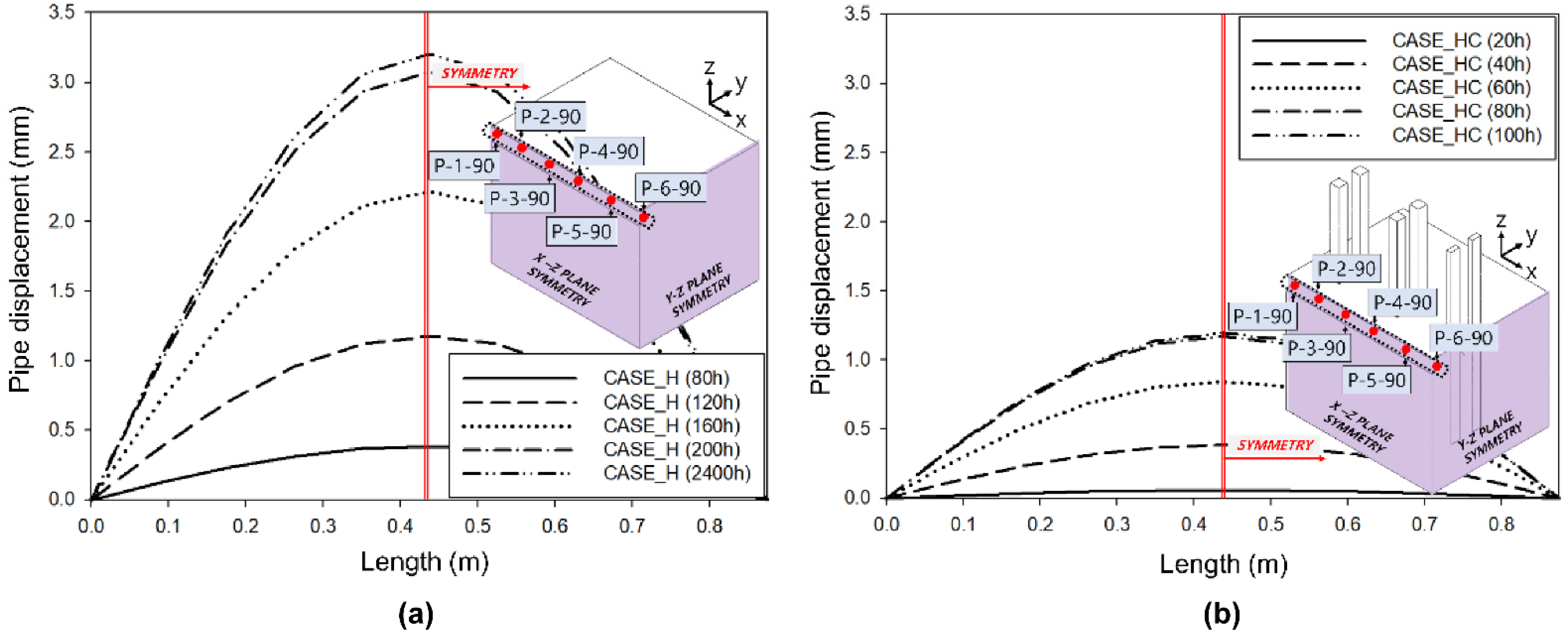
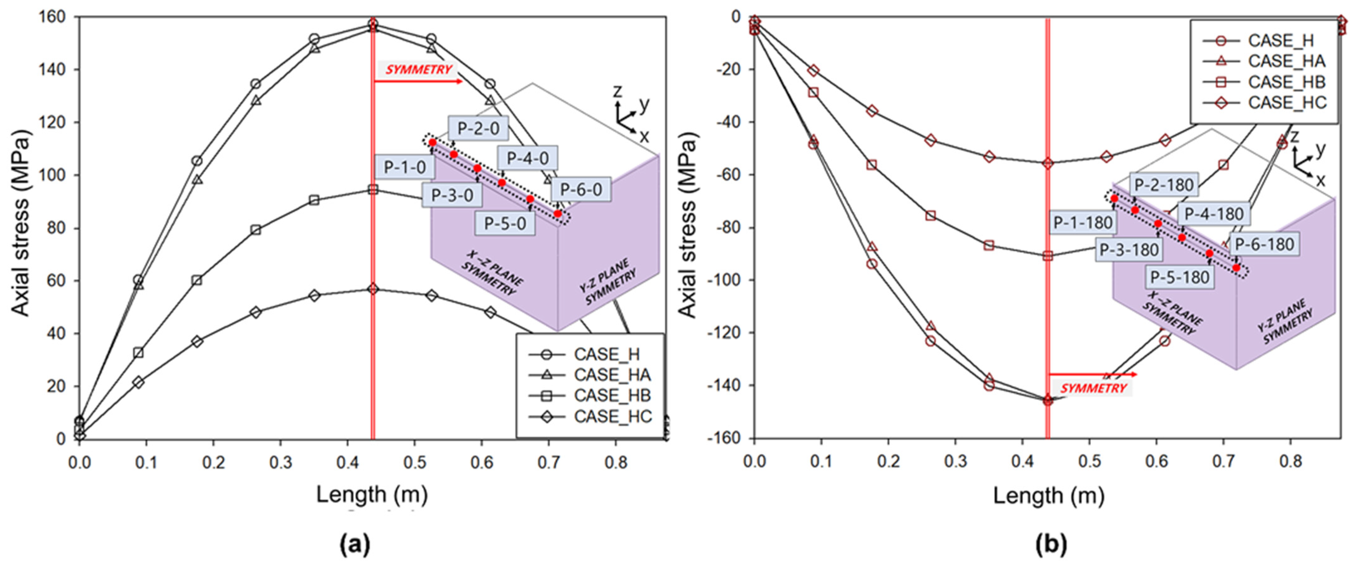
Similar to the frost-heave tendency of the soil surface, the upward displacement tendency of the pipeline is also investigated. Figure 13 graphically demonstrates the displacement of the pipeline as time progresses. The time for the convergence of the pipeline displacement is remarkably similar to that for the frost heave of the soil surface. For CASE_H, it converges at approximately 240 h. Moreover, for CASE_HA, CASE_HB, and CASE_HC, it converges at 180, 140, and 100 h, respectively. The maximum displacement of the pipeline is measured at the measurement point “P-6-90”, and the displacement of the pipeline in CASE_H is approximately 3.2 mm. The displacements of the pipeline in CASE_HA, CASE_HB, and CASE_HC with thermosiphons applied are 3.07, 1.93, and 1.19 mm, respectively. Compared to CASE_H, it is confirmed that the displacement of the pipeline in CASE_HA, CASE_HB, and CASE_HC is reduced by 4.28, 39.77, and 62.71%, respectively. The axial stress of the pipeline increases as the displacement behavior of the pipeline increases, and when the behavior of the pipeline converges, the axial stress of the pipeline converges in tandem. Figure 14 illustrates the axial stresses of all cases measured at the measurement points that are set according to the x-direction of the pipeline. The pipeline behavior according to the frost heave of the soil exhibits the largest axial tension stress (positive stress) at the measurement point “P-6-0” set at the top of the pipeline. Additionally, the largest axial compression stress (negative stress) is observed at the measurement point “P-6-180” set at the bottom of the pipeline.
The magnitude of the axial stress for the pipeline decreases according to the number of thermosiphons applied, which is similar to the displacement of the pipeline. Compared to the maximum axial stress (tension) of CASE_H measured at the measurement point “P-6-0” in Figure 14a, CASE_HA, CASE_HB, and CASE_HC exhibit axial stress reduction rates of 1.06, 39.78, and 63.75%, respectively. Furthermore, Figure 14b, featuring the results of the maximum axial stress (compression), also depicts similar results. The axial stress (compression) reduction rates compared to CASE_H are 0.34, 37.39, and 61.92% in CASE_HA, CASE_HB, and CASE_HC, respectively.

4.3. Thaw-Settlement Scenario

In the thaw-settlement scenario, the internal temperature of the pipeline is increased, thereby leading to melting and settling of the frost-susceptible soil and resulting in sinking behavior of the pipeline.
After setting the initial temperature of the frost-susceptible soil model to −15   ° C , the Fourier boundary condition is applied to the inside surface of the pipeline, where the temperature and convective heat transfer coefficient are set to 60 ° C and 55 W / m 2   K , respectively. The analysis is conducted until the temperature of the entire model converges by gradually increasing the soil temperature around the pipeline. In addition, for the top surface of the soil boundary condition of the model, the Fourier boundary condition is identical to that applied in the frost-heave scenario, and solely the temperature is set differently by changing it to −15 ° C . In this scenario, the initial conditions for the frozen soil are applied, i.e., the initial porosity is set to 0.457. Accordingly, the initial unfrozen water content and pore ice ratio of the soil are set to 0.07859 and 0.5895, respectively.
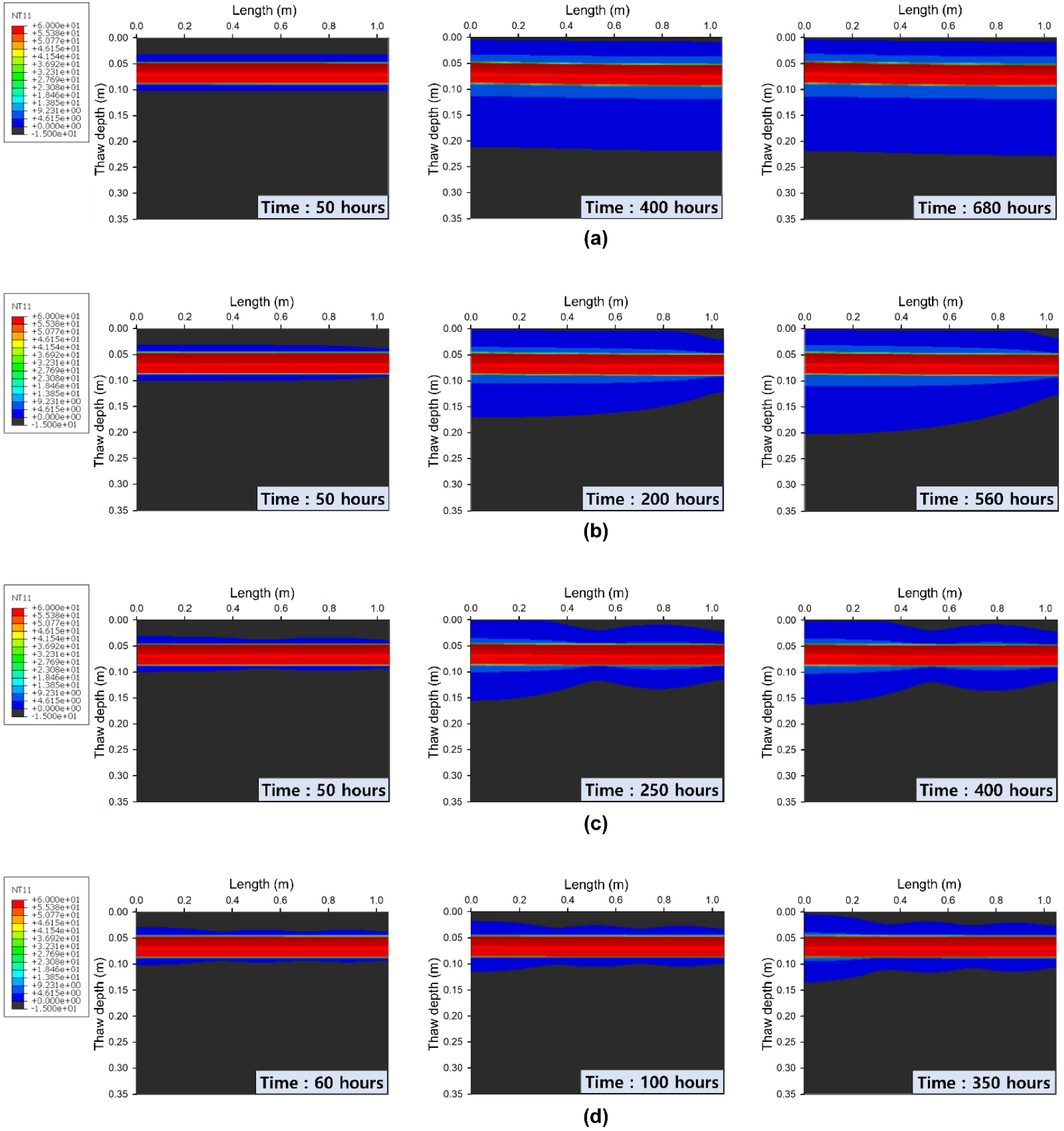
The reference point of the temperature convergence for the entire case is set based on the measurement point “S-1-I”, the farthest point from the thermosiphons and pipeline. Figure 15a depicts the temperature change of the soil with time measured at the point “S-1-I”. Among the analysis cases, CASE_T—the case in which thermosiphons are not utilized—exhibits the largest temperature change and the slowest temperature convergence rate, corresponding to a convergence time of approximately 680 h. Conversely, for CASE_TC, which features the maximal number of thermosiphons, the change in temperature is minimal, and the temperature convergence rate is the fastest, corresponding to a convergence time of approximately 350 h.
This temperature trend induces the trends of unfrozen water content and pore ice ratio, as illustrated in Figure 15b and Figure 15c, respectively. The convergence time trends of unfrozen water content and pore ice ratio for all cases are identical to the convergence time trend of the temperature. In addition, the change ratio of unfrozen water content and pore ice ratio decreases as the number of applied thermosiphons increases. These trends of convergence time show that thermosiphons perform well as the ground stabilization method and it can be confirmed that the performance increases as the number of thermosiphons increases
Additionally, when the temperature of the measurement point “S-1-I” converges, the temperature of the soil around the pipeline increases due to the high temperature of the pipeline. Therefore, the thaw bulb, which refers to the thawed shape of the soil above 0   ° C , forms completely.
Figure 16 demonstrates the evolution of the thaw-penetration depth, which is the maximum depth of the thaw bulb in the x–z symmetry plane. Figure 16a illustrates the result of CASE_T. Notably, an even thaw-penetration depth (0.23 m) is formed according to the length direction.
However, in the cases featuring thermosiphons, the thaw-penetration depth of the soil adjacent to the thermosiphon has a shallow depth due to the effect of the thermosiphon, as indicated in Figure 16b–d. The maximum thaw-penetration depth is observed at No. 1 in the cases featuring thermosiphon application along the length for the point that is furthest from the thermosiphons. Accordingly, the minimum thaw-penetration depth is formed at No. 7. Moreover, the maximum thaw-penetration depths of CASE_TA, CASE_TB, and CASE_TC are 0.205, 0.163, and 0.139 m, respectively, with minimum thaw-penetration depths of 0.129, 0.118, and 0.107 m, respectively. Therefore, as an increasing number of thermosiphons is applied, the thaw-penetration depth is rendered shallower. Therefore, as the ground stabilization method, the thermosiphon plays its role well in reducing the thawing area of the ground under the pipe, and it can be confirmed that the performance of ground stabilization increases as the number of thermosiphons increases.
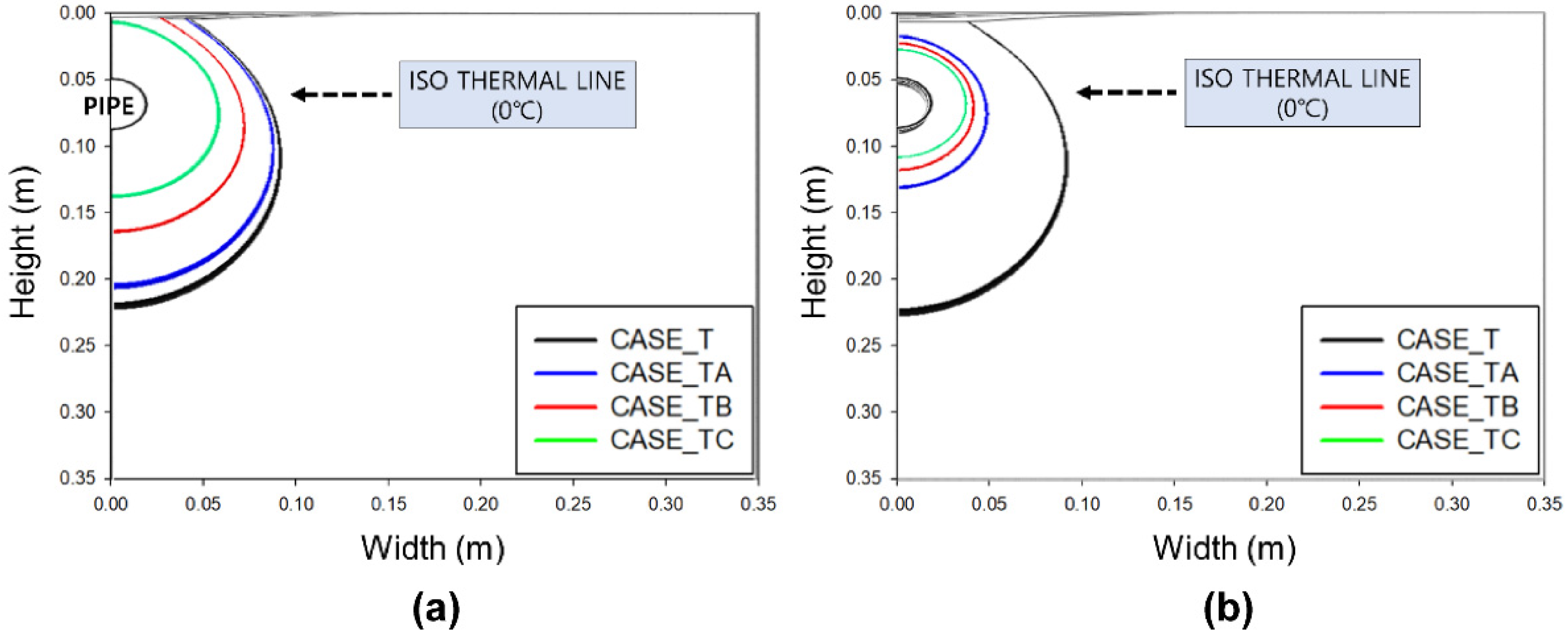
The thaw bulb shapes (y–z plane) with the maximum and minimum thaw-penetration depths are demonstrated in Figure 17. Notably, the shape of the thaw bulb features a large depth compared to its width direction, which is attributed to the effect of the boundary condition of the top surface and the thermosiphons.
The thaw-bulb size in all cases decreases as the number of thermosiphons increases. Notably, in CASE_TA, the difference in size between the maximum and minimum thaw bulbs is remarkably large compared with that of the other cases. However, the maximum thaw bulb of CASE_TA is not significantly distinct from that of CASE_T because the thermosiphons applied to CASE_TA are located at No. 7 in the x-direction and exert a limited effect on the soil adjacent to No. 1, which is located far from the thermosiphons, thereby resulting in the large size of the thaw bulb.
This tendency to form a thaw bulb induces a displacement tendency in the buried pipeline. Similar to the results of the frost-heave scenario, the trend of pipeline displacement indicates a small change as the number of thermosiphons increases.
Figure 18a graphically demonstrates the time-dependent results of CASE_T. Notably, the pipeline displacement converges toward the end phase of the thaw-bulb formation (680 h). Similarly, the convergence times of the cases using the same number of applied thermosiphons are identical to those corresponding to the thaw-bulb formation tendency. The convergence time is shortened as the number of applied thermosiphons is increased. The pipeline displacement results for all the cases are illustrated in Figure 18b. The final pipeline displacement decreases as the number of applied thermosiphons increases. For CASE_TA, CASE_TB, and CASE_TC, the pipeline displacements are reduced by 42.81, 70.15, and 82.36%, respectively, compared to that of CASE_H.
The axial stress demonstrates a decreasing tendency as the number of thermosiphons increases, similar to that observed in the frost-heave scenario. However, as the direction of the pipeline displacement is in the opposite direction, the top portion of the pipeline (P-7-0) verifiably receives negative stress due to axial compression, and the bottom portion of the pipeline (P-7-180) receives positive stress due to axial tension, as indicated in Figure 19.
The converged axial stresses for all cases decrease according to the number of thermosiphons, similar to the trend observed in the frost-heave scenario. Figure 19c shows the maximum axial stress measured at measurement points “P-7-0” and “P-7-180”. In the case of reduction rate, the axial stress of CASE_TA, CASE_TB, and CASE_TC were compared based on the axial stress of CASE_T. The axial stress (axial compression) measured at the measurement point “P-7-0” showed a 55.52% reduction rate in the case of CASE_TA and an 83.61% reduction rate in the case of CASE_TC. The axial stress (axial tension) measured at the measurement point “P-7-180” also showed a similar reduction rate trend and showed a reduction rate of 85.25% in the CASE_TC.

5. Conclusions

In this study, numerical analyses were performed to compare the behavior of the soil and a buried pipeline through frost heave and thaw settlement with thermosiphon application. For that, the frost-heave and thaw-settlement scenarios were established, and finite element analysis was conducted using the frost-heave model [23] and the thermosiphon model [20], which were applied via user subroutines in ABAQUS. The main numerical analysis results and conclusions of this study are as follows:
In the case of the frost-heave scenario, it was confirmed that as the number of thermosiphons increased, the displacement of soil and the pipeline and the axial stresses of the pipeline decreased. Compared to CASE_H, the maximum reduction rates of pipeline displacement in CASE_HC were 62.71%. Furthermore, the maximum reduction rate of the axial stress (tension) in CASE_HC was 63.75%; the maximum reduction rate of the axial stress (compression) was 61.92%. Similar to the frost-heave scenario, it was confirmed that the ground-stabilization performance increased as the number of thermosiphons increased in the thaw-settlement scenario. As the number of applied thermosiphons was increased, the pipeline displacement decreased accordingly. Compared to CASE_T, the maximum displacement reduction rate of CASE_TC was 82.36%. In addition, the maximum axial stress reduction rate was 83.61% (axial compression) and 85.25% (axial tension) for CASE_TC.
The results of this study verified that as the number of thermosiphons was increased, the frost-heave and thaw-settlement behaviors of pipelines and soil were effectively suppressed. Specifically, thermosiphons verifiably and significantly improved the ground-stabilization performance for these two behavioral conditions of the soil. However, in order to simulate the relationship between pipelines and thermosiphons used in the real environment, environmental conditions such as air temperature and multi-layered soil, and various installation variables such as the placement distance between the thermosiphons and the pipeline and the buried depth should be reflected, and these conditions and installation variables offer various avenues for future research directions.

Author Contributions

Conceptualization, D.-S.P.; Methodology, D.-S.P. and M.-B.S.; Software, D.-S.P., M.-B.S., and W.-J.P.; Formal analysis, D.-S.P., M.-B.S., and W.-J.P.; Validation, D.-S.P.; Writing—Original draft preparation: D.-S.P.; Investigation, M.-B.S. and W.-J.P.; Project administration, Y.-K.S.; Supervision, Y.-K.S.; Writing—Review and editing: Y.-K.S. All authors have read and agreed to the published version of the manuscript.

Funding

This work was supported by the National Research Foundation of Korea (NRF) through a grant funded by the Korea government (MSIT, No 2021R1F1A1051104).

Conflicts of Interest

The authors declare that they have no known competing financial interests or personal relationships that could have appeared to influence the work reported in this paper.

References

  1. Li, H.; Lai, Y.; Wang, L.; Yang, X.; Jiang, N.; Li, L.; Wang, C.; Yang, B. Review of the State of the Art: Interactions Between a Buried Pipeline and Frozen Soil. Cold Regions Sci. Technol. 2019, 157, 171–186. [Google Scholar] [CrossRef]
  2. Konrad, J.M.; Morgenstern, N.R. A Mechanistic Theory of Ice Lens Formation in Fine-Grained Soils. Canad. Geotech. J. 1980, 17, 473–486. [Google Scholar] [CrossRef]
  3. Lytton, R.L.; Pufahl, D.E.; Michalak, C.H.; Liang, H.S.; Dempsey, B.J. An Integrated Model of the Climatic Effects on Pavements; Federal Highway Administration Report No. FHWA-RD-90-033; Federal Highway Administration: Washington, DC, USA, 1993.
  4. O’Neill, K.; Miller, R.D. Numerical Solutions for a Rigid-Ice Model of Secondary Frost Heave; CRREL Report 82-13, U.S. Army Corps of Engineers; Cold Regions Research and Engineering Laboratory: Hanover, NH, USA, 1982. [Google Scholar]
  5. Sheng, D. Thermodynamics of Freezing Soils: Theory and Application. Doctoral Dissertation, Luleå University of Technology, Luleå, Sweden, 1994. 141 D. [Google Scholar]
  6. Hartikainen, J.; Mikkola, M. General Thermomechanical Model of Freezing Soil with Numerical Application. In Ground Freezing 97; Frost Action in Soils; Balkema: Rotterdam, The Netherlands, 1997; pp. 101–112. [Google Scholar]
  7. Michalowski, R.L. A Constitutive Model of Saturated Soils for Frost Heave Simulations. Cold Regions Sci. Technol. 1993, 22, 47–63. [Google Scholar] [CrossRef]
  8. Selvadurai, A.P.S.; Hu, J.; Konuk, I. Computational Modelling of Frost Heave Induced Soil–Pipeline Interaction II. Modelling of Experiments at the Caen Test Facility. Cold Regions Sci. Technol. 1999, 29, 229–257. [Google Scholar] [CrossRef]
  9. Dallimore, S.R. Observation and Predictions of Frost Heave around a Chilled Pipeline. Doctoral Dissertation, Carleton University, Ottawa, ON, Canada, 1985. [Google Scholar] [CrossRef]
  10. Ming, F.; Yu, Q.H.; Li, D.Q. Investigation of Embankment Deformation Mechanisms in Permafrost Regions. Transport. Geotech. 2018, 16, 21–28. [Google Scholar] [CrossRef]
  11. Peng, H.; Ma, W.; Mu, Y.H.; Jing, L. Impact of Permafrost Degradation on Embankment Deformation of Qinghai-Tibet Highway in Permafrost Regions. J. Central South Univ. 2015, 22, 1079–1086. [Google Scholar] [CrossRef]
  12. Park, D.S.; Shin, M.B.; Seo, Y.K. Frost Heave of Frost Susceptible Soil According to Performance of Thermo-syphon. J. Kor. Geotech. Soc. 2021, 37, 27–40. [Google Scholar] [CrossRef]
  13. Andersland, O.B.; Ladanyi, B. Frozen Ground Engineering, 2nd ed.; John Wiley & Sons, Inc.: Hoboken, NJ, USA, 2004. [Google Scholar]
  14. Alizadehdakhel, A.; Rahimi, M.; Alsairafi, A.A. CFD Modeling of Flow and Heat Transfer in a Thermosyphon. Int. Comm. Heat Mass Transf. 2010, 37, 312–318. [Google Scholar] [CrossRef]
  15. Fadhl, B.; Wrobel, L.C.; Jouhara, H. Numerical Modelling of the Temperature Distribution in Two-phase Closed Thermosyphon. Appl. Therm. Eng. 2013, 60, 122–131. [Google Scholar] [CrossRef] [Green Version]
  16. Jafari, D.; Filippeschi, S.; Franco, A.; Di Marco, P. Unsteady Experimental and Numerical Analysis of a Two-phase Closed Thermosyphon at Different Filling Ratio. Exp. Therm. Fluid Sci. 2017, 81, 164–174. [Google Scholar] [CrossRef]
  17. Abdalla, B.A.; Mei, H.; McKinnon, C.; Gaffard, V. Numerical Evaluation of Permafrost Thawing in Arctic Pipelines and Mitigation Strategies. In Proceedings of the Arctic Technology Conference, St. John, NL, Canada, 24–26 October 2016. [Google Scholar] [CrossRef]
  18. Abdalla, B.; Fan, C.; McKinnon, C.; Gaffard, V. Numerical Study of Thermosyphon Protection for Frost Heave. In Proceedings of the ASME 34th International Conference on Ocean, Offshore and Arctic Engineering (OMAE2015), St. John, NL, Canada, 31 May–5 June 2015. [Google Scholar] [CrossRef]
  19. Xu, J.; Eltaher, A.; Jukes, P. Three-dimensional FE Model for Pipeline in Permafrost with Thermosyphon Protection. In Proceedings of the Arctic Technology Conference, Houston, TX, USA, 7–10 February 2011. [Google Scholar] [CrossRef]
  20. Park, D.S.; Shin, M.B.; Seo, Y.K. Development of Numerical Analysis Model for the Calculation of Thermal Conductivity of Thermo-syphon. J. Kor. Geotech. Soc. 2021, 37, 5–15. [Google Scholar] [CrossRef]
  21. Jang, C.; Choi, C.; Lee, J.; Lee, C. Evaluation on Thermal Performance of Thermosyphon by Numerical Analysis. J. Kor. Geotech. Soc. 2014, 30, 57–66. [Google Scholar] [CrossRef]
  22. Lee, J.; Lee, C.; Jang, C.; Choi, C. Experimental and Numerical Investigation of the Performance of Vertical Thermosyphon for Frozen Ground Stabilization. J. Kor. Geosynth. Soc. 2014, 13, 45–56. [Google Scholar] [CrossRef]
  23. Zhang, Y.; Michalowski, R.L. Thermal-Hydro-Mechanical Analysis of Frost Heave and Thaw Settlement. J. Geotech. Geoenviron. Eng. 2015, 141, 04015027. [Google Scholar] [CrossRef]
  24. Huang, L.; Sheng, Y.; Wu, J.; Cao, W.; Peng, E.; Zhang, X. Experimental Study on Mechanical Interaction Between Buried Pipe and Soil During Freezing. Cold Regions Sci. Technol. 2020, 178, 103129. [Google Scholar] [CrossRef]
  25. Michalowski, R.L.; Zhu, M. Frost Heave Modeling Using Porosity Rate Function. Int. J. Num. Analyt. Methods in Geomech. 2006, 30, 703–722. [Google Scholar] [CrossRef] [Green Version]
  26. Dongqing, L.; Xing, H.; Feng, M.; Yu, Z. The Impact of Unfrozen Water Content on Ultrasonic Wave Velocity in Frozen Soils. Proc. Eng. 2016, 143, 1210–1217. [Google Scholar] [CrossRef]
  27. Tice, A.R.; Anderson, D.M.; Banin, A. The Prediction of Unfrozen Water Contents in Frozen Soils from Liquid Limit Determinations; CRREL Report 76-8, U.S. Army Corps of Engineers; Cold Regions Research and Engineering Laboratory: Hanover, NH, USA, 1976. [Google Scholar]
  28. Henry, K.S.; Zhu, M.; Michalowski, R.L. Evaluation of Three Frost Heave Models. In Proceedings of the Seventh International Conference on the Bearing Capacity of Roads, Railways and Airfields (BCRA’05), Trondheim, Norway, 25–27 June 2005. [Google Scholar]
  29. Henry, K.S. The Use of Geosynthetics to Mitigate Frost Heave in Soils. Ph.D. Dissertation, Civil Engineering Department, University of Washington, Seattle, WA, USA, 1998. [Google Scholar]
  30. Da Re, G.; Germaine, J.T.; Ladd, C.C. Triaxial Testing of Frozen Sand: Equipment and Example Results. J. Cold Regions Eng. 2003, 17, 90–118. [Google Scholar] [CrossRef]
  31. Zhao, X.D.; Zhou, G.Q.; Chen, G. Triaxial Compression Strength for Artificial Frozen Clay with Thermal Gradient. J. Central South Univ. 2013, 20, 218–225. [Google Scholar] [CrossRef]
  32. Ong, K.S.; Goh, G.; Tshai, K.H.; Chin, W.M. Thermal Resistance of a Thermosyphon Filled with R410A Operating at Low Evaporator Temperature. Appl. Therm. Eng. 2016, 106, 1345–1351. [Google Scholar] [CrossRef]
  33. Zhang, Y. Thermal-Hydro-Mechanical Model for Freezing and Thawing of Soils. Doctoral Dissertation, The University of Michigan, St. Ann Arbor, MI, USA, 2014. [Google Scholar]
  34. Fukuda, M.; Kim, H.S.; Kim, Y.C. Preliminary Results of Frost Heave Experiments using Standard Test Sample Provided by TC8. In Ground Freezing 97; Frost Action in Soils; Balkema: Rotterdam, The Netherlands, 1997; pp. 25–30. [Google Scholar]
  35. Kosky, P.; Balmer, R.T.; Keat, W.D.; Wise, G. Exploring Engineering, 3rd ed.; Academic Press: Waltham, MA, USA, 2013. [Google Scholar] [CrossRef]
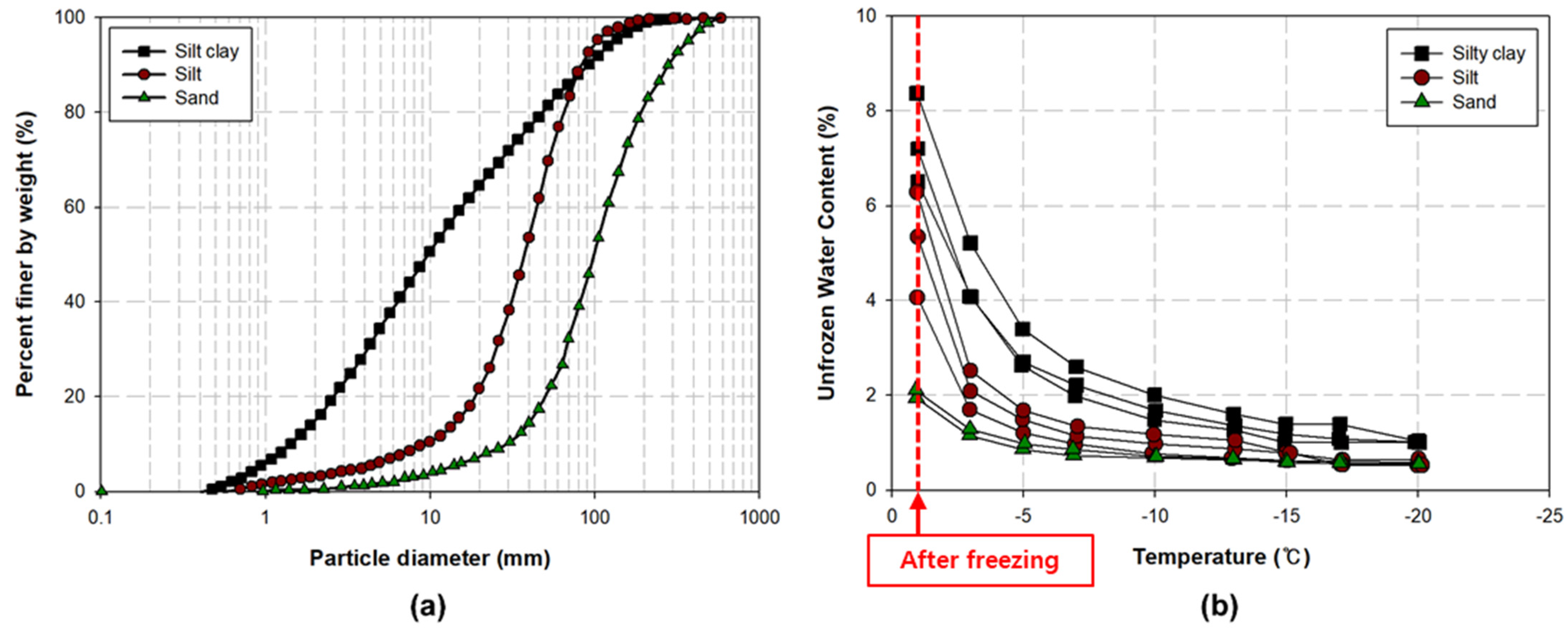
Figure 1. Comparison of different soils characteristics: (a) grain size of different soils; (b) unfrozen water contents of different soils.
Applsci 13 01948 g001
Figure 2. Accuracy of frost-heave models.
Applsci 13 01948 g002
Figure 3. (a) Tendency of porosity rate for different soils; (b) frost-heave amount by n ˙ m .
Applsci 13 01948 g003
Figure 4. (a) Normal compression lines (NCLs) and unloading–reloading lines (URLs) for unfrozen soil and frozen soil; (b) NCL and URL for unfrozen soil and frozen soil in semilog space; (c) yield surface and critical state line (CSL) for unfrozen soil and frozen soil.
Applsci 13 01948 g004
Figure 5. Cross-sectional view of a thermosiphon: (a) schematic and (b) concept.
Applsci 13 01948 g005
Figure 6. User subroutines for thermomechanical (TM) model.
Applsci 13 01948 g006
Figure 7. Geometry of two types of scenario models: (a) frost heave and (b) thaw settlement.
Applsci 13 01948 g007
Figure 8. Arrangement of thermosiphons in different scenarios and cases: (a) frost heave and (b) thaw settlement.
Applsci 13 01948 g008
Figure 9. Measurement points of soil and pipeline: (a) x-direction number and (b) y–z plane alphabet and angle.
Applsci 13 01948 g009
Figure 10. Temperature variations at measurement points with respect to time: (a) CASE_H, (b) CASE_HA, (c) CASE_HB, and (d) CASE_HC.
Applsci 13 01948 g010
Figure 11. Comparison of results corresponding to points “S-1-B” and “S-6-B”: (a) unfrozen water content and (b) pore ice ratio.
Applsci 13 01948 g011
Figure 12. Frost heave along the width at different times: (a) CASE_H (No. 1), (b) CASE_H (No. 6), (c) CASE_HA (No. 1), and (d) CASE_HA (No. 6).
Applsci 13 01948 g012
Figure 13. Pipeline displacement along the length at different times: (a) CASE_H and (b) CASE_HC.
Applsci 13 01948 g013
Figure 14. Axial stress along the length for all cases: (a) top line of pipeline and (b) bottom line of pipeline.
Applsci 13 01948 g014
Figure 15. Results obtained at measurement point “S-1-I” for all cases: (a) temperature, (b) unfrozen water content, and (c) pore ice ratio.
Applsci 13 01948 g015
Figure 16. Time progression of thaw-penetration depth at x–z symmetry plane: (a) CASE_T, (b) CASE_TA, (c) CASE_TB, and (d) CASE_TC.
Applsci 13 01948 g016
Figure 17. Maximum and minimum thaw bulbs for all cases in the x-direction at: (a) No. 1 and (b) No. 7.
Applsci 13 01948 g017
Figure 18. Displacement of pipeline: (a) results of CASE_T at different times and (b) results for all cases.
Applsci 13 01948 g018
Figure 19. Axial stress of pipeline: (a) CASE_T (top side), (b) CASE_T (bottom side), and (c) results for all cases.
Applsci 13 01948 g019
Table 1. Classification of all cases.
ScenarioCase NameNumber of
Thermosiphons
(symmetry)
Radius
of
Pipeline
(m)
Thickness
of
Pipeline
(m)
Thickness
of
Insulation
(m)
Buried Depth
of
Pipeline
(m)
Initial Temp.
(°C)
Temp. (°C)
and
h* (W/m2K)
of
Top Surface
Temp. (°C)
and
h (W/m2K)
of
Pipeline
Frost HeaveCASE_H-0.0190.0008-0.0193−5
and
5
-
CASE_HA2 pair
CASE_HB 2   pair × 2
CASE_HC 2   pair × 3
Thaw SettlementCASE_T-0.00320.0666−15−15
and
5
60 and 55
CASE_TA2 pair
CASE_TB 2   pair × 2
CASE_TC 2   pair × 3
Table 2. Material properties and parameters of soil mixture.
Thermal Properties of Soil Mixture
Soil Skeleton Water SkeletonIce Skeleton
Density   ( kg / m 3 )26201000917
Mass   heat   capacity   ( J / kg   K )90041802000
Thermal   conductivity   ( W / m   K )1.950.562.24
Parameters for unfrozen water content of soil mixture
ω ¯ ,   ω * 0.285, 0.058
α   ( ° C 1 )0.16
T 0   ( ° C )0
Parameters for porosity rate function model
n ˙ m   ( s 1 ) 0.33 ·   10 5
g T   ( ° C / m )100
T m   ( ° C )−0.82
T 0   ( ° C )0
Parameters for elastic–plastic constitutive model
Poisson’s ratio0.3
λ ,   κ ,   M ,   β 0.35, 0.07, 0.7, 0.18
α 1 ,   α 2 0.2, 0.4
p 0 ,   p r   ( kPa )80, 10
Disclaimer/Publisher’s Note: The statements, opinions and data contained in all publications are solely those of the individual author(s) and contributor(s) and not of MDPI and/or the editor(s). MDPI and/or the editor(s) disclaim responsibility for any injury to people or property resulting from any ideas, methods, instructions or products referred to in the content.