1. Introduction
Assembly is considered a key step of the entire fabrication process, on the one hand because it is the costliest phase, accounting for 30-40% of total manufacturing costs on average [
1,
2,
3]; on the other, because the efficiency and accuracy in the execution of assembly tasks may affect the final quality of the product, in addition to total production time and cost. Unlike other industrial processes such as cutting, milling and forming, which have been highly automated in the years, assembly is in large part still conducted manually today [
4].
Assembly sequences are frequently lengthy and complex, involving many components to be assembled in a particular order and often dealing with fine adjustment operations to ensure an acceptable result that meets project requirements. These factors, together with others related to the assembly system (e.g., workplaces with high noise and poor ergonomics), the product (e.g., many or similar components) and the worker (e.g., skills, training level, and experience) can affect the process and lead to human errors [
5]. Assembly errors must be avoided, as they could result in production wastes and defects, with increased time and additional costs to be faced. To this purpose, different methods are used in industry as support and guidance to the human operator. Among others, are training sessions, which can be time-consuming and expensive, especially if realized through the consultation of paper manuals and reference tables that could lead to time inefficiencies and distractions. Moreover, paper-based assembly instructions have become more difficult to provide and locate inside organizations, due to increasing product variants derived from growing demand for manufacturing flexibility [
6]. Further, using written instructions, the worker needs to switch the attention between the task being performed and the instructions given, having to remember the information read, with increased cognitive load [
7].
Augmented Reality (AR) technology has made great strides over the last decades and the development of AR solutions to support manual assembly has experienced a steady increase [
8]. Interactive and real-time assembly instructions can be visualized by the operator for guidance and training, also giving the opportunity to receive feedback on the process, thanks to the capability of AR to overlay virtual information on the real environment [
9]. According to recent studies, the use of AR in assembly tasks can reduce execution times and errors, enhancing the correct interpretation of instructions [
10], and solving problems related to paper-based information, such as lack of flexibility [
7]. The operator does not continuously switch the attention between the information and the assembly, thus enhancing ergonomics [
11]. Furthermore, new workers can be trained by AR systems, without sacrificing the time of other employees to train them.
Although AR is widely used for this kind of applications, other tools can be implemented among the Extended Reality (XR) ones, which refers to technology-mediated experiences enabled via a wide spectrum of hardware and software, including sensory interfaces, applications, and infrastructures. These immersive technologies are ever more used to assist workers and provide support in enhancing industrial processes such as assembly [
12]. In particular, Mixed Reality (MR) is showing similar trends to AR. MR is a combination of a virtual world and the real world, which are merged to construct an enriched environment that the user is allowed to interact with [
13]. In industry, the use of MR, mostly implemented by means of eye-wear devices [
13], has proven that new workers can be trained more effectively, efficiently, and safely, if compared to traditional methods. Instructions given to workers by animations, text, and audio [
14] enhance their skills and knowledge, improving information processing during maintenance operations and increasing recall in short and long-term memory [
15]. Studies have demonstrated that using MR guidance instead of traditional paper instructions can decrease workers’ errors, misinterpretations, or overlooking of information [
9]. Quantitative and qualitative research show that MR-based assembly guidance records lower task execution times, higher accuracy and usability, and reduction of cognitive load compared to other training formats [
16].
3. Materials and Methods
The MR application developed in this work aims to assist the users during the assembly of a product with a simple temple structure composed of blocks and labels, and is designed to interactively support the users throughout the assembly steps, from the initial setup displayed in
Figure 1 to the final product shown in
Figure 2.
The following subsections will explain the software and equipment used for the development, the programming methods, the application development workflow, and the experiment design for the validation of the app. The work presented here, with the experiment performed on the simple product, is a necessary first step in the development and realization of such a tool, and in improvement of the basic idea behind tool conception to a more consistent proof of concept of the application (TRL 4-6). In the future, this application could be expanded and further developed using a real-time product and a real workshop environment.
3.1. Software and Equipment
MR system software and equipment utilized in this work are chosen according to that which is currently state of the art and to respect the following criteria concerning application requirement: ease-of-access, ease-of-use, and practicality for long-term use.
As for software, the MR system is designed by using Unity Engine and Vuforia Engine Software Development Kit (SDK). They are widely used in the development of MR system. Vuforia, in particular, was chosen given its broad range of recognition and tracking capabilities. Among the different target recognition techniques supported by Vuforia, Model Targets (MT), and Image Targets (IT) are the most suitable for the MR system developed in this work.
The MT is an object-tracking method that allows for real-world recognition and tracking of objects based on their shapes and features. It can be applied using a 3D model of the object, which is then converted into a Vuforia Engine model using the MT Generator (MTG) tool and stored in a database collecting all the design features that allow it to detect the objects in the real-world scene. An Advanced Model Target Database (AMTD) can be produced by training a database with one or more Model Targets, each containing advanced guide views ranging up to 360° in all rotations. Advanced guide views allow for recognizing and tracking objects from different angles in a defined range. As the objects modeled in the system move in the environment, the positions of the objects need to be anticipated or tracked. For this reason, each object needs its own coordinate system (CS) to be anticipated or tracked in the MR system.
The IT is an image recognition technique that allows the detection and tracking of images by comparing the features extracted from camera images with known targets stored in a database. Once detected, Vuforia Engine augments data of the target’s features in the real-world scene that can be used to interact with the users.
As for equipment, the display device chosen was the HoloLens 2, i.e., perspective holographic glasses that allow the users to interact with the augmented- and real-world environment. The choice fell on the HoloLens 2 device because of its ability to map the real-world environment with built-in cameras and sensors and its compatibility with both software Unity and Vuforia engine selected for MR applications.
The physical tools that the users needed to use while performing the experiment comprised three battery-powered screwdrivers with heads fitting the screw sizes (two for assembling the block components, one for assembling the label screws). No other equipment was needed to perform the simple assembly operations, and nothing more was given to the users to avoid confusion.
3.2. Programming Method and Logic
Each object in Unity engine is called a GameObject and is controlled by scripts in the developed MR application that were written in C#. These scripts were mainly used to manage the behavior of the objects and to define their actions, such as control object movements, audio instructions, blink a color effect, the UI panels, and so on. The GameObjects have a hierarchical structure of so-called ”manager scripts”. The manager scripts cover the logic of a specific application feature such as audio, graphics, data collection, and so on.
The scripts were written following a structured method for programming that follows a state-step and transition logic: the states/steps are the classes scripts which have specific outputs; the transitions set the logical conditions that, if satisfied, allow to move on to the next state/step. The developed MR application uses recognition-driven transitions to drive the application’s logic. The transitions are thus based on the user’s action in relation to the assembly process.
3.3. Application Development Workflow
The application development focused on providing users with a comprehensive and comfortable assembly experience. The development is divided into two steps, followed by an experimental phase aiming at testing and validating the developed application.
The first step of the application development was to create simple graphic guidance for users to assemble the product. The main elements of the graphic were 3D augmentation of the corresponding assembly parts or the working assembly from the previous step in the real space. The graphic guidance was programmed using the state/step, and transition logic explained in
Section 3.2. The steps consist of component selection, placement, and assembly validation and correction. The realized MR system is described and discussed in detail in
Section 4.
The second step was to design and create audio guidance, UI-panels, and user-action validation features to improve the application’s useability. The audio guidance gives verbal instructions, whereas UI-panels complement the audio guidance with written instructions. The validations feature allows the system to test whether the users correctly picked and assembled the parts. The application moves to the next state/step if the validation is successful.
Once steps one and two were completed, experiments were conducted to validate the realized MR system by testing the application performance and the user experience.
4. Application
The application guides the user through the assembly of the simple product of
Figure 1, with the aid of visual graphic animations, audio instructions, and over imposed UI panels.
Table 1 lists the operations that are needed to complete the assembly, using the spare parts in the component box of
Figure 3.
The workflow of the application is described in
Figure 4 and highlights a complete cycle of the MR experience. Furthermore, each step consists of three or more sub-steps: component selection, component placement, assembly validation, and additional correction sub-step, when relevant.
4.1. Development
The logic of the application is driven by two absolute CSs, one for the assembly setup, and the other for the component box. Both setups have complex non-symmetric features, they are not exceedingly reflective of light, and have minimal to no movement, which lends them for easy recognition with MR devices. Creating the CSs is done only once at the beginning of the MR experience, because the position, rotation, and state of all other components could be inferred from the position of the initial CSs. After calibration, the prepared workstation appears as in
Figure 5.
Then, the iterative steps can be performed for each component, starting from the first component selection. When the selected part has been validated as correct, the application jumps to the next step: placement. When the part is positioned, assembly validation starts. When it is recognized as correct, the app goes again to the component selection step (for the next component). If the validation is not completed, the app goes into the correction sub-step, until the component is correctly set on the assembly.
For each component selection step, the user selects one part from the component box to assemble next, and the app validates the selection of the correct part from the assembly sequence, informing the operator of any possible error (see
Figure 6).
Then, the component graphic guides the user to assemble the component correctly onto the product (see
Figure 7a,b): an animation shows the correct part moving from the starting position in the component box to the final assembly position, and with the right orientation.
At every step, a validation guidance graphic (VGG) is displayed to verify the correct positioning of the components. The VGG will be thoroughly discussed in
Section 4.4. After correct validation through the VGG, the app proceeds with the next step in the list, performing the same operations just described for each part. If the validation step is not completed, the correction sub-step starts, offering a new animation with audio to correct the position or orientation of the component.
The application features two types of graphics for visual guidance: static graphics guide the user to select the correct component from the component box at each step and warn them of wrong component selection; moving graphics guide users to the correct positioning of components onto the assembly. The static component graphics are green when the correct component is selected, and red when it is incorrect. Such graphics appear both in relation to the component box and the assembly setup.
The “Audio Manager” controls the audio logic according to the ongoing step of the application. Thanks to a text-to-speech program, the app provides voiced instructions. Two types of audio clips play automatically in a sequence at the start of each step: clips that play only once, and loop audio clips that keep repeating until the step is completed. Audio clips that contain crucial information for completing the assembly tasks are played in a loop. The application also features a distinct sound that is played when actions are performed correctly, and a distinct sound for when the application recognizes incorrect actions. The audio serves to enhance the user’s experience and immersion with the application, as well as provide additional information difficult to give through the UI (e.g., screwdriver selection, placing label text facing up).
The application also includes UI-panels to display written information on the assembly procedure for each step. The “UI-Panel Manager” controls the panels, ensuring that only relevant information is visible. The UI-panels have buttons to allow the transition to the following step. The manual transition option is included in case assembly validation logic fails. The panels initially follow the device camera, but when the assembly position is calibrated the UI-panels position changes to a fixed one relative to the assembly CS.
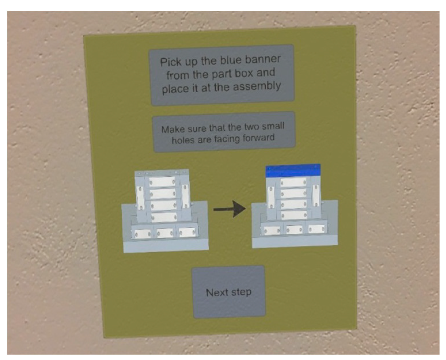
Figure 8 shows an example of the UI-panel.
4.2. Component Selection Validation
Given the simple features of the empty pockets in the component box, and the slow and uncomfortable procedure for validation due to the hands of the user interfering with the visuals of the components, the internal hand-tracking capabilities of the HoloLens 2 were used to solve the issue for component selection. The HoloLens 2 tracks the hand movements of the user and estimates the position of hand and finger joints. The application tracks index finger positions using MRTK, a Microsoft-driven project providing components and features for cross-platform MR application development in Unity.
Figure 9 demonstrates the tracking of the index finger for component selection.
To validate which component has been selected, the estimated index finger position is compared to the position of component GameObjects in the component box, each of which has a bounding box. According to how people are expected to place the index finger when picking up a component, a counter computes the number of times the index finger intersects the bounding box. To proceed with validation, the app estimates that the selected component is the one with the highest count. If then the “Component Selection Manager” validates the correct component, it tells the “Master Step Manager” to go to the placement sub-step; if an incorrect component selection is detected, graphics and audio inform the user of the incorrect selection.
4.3. Assembly Validation
The application visual validation at the end of each step is based on the recognition capability of Vuforia Engine’s AMTD. The Vuforia MTG can train a database of Model Targets in relation to one another, to distinguish between their appearances. For this application, an AMTD was trained for the validation phase of each step, including the following Model Targets:
Assembly setup before placing the components of a step;
Assembly setup with the correct positioning of components in a step;
Assembly setup with the incorrect positioning of components in any step (if relevant).
The Model Targets in the assembly are similar in size and number and type of features (surfaces and counter bore holes), therefore distinguishing amongst them on appearance alone—as is the behavior when training with Vuforia MTG—becomes difficult. To solve the problem, the guide view of the Model Targets was set to focus on the features with the major differences, though also limiting the effectiveness to specific camera angles and distances. The solution is the Validation Guidance Graphic, discussed in
Section 4.4.
Though the selected guide views for recognition include the specific features of the assembly models, the model recognition does not have a 100% success rate. Shared features of the Model Targets sometimes are misjudged by the trained algorithm and an incorrect Model Target is recognized. Vuforia recommends models that are trained in the MTG to be complex, because it is then easier for the algorithm to recognize them. Although the models in this application are fairly complex, zoomed and narrow guide views might mislead the Model Target algorithm to include features from other objects in the environment and lead it to false positive recognition. So, a more robust validation routine for a higher validation success rate was adopted: for a Model Target to be validated, the algorithm needs to recognize it three times from different angles. After each Model Target recognition, the user must slightly move the headset in any direction for another recognition to occur. Only with three consequent correct recognition of the same model the validation step is passed, otherwise the validation process starts over.
Figure 10 shows the graphic displayed in the application, informing the user of the validation progress.
4.4. Validation Guidance Graphic
A Validation Guidance Graphic (VGG) is displayed next to the setup to inform the user of what HMD positions are acceptable for validation. If the component is incorrectly placed onto the assembly, the application transitions to a correction step, where animations and audio will guide the user to correct the positioning.
The MTG trains the AMTD to distinguish between different Model Targets according to the guide views specified for each Model Target. The application accepts validation of components only with suitable camera positions in relation to the assembly setup CS. Distance, height, and angle of the camera are important factors for the validation; therefore, a calibration system was developed to allow the user to take position at a suitable height, angle, and distance for each assembly validation. The validation guidance graphic (VGG) as it appears in the headset view is shown in
Figure 11.
The GameObject should be placed accordingly within the acceptance area (in green) for each validation step. A text indicates users to reposition if they need to. The VGG is placed next to the assembly setup at a visible position, but such that does not hinder the visuals on the assembly itself.
4.5. Image Recognition and Tracking
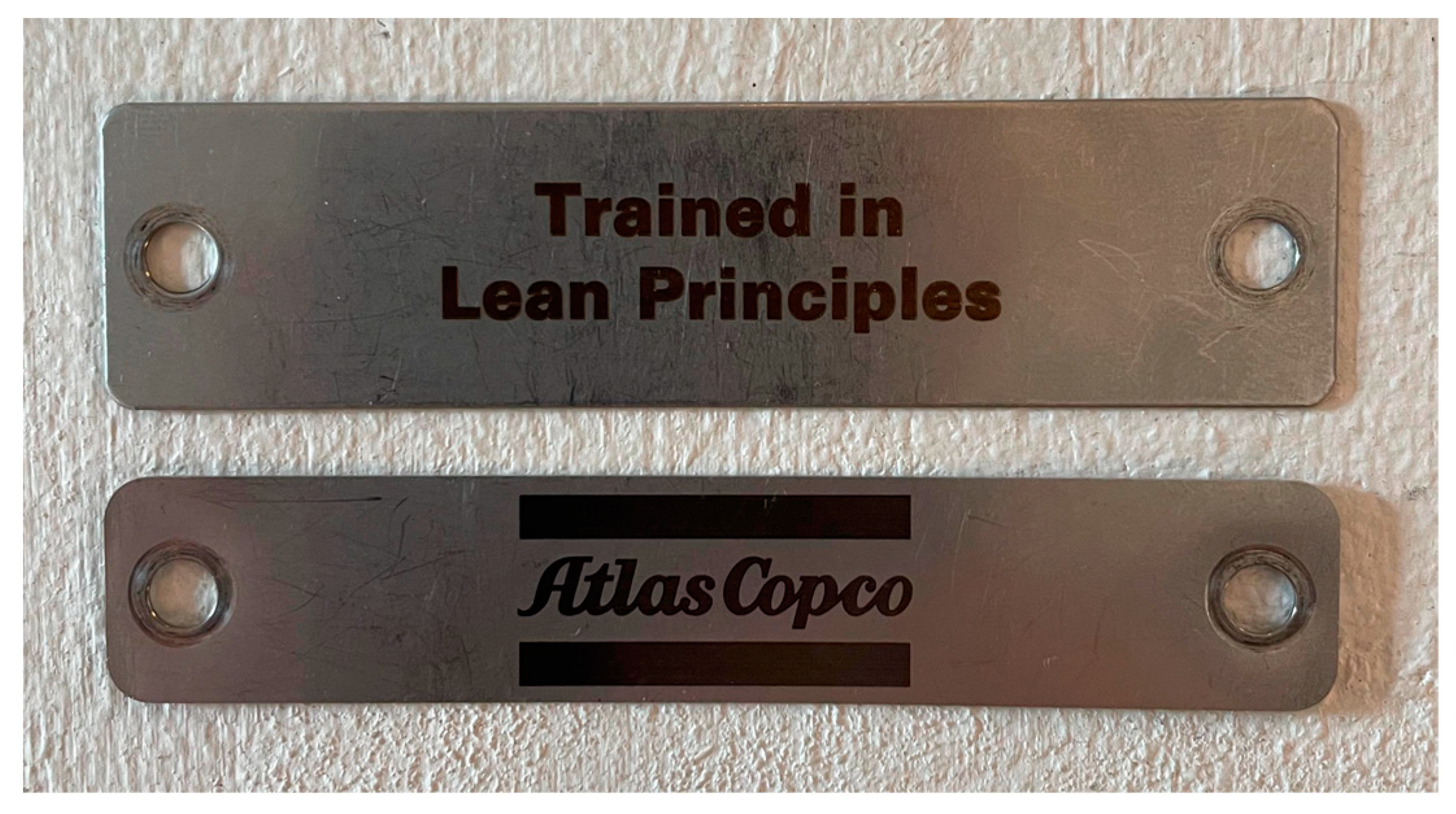
During steps 6 and 7 of the assembly procedure, the user needs to fasten two labels on the product (see
Figure 12). These labels cannot be treated as previous objects for validation purposes because they have text and images. So, Vuforia’s image tracking capabilities become useful for solving the issue, since Image Targets have no limitations in the number of objects that are recognizable at the same time. Object recognition of the assembly was thus combined with image recognition of the label to create a robust validation procedure.
This validation procedure excludes the correction of placement for components with text/image facing down. Only loop audio guidance saying to turn the label upside-down is offered to the user, and the Model Target validation does not start until the label text/image is recognized.
5. Results
In the following section, the experimental design and the test methodologies that have been followed to validate the usability of the app are presented. Then, the results for three specific tests on the validation procedure are shown, and the result of the performed experiments with the MR application as well (including component placement validation results, and time measurements for completion of the application steps). Last, the answers to the questionnaire provided by the participants to the experiments are listed and evaluated.
5.1. Experiment Design and Test Method
The experimental phase primarily intends to validate the developed MR-based support on assembly tasks by testing the users’ performance and experience.
The experiment took place at The Royal Institute of Technology (KTH) in the Lean assembly laboratory facility and involved ten participants aged between 23 and 26. The participants were recruited from different engineering master programs at KTH. All selected participants were inexperienced operators and did have previous experience using a MR application with HoloLens.
The experiment was divided into two parts: (a) a subject trial performed to collect quantitative measures, and (b) a post-experiment questionnaire to gather qualitative measures on the user experience.
In the first phase, the equipment was prepared, and each subject was asked to test it to become familiar with its features. The experimental procedure consisted of the participants completing the product assembly one time using the MR system. While completing the assembly, time measurements for each step, the number of mistakes made by the participants (i.e., incorrect placements and selections of components) and the success rate of the component selection validation algorithm were calculated by dedicated scripts and gathered in a dedicated database for analysis. In this phase, it was planned to collect the same data also from inexperienced subjects performing the operations with paper instructions guidance, but due to a lack of time and resources, the plan was re-scheduled for future experiments, as is better explained in
Section 7.1.
The collected inexperienced subjects’ performance was then compared with pre-defined benchmarks. The definition of the benchmark was performed in a separate session in which an expert operator executed the assembly procedure 10 times. The time to complete each assembly was recorded with and without the guidance of the MR application. The number of errors the expert made, and validation results for the assessment of components placed correctly, incorrectly, or not placed at all were recorded only by using the MR system.
In the second phase, the participants were asked to fill out the post-experiment questionnaire about their subjective perception of the MR system experience. The collected inexperienced subject perceptions were then compared with predefined benchmarks, and any feedback and suggestions were used to improve the application and validate the MR system’s user-experience.
5.2. Validation Tests
First, a test for the accuracy of the positioning validation procedure was performed: components were selected in order from the component box and accurately positioned in the correct position, to check whether the app showed false negative validations. Each step was performed 10 times. The accuracy of the application validation system was 100%, with no false negatives.
Then, the same test was performed to evaluate false positives, by intentionally placing a component incorrectly and trying the validation system, for the following steps: the banner and the roof were placed reversed (step 1 and 3, respectively), the “Atlas Copco” label was fastened on the roof instead of the banner part (step 6a), then both labels were placed upside down (step 6b and step 7). The application was only able to validate the banner as incorrectly placed in 50% of cases. It obtained an 80% success rate of validating that the roof had been placed incorrectly, and a 100% success rate of validating when the labels were placed incorrectly, for all steps.
A third validation test was performed to evaluate the application accuracy when no component was placed on the assembly, but the validation started, nonetheless. If no validation occurs within a minute, the correct behavior should be reporting that it is not possible to validate. This test was performed for all seven steps, and steps 6 and 7 for both Model and Image Targets. Step 4 had the worst result, with 0% success rate, meaning that the roof screws were validated as “in place”, when they were not. In steps 6 and 7, incorrect Model Target validations occurred in 80% of cases and 100% of cases, respectively, but no incorrect Image Target Validations occurred.
Table 2 shows the complete results for this test.
5.3. Component Selection Validation
Component selection validation accuracy for both experienced and inexperienced subjects was measured, and the results are hereby presented. Results include whether subjects selected the correct component or not, and then how the application validated the selection (correct/incorrect selection).
Figure 13 shows the results for the component selection validation. All participants selected the correct component at every repetition. For the expert user, the application was able to validate that the correct component had been selected 79 out of 80 times. The accuracy for the inexperienced subjects was lower: the application validated correct component selection 56 times, 4 times it mistakenly interpreted as the incorrect component had been selected, and 20 times it was not able to validate the component selection (for various reasons including bad positioning of the camera, bad lighting, and so on).
5.4. Component Placement Validation
Component placement validation accuracy measures how well the subjects understood how to place the components. The correct or incorrect positioning of one component was registered, along with the result of the validation by the application, to check false negatives and false positives. Both measures were collected for the expert operator and for the novice user. The expert achieved a 100% success rate, placing all the components correctly. The application always validated it correctly. The inexperienced user placed the components correctly 90% of the time (72 correct placement out of 80 attempts). The application validated it correctly 71 times (98.6%); however, one time it was not able to validate at all, so the participant skipped the validation step through the UI panel. Incorrectly placed components occurred eight times (10%), seven of which were correctly recognized by the app (87.5%); only once the app did not perform any validation, and the step was skipped. See
Figure 14 for the complete results.
Amongst all cases in
Section 5.2 and
Section 5.3, both for experienced and inexperienced users, the accuracy of the application validation was very high: excluding the already mentioned cases where no validation occurred, the accuracy of the validation process was at 100% in three cases, and 93.3% in the case of component selection validation for inexperienced users.
5.5. Time Measurements
Time measurements were collected for each step and sub-step. First, from an experienced user doing the assembly procedure 10 times without any guidance. The same user then used the MR application for guidance, completing the assembly procedure 10 times. These first two steps were planned to have a reference point to compare with the time registered for the application. Being this a simple product with easy to perform actions, we expected the times for assembling by the experienced user to be low, whereas the times collected when using MR, we expected to be higher, as they include the instructions and animations within the app. Lastly, 10 inexperienced subjects completed the assembly procedure using the MR application one time each. The average times for each assembly step can be seen in
Figure 15. The inexperienced users took a significantly longer time to complete each step compared to the experienced user, with or without MR guidance.
Figure 16 shows the average total time from both the experienced user and inexperienced users when using the MR application. The total time is split into component selection time, placement time, validation time, and corrections time. Components placement took the longest time for all users. This represents the time frame spanning from completing component selection to the start of the validation. For the experienced user no correction time is available since they committed no placement errors and the application always validated correctly.
5.6. Subjective Feedback
The participants answered a questionnaire regarding their experience using the MR application. The questionnaire focuses on the different elements designed for the application. The main goal was to get feedback on the application’s performance and the respondents’ perception and to collect suggestions for improvements. The answers are presented in the following paragraphs.
The MR application was considered as positive guidance for the assembly process as paper-based instructions, as 40% of the answers reported that MR was a better experience than following paper instructions, whereas 40% thought that paper-based were better (
Figure 17). However, the MR system gave a better feeling in the accuracy of the assembly process: 40% of the participants felt more confident in the operation they were performing, whereas only 30% of participants felt more confident using paper instructions (
Figure 18).
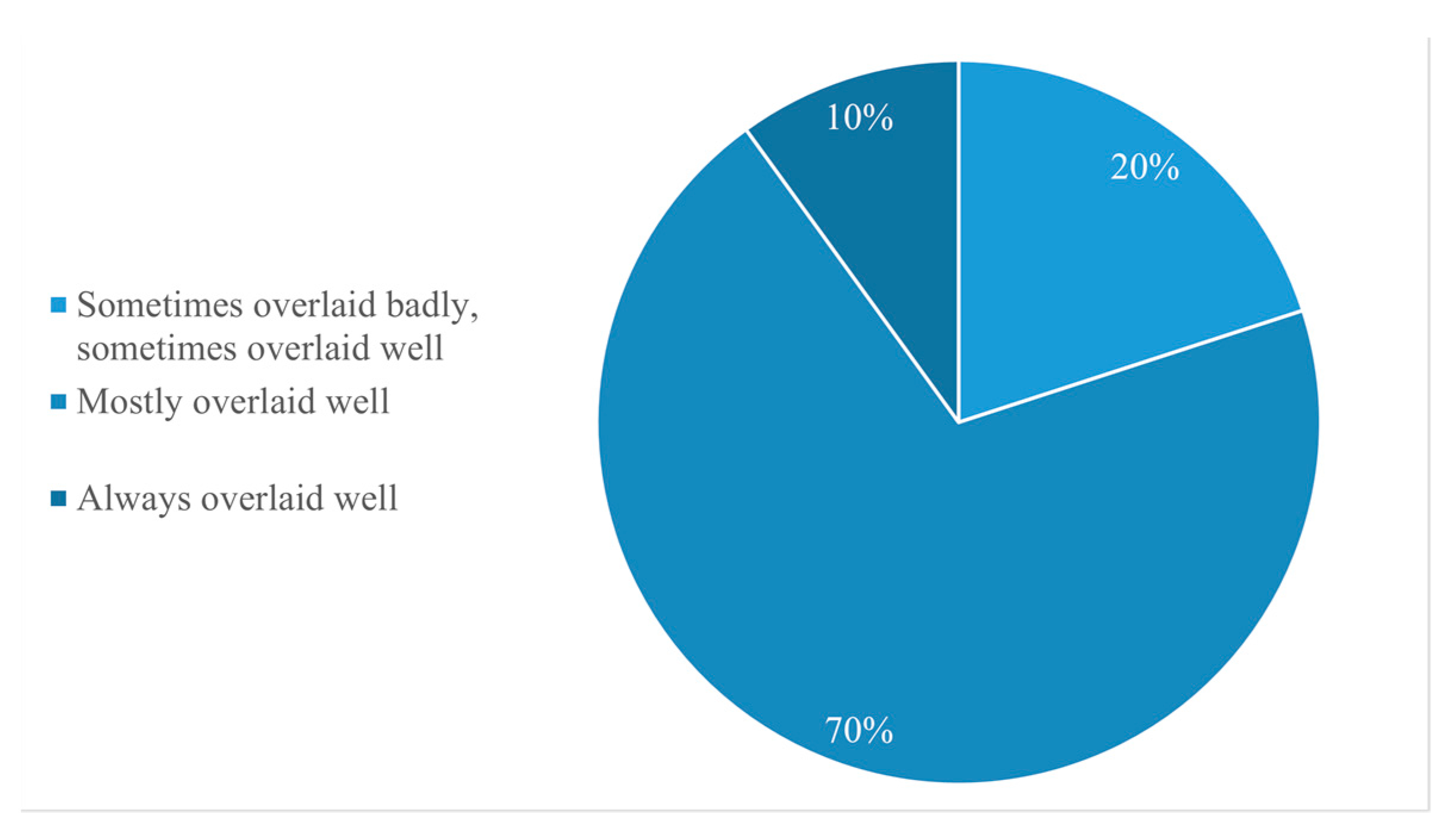
Most participants (70%) felt that the graphics overlay over the real-world objects was well-designed (
Figure 19). However, the application graphics often interfered when performing certain operations (
Figure 20), e.g., sometimes two pieces of graphics occluded each other or blocked real-world components, making it difficult to see where to place some pieces. This issue was mainly perceived during steps 6 and 7, while placing the label screws, as the graphics here occluded the screw holes.
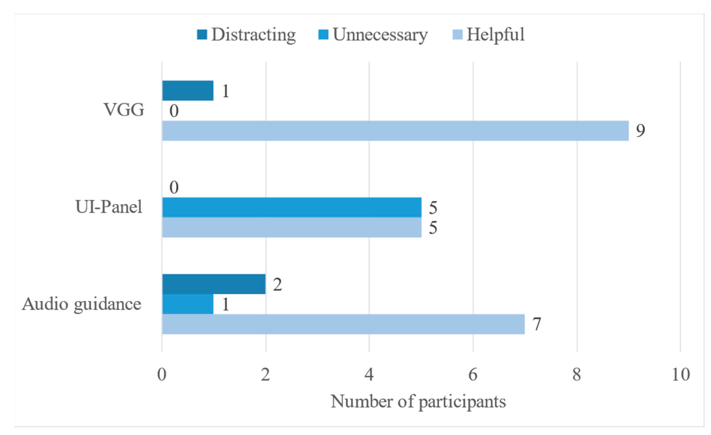
The subjects found the audio guidance and the VGG helpful in most cases. In addition, they found the UI-panel sometimes beneficial, but 50% of the subjects reported it being unnecessary, e.g., some of the participants forgot to utilize it, preferring graphic- and audio guidance (
Figure 21).
The MR application provided clear guidance to the operators regarding what component to select for the assembly step (
Figure 22). Moreover, in 90% of the cases, the MR application provided clear instructions on what part to pick compared to paper instructions (
Figure 23). Consequently, the participants always (40%) or mostly (50%) understood where and how to place the components in the assembly (
Figure 24).
As for the assembly validation process, subjects often had trouble validating the assembly because of the non-optimal posture: the assembly feature was positioned lower than the eye line, which requires a non-ergonomic posture for validation. Consequently, 60% of the participants thought the validation procedure was either uncomfortable or very uncomfortable (
Figure 25).
6. Discussion
The presented work includes the development of a fully functional MR application for part of the assembly of a simple product, and an exploration of the feasibility and technological readiness for a standardized method to produce realistic, helpful, augmented graphics in a real, dynamic environment.
The application goal was to realize effective, efficient, and user-friendly MR system methods for assembly training purposes. This work also featured the LML case study for applying the proposed MR method to a specific assembly scenario, though conclusions about the applicability of such method to different scenarios are discussed.
During the MR application experiments in the lab, data were acquired and have been already presented in
Section 5, providing descriptive results regarding building MR applications for industrial assembly. Further, users of the application participated in a questionnaire, designed to acquire their perception of the MR guidance system. The results show a strong proof of concept for many aspects of the MR system, while revealing underlying limitations of both the application features and the methods used.
6.1. Assembly Validation Accuracy
The validation accuracy results show the application effectiveness in validating correctly placed components, whereas it was not as effective for incorrectly placed components. The skewness towards false positive recognition depends on the low number of features in the model targets. Validation results would be more accurate if models imported in Vuforia contained a higher number of complex features, making it easier for the Model Recognition to decide whether a part has been placed incorrectly. In the case of both the banner and the roof, for example, the only difference when they are placed backwards is the visibility of the holes for the label screws, which is a small feature and, in conditions of imperfect lighting, leads to a false positive recognition.
Model Target validation step 4 (roof screws) showed that the app tried validation even when the component had not been placed, because of the minimal optical variation between the AMTD guide views with or without the roof screws: whereas the guide views for steps 1, 2, 3, and 5 presented substantial optical differences, the roof screws are mostly occluded by the screw-holes when place. Poor results in steps 6 and 7 were due to the numerous common features in the guide views that allows to validate the model only based on common features—which results in an incorrect validation process. In this case, the validation process can be improved by reducing the number of common features, and further restricting the guide view angles (which would in turn reduce comfort and speed of the application).
Nevertheless, during these last two steps, the Image Target validation that used the combined position and rotation of the tracked image in relation to the assembly model, achieved correct non-validation 100% of the time. Even though the Model Target validation failed most of the time for those steps, it did produce a perfect overall evaluation, because it needed to be evaluated concurrently with Image Targets.
The validation accuracy can potentially be improved, providing different guide views in the MTG, but at the same time, the process of creating Model Targets currently presents an underlying limiting issue when validating assembly processes: the black-box functionality of the object recognition algorithm currently does not allow for a straightforward process of creating guide views for validation. When creating the guide views, a routine of good habits can be established, such as limiting the angles and excluding as many common features as possible; however, the process does not exclude the possibility of sub-optimal guide views, which need to undergo a continuous and undesired process of trials-and-errors to be established correctly. Research is still ongoing to solve the issue, and this is one of the main topics that will be addressed in the continuation of the present work.
6.2. Graphic Guidance
Though the questionnaire did not report a decisive answer in favor of MR graphic overlay against paper-based instructions for assembly operations, the participants in most cases noted that using extended virtuality technologies gave them more confidence in what component to select and how to position it, compared to paper instructions, and that it required less effort and concentration to understand. On the other hand, with paper instructions, there is no possibility for overlaid graphics to block the visual over the product, or to distract the operator from performing specific tasks.
As it is now assuming more and more importance in the field of assembly training and guidance, advantages and drawbacks of MR guidance applications are well highlighted in the participants’ comments. MR provides understandable guidance, gives confidence to novice operators and is less complicated and requires less effort to be interpreted. The largest drawback of graphic guidance lies in the implicit element of distraction that is introduced. Subjects reported that the graphics occluded their view on real-world objects, as well as graphics occluding other graphics. For example, some subjects reported that it was difficult to see the holes for the label screws under the projected label graphic. This issue could be reduced through better positioning and visibility logic for graphics, which requires more developing and computational effort.
6.3. Time Measurements
The inexperienced subjects took almost four times longer than the experienced operator. However, both types of subjects selected the correct component 100% of the time, showing how graphic guidance helps guiding users, however unfamiliar they are with the technology or the assembly.
The time inexperienced subjects took to complete the assembly should not be taken as an indication of how slow the MR system is, but it might show that knowledge transfer and communication methods for inexperienced users are still limited. Multiple aspects of the application could be improved to transfer knowledge better: the VGG needs improving or needs to be replaced by other UI systems that tell the required positioning to the user more clearly. All participants reported the VGG to be helpful, yet often failed to use it correctly. Inexperienced subjects often had trouble with hand gestures, as well. Information given with audio and text went at times unnoticed by inexperienced users, most probably because they were focusing their attention elsewhere in the MR experience. Finding reliable methods for conveying information more effectively and efficiently in this new paradigm of MR in industry is a subject for further discussion, and as the technology progresses, advancements in this direction become easier.
6.4. Audio and Text Information
Audio guidance reported mostly positive results as supplementary information and text guidance was deemed to be unnecessary by half of the participants.
A total of 70% of respondents reported the audio instructions to be helpful, and the ones that described the audio instructions to be distracting reported that the short time between audio loops made it difficult to follow the speech (possible language comprehension limitations). Given that the application audio is adjusted to give more concise information as well as less repetitive, it can be concluded that audio can be a suitable supplement to MR guidance. The speed of audio loops can be adjusted in the future, and, with more development effort, translation of the instructions in the most common languages for any country could be introduced.
Only a few subjects found the text information on the UI panels to be the most helpful information medium excluding graphic guidance. Therefore, text information can be a good supplement, yet not as good of a supplement as audio guidance. That is why the application included other available choices of transferring information, which required more development effort. On the other hand, including familiar information formats such as text and audio improves the user experience. Although they might seem sometimes unnecessary, few users found them distracting or otherwise negatively impacting the MR experience, and they can be helpful for developers to avoid unwanted complications. The audio system indicated what screwdriver to use, as well as to not place labels upside-down. Such information is challenging to convey through graphic guidance. It should be noted that the trade-off of including additional information formats can result in more computational needs, additional development effort, and programming complexity. Their inclusion should be subject to cost-benefit analysis.
6.5. Coordinate System Positioning
The object tracking methods the application uses to establish CSs for the assembly and the component box are suitable for relaying graphics in relation to the CSs. The more complex and asymmetrical objects are, the less reflecting of light, the more they are suitable for creating accurate CSs in dynamic environments. Nevertheless, other methods should be explored for effective and efficient tracking of simple, symmetric, and reflective objects.
The proposed methods for calibrating the MR application’s CSs using optical recognition software to process built-in camera input proved to have applicable solutions for the scenario presented in this work. Based on the calibrated CSs, graphic information relevant to the real state of the assembly in question can be derived and implemented to help the user with an immersive and comprehensive experience, featuring graphics, audio, and text overlay. The specific solutions implemented in various steps of the application that have been presented in
Section 4 are not robust enough to be suitable for all assembly scenarios, and it is not ideal to program parts of the MR application through trials-and-errors, rather than having an underlying architecture to guide the developers through the process. This is, therefore, the next necessary step towards establishing this kind of MR application for training and guidance during assembly operations.
6.6. User-Action Validation
The internal hand-tracking features of the HoloLens were used to track the users’ hand movements. Accuracy results from the experiments showed that the application validated the experienced user’s component selection actions correctly in 99% of cases and the inexperienced user’s component selection actions correctly in 70% of cases. The discrepancy derives from awareness that experience gave on how to pick components, so that the index finger would be inside of the component bounding box, whereas the inexperienced users picked up components in a variety of different ways, which was not anticipated when the bounding boxes were designed. A higher validation success rate can be obtained using this method, given a better design of bounding boxes.
6.7. Recognition Software
The limited capabilities of available recognition software and their lack of focus for industrial deployment represented a large drawback for the project. Exploring alternative development recognition software aimed at MR applications for industry could be of benefit. Developing recognition software that can effectively and efficiently recognize objects given few features, reflective surfaces, occlusion, and symmetry, are non-specific problems to MR technologies. Software that could validate actions by comparing optical features influenced by user-actions, while at the same time ignoring common features, could be of great benefit. The ability to segment areas of interest from device views based on CSs in the system, and the process of validating user-actions optically could be more dynamic. Improvements to user-action validation could also be achieved by external optical or non-optical devices that were not explored in this paper.
7. Conclusions
In this work, a dynamic MR assembly guidance for a simple assembly process was developed using HoloLens 2 camera recognition software and Vuforia Engine’s object-and-image-tracking software tools to position CSs in relation to objects recognized and validate assembly actions. The HoloLens’s built-in hand-tracking capabilities were used to validate user-actions through the help of MRTK. The application logic was driven by the system state, recognized by the software, which activated transitions between the assembly steps.
The developed system was effective in guiding users to complete a sequence of assembly operations correctly. Giving augmented graphic guidance using HMDs is generally superior to traditional guidance formats to provide assembly operators with clear information according to needs. This guidance method is not yet robust enough for many scenarios to be widely adopted. MR hardware needs to achieve maturity for MR training to become the golden standard in assembly guidance. Even though the functionality of HMDs has been improving over the years, it is still not mature enough to provide a consistently acceptable and smooth experience for users. It is not very user-friendly in terms of field-of-view and using the equipment for a longer time can result in tiredness in the eyes.
The use of XR technologies in industry is spreading rapidly, and advancements in devices, development software, and designers’ experience will further enhance the possibilities within this field. However, standardized workflows for the development of MR applications for pivotal industrial processes have not yet reached their maturity plateau. Despite a prolonged development effort, the results of this study are in line with the literature when indicating MR technologies as being more suitable for complex assemblies—or complex components with numerous different features.
7.1. Limitations and Further Work
This research work presents several inherent limitations deriving from how the application was developed, and the state of the art of hardware and software platforms. As previously stated, technological advancements in the field will lead to a more fluid and easier to follow graphic design for the application. This would result in less visual obstruction, better recognition of the correctly positioned components, and less time spent in secondary activities within the app, by the users. Consequently, the MR overlay would result more acceptable and useful for both inexperienced and experienced operators.
Additionally, this work and the validation of the deployment of assembly guidance through MR would benefit from a higher number of participants in the proposed experiments. Furthermore, more answers in the questionnaire would result in more decisive and acceptable conclusions derived from the users’ perspective.
Future research could further expand the methods explored in this work and find alternative methods to create standardized workflows for developing MR applications for industrial tasks. Moreover, to expand the implications of the developed tool and bring it forth to a marketable solution (TRL 7-9), further experiments will need to be performed, specifically in a real workshop environment, and with a real-time product that has greater complexity, both for its constituting components and for analysis by the recognition software. Further, this research will be further extended in the future by performing new experiments, both in the short term and when the application will reach the upper stages of the TRL scale, to compare results of assembly procedures performed with the MR application and with paper-based instructions, in terms of times and errors.


