Review

Recent Developments in DC-DC Converter Topologies for Light Electric Vehicle Charging: A Critical Review

by
Mohammad Faisal Akhtar
1,
Siti Rohani S. Raihan
1,*,
Nasrudin Abd Rahim
1,
Mohammad Nishat Akhtar
2,* and
Elmi Abu Bakar
2
1
Higher Institution Centre of Excellence (HICoE), UM Power Energy Dedicated Advanced Centre (UMPEDAC), Level 4, Wisma R&D, University of Malaya, Jalan Pantai Baharu, Kuala Lumpur 59990, Malaysia
2
School of Aerospace Engineering, Universiti Sains Malaysia, Nibong Tebal, Penang 14300, Malaysia
*
Authors to whom correspondence should be addressed.
Appl. Sci. 2023, 13(3), 1676; https://doi.org/10.3390/app13031676
Submission received: 22 October 2022 / Revised: 18 November 2022 / Accepted: 25 November 2022 / Published: 28 January 2023

Abstract

:
Rising greenhouse gas emissions stemming from fossil fuel-driven vehicles are causing damage to the environment. To counteract this, one solution is the adoption of electric vehicles (EV) for transportation requirements. In this regard, one category of EVs that requires special attention is light electric vehicle (LEV), mainly because of their wide potential in public transportation—especially in developing countries. To realise widespread adoption of LEVs for this purpose, it is imperative to make their charging systems more robust. Consequently, the subject of LEV charging has gained considerable traction, and numerous research works have been reported on this subject in recent years. Hence, this paper aims to chronicle recent research developments on LEV charging techniques, by placing special attention on DC-DC converter topologies used in both on-board and off-board chargers. This review explores recent LEV charger DC-DC converters in literature by segregating them into isolated and non-isolated topologies. Lastly, this work explores challenges and emerging trends in LEV charging, which can potentially be explored by researchers in the future.

1. Introduction

Due to concerns stemming from the ill effects of fossil fuel usage on the environment, the world is gradually transitioning towards green technology. One promising aspect of green technology is the use of electric vehicles (EVs). As per [1], an estimated 16.5 million EVs—plug-in hybrid electric vehicle (PHEV) and battery electric vehicle (BEV)—were present on the world’s roads by the end of 2021. This number will rise further, with the expected global EV stock reaching almost 200 million by 2030 as per the Stated Policies scenario [1]. Specifically, two and three-wheeler light electric vehicles (LEVs) are seeing an increase, as evidenced in Figure 1. This is because of their compact size and their viability for public transport in countries seeking to reduce their carbon footprint [2]. Another advantage of such vehicles is their simple charging requirements: they may be charged via a simple AC mains outlet. Some well-known examples of LEV usage include three-wheeler e-rickshaws in India [3], and e-bikes in the Netherlands [4]. In India especially, three-wheelers have immense scope for electrification due to their low speed, low distance per day covered and high volume [3]. Consequently, three-wheeler e-rickshaws are seeing a rise in urban areas which are normally dominated by Compressed Natural Gas (CNG)-based auto-rickshaws. LEV sales share across various regions is shown in Figure 1 [1]. It is evident from this trend that a huge share of two and three-wheeler LEVs has been sold in countries such as China and India.
To cope with the increasing number of LEVs, it is imperative to make their charging system more robust and widespread. A partial list of commercially available LEVs is given in Table 1 [5,6,7,8,9,10]. It can be seen from this table that most LEVs have battery ratings in the range of 48 to 72 V and have capacities ranging up to 180 Ah. Hence, LEV charging requirements are simple compared to other EVs, with most requiring a simple connection to residential AC supply. Hence, LEV charging requirements are simple compared to other EVs. Another key takeaway from this table is that the average normal charging time of the given vehicles is in the range of 3–5 h, with only a few supporting fast charging. Hence, availability of fast charging should be a point of priority for two/three-wheeler EV manufacturers.
While recent literature has tangentially reviewed LEV charging aspects [3,11], there is still a deficiency of review papers that are dedicated to LEV charging. Whereas DC-DC converter topologies for EV charging have been covered in depth elsewhere in literature [12,13], works detailing a summary of DC-DC converters are lacking for LEVs.
This paper aims to fill this deficiency by reviewing recent trends in DC-DC converters used for LEV charging—highlighting salient features and areas of improvement of each. Furthermore, this paper addresses recent issues with respect to LEV charging and possible future research directions. The main contributions of this paper are summed up as shown:
  • This paper fills the gap in research by reviewing recent works on DC-DC converter topologies used for LEV charging—critiquing each implementation. Finally, areas of improvement and future research objectives are suggested in this regard.
  • Furthermore, this paper also describes recent issues and potential future areas of research in LEV charging. This intends to encourage researchers to take up research which will aim to address these issues and open up research avenues.
Such a review is necessary as it provides perspective on the current standing of research on power electronics for LEV charging applications. Understanding this perspective is necessary to identify gaps and issues that can provide hindrance to the expansion of LEV usage. Considering that LEVs are an attractive, cost-effective choice for public mobility, such hindrances must be well-understood and be kept at a minimum.
The subsequent paper is set up in the following manner: Section 2 deals with basic concepts in LEV charging. Section 3 lays out the methodology of review. Section 4 details and reviews recent on-board and off-board LEV charger DC-DC converters, with Section 5 highlighting the findings of the review. Section 6 discusses challenges and research trends in LEV charging. Finally, Section 7 closes with a summary of the paper and suggests future work with respect to LEV charging research.

2. LEV Charging Infrastructure Overview

Existing LEV charging infrastructure is categorized into the following: conductive/plug-in charging, and wireless/inductive charging. Conductive charging uses a physical connection between the charger and the battery for charging. It is to be noted that conductive charging is the most developed and commonplace mode of charging vehicles. In terms of plug-in/conductive charging, on-board charging and off-board charging are the two prominent charging methods.
Figure 2 shows the block diagram for on-board charging. As evidenced, most on-board LEV chargers involve the following two stages:
  • AC-DC and power factor correction (PFC): This comprises rectification followed by a PFC stage—normally a DC-DC converter—for maintaining supply current Total Harmonic Distortion (THD) as per IEEE-519 and IEC 61000-3-2 standards [14,15].
  • DC-DC stage: This DC-DC conversion stage is responsible for controlling the LEV battery charging process. The switch duty cycle is controlled by the battery voltage status/required charging current.
However, on-board charging tends to have an impact on the AC grid, due to the power electronic interface. Charging many LEVs from residential connections can have a negative impact on the voltage and current quality of grid.
Hence, researchers are exploring the possibility of DC charging of LEVs in a similar vein to DC fast charging as seen in conventional EVs [12]. As shown in Figure 3, these chargers are normally housed off-board and may not include a dedicated PFC stage. Hence, this may help improve the efficiency of the charging system. This mode of charging is ideal for integration into a DC micro-grid ecosystem [16], thus removing any dependence on the AC grid.
Moreover, owing to safety concerns arising from the physical condition of the connector, recent years have seen researchers also explore LEV charging through wireless power transfer (WPT). In this process, LEV is charged with the help of energy transfer between transmitter coil (usually located at charging location) and receiver coil (usually fitted underneath the vehicle body). This mode of charging does not involve any physical connection between the vehicle and charger.

3. Review Methodology

The articles for this review study were gathered through content analysis, and a certain set of criteria were followed in this process: (a) articles within a five-year period of 2017 to 2022 were collected for this study (b) these articles were sourced from Web of Science indexed journals and (c) additional articles were also sourced from IEEE and Scopus indexed conference proceedings.
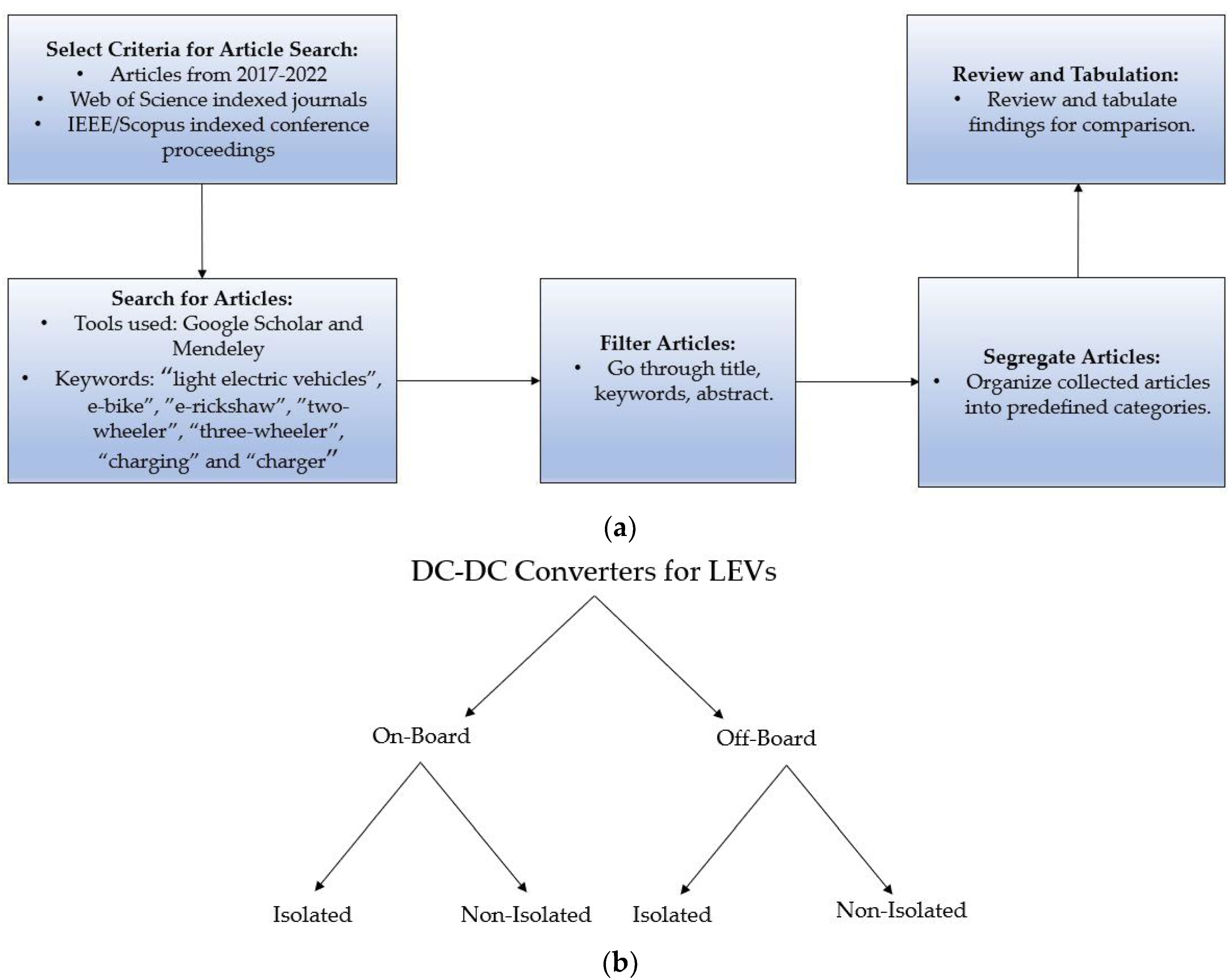
These articles were collected using Mendeley search tool and Google Scholar, and were searched using keywords such as: “light electric vehicles”, “e-bike”, “e-rickshaw”, “two wheeler”, “three wheeler”, “charging” and “charger”. Subsequently, these articles were further filtered by studying their titles and abstracts. Using the listed criteria, a total of 45 articles were collected. Finally, the review study of these articles was conducted by using the segregation shown in Figure 4. As per this classification, the selected papers were first divided into on-board and off-board charger topologies, and these were then subdivided into isolated and non-isolated converter topologies. The schematic diagram of the review methodology is also shown in Figure 4.
To review recent issues and future trends in research on DC-DC converters for LEV charging, articles from Web of Science indexed journals and IEEE and Scopus indexed proceedings are once again considered.

4. DC-DC Converter Topologies for LEV Charging

Design and analysis of power electronic converters is an integral aspect of LEV chargers. In this respect, researchers have proposed novel DC-DC converter topologies with optimized active and passive component count [17,18,19,20]. Furthermore, researchers have also leveraged soft-switching (zero voltage and/or current switching) of power electronic switches in recent works to reduce switching losses [21,22,23,24]. These converters may be used as part of two-stage or single-stage on-board/off-board chargers.
Irrespective of whether they are on-board, off-board or wireless, LEV chargers have evolved from fundamental DC-DC converter topologies. These include buck, boost, buck-boost, Single-ended primary inductor (SEPIC), Cuk and Zeta converters [25]. Super-lift Luo converters are also an option for when a high-current output is required [26,27].
Isolated DC-DC converters are preferred for chargers with higher power ratings. They provide galvanic isolation between the input and output stage by using a high frequency transformer. Isolated DC-DC converters can include single switch topologies (Flyback and forward converters) and multiple switch topologies (Push-pull, half-bridge, full, bridge, multilevel) [25]. Single switch topologies have the same characteristics as buck-boost converter [28]. In multiple switch topologies, bidirectional excitation of transformer is achieved by alternate operation of switches [29]. However, they have limitations such as transformer core saturation [30], and current stresses on primary-side switches due to discontinuous mode operation. Furthermore, half-bridge converters may be forced to operate at low switching frequencies at low input voltage conditions, leading to increased current ripples [31]. Multilevel converters are also a multi-switch option for high-gain applications. They also ensure reduced electromagnetic interference (EMI) due to reduced voltage jump [32]. Recently, researchers have proposed modified topologies such as bridgeless and interleaved topologies to achieve one or more of the following: improved charging efficiency, reduced voltage/current ripples, reduced size of passive components, and reduced component count. Furthermore, efficiency of charging may be enhanced by the introduction of soft-switching mechanisms using resonant converter topologies. Such topologies employ resonant capacitors in addition to the transformer leakage inductance to create resonance condition for switching. This can help in the reduction in switching losses at high frequency operation.
However, the most important evaluation for LEV charger design is its efficiency and charging time. Most LEVs take approximately 3–4 h to achieve full charge [4]. Since LEVs have immense potential in public transportation, improving charging time is of immense importance.

4.1. On-Board Charging

On-board charging remains the most widespread charging method for LEVs, mainly in part due to its simplicity in size and source availability. In a conventional AC-based LEV charging system, there are two stages: AC-DC rectification, followed by a DC-DC PFC stage to ensure smooth input current waveform, and another DC-DC converter to control the battery charging process. However, apart from two-stage LEV chargers, researchers have also reported on single-stage LEV chargers, where a single DC-DC converter is responsible for PFC and control of battery charging [33,34].
On-board chargers can exist on the vehicle itself or may be formed as part of the charging cable. Hence, a design objective of on-board chargers is to make it more compact, and hence increase its power density. This ensures that the charger module occupies minimum space on-board the vehicle. Other desirable operational characteristics of on-board LEV chargers are high charging efficiency, high power density and an acceptable input power factor.

4.1.1. Isolated DC-DC Converter Topologies

In LEV chargers, isolation can be achieved either by use of a transformer at the supply end or within the converter itself. The supply side transformer option is not feasible, as it requires the installation of a line frequency transformer, which has a bulky design. Hence, in subsequent topologies, researchers have employed high frequency transformers in charging converter design owing to their compact size. The provision of isolation in converters is advantageous in the following ways:
  • There is the obvious advantage of galvanic isolation between the battery circuit and supply, thus ensuring user safety.
  • The turns ratio of the high frequency transformer may be leveraged to achieve a wider voltage gain range, thus making the converter suitable for usage with a wider load range.
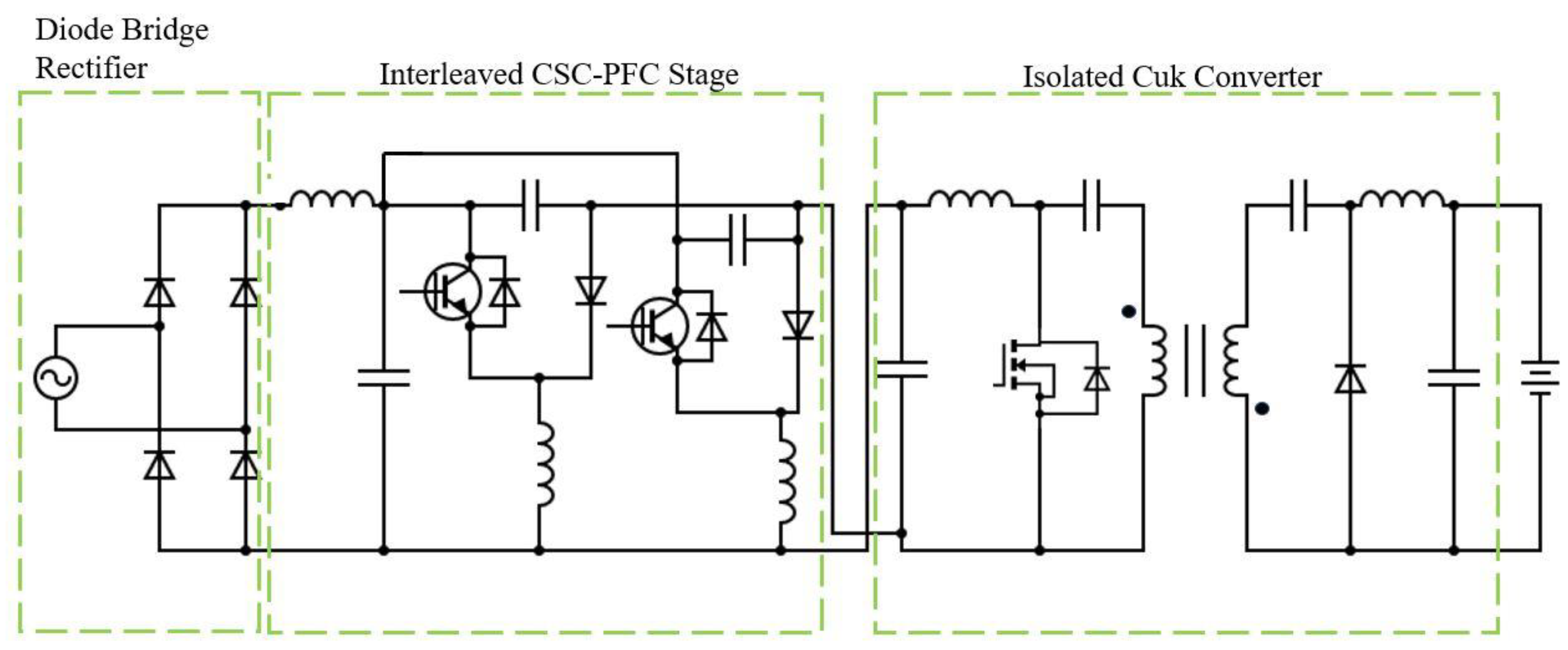
The conventional on-board LEV charger topology with front-end diode bridge rectifier (DBR) remains popular among researchers. For example, Singh et al. [35] presented a topology which used an interleaved canonical switching cell (CSC) at the front-end in conjunction with diode bridge rectifier for AC-DC conversion and power factor correction. This is further cascaded with an isolated Cuk converter at the back-end. This configuration exhibits simple control and is capable of charging batteries with voltages ranging from 24 V to 72 V. The circuit diagram for this circuit is shown in Figure 5. The CSC-based PFC ensures high power factor. The CSC is interleaved to reduce the size of filters and current ripples, and operates in discontinuous mode, which reduces the volume of magnetic components in the circuit, thus making it more compact. The back end Cuk converter operates in continuous mode, which reduces charging current ripples. The Cuk converter also allows for wide voltage gain variation and demonstrates robust performance in the event of supply voltage disturbances and varying battery voltages. However, the efficiency data in this work are missing.
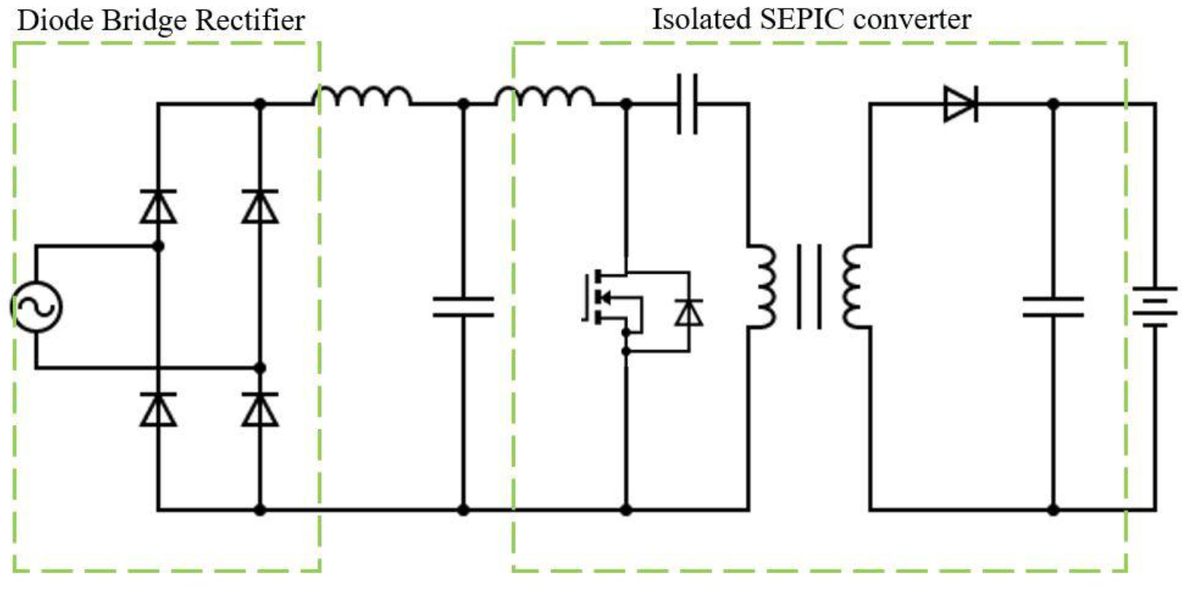
In yet another example, [36] presented an LEV charger which used a simple diode bridge rectifier in the front-end and an isolated SEPIC converter in the back-end. The charger schematic for this design is shown in Figure 6. The SEPIC converter has multiple benefits over the previously described Cuk converter, such as less susceptibility to EMI and inherent current limiting capability at the time of overload/startup. To reduce the size of magnetic components, this charger operates in discontinuous mode. Furthermore, the converter demonstrated satisfactory dynamic performance and posed minimum impact on supply power quality even during varying supply voltages, in compliance with guidelines set in the IEC 61000-3-2 standard. A charging current of approximately 20 A is observed and converter efficiency is approximately 80%. Furthermore, the input inductor of the SEPIC stage aided in power factor correction.
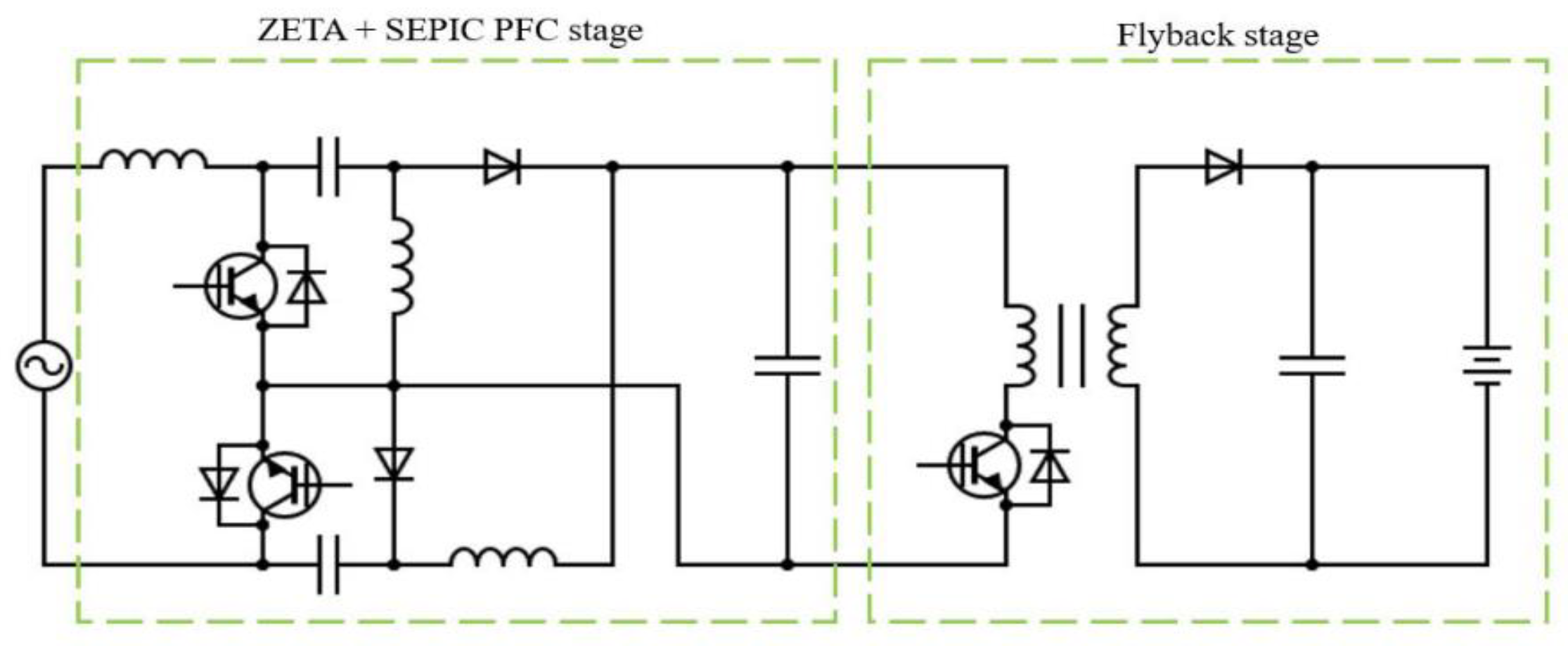
The authors of [37] proposed a two-stage converter which uses a combination of Zeta-SEPIC converter as the PFC stage, followed by a flyback converter stage, which controls the battery charging process. Furthermore, the Zeta and SEPIC converter combination controls the voltage of input DC link voltage of the flyback converter. The circuit diagram of this converter is shown in Figure 7. The Zeta and SEPIC converters operate independently in the positive and negative half cycle of the input AC voltage, and both operate in discontinuous conduction mode. The Zeta and SEPIC converters are chosen for this topology due to their comparatively better ripple current suppression capability. Furthermore, there is also a reduced number of active components, which helps in the reduction in conduction losses. However, the use of DC link capacitor with a voltage of 300 V may make the circuit bulkier. Additionally, the leakage inductance of the transformer may necessitate the use of an appropriate clamping circuit across the switch. A similar topology was presented in [38], which used a bridgeless modified Landsman converter instead of the Zeta-SEPIC stage. Yet another variant of [38]—described in [39]—used an interleaved Landsman converter, which resulted in a lower input current ripple.
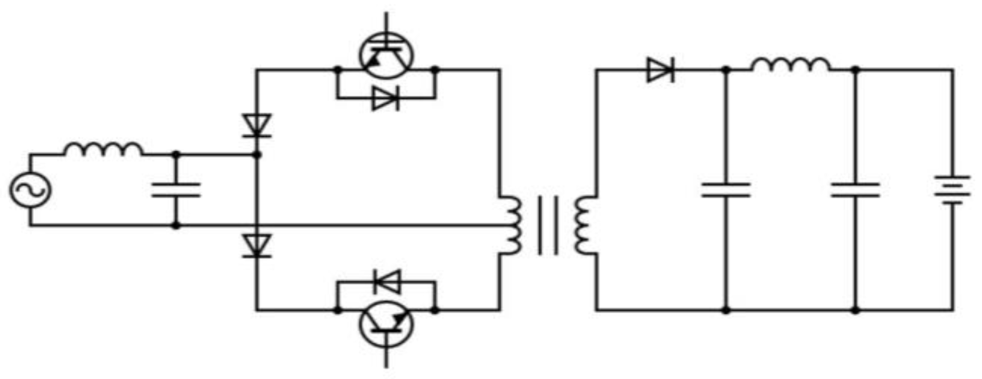
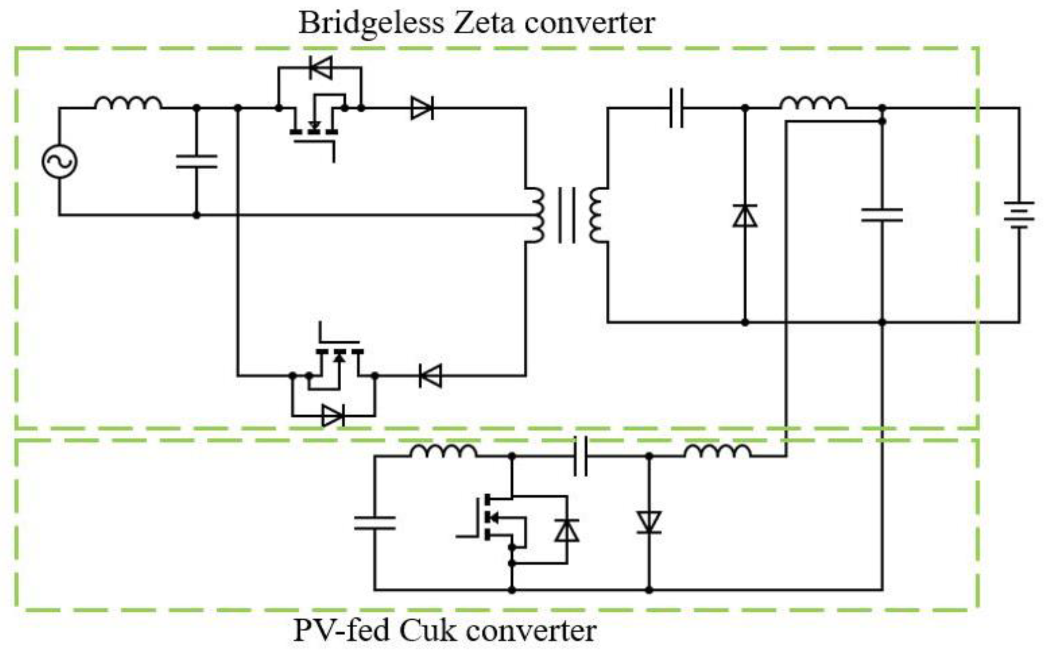
To reduce the number of semiconductor devices in charger topologies, researchers have looked to bridgeless converter topologies [17,18]. For example, the authors in [18] presented a single stage bridgeless isolated positive output Luo converter for LEV charging. This charger works for an AC input range of 85–265 V and ensures front-end high-power factor through use of Luo converter-based AC-DC converter topology. Eliminating the front-end diode bridge rectifier stage helps reduce component count and simplify design. Furthermore, the Luo converter-based topology achieves positive output polarity, which is contrary to prior implementations, which retained the negative output polarity. The significance of this feature is that this helps simplify output sensor design. Furthermore, the circuit operates in discontinuous mode to reduce magnetic component volume. This also reduces the switching/conduction losses of the switches in the circuit. The converter topology is shown in Figure 8. The authors of [19] use a bridgeless isolated Zeta converter shown in Figure 9, which also operates as a PFC converter, to charge LEVs. This on-board charger is further supplemented by a Cuk converter, which feeds solar photovoltaic (PV) power. This Cuk converter is controlled using the PV’s maximum power point algorithm. The high frequency transformer ensures a high voltage conversion ratio. Furthermore, the isolation design choice in this case is desirable to reduce ripples. However, while this design uses a smaller number of switches, its drawback is that the Cuk converter control does not depend on the battery status. Furthermore, the behavior of switches during switching operation is not elaborated in this work.
All the bridgeless converter topologies described above [17,18,19,20,37] also ensure improved power quality by reducing the THD of the supply current. This is done by the use of input inductance, which helps smooth the input current profile. Likewise, an output inductance is also incorporated in both circuits to reduce output current ripples. It is found through experimental results that the input current THD in these demonstrations is compliant with the IEEE-519 specified threshold of 5%. Furthermore, these bridgeless topologies have the advantage of reducing conductions losses (due to reduction in the number of semiconductor devices in the current path). Bridgeless converter topologies also exhibit poor performance related to EMI, as they have the tendency to introduce common mode noise on account of the presence of high frequency switch mode voltage [40]. This can result in degradation of supply current due to high ripples. Furthermore, because of the reduced switch count, the remaining switches of the bridgeless stage are subjected to high current stresses. For these reasons, research on two-stage converter topologies continues, owing to their improved EMI performance and manageable stresses on devices.
However, lack of soft-switching techniques in the topologies described above is a limitation. This may limit its operation at higher frequencies due to higher switching losses. To overcome this limitation, resonant converter topologies have been incorporated by researchers into on-board chargers [21,22,23,24,41,42,43]. This technique has been employed for numerous on-board chargers in conventional EVs [42]. For example, authors in [21,43] presented a two-stage e-bike charger; this charger uses a Cuk converter as the PFC stage, which is followed by a half bridge LLC (inductor-inductor-capacitor) series resonant converter, which controls the battery charging process. This charger ensures a wide output voltage range through variable DC link voltage control. The Cuk converter is chosen for the PFC stage due to its inherent input ripple current rejection capability. The circuit diagram for this configuration is shown in Figure 10. While the use of a half-bridge LLC converter helps in reducing the switching losses through zero voltage switching (ZVS), there is a drawback of increased component count in this circuit. Another recent implementation of a soft switched LEV charger is described in [22]. In this work, an LLC resonant full bridge converter is used, as shown in Figure 11. This configuration uses the resonant inductance of the transformer as a resonance circuit element, and the switching frequency is kept close to the resonant frequency, thus ensuring ZVS of the semiconductor devices. While a satisfactory efficiency of 96.4% is achieved, the component count of this configuration is on the higher side. A similar efficiency of 96% is achieved in [23], which uses a two-stage converter; the first stage is an interleaved buck-boost stage and the second is an isolated half-bridge LLC stage with synchronous rectification. The resonant capacitor size is reduced by using a split capacitor structure. The interleaved stage achieves natural PFC through operation in discontinuous mode, and the LLC stage helps achieve soft switching. The LLC stage is unregulated, thus reducing control complexity.
Another popular technique of modifying basic DC-DC converter-based LEV chargers comes in the form of interleaving. Interleaving—or multi-phasing—is a technique where multiple converter circuits are connected in parallel and turning on/off their respective switches after a phase delay as shown in (1) [44].
ϕ = 180/n
Here, ϕ denotes the phase delay (in degrees) and n is the number of phases connected in parallel. This process also tends to reduce the output current ripples. Another advantage of interleaving is that it increases the power handling capacity of the converter, thus lending itself to high current applications.
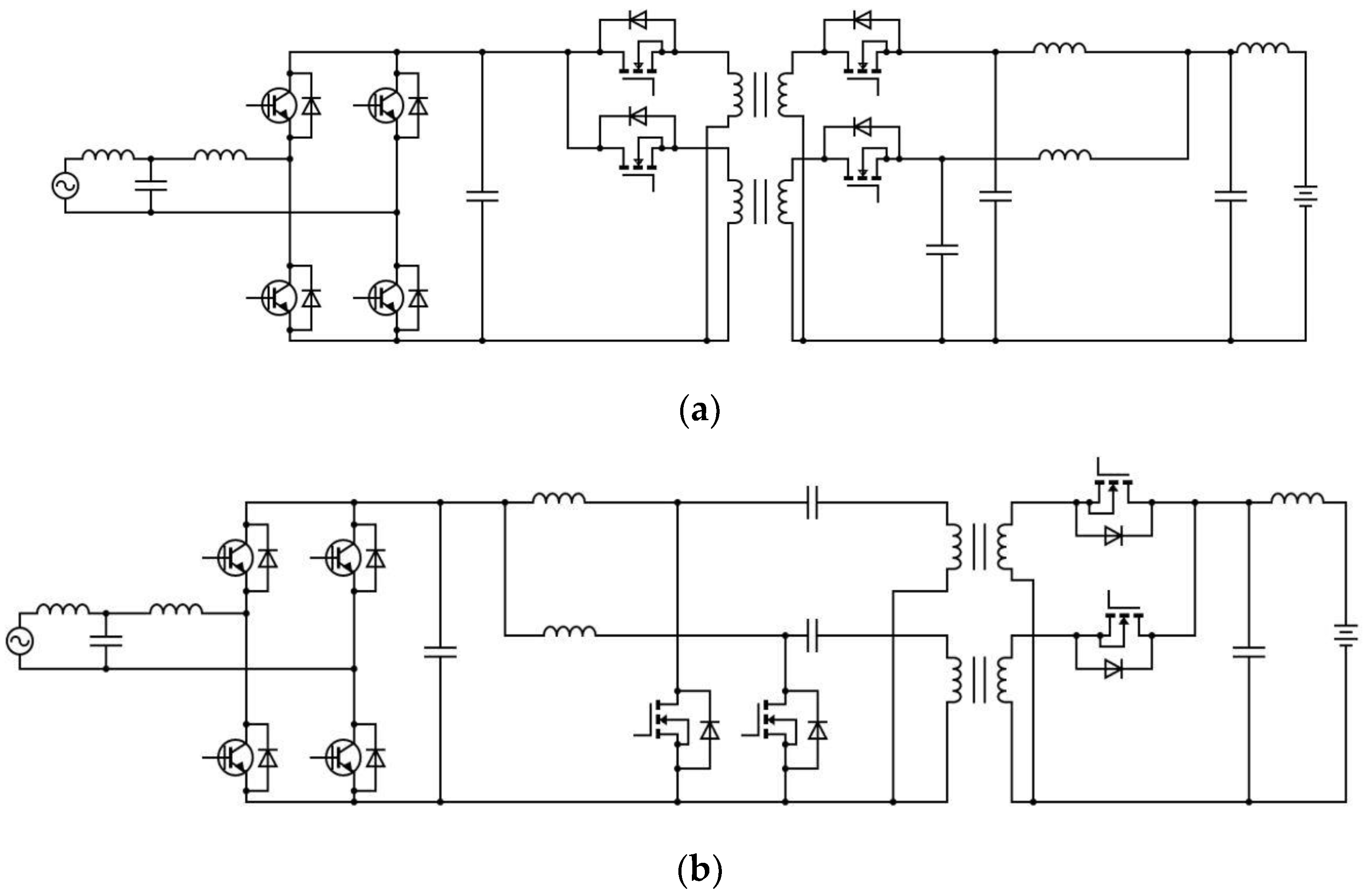
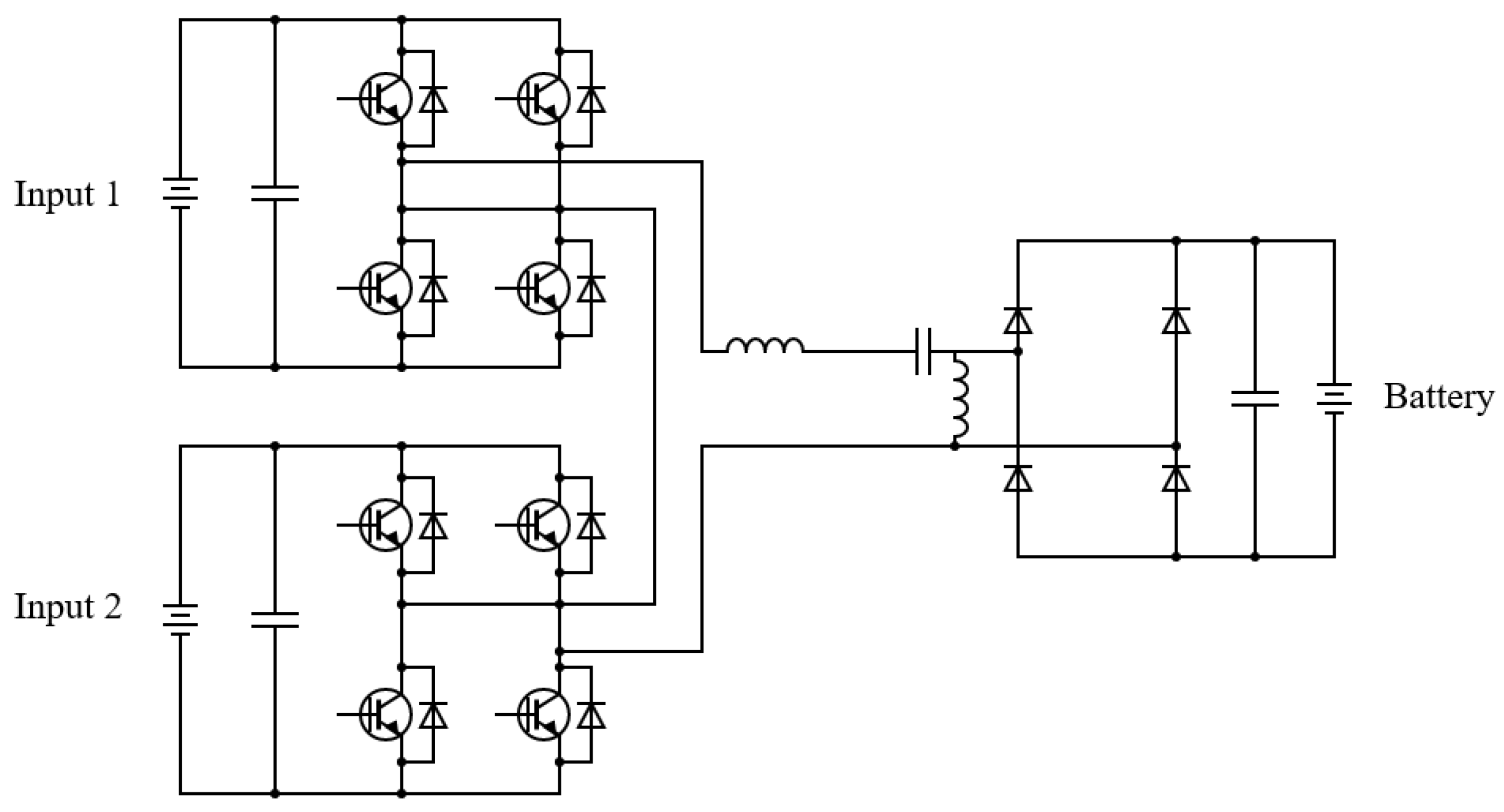
Authors in [45] demonstrate an interleaved isolated Luo converter, which is also capable of bidirectional power transfer. The front-end comprises a voltage source converter, which interfaces with the AC grid via an LCL filter. The back end comprises the proposed interleaved isolated Luo DC-DC converter, which operates with high efficiency at light load. The schematic for this charger is shown in Figure 12a. The system control design is performed so that there is a provision for fast charging, slow charging, and discharging (bidirectional) operations. A 40 A/20 A charging current is ensured for fast/slow charging of the LEV. Discharging mode is enabled depending on utility requirement (normally during idle hours). While this charger has minimum impact on grid power quality (minimum THD), exhibits unity power factor operation and seamless bidirectional operation, this paper lacks data on charging efficiency and charging time. Furthermore, this topology has a comparatively higher switch count.
In [46], the authors present a topology identical to [45], only replacing the interleaved isolated Luo converter with interleaved isolated SEPIC converter, as shown in Figure 12b. The charger front-end comprises a full bridge voltage-source converter and the proposed isolated interleaved SEPIC converter makes up the charger back-end. As can be observed, inductors on the input and output side help in suppressing current ripples, especially since this converter operates in discontinuous mode. Just like Singh et al. [45], this converter employs multistep charging for fast and slow charging. Depending on the supply side condition, this charger has vehicle-to-grid (V2G) capability. While this charger can work with minimal impact on supply side power quality, just like [39] this paper lacks data on charging efficiency and charging time. It also has a high component. A similar topology is used in [47], the only difference being that the authors use an isolated interleaved Zeta converter. The Zeta topology, owing to its output inductance, helps achieve continuous output currents, while interleaving further reduces current ripples. Furthermore, this converter topology also supports bidirectional operation. However, a significant drawback of this topology is the high component count of active devices, which may lead to higher switching losses at high frequency operation.
However, a significant concern with respect to interleaved converters is that the designer must pay attention to the current sharing between each parallel converter. This is imperative to ensure even distribution of the current carrying stress on each of the switches. Furthermore, another significant drawback of isolated converters in general stems from the leakage inductance of transformers. This leakage inductance does not allow current to change instantaneously, and during switching operation, this causes a voltage spike across the switch, thus potentially damaging it [48]. To counteract this effect, active or passive clamping circuits should be added with the switch, thus clamping its voltage to a fixed value [48]. However, this may come at the cost of increased component count.

4.1.2. Non-Isolated Converters

Owing to the comparatively low charging power required for LEV batteries, researchers have found it feasible to implement non-isolated converter-based charging topologies. One of the key advantages of non-isolated converter-based chargers is that due to the absence of isolation transformer, there is a big reduction in charger module volume. Furthermore, there is an improvement in efficiency and power density [49]. However, a general drawback of non-isolated converters is their low voltage gain range. This issue may be addressed by using switched capacitor or coupled inductor topologies [48,50,51]. Another drawback of non-isolated converters is the lack of galvanic isolation between the battery circuit and supply, which is disadvantageous from a safety standpoint.
In this regard, the authors of [25] have comprehensively reviewed on-board unidirectional chargers, albeit for both short- and long-distance EVs. The authors segregated these chargers into fundamental converter topologies (buck, boost, buck-boost, Cuk, Zeta, SEPIC [52], Luo) and modified converter topologies, in which the aspects of fundamental converters are tweaked to enhance one or more features. Modification techniques for fundamental converters often include interleaving, bridgeless topologies, or both. The consequent effects of these modifications may include, but may not be limited to, reduced ripples in input and output current and improved efficiency.
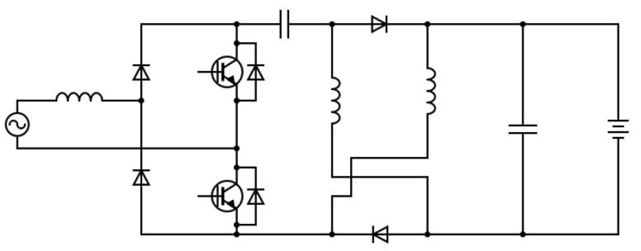
In non-isolated converters for LEV charging, recent publications have utilized switched inductors to enhance the voltage gain. For example, [53] describes one of the more recent implementations of non-isolated bridgeless LEV chargers. In this work, the authors have presented a single stage bridgeless on-board SEPIC converter-based charger, which uses a switched inductor structure. This charger configuration is shown in Figure 13. As evidenced in the circuit diagram, the identical switched inductors are charged and discharged in series and parallel, respectively—thus helping increase the overall gain of the charger. This converter achieves compact design and reduced component count, owing to absence of transformers. These switches also operate in discontinuous mode, which reduces the switched inductor size. Since a SEPIC topology is used in this work, there is an added advantage of simplified sensing of output voltage since the SEPIC converter delivers a non-inverted output voltage.
The authors of [54] present another charger based on bridgeless non-isolated DC-DC converter with switched inductors. In this work, the authors present a bridgeless Cuk DC-DC converter-based single stage charger, and as in [46], utilize a switch inductor configuration. The only difference is that the switched inductor and diode’s placements are interchanged (much like the fundamental SEPIC and Cuk converter). The converter’s switched inductors are also charged and discharged in series and parallel, respectively. Discontinuous conduction is observed in switches, thus reducing the output inductor size. The component count is also identical to that of [53].
The proposed converters demonstrated satisfactory conversion efficiencies—92.5% for [54] and 93.3% for [53]. This is partly owed to the fact that these two topologies are single stage, thus greatly reducing conduction losses. Furthermore, due to the presence of switched inductors, the single-stage converter helps achieve wider gain range. Additionally, these implementations exhibit minimal impact on the supply current THD, as per IEEE-519 and IEC 61000-3-2 standards. However, there might still be sufficient conduction losses due to a maximum of three diodes providing a conducting path in each positive or negative cycle. Furthermore, due to the use of switched inductors in this circuit, there is also a potential for voltage spikes across switches [55]. This may necessitate the use of voltage clamp circuits alongside the switches.
Sharma et al. [56] present a two-stage non-isolated bidirectional onboard charger LEV. The front-end includes a voltage source converter which converts the AC supply to DC, and controls grid current power quality. The following stage is an interleaved buck-boost converter, which regulates the battery charging current. The bidirectional nature of the given topology makes it suitable for vehicle to grid (V2G) operation. However, this circuit suffers from a high switch count.
Another recent development in non-isolated topologies is the development of quadratic topologies. These topologies have the advantage of achieving high currents at the battery end. Kumar et al. [57] developed a quadratic buck boost converter for LEV charging. This has the advantage of operation at discontinuous conduction, helping to further reduce component size. However, the number of passive components is comparatively high. Additionally, there may be scope for reduction in supply current THD due to DBR front end. This topology is shown in Figure 14.
Finally, [58] presents a detailed review of on-board bidirectional DC-DC converters for EV charging, which also include Level 1 (up to 3.7 kW) and Level 2 (3.7–7 kW) chargers. This work investigates two-stage and single-stage charger topologies in detail—standards, major components and some converters for PFC and DC-DC stage. The authors emphasize some of the challenges pertaining to single stage on-board chargers: complex control strategy, large output current ripple and sophisticated design. Furthermore, some future trends are highlighted such as advances in topology (use of interleaved converters), semiconductor electronics (wide bandgap devices) and thermal design, to name a few.
A comparison of all the isolated and non-isolated on-board chargers is shown in Table 2.

4.2. Off-Board Charging

Considering the potential impact of on-board LEV chargers on supply power quality and the drive to make LEVs more efficient, researchers are looking towards off-board and DC-based LEV charging. This mode of charging has a comparatively lower number of conversion stages, thus leading to more efficient charging. Furthermore, there are limited concerns with respect to supply power quality, owing to the DC power supply. DC-based charging eliminates the front-end AC/DC and PFC stage altogether, thus leaving only a DC-DC stage which controls battery charging. Normally, DC chargers exist as off-board chargers [3], and it is a relatively nascent concept in in LEVs. Thus, it has not seen widespread commercial use yet. Notable commercial uses of DC fast charging are highlighted in [5,59].
Another interesting aspect of off-board DC chargers is the potential for solar PV integration at the supply end. Certain works report a dual input EV charger [60], which features a three-port charger powered through a 3-phase AC grid and a standalone PV system. In the event of low solar irradiation, the EV charger operates in grid-connected mode. One of the key advantages of this setup is the ease of burden on the AC grid due to the use of solar PV power. Furthermore, this type of charger is also capable of operating in V2G mode, during times when the connected EV is idle for long hours. The PV source is connected via a unidirectional DC-DC converter, which is responsible for maximum power point tracking. A bidirectional AC/DC converter ensures charging from the grid and allows a possibility for V2G. Finally, the unidirectional DC-DC converter interfaced with the EV ensures charging control.
Nevertheless, the same segregation applies here as in the case of on-board chargers: (i) isolated, and (ii) non-isolated chargers. There may be a valid argument for use of isolated converters if the voltage level is sufficient. However, for low power levels, it is feasible to pursue non-isolated topologies.

4.2.1. Isolated Converter

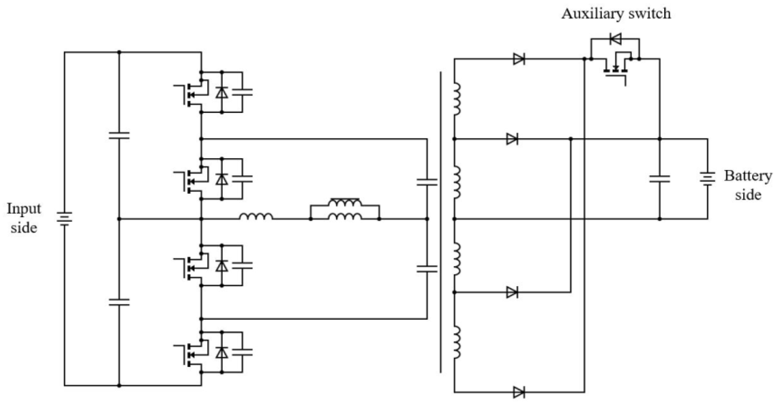
Off-board chargers with isolated configuration have been presented in recent literature, owing to their superior voltage gain range and potential for providing soft-switching capability. Authors of [16] presented an LEV charger which derives input power from a DC microgrid. This gives credence to the concurrent research on EV charging and DC microgrid. This LEV charger employs an LLC structure for soft switching of semiconductor devices. This implementation also ensures wide output voltage capability through the use of variable winding sets on the secondary side of the transformer, as shown in Figure 15. For larger loads, an auxiliary switch operation ensures a greater turns ratio. Furthermore, a cascade switch structure is used on the primary side to reduce voltage stresses, thus allowing usage of switches with lower rating. Furthermore, two capacitors are used on the primary side to provide resonant condition for soft switching, and to provide split input voltage balance. Zero voltage turn-on and zero current switching turn-off is ensured for active switches and fast recovery diodes, respectively. This is due to the variable frequency switching scheme—pulse frequency modulation (PFM)—employed, in contrast to the conventional pulse width modulation (PWM). While this converter exhibits satisfactory performance for variable load, there are no data on efficiency reported. Furthermore, there is still scope for reduction in switch count, and the use of an additional switch for wide load operation may increase control complexity. Optimization of efficiency for the LLC-based charger is also a research avenue that can be taken up in subsequent studies [61].
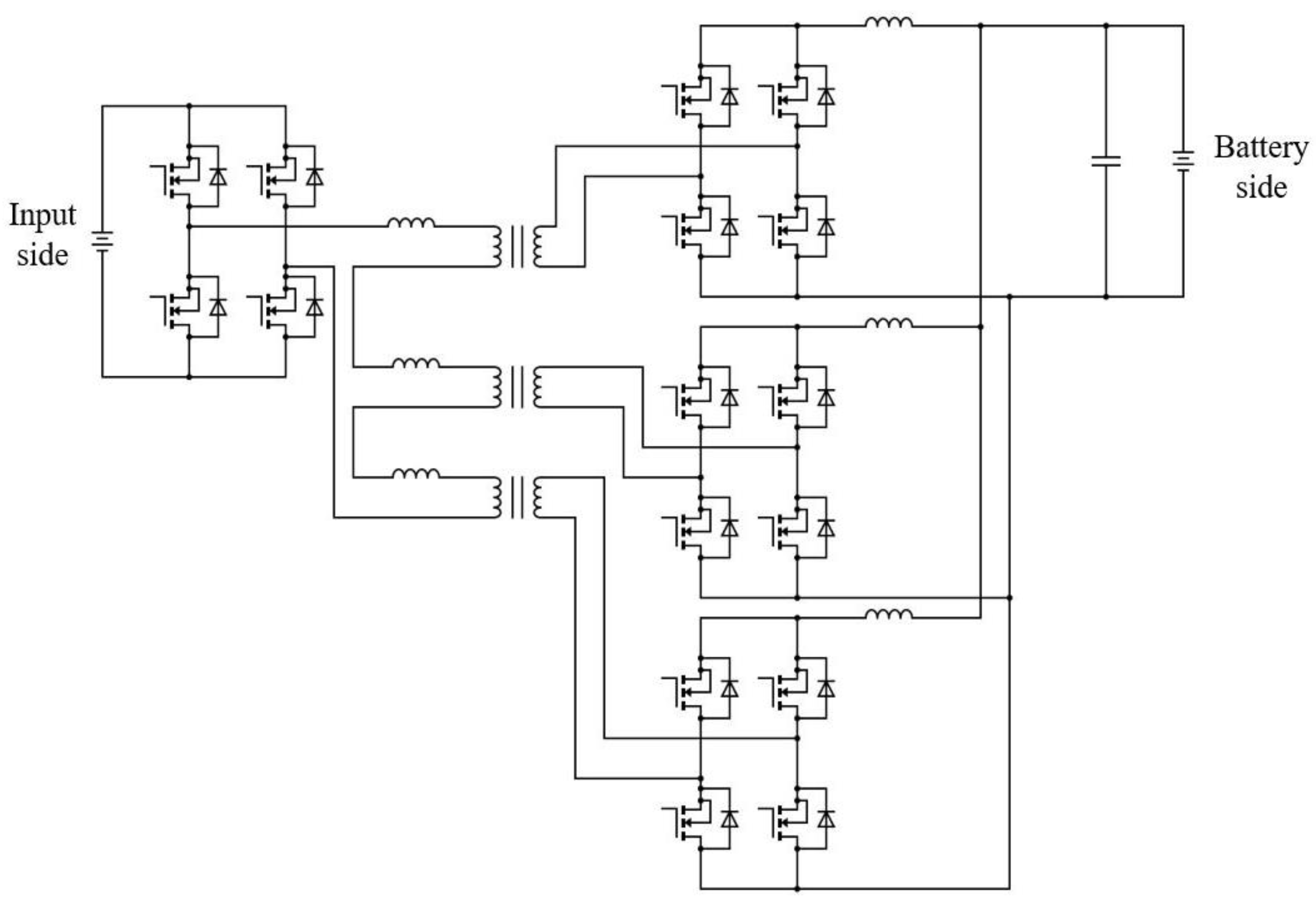
Another suitable candidate for isolated LEV charging is the dual active bridge converter [62,63,64,65]. In [63], the authors presented a multi-module dual active bridge converter with input-series output-parallel topology starting from the transformer secondary end, as shown in Figure 16. On the primary side, a single full bridge converter is used. The modularity of the system ensures scalability according to the load connected at any given time and ensures redundancy. Furthermore, the converter also maintains output current sharing and input voltage sharing through appropriate control scheme. Through experimental results, this converter topology achieves a high overall charging current of 94 A, which is fed in positive and negative pulses. While this ensures fast charging, this work lacks data on charging efficiency and charging time. Furthermore, the given topology has high component count and there may be issues related to high frequency transformer leakage inductance, such as switching transients and duty loss.
Moreover, one limitation related to dual active bridge converters is the EMI issue that may result from large deviations in input or output voltage, or light loads [66]. To increase compactness, the dv/dt limit may be pushed, and issues such as current ringing may occur.
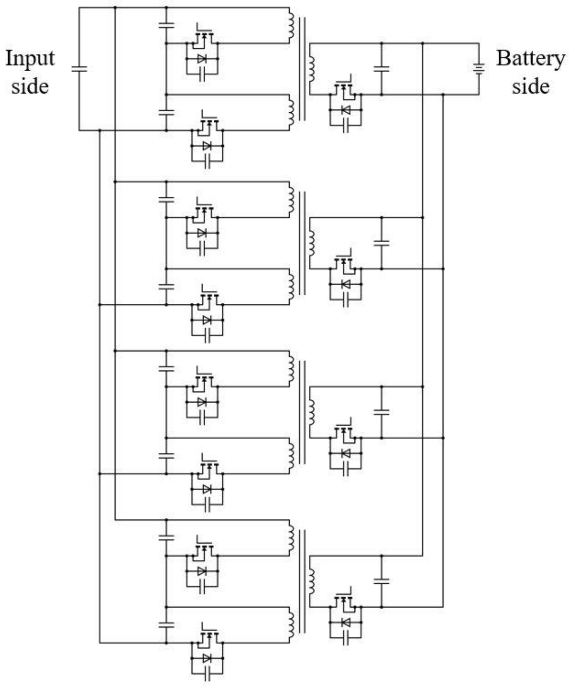
One more potential candidate for implementing isolated LEV chargers is the flyback converter. The use of flyback converter for LEV charging is exemplified by works [4], and [60]. In [60], a quasi-resonant flyback converter is presented for charging purpose, which is also interleaved to reduce component size. This interleaved converter forms part of a 10 kW three-port charger, which is interfaced with a solar PV power supply and grid power supply. In this three-port charger, there exists a common DC-link, which facilitates exchange of power between the three sub-converters, and the given interleaved flyback converter forms the interface between the EV and the common DC link. The interleaved flyback converter also facilitates bidirectional operation, like the dual active bridge converter—thus achieving V2G capability. The presented converter is operated in quasi-resonant mode in both charging and V2G mode, which has numerous advantages, such as reduction in switching losses due to zero or low voltage switching (ZVS/LVS), reduction in turn off losses from the use of resonant capacitors, as they absorb excess energy during turn-off operation, and the reduction in RMS current due to boundary conduction operation of the converter. Ultimately, the presented interleaved flyback converter displayed a good peak efficiency of 98.8%. However, the component count is equal to the dual active bridge converter, and there is a scope of reduction in the same for use at lower power levels. The configuration of the given converter is shown in Figure 17.
A similar topology for DC charging of LEVs is shown in [4], which uses the same quasi-resonant interleaved flyback structure, albeit for a lower power level. This converter was implemented as part of an on-campus charging station for e-bikes, e-scooters, and e-carts. A significant aspect of this charger was that it was primarily fed from a 48 V DC nano-grid, which constitutes a standalone PV power supply, a backup battery, and a grid connection. In times of lower solar irradiance, power is fed from the backup battery, otherwise it is fed from the grid. Since the charging power is much less compared to [60] at 2.6 kW, a dual interleaved flyback converter is used for this application. The primary and secondary currents of the flyback converter are controlled through current mode control, and quasi-resonant switching is imposed on the switches. While the circuit design is much simpler compared to [60], this work lacks data on charging efficiency, and the charging times of the listed LEVs—which range from 3 to 5 h—may be further optimized through increase in charging current.

4.2.2. Non-Isolated Converter

Considering the low charging power requirement for LEVs, non-isolated converter topologies remain popular among researchers. In the case of DC charging, reported non-isolated converters are mostly based upon conventional DC-DC converter topologies such as buck-boost, Cuk, and SEPIC, as seen in the case of on-board non-isolated chargers.
One significant trend observed in recent implementations of non-isolated LEV chargers is the use of solar PV power supply as one of the inputs, or as the sole input. Design of such a system is described in [67], which takes into consideration the solar irradiation in a particular location. One prominent example of implementation of such a charger is described in [68]. In this work, a SEPIC converter is described by employing a solar PV input, thus resulting in a self-reliant off-board charging system. The converter operates in continuous mode to minimize voltage and current stresses on circuit elements, while also reducing current ripples. To further reduce charging current ripples, a small inductance is placed near the battery. Furthermore, this SEPIC converter, which normally controls battery charging process, also controls the MPPT of the solar PV input, thus addressing the issue of multiple conversion stages in standalone PV-based charging systems. This system is tested under variable solar irradiation and temperature variations, and it shows satisfactory performance in terms of MPPT tracking and charging efficiency. However, there is no clarity in the charging efficiency data reported in this work. Furthermore, standalone PV systems require an auxiliary battery storage to maintain power continuity in times of low solar irradiation. This aspect is not explored in this work.
Authors of [69,70] have also presented non-isolated charger topologies integrated with standalone solar PV power supply. The work in [69] presented a comprehensive design and analysis of an EV charger with standalone PV power supply. For the charging process, a first quadrant DC-DC buck converter is used. The auxiliary battery charging/discharging is controlled by the two-quadrant bidirectional DC-DC converter. This work also considers the sizing of PV power supply and auxiliary battery energy storage, based on typical variations of solar irradiation. This system is then tested under dynamic conditions—variable solar irradiation and a disconnection of PV supply—where it shows satisfactory performance. However, the charging efficiency data are missing in this work. Furthermore, an extra DC-DC boost stage is used in this work for PV MPPT control which may have an impact on the charging efficiency.
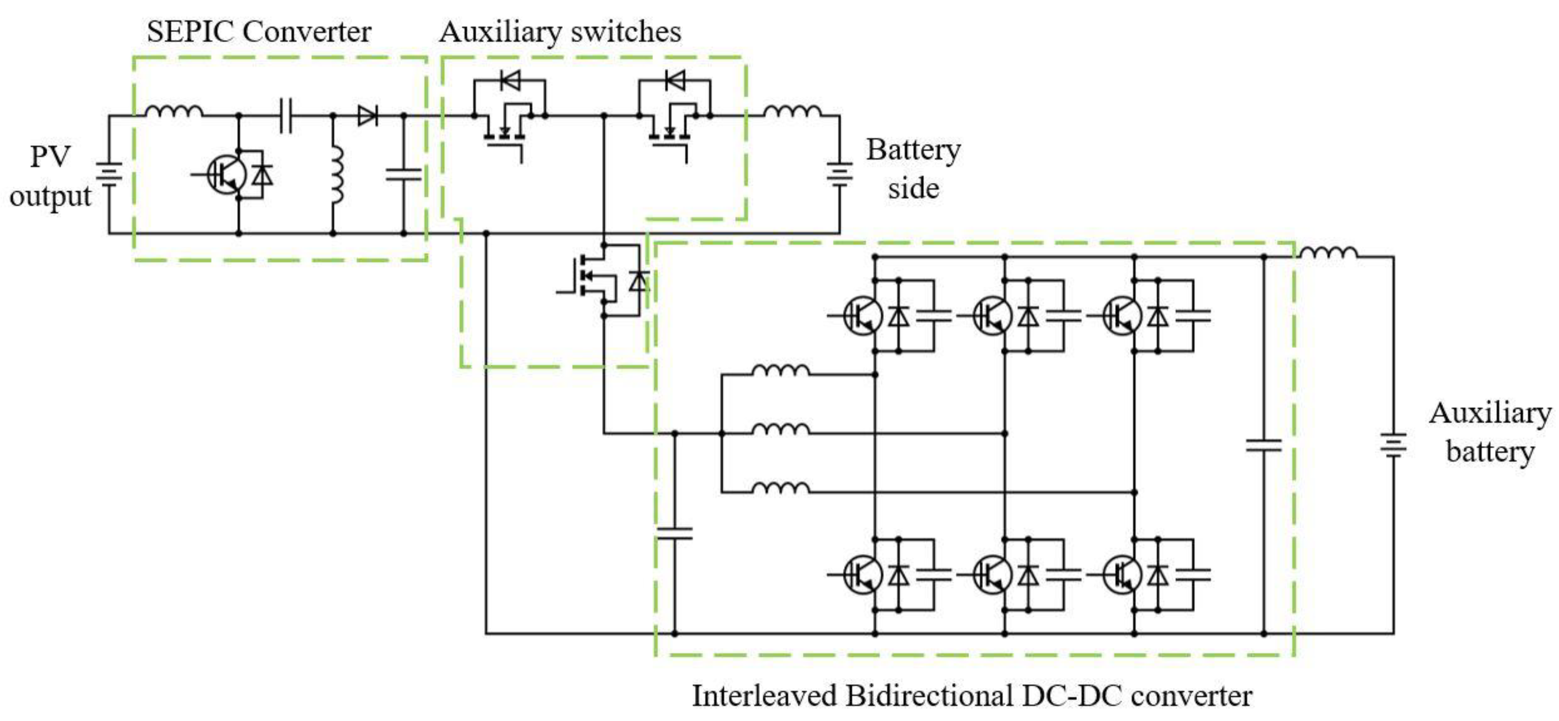
Similarly, in [70], the authors presented a standalone PV-based non-isolated EV charger system, which also employed an auxiliary battery energy storage system. The power flow between the PV supply, EV battery and the auxiliary battery is coordinated by the use of three auxiliary switches. Operation of these switches depends on solar irradiation level. A schematic of this charging configuration is shown in Figure 18. As can be seen from this figure, the standalone PV supply uses the SEPIC converter to charge the EV battery and the auxiliary battery is charged/discharged through the interleaved bidirectional converter. Furthermore, to improve efficiency, the interleaved bidirectional converter is operated in discontinuous mode. The system is then tested under dynamic conditions—namely three different cases of varying solar irradiation. In all these cases, the charging efficiency is observed to be approximately 96%, which is satisfactory. Despite these promising results, the given topology has a relatively high switch count on account of the use of auxiliary switches, which may lead to increased control complexity.
Another development in non-isolated topologies comes in the form of transformerless LLC converters. In this regard, the authors of [71] presented a transformer-less multilevel LLC DC-DC converter. This topology overcomes the limitation of conventional half-bridge and full-bridge LLC topologies, i.e., degraded performance at high frequencies. The transformerless nature of this converter also reduces the converter size and cost. The LLC stage also ensures ZVS operation near the resonant frequency. Lastly, the observed efficiency is approximately 97%. However, this topology suffers from drawbacks such as high switch count and high frequency selectivity for ZVS. The schematic is shown in Figure 19.
A summary of discussed off-board topologies is described in Table 3.

5. Summary, Gaps, and Improvement Measures in Reviewed Literature

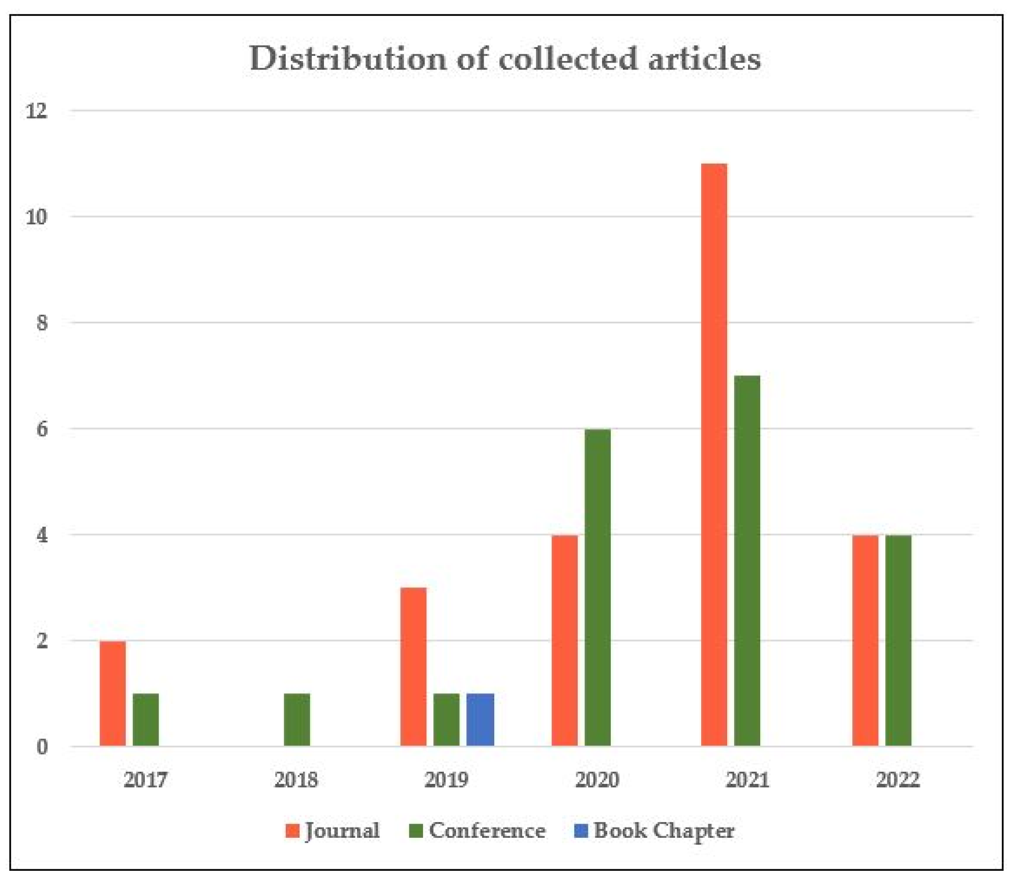
Figure 20 shows the distribution of collected articles—by type and year—for this review study. One key takeaway from this plot is the increase in published research articles over the five-year timeframe considered. Furthermore, the research output has increased considerably since around 2020.
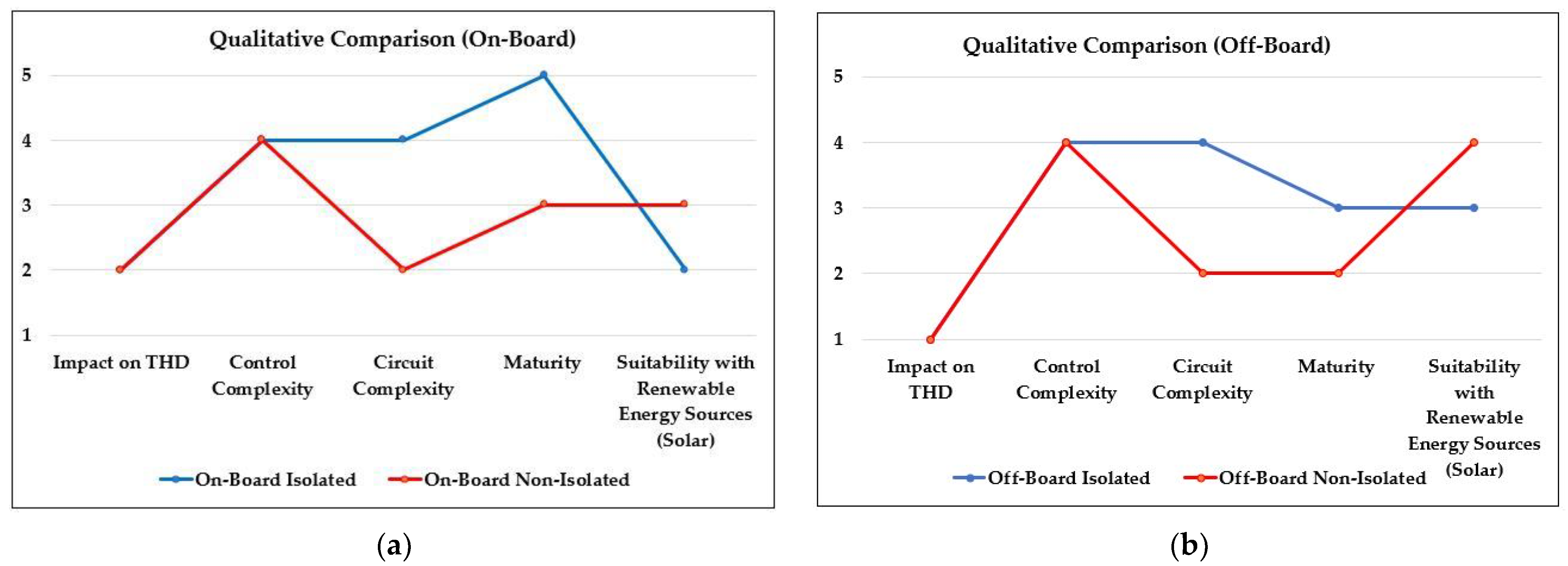
From the reviewed literature, it is evident that on-board charging continues to remain a highly researched topic. This is a testament to the level of maturity this technology has gained over recent years. It is also seen that within on-board charging, isolated topologies are widely preferred. This is because of the safety aspect stemming from galvanic isolation between supply and vehicle, and the inherent capability for soft switching. However, non-isolated topologies are a viable solution as it helps increase power density. This makes the charger circuit more compact and cost-effective. One gap that needs to be addressed in on-board chargers is to find an optimal balance between component count and converter performance. This is evident in flyback converter-based topologies. In these, transformer leakage inductance causes voltage spikes which requires the use of snubber circuits, thus increasing component count.
On the other hand, research on off-board charging—while not as mature as off-board technology—has been gradually gathering pace in recent years. Like on-board, the aim must be to strike a balance between component count and converter performance. LLC converters, for example, can achieve soft switching but at the cost of high switch/component count. Furthermore, the issue of control complexity also needs to be addressed, since there is a reduction in power conversion stages.
One important takeaway from reviewing non-isolated off-board technology is the integration of solar PV power supply in the charging system. However, application of off-board chargers with standalone PV supply and DC distribution systems is an encouraging trend. To fully unlock the potential of this method, future works can focus on topologies with simple design and controls—managing both PV maximum power point tracking and charging control. Furthermore, the sizing of backup battery bank is another significant research area, which has implications on the viability of a standalone PV-based charging station.
Furthermore, efforts must be made to unlock the vehicle to grid (V2G) potential of LEV chargers. One way to do this is by eliminating the DBR stage and using a bidirectional converter. Apart from the obvious advantage of V2G potential, they are also characterised by low component count and increased power density, as compared to multistage converters which use a DBR stage. Bidirectional functionality is especially beneficial for non-isolated topologies, as evident in works such as [72,73] which also demonstrate high step-down gain. As an example, Hosseini et al. [73] presented an extendable quadratic converter, which was suitable for both grid-to-vehicle (G2V) and V2G capability. This converter was characterised with simple operation, low component count, and also a common ground between supply and battery.
Based on the articles reviewed, a qualitative comparison of on-board and off-board DC-DC converter topologies are presented in Figure 21. This comparison includes characteristics such as impact on supply THD, control and circuit complexity, technology maturity and suitability for PV integration.

6. Challenges and Future Trends in LEV Charging

6.1. Wireless Charging

While conductive modes of charging—both on-board and off-board—remain popular for LEV charging due to their relative simplicity of implementation, there remain certain issues with respect to its usage. Physical connectors may suffer wear and tear due to regular usage and environmental factors. This may result in safety issues for the vehicle and the user. To address these issues, researchers are gradually exploring techniques such as wireless power transfer. Figure 22 shows the schematic block diagram for wireless charging, showing components such as transmitting and receiving coils, and compensators.
Ever since the breakthrough in wireless power transfer by authors of [74]—who demonstrated a system which could transfer 60 W over a 2 m distance—several advancements have taken place in wireless power transfer, with improvement in transfer efficiency and transfer distance [75,76,77,78,79]. Works such as [80,81] have explored concepts and trends relating to the adoption of wireless charging in electric vehicles. In [80], different wireless charger topologies—based on two winding model—are compared, and various compensation techniques validated for enhancement of power transfer capability. Furthermore, safety guidelines and scope for integration with renewable energy sources are also touched upon in this study. The authors of [81]—in their study of trends in EV charging infrastructure—also explore concepts and trends in wireless power transfer-based chargers: near field (inductive and capacitive) and far-field (electromagnetic). A state-of-the art on these chargers is presented, and it is inferred that inductive power transfer-based chargers demonstrate superior characteristics—power density, and efficiency—over capacitive power transfer-based chargers. However, capacitive power transfer is superior in terms of misalignment tolerance. Lastly, far field power transfer and wireless dynamic charging—charging of vehicles during movement—are highlighted as means to reduce range anxiety among users.
In recent years, many wireless charger topologies have been reported by researchers in [4,82]. In their reported integrated solar PV-based LEV charger, authors of [4] also discuss the provision for wireless charging of e-bikes. This charger is based on the inductive charging principle, where the transmitting coil is located under the charging tile, and the receiver coil is integrated into the e-bike kickstand. The use of capacitors in transmitter and receiver circuits help enhance the power transfer capability by compensating for reactive power and enforcing a resonant frequency. The misalignment issue is also addressed in this work by using auto-resonant frequency control, which uses an inner control loop to set the system to its natural resonant frequency.
To enhance the capability of wireless charging, researchers have recently made a development wherein an intermediate coil or split primary coil is employed within the system [83,84,85]. Authors of [84] have presented a three-coil structure-based wireless charger for the e-bike. The given scheme does not employ a communication link to achieve constant current and constant voltage control. Instead, it employs a primary-side load identification technique to control the transition between constant current and constant voltage mode. This transition is further achieved by engaging two primary-side switches. This further eliminates the sensing requirement on the secondary side. Likewise, authors of [83] have presented a two/three coil hybrid topology, which uses two and three coils to achieve constant current and constant voltage, respectively, to charge e-bikes. Furthermore, this scheme can be used to charge multiple e-bikes at once. For compensation of reactive power, an inductor array is attached on the primary side, which facilitates the charging of multiple e-bikes. Both described topologies demonstrate approximately the same maximum efficiency at 91%. However, these works do not address the issue of misalignment between the transmitter and receiver coils.
A summary of the discussed wireless charging topologies is shown in Table 4. It is evident that wireless charging in LEVs is a nascent research topic, and it is expected that further improvements can be made to efficiency [86] and other aspects of these systems in the future. For example, one of the key issues in inductive charging is the effect of misalignment between the transmitter and receiver coils. In this regard, one solution might be in the form of a hybrid of inductive and capacitive charging—an approach that can lead to improved efficiency and increased misalignment tolerance [81]. Furthermore, another avenue that can be explored by researchers in the context of LEV wireless charging is dynamic wireless charging, which can help in reducing range anxiety among users and lead to wider adoption of LEVs. Another key aspect that needs to be addressed by researchers is safety relating to wireless power transfer [87]. One of the ways to address this is by working on shielding methods in the wireless charging system [88], which can have implications from a safety point of view.

6.2. Fast Charging and High-Current Converter Topologies

One way to achieve fast charging times is to use high current DC-DC converter topologies. For high current applications, converters with low/high step-up/step-down voltage gain range have been reported numerous times in recent years. One straightforward way to achieve this goal is to use isolated topologies, which leverage the transformer turns ratio to improve the gain range. Works such as [89,90,91] use similar techniques for low voltage high current applications. The authors of [89] used a phase-shifted full bridge converter followed by a current doubler rectifier to achieve this objective. On the other hand, [90] demonstrated a low voltage soft-switched converter which utilized series-connected half-bridge cells on the primary side—operated in an interleaved manner—and parallel-connected single-diode rectifiers on the secondary side. However, one significant limitation of such implementations is the effect of leakage inductance stemming from the high frequency transformer. This inductance can contribute to voltage spikes across the switches, resulting in damage. To overcome this, additional circuitry—active and passive clamping circuits—may be used, which may increase the cost.
Owing to this glaring disadvantage of isolated converter topologies, non-isolated DC-DC converters have also been widely reported for high-current applications [92,93,94,95]. The authors of [92] demonstrated high gain of step-down DC-DC converter for high current applications such as voltage regulators for microprocessors, power supply for telecommunications, etc. To achieve this high gain at moderate duty cycle, the authors used transfer capacitors and a built-in transformer in this topology. The sizes of these inductances are further reduced due to the use of interleaving technique for two main switches and two synchronous switches. Furthermore, the extent of coupling of inductors also influences the current ripples. The step-down gain of this converter is augmented on account of the transformer turns ratio. While the peak efficiency of the proposed topology is observed to be around 95%, there is room for improvement by reduction in freewheeling currents, which may lead to duty loss. Fatahi et al. [94] and Amiri et al. [95] both use the interleaving technique in their presented topologies. While [94] uses auxiliary circuits with active switch to achieve soft switching, [95] achieves the same result without the use of active switches. In the case of [92,95], high gain on account of turns ratio of coupled inductors, in contrast to [94] is achieved. Other wide-gain topologies have been reported by [96,97], which also achieve inherent current sharing among switches. Converters with quadratic gains are also viable candidates for high current applications [73].
Another way of achieving fast charging in LEVs is through battery swapping. This practice involves the removal of discharged battery and its replacement with a fully charged battery. The concept of battery swapping has gained traction for conventional EVs in recent years, in particular because of their potential to facilitate V2G capability [98,99,100]. Battery swapping stations also allow for easier integrating with renewable energy sources [101]. However, there are safety risks in battery swapping for conventional EVs [102]: sparks during battery changing and degradation of contacts. Safety risks are relatively low for the case of LEVs, mainly due to their lower operating voltage. However, there are still disadvantages such as larger infrastructure requirements.

6.3. Fully Renewable-Based Charging System

Another significant development in the field of LEV charging is the incorporation of renewable energy sources into the charging infrastructure. The main motivation behind this is to alleviate the burden of supply from the AC grid [60]. Works such as [4,60,103,104,105,106,107,108] have presented topologies that integrate solar PV sources into the EV charging systems. Furthermore, a comprehensive review on this subject is presented by [109], which deals with different aspects of a PV-based EV charger—power electronic converters, energy storage units (ESU), energy management, to name a few. The authors of [110] have also reviewed the performance of grid-connected and standalone PV-based EV chargers. The authors of [4,60,103,104,105] have considered the charging of LEVs with roof-mounted PV panels for their on-board charger implementation. Singh et al. [104] also considered PV power supply as one of the inputs for the isolated SEPIC converter that they demonstrated for their on-board charger. However, its drawback was that the battery charging process from PV input was solely controlled using MPPT, which did not take the battery current or voltage status into consideration. The work described in Kumar et al. [103] has the same drawback.
However, it is also possible to integrate LEV charging systems with standalone renewable energy sources—particularly solar PV [111]. In this way, the charging process can be made truly sustainable, thus removing any dependence on the AC grid. Furthermore, this type of charging is suitable for areas with limited accessibility to the grid. Consequently, certain research works based on this have been reported in recent years [69,70]. However, while such works have shown satisfactory performance in terms of charging efficiency, there are still certain aspects in system implementation that require attention:
  • Integration with solar PV will result in an increased number of power conversion stages, on account of the addition of a power converter for PV MPPT. To counteract this, a single power conversion stage can be used, which may be responsible for both maximum power point control and battery charging control. While such a scheme may result in improved efficiency, the complexity of control may also increase.
  • Another key challenge in implementing such systems is the continuity of power supply. Supply intermittency may arise from fluctuations in—or lack of—solar irradiation during the day. For this purpose, it is imperative to provide a backup ESU [109,110]. The sizing of such an ESU must take the sizing of the PV system into consideration. However, this may result in increased maintenance costs.
  • Furthermore, there must also be a provision for usage of surplus power in such charging stations when there is no EV available, and the ESU is fully charged. This issue can be partially alleviated if this charging station is to be implemented as a part of an extended DC distribution network, as discussed by [16,112,113].

6.4. Use of Wide Band-Gap Electronics

As the concept of fast charging in LEVs grows in relevance among researchers, special emphasis must be placed on the type of semiconductor switches used in power electronic converters. This is to ensure safe and satisfactory performance of these switches at high current. Currently, silicon-based MOSFETs and IGBTs are the most used switches for EV charging applications. However, it is expected that wide band-gap semiconductor-based switches—such as silicon carbide (SiC) and gallium nitride (GaN)—will replace their silicon-based counterparts eventually [114]. This is due to their capability for operation at high frequencies and higher voltage handling capability [115].
Wide band-gap semiconductor switches are found to be suitable for operation at higher frequencies. As a result, there is considerable reduction in the size of passive components such as inductors. In conventional silicon semiconductors, the switching losses increase with increasing switching frequency, thus placing a limit on minimum inductor size. On the contrary, wide band-gap semiconductor devices reduce the possibility of this trade-off [116].
The authors of [117] carried out a comprehensive study to evaluate the advantages of wide band-gap devices over silicon devices when used in DC-DC converters. It was observed that DC-DC converters based on wide band-gap devices displayed improved efficiency at higher switching frequencies. Furthermore, it is also observed that switching losses are considerably reduced in wide band-gap device-based converters—even at high frequency operation. In this way, the authors validated the superiority of wide band-gap devices for EV charging applications.
Owing to their advantages, recent publications have started exploring wide band-gap device-based chargers for conventional EVs [118,119]—with their usage of SiC-based switches—and other applications [120]. Performance of such devices has been validated in these works through improved power density and efficiency. Most importantly, there is scope for use of these devices in converters for LEV chargers, especially in on-board implementations. Works such as [89,90,121] have used GaN switches for on-board converters. However, cost remains a major hurdle in the adoption of these switches. Another point to note is that the on-state resistance of a SiC MOSFET is marginally lower than a conventional Si MOSFET of similar rating [122,123]. Thus, there is little benefit in using wide bandgap switches at very low power applications. However, there are other aspects where wide bandgap switches have an edge over conventional switches, such as lower input capacitance, resulting in lower gate drive losses [124].

6.5. Advanced Charging Techniques

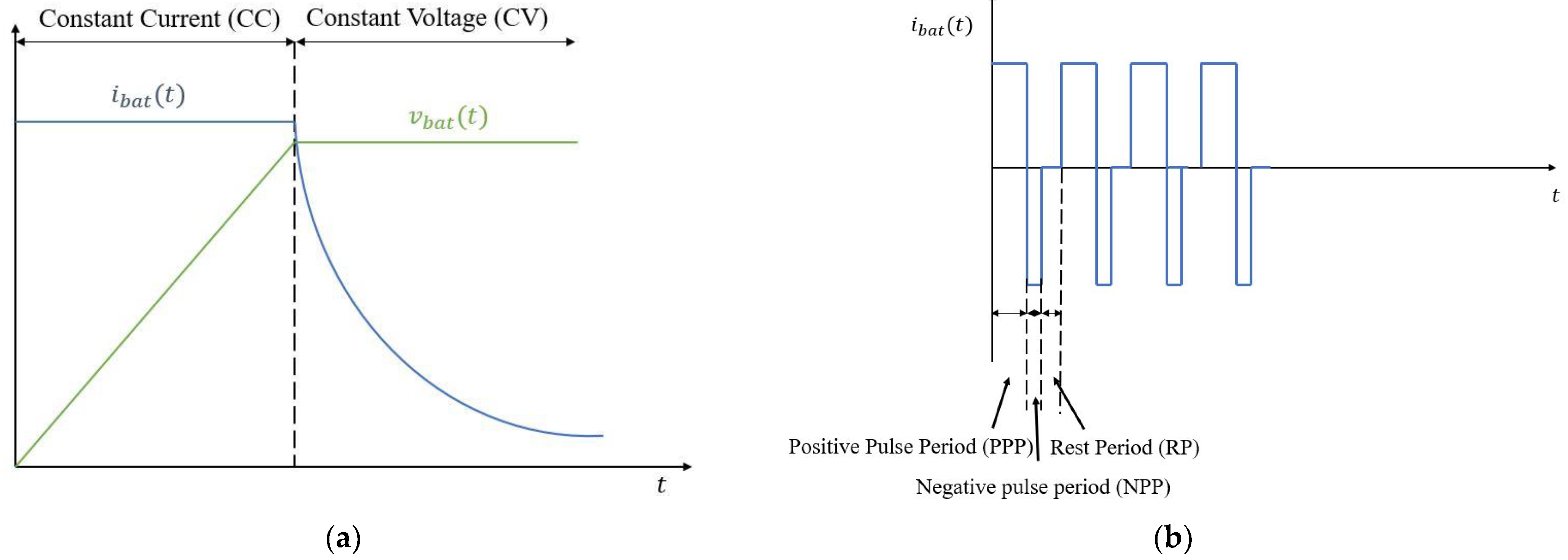
In addition to the choice of power electronic converter, an appropriate charging control technique is imperative to ensure battery and user safety. Constant current-constant voltage (CC-CV) remains the most popular control scheme for LEV charging converters, mainly because of its ease in implementation. In this process, a constant current is applied for a finite time, until the battery voltage reaches at least near its nominal value. Following this, the control transitions to constant voltage, where the charging current decays to zero, with the voltage held constant. The variation of voltage and current according to this control scheme is shown in Figure 23.
However, the CC-CV control approach has certain limitations such as long charging times, thermal deterioration of battery and low efficiency [63]. Hence, this approach does not lend itself to fast charging applications, which require higher currents.
To overcome the limitations of the CC-CV, a new charging control approach known as reflex charging is proposed in recent publications [63,72,125,126]. This approach allows for higher charging currents to be injected in pulses. The battery charging current profile also contains negative pulse periods and rest periods to momentarily reverse the charging process and neutralize the electrolyte, respectively. The negative period helps in reducing bubbles, which would otherwise increase battery resistance [72]. Thus, reflex charging allows for an improved thermal profile of the battery. However, one limitation of this control technique is the reduction in average charging current due to the negative pulse period. This can be counteracted by appropriate selection of pulse width and current amplitude. The variation of charging current according to this control scheme is shown in Figure 23.
Furthermore, considering the significance of battery thermal performance from a safety standpoint, special emphasis should be placed on control techniques by considering the temperature. In this regard, a constant temperature (CT) control, which adjusts the charging current based on the ambient temperature, may be used. Through this process, one can carry out the charging process within a limited temperature band. The authors of [127] presented a charging control technique which dynamically sets the charging current according to the battery temperature. This work achieved a 20% lower cell temperature rise for a given total charging time, thus validating this control approach. A summary of discussed control techniques is shown in Table 5.

6.6. Standardization of LEV Charging

A significant challenge in the expansion of LEV charging stations is the lack of standardization. In recent years, numerous standards have been enforced for conventional EVs [13,128] by organizations such as IEC (IEC 61851) [129] and SAE (J1772) [130], which deal with AC and DC charging. Furthermore, standards are also in place for the type of connectors used [81]. Although efforts have been made to standardize charging stations for LEVs such as BEVC-AC001/DC001 [131] and Type 3 A [81] for connectors, efforts must be made by LEV manufacturers to ensure compatibility with these standards. Battery swapping stations must also be standardised to ensure cross-compatibility.
Another related concern is the lack of standards for LEV batteries. LEV batteries can range anywhere from 48 V to 72 V, and furthermore, they may also lack an active cooling mechanism [3]. This can potentially cause safety hazards. Hence, standardization of LEV batteries and charging features is a main priority for manufacturers to increase LEV adoption in the future.

6.7. Electrical Insulation Considerations

Another aspect that needs special attention in conductive LEV charging systems is the electrical insulation. Dielectric and electrical insulation considerations have been discussed at length for smart grid systems [132], where increase in EV penetration is mentioned as a contributing factor to changing load patterns—ultimately calling for advanced insulation monitoring techniques. The effect of DC-based EV fast charging stations on distribution transformers was explored in [13]. In this work, the impact of EV penetration level was evaluated using transformer insulation life and it was found that there was an increase in transformer ageing with increasing EV penetration.
Measures must be taken to monitor insulation conditions in LEV charger systems, which can help evaluate subsequent equipment life. Such measures are especially beneficial for isolated topologies. High frequency transformers in isolated topologies normally require insulation material between the core and the conductors [133], which can potentially become impacted due to component ageing. The same goes for insulation and dielectrics associated with passive components, which can also be subject to thermal effects [134]. Furthermore, insulation in cables and battery-side is also prone to wear and tear due to chafing and environmental factors, which can lead to safety concerns—thus necessitating the use of insulation monitoring techniques. One such monitoring technique was described in [49] for non-isolated topologies, which used a voltage divider along with detector circuits for this purpose.
Hence, a future possible research avenue can deal with insulation ageing in charger circuit components and monitoring methods, thus providing a perspective on remaining lifetime and improving safety.

7. Conclusions

In this review study, recent trends in DC-DC converter implementations for LEV charging were chronicled—ranging from on-board chargers to off-board chargers. From these trends, we have observed that on-board charging technology has reached a high level of maturity in recent years. Off-board chargers were also discussed in this work, as an alternative to on-board charging. Although off-board charging has not reached same the level of maturity as that of on-board, the technology is increasing in interest among researchers—so much so that their suitability for renewable energy integration is being heavily evaluated. Furthermore, the segregation of DC-DC converters into isolated and non-isolated topologies was also discussed. It was observed that while isolated converters can inherently support soft-switching and are beneficial from a safety point of view, they suffer from setbacks such as voltage spikes during switching and relatively high component count. In contrast, non-isolated converters are also an option for LEV charging due to their relatively simple and compact design, and they can be explored further. A gap that needs addressing is to arrive at a balance between circuit and control complexity, and converter performance parameters. Another gap in research that needs to be investigated is the unlocking of potential for vehicle to grid (V2G) capability.
Additionally, this review discusses issues and some emerging techniques that can be used to augment LEV charging:
  • Wireless charging techniques, their optimization and safety aspects.
  • Fast charging through high current DC-DC converters, and battery swapping.
  • Integration of renewable energy sources such as solar PV into charging system, ensuing challenges and how to overcome them.
  • Use of superior wide band-gap semiconductor switches for implementing LEV fast chargers, and barriers in their adoption.
  • Advanced charging techniques such as reflex charging and constant temperature control.
  • Compatibility of LEVs with standardized charging stations and battery swapping stations.
  • Considerations with respect to electrical insulation requirements and necessity for insulation monitoring.

Author Contributions

Conceptualization, M.F.A., S.R.S.R. and M.N.A.; Formal analysis, M.F.A., S.R.S.R. and N.A.R.; Funding acquisition, M.N.A. and E.A.B.; Methodology, M.F.A., S.R.S.R. and N.A.R.; Project administration, S.R.S.R., S.R.S.R. and E.A.B.; Supervision, S.R.S.R. and N.A.R.; Writing—original draft, M.F.A.; Writing—review and editing, M.F.A., S.R.S.R. and E.A.B. All authors have read and agreed to the published version of the manuscript.

Funding

The work is supported by the Ministry of Higher Education Malaysia via Fundamental Research Grant Scheme (FRGS/1/2020/TK0/UM/02/41). The authors also thank the technical and financial assistance of UM Power Energy Dedicated Advanced Centre (UMPEDAC) and the Higher Institution Centre of Excellence (HICoE) Program Research Grant, UMPEDAC—2020 (MOHE HICOE—UMPEDAC), Ministry of Education Malaysia, IF006-2021, RU002-202s1, University of Malaya.

Institutional Review Board Statement

Not applicable.

Informed Consent Statement

Not applicable.

Acknowledgments

The authors thank the technical and financial assistance of UM Power Energy Dedicated Advanced Centre (UMPEDAC) and the Higher Institution Centre of Excellence (HICoE) Program Research Grant, UMPEDAC—2020 (MOHE HICOE—UMPEDAC), Ministry of Education Malaysia, IF006-2021, RU002-2021, University of Malaya.

Conflicts of Interest

The authors declare no conflict of interest.

References

  1. International Energy Agency. Global EV Outlook 2022; IEA: Paris, France, 2022. [Google Scholar]
  2. Will, S.; Luger-Bazinger, C.; Schmitt, M.; Zankl, C. Towards the future of sustainable mobility: Results from a European survey on (electric) powered-two wheelers. Sustainability 2021, 13, 7151. [Google Scholar] [CrossRef]
  3. Sasidharan, C.; Tyagi, B.; Rajah, V. Light electric vehicles and their charging aspects. In Electric Vehicles; Springer: Singapore, 2021; pp. 33–51. [Google Scholar]
  4. Mouli, G.R.C.; van Duijsen, P.; Grazian, F.; Jamodkar, A.; Bauer, P.; Isabella, O. Sustainable e-bike charging station that enables ac, dc andwireless charging from solar energy. Energies 2020, 13, 3549. [Google Scholar] [CrossRef]
  5. Ather Energy. Available online: https://www.atherenergy.com/ (accessed on 15 October 2022).
  6. Hero Electric Bikes and Scooters. Available online: https://heroelectric.in/bikes/ (accessed on 15 October 2022).
  7. Okinawa Electric PraisePro. Available online: https://okinawascooters.com/products/praisepro/# (accessed on 15 October 2022).
  8. Mahindra Treo. Available online: https://www.mahindraelectric.com/vehicles/treo-electric-auto/ (accessed on 15 October 2022).
  9. Piaggio Ape E-City. Available online: https://piaggio-cv.co.in/ape-e-city/ (accessed on 15 October 2022).
  10. Terra Motors Y4A. Available online: https://terramotors.in/y4a (accessed on 15 October 2022).
  11. Vaideeswaran, V.; Hariharan, S.; Jayadarshan, N.S.; Pragadheesan, K. Review on Electric Two Wheeler Chargers and International Standards. In Proceedings of the 2021 Innovations in Power and Advanced Computing Technologies (i-PACT), Kuala Lumpur, Malaysia, 27–29 November 2021; pp. 1–5. [Google Scholar]
  12. Rafi, M.A.H.; Bauman, J. A Comprehensive Review of DC Fast-Charging Stations with Energy Storage: Architectures, Power Converters, and Analysis. IEEE Trans. Transp. Electrif. 2021, 7, 345–368. [Google Scholar] [CrossRef]
  13. Yilmaz, M.; Krein, P.T. Review of Battery Charger Topologies, Charging Power Levels, and Infrastructure for Plug-In Electric and Hybrid Vehicles. IEEE Trans. Power Electron. 2013, 28, 2151–2169. [Google Scholar] [CrossRef]
  14. IEEE Power and Energy Society. IEEE Recommended Practice and Requirements for Harmonic Control in Electric Power Systems. IEEE Std. 2014, 2014, 519–2014. [Google Scholar]
  15. International Electrotechnical Commission. Electromagnetic Compatibility (EMC)—Part 3-2: Limits—Limits for Harmonic Current Emissions (Equipment Input Current ≤16 A per Phase); IEC 61000-3-2:2018; International Electrotechnical Commission (IEC): Geneva, Switzerland, 2018. [Google Scholar]
  16. Lin, B.-R. Analysis and Implementation of a Frequency Control DC–DC Converter for Light Electric Vehicle Applications. Electronics 2021, 10, 1623. [Google Scholar] [CrossRef]
  17. Gupta, J.; Singh, B. Single-Stage Isolated Bridgeless Charger for Light Electric Vehicle with Improved Power Quality. IEEE Trans. Ind. Appl. 2022, 58, 6357–6367. [Google Scholar] [CrossRef]
  18. Gupta, J.; Singh, B. Bridgeless Isolated Positive Output Luo Converter Based High Power Factor Single Stage Charging Solution for Light Electric Vehicles. IEEE Trans. Ind. Appl. 2022, 58, 732–741. [Google Scholar] [CrossRef]
  19. Chaudhary, C.; Mishra, S.; Nangia, U. A Bridgeless Isolated Zeta Converter for Battery Charging Aided with Solar Photovoltaic System. In Proceedings of the 2021 International Conference on Smart Generation Computing, Communication and Networking (SMART GENCON), Pune, India, 29–30 October 2021; pp. 1–6. [Google Scholar] [CrossRef]
  20. Shukla, T.; Kalla, U.K. A Modified Non-bridged Cuk Converter based Electric Vehicle Charger with Reduced Components Count. In Proceedings of the 2021 IEEE 2nd International Conference on Smart Technologies for Power, Energy and Control (STPEC), Bilaspur, India, 19–22 December 2021; pp. 1–6. [Google Scholar] [CrossRef]
  21. Pandey, R.; Singh, B. A Cuk Converter and Resonant LLC Converter Based E-Bike Charger for Wide Output Voltage Variations. IEEE Trans. Ind. Appl. 2021, 57, 2682–2691. [Google Scholar] [CrossRef]
  22. Kim, D.-H.; Kim, M.-S.; Nengroo, S.H.; Kim, C.-H.; Kim, H.-J. LLC Resonant Converter for LEV (Light Electric Vehicle) Fast Chargers. Electronics 2019, 8, 362. [Google Scholar] [CrossRef] [Green Version]
  23. Dixit, A.; Gangavarapu, S.; Rathore, A.K. High-Efficiency Discontinuous Current-Mode Power Factor Correction-Based Plug-In Battery Charger for Local e-Transportation. IEEE Trans. Transp. Electrif. 2021, 7, 1134–1145. [Google Scholar] [CrossRef]
  24. Gumera, X.D.; Caberos, A.; Huang, S.-C. Design and Implementation of a High Efficiency Cost Effective EV Charger Using LLC Resonant Converter. In Proceedings of the 2017 Asian Conference on Energy, Power and Transportation Electrification (ACEPT), Singapore, 24–26 October 2017; pp. 1–6. [Google Scholar] [CrossRef]
  25. Sayed, S.S.; Massoud, A.M. Review on State-of-the-Art Unidirectional Non-Isolated Power Factor Correction Converters for Short-/Long-Distance Electric Vehicles. IEEE Access 2022, 10, 11308–11340. [Google Scholar] [CrossRef]
  26. Faridpak, B.; Farrokhifar, M.; Nasiri, M.; Alahyari, A.; Sadoogi, N. Developing a super-lift luo-converter with integration of buck converters for electric vehicle applications. CSEE J. Power Energy Syst. 2020, 7, 811–820. [Google Scholar] [CrossRef]
  27. Jazi, H.N.; Goudarzian, A.; Pourbagher, R.; Derakhshandeh, S.Y. PI and PWM Sliding Mode Control of POESLL Converter. IEEE Trans. Aerosp. Electron. Syst. 2017, 53, 2167–2177. [Google Scholar] [CrossRef]
  28. Kouzou, A. Power Factor Correction Circuits. In Power Electronics Handbook; Elsevier: Amsterdam, The Netherlands, 2018; pp. 529–569. [Google Scholar] [CrossRef]
  29. Jiang, L.; Wan, J.; Li, Y.; Huang, C.; Liu, F.; Wang, H.; Sun, Y.; Cao, Y. A New Push-Pull DC/DC Converter Topology With Complementary Active Clamped. IEEE Trans. Ind. Electron. 2022, 69, 6445–6449. [Google Scholar] [CrossRef]
  30. Moghaddam, A.F.; van den Bossche, A. Forward Converter Current Fed Equalizer for Lithium Based Batteries in Ultralight Electrical Vehicles. Electronics 2019, 8, 408. [Google Scholar] [CrossRef] [Green Version]
  31. Lee, H.-S.; Kang, B.; Kim, W.-S.; Yoon, S.-J. Reduction of input voltage/current ripples of boost half-bridge DC-DC converter for photovoltaic micro-inverter. Sol. Energy 2019, 188, 1084–1101. [Google Scholar] [CrossRef]
  32. Jou, H.-L.; Huang, J.-J.; Wu, J.-C.; Wu, K.-D. Novel Isolated Multilevel DC–DC Power Converter. IEEE Trans. Power Electron. 2016, 31, 2690–2694. [Google Scholar] [CrossRef]
  33. Gupta, J.; Kushwaha, R.; Singh, B. Improved Power Quality Transformerless Single-Stage Bridgeless Converter Based Charger for Light Electric Vehicles. IEEE Trans. Power Electron. 2021, 36, 7716–7724. [Google Scholar] [CrossRef]
  34. Shukla, T.; Kalla, U.K. A Single-Stage positive Cuk Converter based Charging System for Light Electric Vehicle Applications. In Proceedings of the 2021 IEEE 2nd International Conference on Smart Technologies for Power, Energy and Control (STPEC), Bilaspur, India, 19–22 December 2021; pp. 1–6. [Google Scholar] [CrossRef]
  35. Singh, B.; Gupta, J. Improved Power Quality On-Board Charging Solution for Light Electric Vehicles. In Proceedings of the 2021 IEEE Transportation Electrification Conference & Expo (ITEC), Chicago, IL, USA, 21–25 June 2021; pp. 462–467. [Google Scholar] [CrossRef]
  36. Gupta, J.; Kushwaha, R.; Singh, B. An Isolated Improved Power Quality Battery Charger for a Light Electric Vehicle. In Proceedings of the 2020 IEEE International Conference on Power Electronics, Smart Grid and Renewable Energy (PESGRE2020), Cochin, India, 2–4 January 2020; pp. 1–6. [Google Scholar] [CrossRef]
  37. Kushwaha, R.; Singh, B. Power Factor Correction in EV Charger with Bridgeless Zeta-SEPIC Converter. In Proceedings of the 2019 IEEE Energy Conversion Congress and Exposition (ECCE), Baltimore, MD, USA, 29 September–3 October 2019; pp. 121–128. [Google Scholar] [CrossRef]
  38. Kushwaha, R.; Singh, B. Power Factor Improvement in Modified Bridgeless Landsman Converter Fed EV Battery Charger. IEEE Trans. Veh. Technol. 2019, 68, 3325–3336. [Google Scholar] [CrossRef]
  39. Kushwaha, R.; Singh, B. Interleaved Landsman Converter Fed EV Battery Charger with Power Factor Correction. IEEE Trans. Ind. Appl. 2020, 56, 4179–4192. [Google Scholar] [CrossRef]
  40. Sankar, U.A.; Mallik, A.; Khaligh, A. Duty compensated reduced harmonic control for a single-phase H-bridge PFC converter. In Proceedings of the 2018 IEEE Applied Power Electronics Conference and Exposition (APEC), San Antonio, TX, USA, 4–8 March 2018; pp. 1996–2000. [Google Scholar] [CrossRef]
  41. Chaurasiya, S.; Singh, B. A High-Power Density Portable Charger for E-Mopeds and E-Rickshaw. In Proceedings of the 2021 IEEE 4th International Conference on Computing, Power and Communication Technologies (GUCON), Kuala Lumpur, Malaysia, 24–26 September 2021; pp. 1–7. [Google Scholar] [CrossRef]
  42. He, P.; Khaligh, A. Comprehensive Analyses and Comparison of 1 kW Isolated DC–DC Converters for Bidirectional EV Charging Systems. IEEE Trans. Transp. Electrif. 2017, 3, 147–156. [Google Scholar] [CrossRef]
  43. Shreya, K.; Srivastava, H.; Kumar, P.; Ramanathan, G.; Madhavan, P.; Bharatiraja, C. CUK converter fed resonant LLC converter based electric bike fast charger for efficient cc/cv charging solution. J. Appl. Sci. Eng. 2021, 24, 331–338. [Google Scholar] [CrossRef]
  44. Syah, M.N.; Firmansyah, E.; Utomo, D.R. Interleaved Bidirectional DC-DC Converter Operation Strategies and Problem Challenges: An Overview. In Proceedings of the 2022 IEEE International Conference in Power Engineering Application (ICPEA), Shah Alam, Malaysia, 7–8 March 2022; pp. 1–6. [Google Scholar] [CrossRef]
  45. Sharma, U.; Singh, B. A Multistep Bidirectional Onboard Charger for Light Electric Vehicles Using Interleaved Luo Converter. In Proceedings of the 2021 International Conference on Sustainable Energy and Future Electric Transportation (SEFET), Hyderabad, India, 21–23 January 2021; pp. 1–5. [Google Scholar] [CrossRef]
  46. Sharma, U.; Singh, B. A Bidirectional Onboard Charging System for E-Rickshaw Using Interleaved SEPIC Converter. In Proceedings of the 2020 IEEE 17th India Council International Conference (INDICON), New Delhi, India, 10–13 December 2020; pp. 1–5. [Google Scholar] [CrossRef]
  47. Sharma, U.; Singh, B. An Onboard Bidirectional Charger for Light Electric Vehicles Using Interleaved ZETA Converter. In Proceedings of the 2020 International Conference on Power, Instrumentation, Control and Computing (PICC), Thrissur, India, 17–19 December 2020; pp. 1–6. [Google Scholar] [CrossRef]
  48. Lai, C.-M. Development of a Novel Bidirectional DC/DC Converter Topology with High Voltage Conversion Ratio for Electric Vehicles and DC-Microgrids. Energies 2016, 9, 410. [Google Scholar] [CrossRef] [Green Version]
  49. Wang, J.; Zhang, Y.; Elshaer, M.; Perdikakis, W.; Yao, C.; Zou, K.; Xu, Z.; Chen, C. Nonisolated Electric Vehicle Chargers: Their Current Status and Future Challenges. IEEE Electrif. Mag. 2021, 9, 23–33. [Google Scholar] [CrossRef]
  50. Sharma, U.; Singh, B. A Bidirectional Charger for Light Electric Vehicle Using Coupled-Inductor based High Gain SEPIC Converter. In Proceedings of the 2021 IEEE 2nd International Conference on Smart Technologies for Power, Energy and Control (STPEC), Bilaspur, India, 19–22 December 2021; pp. 1–6. [Google Scholar] [CrossRef]
  51. Gupta, J.; Singh, B. A Switched Capacitor-Coupled Inductor Based High Gain Buck Converter with Power Factor Pre-regulator for LEVs Charging Application. In Proceedings of the 2021 IEEE 4th International Conference on Computing, Power and Communication Technologies (GUCON), Kuala Lumpur, Malaysia, 24–26 September 2021; pp. 1–6. [Google Scholar] [CrossRef]
  52. Blinov, A.; Verbytskyi, I.; Zinchenko, D.; Vinnikov, D.; Galkin, I. Modular Battery Charger for Light Electric Vehicles. Energies 2020, 13, 774. [Google Scholar] [CrossRef] [Green Version]
  53. Gupta, J.; Kushwaha, R.; Singh, B.; Khadkikar, V. Improved Power Quality Charging System Based on High Step-Down Gain Bridgeless SEPIC APFC for Light Electric Vehicles. IEEE Trans. Ind. Appl. 2022, 58, 423–434. [Google Scholar] [CrossRef]
  54. Ramanathan, G.; Bharatiraja, C. Design of mono stage bridgeless converter for light electric vehicles charging. Mater. Today Proc. 2022, 52, 1530–1536. [Google Scholar] [CrossRef]
  55. Hussein, B.; Alsalemi, A.; Ben-Brahim, L. High-Gain Non-isolated Single-Switch DC-DC Converters in Power Factor Correction Rectifiers: A Performance Assessment. In Proceedings of the 2022 3rd International Conference on Smart Grid and Renewable Energy (SGRE), Doha, Qatar, 20–22 March 2022; pp. 1–6. [Google Scholar] [CrossRef]
  56. Sharma, U.; Singh, B. A Non-isolated Onboard Charger for Electric Vehicle. In Proceedings of the 2021 IEEE Transportation Electrification Conference & Expo (ITEC), Chicago, IL, USA, 21–25 June 2021; pp. 446–451. [Google Scholar] [CrossRef]
  57. Kumar, A.D.; Gupta, J.; Singh, B. A Single-Stage Charger for LEV Application based on Quadratic Buck-Boost Converter Topology. In Proceedings of the 2022 IEEE IAS Global Conference on Emerging Technologies (GlobConET), Arad, Romania, 20–22 May 2022; pp. 321–326. [Google Scholar] [CrossRef]
  58. Yuan, J.; Dorn-Gomba, L.; Callegaro, A.D.; Reimers, J.; Emadi, A. A Review of Bidirectional On-Board Chargers for Electric Vehicles. IEEE Access 2021, 9, 51501–51518. [Google Scholar] [CrossRef]
  59. LiveWire. Available online: https://www.livewire.com/livewire-one-electric-motorcycle#livewire-one-specs (accessed on 15 October 2022).
  60. Mouli, G.R.C.; Schijffelen, J.; van den Heuvel, M.; Kardolus, M.; Bauer, P. A 10 kW Solar-Powered Bidirectional EV Charger Compatible with Chademo and COMBO. IEEE Trans. Power Electron. 2019, 34, 1082–1098. [Google Scholar] [CrossRef] [Green Version]
  61. Çalışkan, E.; Ustun, O. Smart Efficiency Tracking for Novel Switch—LLC Converter for Battery Charging Applications. Energies 2022, 15, 1861. [Google Scholar] [CrossRef]
  62. Askarian, I.; Palevani, M.; Knight, A. A new method to achieve ZVS for DC-DC Dual Active Bridge (DAB) converters used between electric vehicles and DC micro-grids. In Proceedings of the 2017 IEEE Second International Conference on DC Microgrids (ICDCM), Nuremburg, Germany, 27–29 June 2017; pp. 102–105. [Google Scholar] [CrossRef]
  63. ElMenshawy, M.; Massoud, A. Development of Modular DC-DC Converters for Low-Speed Electric Vehicles Fast Chargers. Alex. Eng. J. 2021, 60, 1067–1083. [Google Scholar] [CrossRef]
  64. Ghosh, S.; Singh, B. A Reconfigurable Dual Active Bridge Converter with Wide ZVS Range for Charging of Electric Vehicles. In Proceedings of the 2020 IEEE International Conference on Power Electronics, Drives and Energy Systems (PEDES), Jaipur, India, 16–19 December 2020; pp. 1–6. [Google Scholar] [CrossRef]
  65. Piasecki, S.; Zaleski, J.; Jasinski, M.; Bachman, S.; Turzyński, M. Analysis of AC/DC/DC Converter Modules for Direct Current Fast-Charging Applications. Energies 2021, 14, 6369. [Google Scholar] [CrossRef]
  66. Qin, Z.; Shen, Z.; Blaabjerg, F.; Bauer, P. Transformer Current Ringing in Dual Active Bridge Converters. IEEE Trans. Ind. Electron. 2021, 68, 12130–12140. [Google Scholar] [CrossRef]
  67. Singh, A.; Shaha, S.S.; Nikhil, P.G.; Sekhar, Y.R.; Saboor, S.; Ghosh, A. Design and Analysis of a Solar-Powered Electric Vehicle Charging Station for Indian Cities. World Electr. Veh. J. 2021, 12, 132. [Google Scholar] [CrossRef]
  68. Singh, K.; Mishra, A.K.; Singh, B.; Sahay, K. Solar powered battery charging scheme for light electric vehicles (LEVs). Int. J. Emerg. Electr. Power Syst. 2021, 22, 101–111. [Google Scholar] [CrossRef]
  69. Atawi, I.E.; Hendawi, E.; Zaid, S.A. Analysis and Design of a Standalone Electric Vehicle Charging Station Supplied by Photovoltaic Energy. Processes 2021, 9, 1246. [Google Scholar] [CrossRef]
  70. Nachinarkiniyan, S.; Subramanian, K. Off-board electric vehicle battery charger using PV array. IET Electr. Syst. Transp. 2020, 10, 291–300. [Google Scholar] [CrossRef]
  71. Alatai, S.; Salem, M.; Alhamrouni, I.; Ishak, D.; Bughneda, A.; Kamarol, M. Design Methodology and Analysis of Five-Level LLC Resonant Converter for Battery Chargers. Sustainability 2022, 14, 8255. [Google Scholar] [CrossRef]
  72. Lai, C.-M.; Li, Y.-H.; Cheng, Y.-H.; Teh, J. A High-Gain Reflex-Based Bidirectional DC Charger with Efficient Energy Recycling for Low-Voltage Battery Charging-Discharging Power Control. Energies 2018, 11, 623. [Google Scholar] [CrossRef]
  73. Hosseini, S.H.; Ghazi, R.; Heydari-Doostabad, H. An Extendable Quadratic Bidirectional DC–DC Converter for V2G and G2V Applications. IEEE Trans. Ind. Electron. 2021, 68, 4859–4869. [Google Scholar] [CrossRef]
  74. Kurs, A.; Karalis, A.; Moffatt, R.; Joannopoulos, J.D.; Fisher, P.; Soljačić, M. Wireless Power Transfer via Strongly Coupled Magnetic Resonances. Science 2007, 317, 83–86. [Google Scholar] [CrossRef] [PubMed] [Green Version]
  75. Beh, H.Z.Z.; Covic, G.A.; Boys, J.T. Wireless Fleet Charging System for Electric Bicycles. IEEE J. Emerg. Sel. Top. Power Electron. 2015, 3, 75–86. [Google Scholar] [CrossRef]
  76. Jiang, W.; Xu, S.; Li, N.; Lin, Z.; Williams, B.W. Wireless power charger for light electric vehicles. In Proceedings of the 2015 IEEE 11th International Conference on Power Electronics and Drive Systems, Sydney, Australia, 9–12 June 2015; pp. 562–566. [Google Scholar] [CrossRef]
  77. Joseph, P.K.; Elangovan, D.; Arunkumar, G. Linear control of wireless charging for electric bicycles. Appl. Energy 2019, 255, 113898. [Google Scholar] [CrossRef]
  78. Xiong, M.; Liu, D.; Zhang, Z.; Li, W. Design and effect analysis of wireless energy transmission device for electric vehicle. In Proceedings of the 2021 International Conference on Information Control, Electrical Engineering and Rail Transit (ICEERT), Lanzhou, China, 30 October 2021–1 November 2021; pp. 91–94. [Google Scholar] [CrossRef]
  79. Hvarchilkov, D.S.; Dimitrov, V.V.; Arnaudov, D.D. Resonant Converter for Inductive Charging of Light Electric Vehicles. In Proceedings of the 2018 IEEE XXVII International Scientific Conference Electronics-ET, Sozopol, Bulgaria, 3–15 September 2018; pp. 1–4. [Google Scholar] [CrossRef]
  80. Joseph, P.K.; Elangovan, D. A review on renewable energy powered wireless power transmission techniques for light electric vehicle charging applications. J. Energy Storage 2018, 16, 145–155. [Google Scholar] [CrossRef]
  81. Ashfaq, M.; Butt, O.; Selvaraj, J.; Rahim, N. Assessment of electric vehicle charging infrastructure and its impact on the electric grid: A review. Int. J. Green Energy 2021, 18, 657–686. [Google Scholar] [CrossRef]
  82. Trivino-Cabrera, A.; Gonzalez-Gonzalez, J.M.; Aguado, J.A. Design and Implementation of a Cost-Effective Wireless Charger for an Electric Bicycle. IEEE Access 2021, 9, 85277–85288. [Google Scholar] [CrossRef]
  83. Chen, Y.; Yang, N.; Yang, B.; Dai, R.; He, Z.; Mai, R.; Gao, S. Two-/three-coil hybrid topology and coil design for WPT system charging electric bicycles. IET Power Electron. 2019, 12, 2501–2512. [Google Scholar] [CrossRef]
  84. Liu, S.; Li, X.; Yang, L. Three-coil structure-based WPT system design for electric bike CC and CV charging without communication. IET Electr. Power Appl. 2019, 13, 1318–1327. [Google Scholar] [CrossRef]
  85. Shevchenko, V.; Pakhaliuk, B.; Zakis, J.; Veligorskyi, O.; Luszcz, J.; Husev, O.; Lytvyn, O.; Matiushkin, O. Closed-Loop Control System Design for Wireless Charging of Low-Voltage EV Batteries with Time-Delay Constraints. Energies 2021, 14, 3934. [Google Scholar] [CrossRef]
  86. Liu, S.; Zhao, X.; Wu, Y.; Zhou, L.; Li, Y.; Mai, R.; He, Z. Efficiency Improvement of Dual-Receiver WPT Systems Based on Partial Power Processing Control. IEEE Trans. Power Electron. 2022, 37, 7456–7469. [Google Scholar] [CrossRef]
  87. Liorni, I.; Bottauscio, O.; Guilizzoni, R.; Ankarson, P.; Bruna, J.; Fallahi, A.; Harmon, S.; Zucca, M. Assessment of Exposure to Electric Vehicle Inductive Power Transfer Systems: Experimental Measurements and Numerical Dosimetry. Sustainability 2020, 12, 4573. [Google Scholar] [CrossRef]
  88. Vaka, R.; Keshri, R.K. Evaluation and selection of shielding methods for wireless charging of e-rickshaw. Electr. Eng. 2020, 102, 1005–1019. [Google Scholar] [CrossRef]
  89. Naradhipa, A.M.; Kim, S.; Choi, S.; Jung, J.-H.; Joo, J.-H.; Ahn, D.-S.; Lee, Y.-S.; Yeo, I.-Y. A Compact 700kHz 1.8kW GaN-based Transistor Low Voltage High Current DC-DC Converter for xEV using Planar Matrix Transformer. In Proceedings of the 2019 10th International Conference on Power Electronics and ECCE Asia (ICPE 2019-ECCE Asia), Busan, Korea, 27–30 May 2019; pp. 1–6. [Google Scholar] [CrossRef]
  90. Kim, B.; Kim, K.; Choi, S. A 800V/14V Soft-switched Converter with Low-Voltage Rating of Switch for xEV applications. In Proceedings of the 2018 International Power Electronics Conference (IPEC-Niigata 2018-ECCE Asia), Niigata, Japan, 20–24 May 2018; pp. 256–260. [Google Scholar] [CrossRef]
  91. Hong, D.-Y.; Kong, S.-J.; Lee, J.-Y. Design of a 5.6 kW EV low-voltage DC/DC converter based on full-bridge converter with input series output parallel structure. J. Power Electron. 2022, 22, 395–405. [Google Scholar] [CrossRef]
  92. Zheng, Y.; Li, S.; Smedley, K.M. Nonisolated High Step-Down Converter with ZVS and Low Current Ripples. IEEE Trans. Ind. Electron. 2019, 66, 1068–1079. [Google Scholar] [CrossRef]
  93. Khalili, S.; Farzanehfard, H.; Esteki, M. High step-down dc–dc converter with low voltage stress and wide soft-switching range. IET Power Electron. 2020, 13, 3001–3008. [Google Scholar] [CrossRef]
  94. Fatahi, S.A.S.; Esteki, M.; Farzanehfard, H. A Soft Switching Interleaved High Step-down Converter with Low Voltage Stress. In Proceedings of the 2021 12th Power Electronics, Drive Systems, and Technologies Conference (PEDSTC), Tabriz, Iran, 2–4 February 2021; pp. 1–6. [Google Scholar] [CrossRef]
  95. Amiri, M.; Farzanehfard, H. An Interleaved Nonisolated ZVS Ultrahigh Step-Down DC–DC Converter with Low Voltage Stress. IEEE Trans. Ind. Electron. 2019, 66, 7663–7671. [Google Scholar] [CrossRef]
  96. Mayer, R.; el Kattel, M.B.; Oliveira, S.V.G. Multiphase Interleaved Bidirectional DC/DC Converter with Coupled Inductor for Electrified-Vehicle Applications. IEEE Trans. Power Electron. 2021, 36, 2533–2547. [Google Scholar] [CrossRef]
  97. Moradisizkoohi, H.; Elsayad, N.; Mohammed, O.A. A Voltage-Quadrupler Interleaved Bidirectional DC–DC Converter with Intrinsic Equal Current Sharing Characteristic for Electric Vehicles. IEEE Trans. Ind. Electron. 2021, 68, 1803–1813. [Google Scholar] [CrossRef]
  98. Revankar, S.R.; Kalkhambkar, V.N. Grid integration of battery swapping station: A review. J. Energy Storage 2021, 41, 102937. [Google Scholar] [CrossRef]
  99. Esmaeili, S.; Anvari-Moghaddam, A.; Jadid, S. Optimal Operation Scheduling of a Microgrid Incorporating Battery Swapping Stations. IEEE Trans. Power Syst. 2019, 34, 5063–5072. [Google Scholar] [CrossRef]
  100. Wang, Y.; Ding, W.; Huang, L.; Wei, Z.; Liu, H.; Stankovic, J.A. Toward Urban Electric Taxi Systems in Smart Cities: The Battery Swapping Challenge. IEEE Trans. Veh. Technol. 2018, 67, 1946–1960. [Google Scholar] [CrossRef]
  101. Arif, S.M.; Lie, T.T.; Seet, B.C.; Ayyadi, S.; Jensen, K. Review of Electric Vehicle Technologies, Charging Methods, Standards and Optimization Techniques. Electronics 2021, 10, 1910. [Google Scholar] [CrossRef]
  102. Andwari, A.M.; Pesiridis, A.; Rajoo, S.; Martinez-Botas, R.; Esfahanian, V. A review of Battery Electric Vehicle technology and readiness levels. Renew. Sustain. Energy Rev. 2017, 78, 414–430. [Google Scholar] [CrossRef]
  103. Kumar, G.; Singh, B. Cuk Converter Derived Dual-Input Charger for PV Panel Mounted Light Electric Vehicles. In Proceedings of the 2021 IEEE 6th International Conference on Computing, Communication and Automation (ICCCA), Arad, Romania, 17–19 December 2021; pp. 70–76. [Google Scholar] [CrossRef]
  104. Singh, A.K.; Chinmaya, K.A.; Badoni, M. Solar PV and Grid Based Isolated Converter for Plug-in Electric Vehicles. IET Power Electron. 2019, 12, 3707–3715. [Google Scholar] [CrossRef]
  105. Singh, A.K.; Badoni, M.; Tatte, Y.N. A Multifunctional Solar PV and Grid Based On-Board Converter for Electric Vehicles. IEEE Trans. Veh. Technol. 2020, 69, 3717–3727. [Google Scholar] [CrossRef]
  106. Gupta, J.; Singh, B.; Kushwaha, R. A Rooftop Solar PV Assisted On-Board Enhanced Power Quality Charging System for E-Rickshaw. In Proceedings of the 2020 International Conference on Power, Instrumentation, Control and Computing (PICC), Thrissur, India, 17–19 December 2020; pp. 1–6. [Google Scholar] [CrossRef]
  107. Kumar, D.; Saxena, A.R. A battery integrated three-port bidirectional charger/discharger for light electric vehicles with G2V and V2G power flow capability. Int. J. Circuit Theory Appl. 2021, 49, 2909–2934. [Google Scholar] [CrossRef]
  108. Singh, K.; Mishra, A.K.; Singh, B.; Sahay, K. Cost-Effective Solar Powered Battery Charging System for Light Electric Vehicles (LEVs). In Proceedings of the 2019 International Conference on Computing, Power and Communication Technologies, GUCON 2019, NCR, New Delhi, India, 27–28 September 2019. [Google Scholar]
  109. Ashique, R.H.; Salam, Z.; Aziz, M.J.b.A.; Bhatti, A.R. Integrated photovoltaic-grid dc fast charging system for electric vehicle: A review of the architecture and control. Renew. Sustain. Energy Rev. 2017, 69, 1243–1257. [Google Scholar] [CrossRef]
  110. Bhatti, A.R.; Salam, Z.; Aziz, M.J.B.A.; Yee, K.P.; Ashique, R.H. Electric vehicles charging using photovoltaic: Status and technological review. Renew. Sustain. Energy Rev. 2016, 54, 34–47. [Google Scholar] [CrossRef]
  111. Bucciarelli, A.G.; Berrino, C.H.; Silva, L.I. Design and Calculation of a Solar Charge Station for Light Electric Vehicles. In Proceedings of the 2018 Argentine Conference on Automatic Control (AADECA), Buenos Aires, Argentina, 7–9 November 2018; pp. 1–6. [Google Scholar] [CrossRef]
  112. Sharma, U.; Singh, B. A Reliable Level-1 Onboard Charger of a Light Electric Vehicle for Smart Homes with Seamless Transition Capability. In Proceedings of the 2021 IEEE 6th International Conference on Computing, Communication and Automation (ICCCA), Arad, Romania, 17–19 December 2021; pp. 208–213. [Google Scholar] [CrossRef]
  113. Sharma, U.; Singh, B. Seamless Integration of An Onboard Charger in a Smart Home. In Proceedings of the 2021 IEEE 4th International Conference on Computing, Power and Communication Technologies (GUCON), Kuala Lumpur, Malaysia, 24–26 September 2021; pp. 1–6. [Google Scholar] [CrossRef]
  114. U.S. Department of Energy. Electrical and Electronics Technical Team Roadmap. U.S. DRIVE Partnership, no. October, 2017. Available online: https://www.energy.gov/sites/prod/files/2017/11/f39/EETT%20Roadmap%2010-27-17.pdf (accessed on 1 December 2022).
  115. Hawes, M. Emerging Solutions to Hybrid & Electric Vehicle DC: DC Converter Design and Test; KEYSIGHT: Santa Rosa, CA, USA, 2022; Available online: https://www.keysight.com/my/en/assets/7018-05971/white-papers/5992-2669.pdf?success=true (accessed on 1 December 2022).
  116. Millan, J.; Godignon, P.; Perpina, X.; Perez-Tomas, A.; Rebollo, J. A Survey of Wide Bandgap Power Semiconductor Devices. IEEE Trans. Power Electron. 2014, 29, 2155–2163. [Google Scholar] [CrossRef]
  117. Chakraborty, S.; Vu, H.-N.; Hasan, M.M.; Tran, D.-D.; el Baghdadi, M.; Hegazy, O. DC-DC Converter Topologies for Electric Vehicles, Plug-in Hybrid Electric Vehicles and Fast Charging Stations: State of the Art and Future Trends. Energies 2019, 12, 1569. [Google Scholar] [CrossRef] [Green Version]
  118. Li, B.; Li, Q.; Lee, F.C.; Liu, Z.; Yang, Y. A High-Efficiency High-Density Wide-Bandgap Device-Based Bidirectional On-Board Charger. IEEE J. Emerg. Sel. Top. Power Electron. 2018, 6, 1627–1636. [Google Scholar] [CrossRef]
  119. Whitaker, B.; Barkley, A.; Cole, Z.; Passmore, B.; Martin, D.; McNutt, T.R.; Lostetter, A.B.; Lee, J.S.; Shiozaki, K. A High-Density, High-Efficiency, Isolated On-Board Vehicle Battery Charger Utilizing Silicon Carbide Power Devices. IEEE Trans. Power Electron. 2014, 29, 2606–2617. [Google Scholar] [CrossRef]
  120. Fu, M.; Fei, C.; Yang, Y.; Li, Q.; Lee, F.C. A GaN-Based DC–DC Module for Railway Applications: Design Consideration and High-Frequency Digital Control. IEEE Trans. Ind. Electron. 2020, 67, 1638–1647. [Google Scholar] [CrossRef]
  121. Elrajoubi, A.M.; Ang, S.S.; George, K. Design and Analysis of a New GaN-Based AC/DC Converter for Battery Charging Application. IEEE Trans. Ind. Appl. 2019, 55, 4044–4052. [Google Scholar] [CrossRef]
  122. UJ3C065080T3S Datasheet. Available online: https://my.mouser.com/datasheet/2/827/USCI_S_A0010828007_1-2576010.pdf (accessed on 8 November 2022).
  123. IXFP34N65X3 Datasheet. Available online: https://my.mouser.com/datasheet/2/240/Littelfuse-2942390.pdf (accessed on 8 November 2022).
  124. Mousavi, M.; Sangsefidi, Y.; Mehrizi-Sani, A. A Multistage Resonant DC–DC Converter for Step-Up Applications. IEEE Trans. Power Electron. 2021, 36, 9251–9262. [Google Scholar] [CrossRef]
  125. Lai, C.-M.; Teh, J.; Cheng, Y.-H.; Li, Y.-H. A reflex-charging based bidirectional DC charger for light electric vehicle and DC-microgrids. In Proceedings of the TENCON 2017-2017 IEEE Region 10 Conference, Penang, Malaysia, 5–8 November 2017; pp. 280–284. [Google Scholar] [CrossRef]
  126. Vignan, M.; Hemarani, P. Implementation of Variable Duty Ratio Reflex Charging of Li-ion Batteries. In Proceedings of the 2021 IEEE International Power and Renewable Energy Conference (IPRECON), Kollam, India, 24–26 September 2021; pp. 1–5. [Google Scholar] [CrossRef]
  127. Patnaik, L.; Praneeth, A.V.J.S.; Williamson, S.S. A Closed-Loop Constant-Temperature Constant-Voltage Charging Technique to Reduce Charge Time of Lithium-Ion Batteries. IEEE Trans. Ind. Electron. 2019, 66, 1059–1067. [Google Scholar] [CrossRef]
  128. Rajendran, G.; Vaithilingam, C.A.; Misron, N.; Naidu, K.; Ahmed, M.R. A comprehensive review on system architecture and international standards for electric vehicle charging stations. J. Energy Storage 2021, 42, 103099. [Google Scholar] [CrossRef]
  129. IEC. IEC 61851-1 Electric Vehicle Conductive Charging System–Part 1: General Requirements; IEC: Geneva, Switzerland, 2010; Volume 61851–1, no. 2.0. [Google Scholar]
  130. Hybrid-EV Committee. J1772A: SAE Electric Vehicle and Plug in Hybrid Electric Vehicle Conductive Charge Coupler-SAE International; SAE International: Warrendale, PA, USA, 2017. [Google Scholar]
  131. Committee Report on Standardization of Public EV Chargers. Available online: https://heavyindustries.gov.in/writereaddata/UploadFile/Standardization%20of%20protocol.pdf (accessed on 14 October 2022).
  132. Catterson, V.M.; Castellon, J.; Pilgrim, J.A.; Saha, T.K.; Ma, H.; Vakilian, M.; Moradnouri, A.; Gholami, M.; Sparling, B.D. The impact of smart grid technology on dielectrics and electrical insulation. IEEE Trans. Dielectr. Electr. Insul. 2015, 22, 3505–3512. [Google Scholar] [CrossRef] [Green Version]
  133. Roger, D.; Juszczak, E.N.n.; Komeza, K.; Napieralski, P. Solid-state transformers of smart high-power battery charger for electric vehicles. In Proceedings of the 2021 IEEE International Conference on Environment and Electrical Engineering and 2021 IEEE Industrial and Commercial Power Systems Europe (EEEIC / I&CPS Europe), Bari, Italy, 7–10 September 2021; pp. 1–6. [Google Scholar] [CrossRef]
  134. Kushwaha, R.; Singh, B.; Khadkikar, V. An Isolated Bridgeless Cuk–SEPIC Converter-Fed Electric Vehicle Charger. IEEE Trans. Ind. Appl. 2022, 58, 2512–2526. [Google Scholar] [CrossRef]
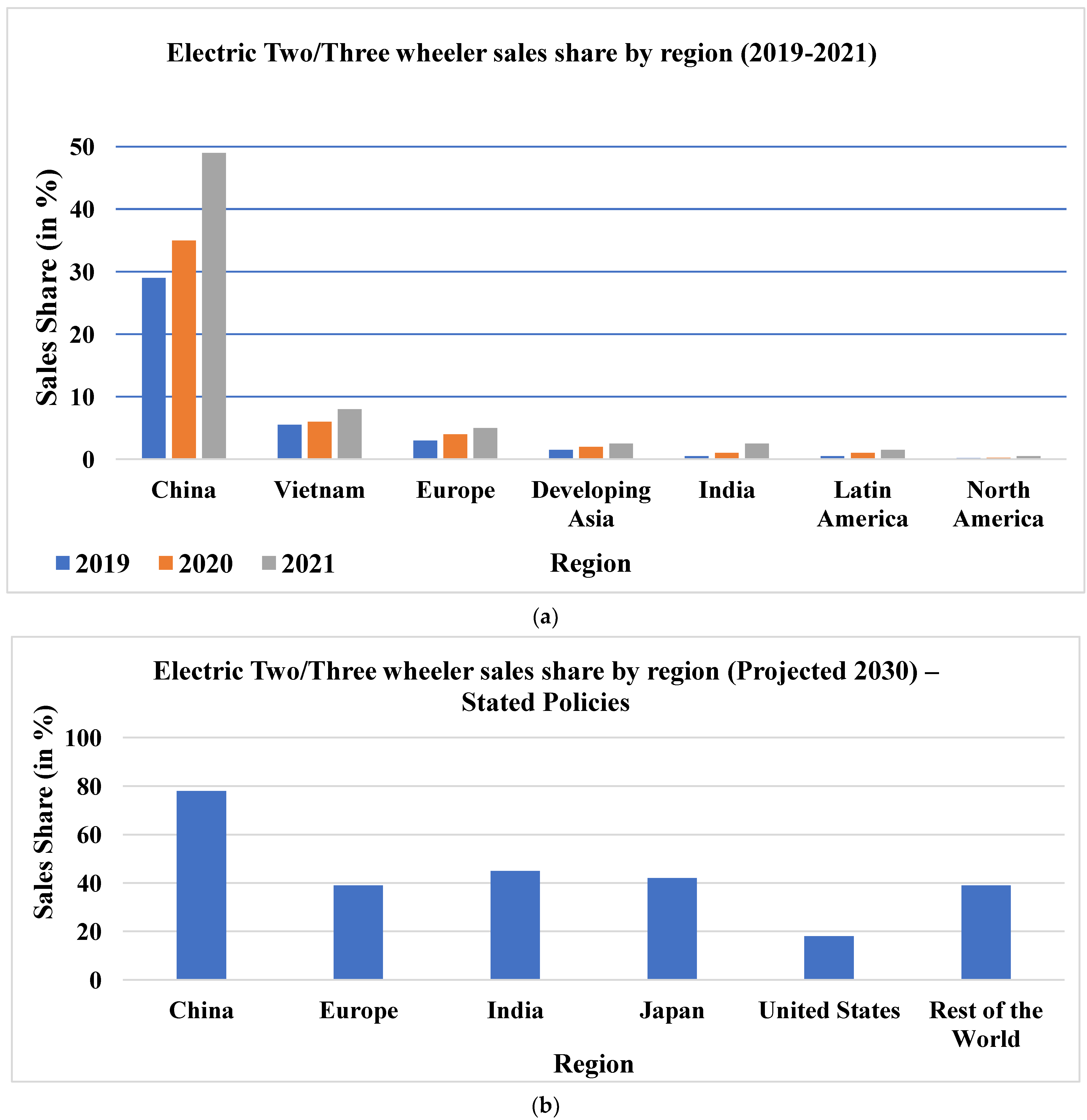
Figure 1. Electric vehicle sales trend in various regions. (a) Growth from 2019 to 2021 (b) Projected sales by 2030 [1].
Applsci 13 01676 g001
Figure 2. Block diagram schematic for on-board charging.
Applsci 13 01676 g002
Figure 3. Block diagram schematic for off-board charging.
Applsci 13 01676 g003
Figure 4. (a) Methodology workflow for this review study (b) Hierarchy for segregation of collected articles.
Applsci 13 01676 g004
Figure 5. Isolated Cuk converter with canonical switching cell PFC [35].
Applsci 13 01676 g005
Figure 6. Isolated SEPIC converter with DBR back end [36].
Applsci 13 01676 g006
Figure 7. Flyback converter with Zeta-SEPIC PFC stage [37].
Applsci 13 01676 g007
Figure 8. Bridgeless positive output Luo converter [18].
Applsci 13 01676 g008
Figure 9. Bridgeless isolated Zeta converter with PV-fed Cuk converter [19].
Applsci 13 01676 g009
Figure 10. Two-stage charger with Cuk converter front-end and half-bridge LLC back-end [21].
Applsci 13 01676 g010
Figure 11. Full bridge LLC converter [22].
Applsci 13 01676 g011
Figure 12. (a) Interleaved isolated Luo converter-based topology [45] (b) Interleaved isolated SEPIC converter-based topology [46].
Applsci 13 01676 g012
Figure 13. Bridgeless switched inductor SEPIC converter-based topology [53].
Applsci 13 01676 g013
Figure 14. Quadratic buck-boost converter [57].
Applsci 13 01676 g014
Figure 15. LLC converter for LEV charging [16].
Applsci 13 01676 g015
Figure 16. Modular dual active bridge-based charger [63].
Applsci 13 01676 g016
Figure 17. Quasi-resonant interleaved flyback converter [60].
Applsci 13 01676 g017
Figure 18. SEPIC and bidirectional interleaved converter-based charger with standalone PV power supply [70].
Applsci 13 01676 g018
Figure 19. Five-level LLC converter [71].
Applsci 13 01676 g019
Figure 20. Distribution of reviewed papers by type and year.
Applsci 13 01676 g020
Figure 21. Qualitative comparison of (a) On-Board and (b) Off-Board DC-DC converters. On a scale of 1 to 5, 1 = lowest and 5 = highest.
Applsci 13 01676 g021
Figure 22. Schematic block diagram of wireless charging.
Applsci 13 01676 g022
Figure 23. Charging current ibat variation in (a) CC-CV charging mode and (b) Reflex charging mode.
Applsci 13 01676 g023
Table 1. Some commercially available LEVs and their battery/charging specifications.
TypeModelBattery TypeVoltage RatingCapacityCharging TimeFast Charging
Two-wheelerHero Electric Optima CXLi-ion51.2 V30 Ah4–5 hN/A
Okinawa PraiseProLi-ion72 V2 kWh2–3 hN/A
Ather 450 PlusLi-ion51.1 V3.7 kWh5 h 40 min1–2 h
Three-wheelerMahindra TreoLi-ion48 V7.37 kWh3 h 50 minN/A
Piaggio Ape E City/Fixed BatteryLi-ion48 V7.5 kWh3 h 45 minN/A
Terra Motors Y4ALead Acid48 V140 Ah6–8 hN/A
Table 2. Summary of on-board charger DC-DC converters.
Isolated Topologies
Ref.TopologyComponent Count 1Salient FeaturesAreas of Improvement
LCSDTr.
[35]Isolated Cuk converter + interleaved canonical switching cell (CSC) front-end47331
  • Unity power factor operation
  • Low switch count
  • No efficiency data
  • Charging current ripples increase with battery voltage
[36]Isolated SEPIC converter + diode bridge rectifier front-end13111
  • Positive output polarity
  • Unity power factor operation
  • 81% efficiency
  • Simple design
  • Substantial charging current ripple
  • No output inductance
  • Efficiency may be improved
[37]Flyback converter with interleaved Zeta + SEPIC converter front-end34331
  • 92% efficiency
  • Unity power factor operation
  • Low current ripple
  • Conduction losses may be optimized
  • The DC link voltage and capacitance may be optimized
[38]Flyback converter with modified Bridgeless Landsman converter front-end44451
  • Unity power factor operation.
  • Less components conduct during switching interval
  • Low current ripple
  • Near 90% efficiency
  • Negative output polarity.
  • The DC link voltage and capacitance may be optimized
[18]Bridgeless Isolated Positive Output Luo converter23231
  • Simple design
  • Positive output polarity.
  • Near unity power factor operation
  • Low switch count
  • 92% efficiency
  • Snubbers to ensure voltage spike reduction may be used
[19]Bridgeless isolated Zeta converter with PV fed Cuk converter45341
  • Near-unity power factor operation
  • Low switch and component count
  • No efficiency data.
  • High component count
[21]Half-bridge LLC resonant converter with Cuk converter PFC45321
  • Soft switching
  • Near-unity power factor operation
  • 94% efficiency
  • High component count
  • Charging time can be improved
[22]Full-bridge LLC resonant converter23441
  • Soft switching
  • 96.4% efficiency
  • High component count
[23]Half bridge LLC converter with interleaved buck-boost converter front-end54621
  • Near-unity power factor operation
  • Soft switching
  • Over 90% ensured at wider load range
  • Bulky DC link capacitance
  • Snubber may be used for switch voltage spike reduction
  • High component count
[45]Interleaved isolated Luo converter with voltage source converter front-end34401
  • Multistage charging
  • Bidirectional functionality
  • Near-unity power factor operation
  • High switch count
  • No efficiency data
[46]Interleaved isolated SEPIC converter with voltage source converter front-end34401
  • Multistage charging
  • Bidirectional functionality
  • Near-unity power factor operation
  • DC isolation between input and output
  • Positive output polarity
  • High switch count
  • No efficiency data
[47]Interleaved isolated Zeta converter with voltage source converter front-end24401
  • Multistage charging
  • Bidirectional functionality
  • Near-unity power factor operation
  • DC isolation between input and output
  • High switch count
  • No efficiency data
Non-Isolated Topologies
Ref.TopologyComponent Count 1Salient FeaturesAreas of Improvement
LCSDTr.
[53]Bridgeless switched inductor SEPIC converter3224NA
  • Single power conversion stage
  • Near-unity power factor operation
  • Close to 95% efficiency
  • Increased conduction losses due to more diodes in conduction path
  • Charging current ripples may be optimized further
[54]Bridgeless switched inductor Cuk converter3224NA
  • Single power conversion stage
  • Close to 92% efficiency
  • Increased conduction losses due more diodes in conduction path
  • Input current ripples may be optimized further
[56]Interleaved buck-boost converter with voltage source converter front-end2240NA
  • Low current ripple
  • Low individual current stress.
  • Near-unity power factor operation
  • High switch count.
  • The DC link voltage/capacitance may be optimized
[57]Quadratic buck boost converter with DBR front end2322NA
  • High step up/down gain
  • Low current ripple
  • Low switch count
  • No efficiency data
  • Supply THD may be optimized further
  • Passive component count relatively high
1 Only DC-DC stages are considered; L—inductor; C—Capacitor; S—Active switch; D—Diode; Tr.—Transformer.
Table 3. Summary of off-board charger DC-DC converters.
Isolated Topologies
Ref.TopologyComponent Count 1Salient FeaturesAreas of Improvement
LCSDTr.
[16]LLC resonant converter29541
  • Soft switching
  • Suitable with wide load range
  • Cascade switch structure ensures low voltage stresses
  • No efficiency data
  • Component count optimization
  • Increased control complexity
[60]Quasi-resonant interleaved flyback converter024 21203 3
  • Bidirectional capability
  • Converter operates in critical conduction mode, thus reducing RMS current
  • Soft switching
  • Resonant converters absorb excess energy during turn off
  • Soft switching is ensured through low voltage switching during charging, and not at the zero point
[63]Modular dual active bridge converter611603
  • Suitable for wide load range
  • Output current sharing is ensured through output parallel structure
  • Input voltage sharing ensured through input series structure
  • Switch count may be optimized
  • Transformer leakage inductance may result in voltage spikes across switches
Non-Isolated Topologies
Ref.TopologyComponent count 1Salient FeaturesAreas of improvement
LCSDTr.
[68]PV-fed SEPIC converter3311NA
  • Positive output polarity.
  • Simple design
  • PV MPPT and charging control applied simultaneously
  • Satisfactory dynamic performance under varying PV irradiation
  • Increased control complexity
[70]PV-fed SEPIC converter with backup battery-fed interleaved bidirectional converter 710 2101NA
  • Simple design
  • Satisfactory performance under dynamic irradiation conditions
  • 96% charging efficiency observed in all modes of operation
  • Increased control complexity
[71]Multilevel LLC converter2484NA
  • Transformerless design reduces cost
  • High frequency operation
  • Soft switching
  • Efficiency of approximately 97%
  • Two different DC input supplies.
  • High switch count
  • Increased frequency selectivity for soft switching
1 Only DC-DC stages are considered; L—inductor; C—Capacitor; S—Active switch; D—Diode 2 Includes capacitance across switch. 3 Three-winding transformer.
Table 4. Summary of some recent wireless LEV charger implementations.
No.ReferenceSalient Features
1.[4]
  • Receiver coil is embedded into the e-bike’s kickstand.
  • Use of capacitors in the circuit helps in enhancing power transfer capability.
  • Misalignment issue is addressed through the use of auto-resonant frequency control, but this may also increase control complexity.
  • Additional DC-DC stage may affect efficiency.
2[83]
  • Two/three coil hybrid wireless charging topology is presented.
  • Scheme is used to charge multiple bikes at once.
  • For compensation of reactive power, an inductor array is attached on the primary side.
  • Issue of misalignment is not addressed in this work
  • Charging efficiency of approximately 91% is achieved.
3[84]
  • Three-coil structure-based wireless charger for e-bike is presented.
  • A primary-side load identification technique is employed to control the transition between constant current and constant voltage mode, thus eliminating sensing requirement on secondary side.
  • Charging efficiency of approximately 91% is achieved.
Table 5. Summary of discussed control techniques.
No.Control TechniqueSalient Features
1.Constant Current/Constant Voltage (CC-CV)
  • Most popular control technique for EV charging applications.
  • CC stage—increase in battery voltage up to certain state of charge.
  • CV stage—decrease in charging current.
  • Has limitations such as long charging time, lower efficiency, hence not suitable for fast charging applications.
2Reflex charging
  • Allows for larger charging current to be injected in pulses.
  • Additionally involves negative pulse and rest periods to preserve battery life.
  • It has the limitation of lower average charging current due to negative pulse period.
  • This can be overcome by choosing appropriate pulse widths and charging current amplitudes.
3Constant temperature (CT)
  • Nascent charging technique, which allows charging within a limited temperature band.
  • Charging current is dynamically set according to the battery temperature.
Disclaimer/Publisher’s Note: The statements, opinions and data contained in all publications are solely those of the individual author(s) and contributor(s) and not of MDPI and/or the editor(s). MDPI and/or the editor(s) disclaim responsibility for any injury to people or property resulting from any ideas, methods, instructions or products referred to in the content.