Article

Design and Mechanical Properties Analysis of Variable Buffer-Force Planing Energy-Absorbing Device for Rail Vehicles

1
School of Mechatronics Engineering, Harbin Institute of Technology, Harbin 150001, China
2
Shenzhen Cansinga Technology Co., Ltd., Shenzhen 518000, China
3
School of Mechanical Engineering, Shandong University of Technology, Zibo 255000, China
*
Authors to whom correspondence should be addressed.
Appl. Sci. 2023, 13(3), 1596; https://doi.org/10.3390/app13031596
Submission received: 15 December 2022 / Revised: 5 January 2023 / Accepted: 6 January 2023 / Published: 26 January 2023

Abstract

:
Collisions between rail transit vehicles are unavoidable. In order to alleviate the disaster caused by the collision, energy-absorbing and shock-absorbing materials are generally installed at the front end of the rail vehicle. In this paper, a variable buffer-force planing energy-absorbing device for rail transit vehicles was prepared. The buffer force was changed by length (Dx), angle (A) and thickness (W). First, we manufactured one type of material, and data were obtained through experimentation. Second, we used Ls-DYNA to simulate this material, and determined the accuracy between the simulation and the test. Third, various parameters of the material were simulated by Ls-DYNA. The results show that changing Dx greatly affects the performance of the material, W has no obvious effect on the performance, and A is important for the materials properties. Based on finite element simulation, the functional model relationship between the average force and various parameters was deduced. This lays the groundwork for the application of the variable buffer-force planing energy absorbing device.

1. Introduction

Collisions are common mechanical phenomena, and include car collisions, ship collisions, plane collisions, etc. The accidents cause a lot of personal and property losses [1]. Therefore, improving the crashworthiness of vehicles has become an attractive object of research, and various energy-absorbing structures have thus emerged [2].
Passive safety relies mainly on the energy-absorbing material at the front end of the frame to absorb external loads. Energy-absorbing devices based on the principles of composite material crushing and polymer material friction have emerged in recent years [3], metal deformation energy-absorbing structures have the advantages of high efficiency, good manufacturability and low price [4]. Therefore, metals are still the first choice in various collision situations. Scholars have conducted a large number of impact tests and simulation analyses on energy-absorbing structures [5,6,7], analysing the crashworthiness of the energy-absorbing structures and summarizing their design methods. Common metal deformation energy-absorbing structures include metal thin-wall crushing, metal tube expansion and metal cutting, etc. [8,9,10]. Among these, the thin-walled metal crush structure is the most widely used because of its economy and simplicity, leading this type of structure to be the object of most research. Baroutaji et al. [11] have summarized the influencing factors of thin-walled energy-absorbing elements and their design and optimization methods. A large number of articles [12,13,14,15] have summarized the influencing factors of thin-walled energy-absorbing elements under axial compression, have analysed the deformation patterns of thin-walled tubes under different loading conditions, and have proposed an average crushing force for square and round tubes.
Although the specific energy absorption of the lateral crushing and bending deformation of thin-walled components is small. In actual collisions, energy absorption caused by lateral loads is inevitable. The crashworthiness of thin-walled components has been analysed [16,17,18]. Metal tube expansion structures are widely used in rail vehicles, and the research on such energy-absorbing structures is similarly in-depth. Shakeri has stated that an expanded tube structure could still maintain good crashworthiness and energy absorption efficiency under different external force loading conditions, and they analysed the geometric dimensions, material strength, diameter expansion of the expanded tube in detail through experiments, simulations and theoretical derivation.
Energy absorption of the expander energy absorber have also been researched [16,17,18]. Li et al. [19] propose a new hybrid absorber with an external die added to the outside of the expanding–splitting tube. Experimental results show that the hybrid tube deforms in a controlled manner and has a high energy absorption. Salman et al. [20] proposes a novel design of regenerative shock absorber for the in-wheel motor. Their results show that the shock absorber is effective and feasible for renewable energy applications in electric vehicles. Research on the energy absorption mechanism and structural design of metal expansion tubes is also now relatively mature. The energy-absorbing structure based on the principle of metal cutting has the advantages of compact structure and high volume-specific energy-absorbing efficiency [21], and its application in the engineering field has gradually increased in recent years [22]. Dubey et al. [23] endeavoured to accentuate the material response at high strain rates as well as the structural response, with their results showing a good absorption of energy. John et al. [24] derived an analytical modelling procedure to predict the complete force-displacement response. The mean load and total energy absorption were predicted to within 5% of experimental values. In recent years, with the increasing application of energy-absorbing components, many scholars have proposed new structures based on this energy-absorbing principle, the influence of relevant parameters on the energy absorption capacity of the structure has been analysed in detail, and the relevant design and optimization methods have been proposed [25,26].
From the paper on the existing metal-cutting energy-absorbing structures, it is found that the researchers are most concerned about the parameters affecting the change of cutting force, because these are closely related to the energy-absorbing capacity of the structure. For the influencing factors of cutting force, in addition to the experimental test, simulation and theoretical derivation were used. Xie obtained the cutting force calculation formulae for turning and groove cutting through mathematical derivation [27]. The general simulation analysis method for analysing different machining methods can better predict the cutting force in machining. To sum up, many people have carried out research on the energy absorption characteristics of metal plastic deformation-type energy-absorbing elements [28,29,30], and there are an increasing amount of metal-cutting energy-absorbing elements to be researched. In order to improve the crashworthiness of the structure, the buffering structure needs to increase the energy-absorbing stroke [31]. Zhang, Yang, Li, et al., applied the variable-buffer force structure to a rail vehicle, which greatly improved the energy absorption capacity of the vehicle, and effectively improved its crashworthiness [32,33,34].
Mahmoud et al. [35] introduced a novel method to enhance absorbed energy by square sections. Specific absorbed energy by open and closed sections is calculated. Meng et al. [36] investigated the cutting strain of the combined honeycomb core considering the effects of core diameter, explosive charge mass and scaled distance, with their results demonstrating that either a decreasing scaled distance or an increasing charge mass results in a larger cutting strain. Guan et al. [37] conducted a quasi-static cutting experiment on an aluminium tube, and it was shown that the cutting aluminium tube absorber presents a stable deformation mode.
The purpose of this paper is to propose a cutting energy-absorbing structure that can control the buffer force according to the actual situation, and to study the influencing factors of the buffer force of the metal cutting energy-absorbing structure under high speed and large cutting depth. A calculation formula for cutting buffer force considering parameters was obtained, and provides a design basis for variable cutting force energy-absorbing structures.

2. Experiments

2.1. Test Equipment

The characteristics of energy-absorbing components are often tested with static pressure or impact equipment. The test in this paper uses a drop-weight impact equipment. The test is shown in Figure 1, from top to bottom: the hammer head and counterweight are located at the top, and the collision speed and energy are controlled according to their lifting height (0∼20 m) and counterweight mass (420∼1200 kg). The energy structure (including the cutting specimen, tool and flange) is installed on a fixed tool to absorb the kinetic energy of the falling hammer. The piezoelectric impact force sensor measures the impact force during the collision at the bottom of the installation tool.
The pressing tool is used to ensure that the test specimen does not overturn and move during the test. The magnetic grating sensor and the magnetic grating ruler are respectively installed on the side of the track and the drop weight frame to measure the energy absorption stroke. In addition, the high-speed camera is arranged at a distance of 1.5 m from the test specimen, with a speed of 2000 frames per second. The test process is recorded at shooting speed.

2.2. Preparation and Description of Test Specimen

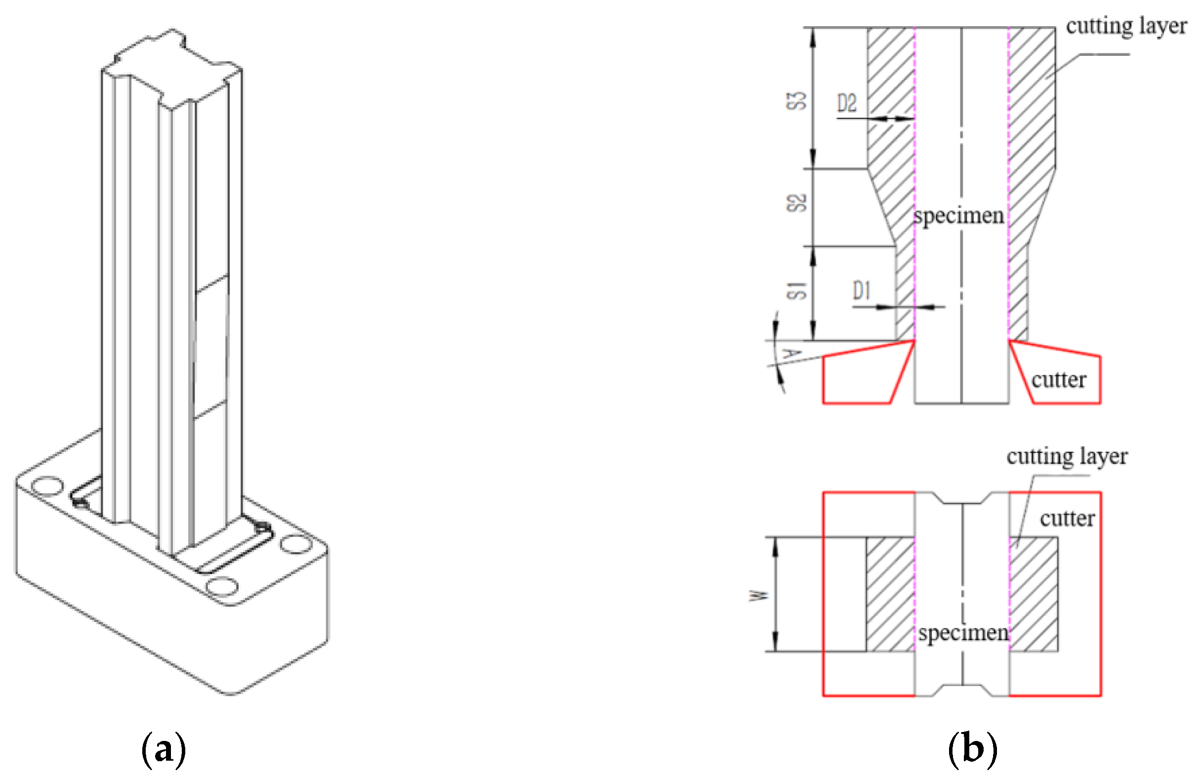
The specimen in this paper is a specially designed variable buffer force energy-absorbing element, mainly composed of flanges, tools and workpieces. The assembly relationship is shown in Figure 2a. The function of the workpiece to be cut is divided into two parts. Firstly, the guiding part is processed into the shape of a dovetail groove, so that the workpiece to be cut can move stably in the vertical direction during the collision process. Secondly, the cut part is used to absorb the collision energy, and the cut part changes the cutting force by controlling the thickness of the cutting layer.
The part is divided into three stages: the cutting depth in the first stage is a constant value D1, the cutting depth in the second stage increases linearly from D1 to D2. The cutting depth in the third stage is a constant value D2, and the strokes of the three stages are S1, S2, and S3, respectively. A represents the cutting angle and W represents the thickness of material. The profile of the specimen and the definition of related parameters are shown in Figure 2.
The relevant parameters selected in this experiment test are shown in Table 1. The material of the tool is cemented carbide, and the material of the cut specimen is Q235.

2.3. The Simulation Model

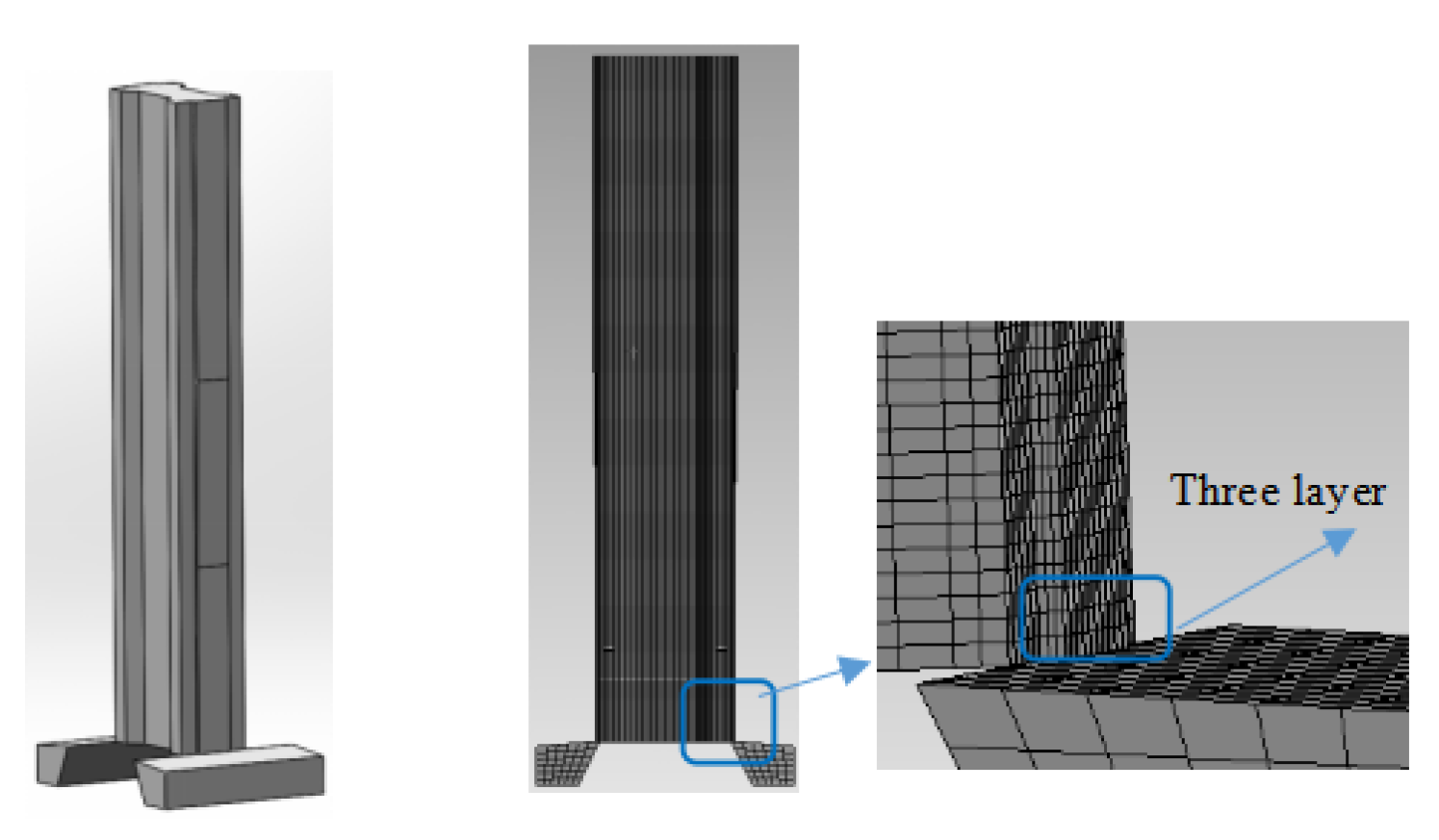
This paper uses the finite element analysis software Abaqus for calculation. The 3D model is generated by Solidworks, the model size is the same as the test size, tools are added on both sides of the lower end, then the model is imported into the simulation software using the IGS format. The tool is selected as cemented carbide, the energy-absorbing element is Q235 steel, and the relevant parameters of the material are referenced from [38] in order to speed up the calculation speed and reduce the use of computer resources. We set the material and tool to different mesh sizes. Reference [39] shows when the ratio of mesh size to element size is 0.125 (mesh size/element size = 0.125), the simulation results agree well with the experimental results. The contact form is set to bonding, the material body is self-contact, the type is friction, the static friction force is set to 0.3, and the dynamic friction force is set to 0.2 [40]. The X and Y axes are fixed, the loading displacement is set to the Z direction (equal to 300 mm). In order to speed up the calculation, the loading time to is set to 0.001 s for calculation.
The simulation model is shown in Figure 3.
In the simulation, meshes of different sizes are used, and local fine meshing is performed on the parts of the energy-absorbing element (especially the parts that need to be cut) to ensure that the thinnest part of the mesh also has three layers (Figure 3).

3. Results and Discussion

3.1. Test Results

We installed the specimen on the equipment and lifted the drop weight (the total weight of this test drop weight and counterweight is 1040 kg) to a height of 4.5 m from the upper surface. The hammer then falls freely under gravity, contacts the specimen at a high speed, and then the specimen moves downward at the same speed. During the movement, the tool cuts the metal specimen to absorb the kinetic energy of the falling hammer. The following picture shows the collision process recorded by high-speed photography (Figure 4). From the moment of contact between the drop weight and the energy-absorbing structure at 0 to 42 ms, the chips gradually increase in a curled shape as time moves forward (Figure 4, marked yellow).
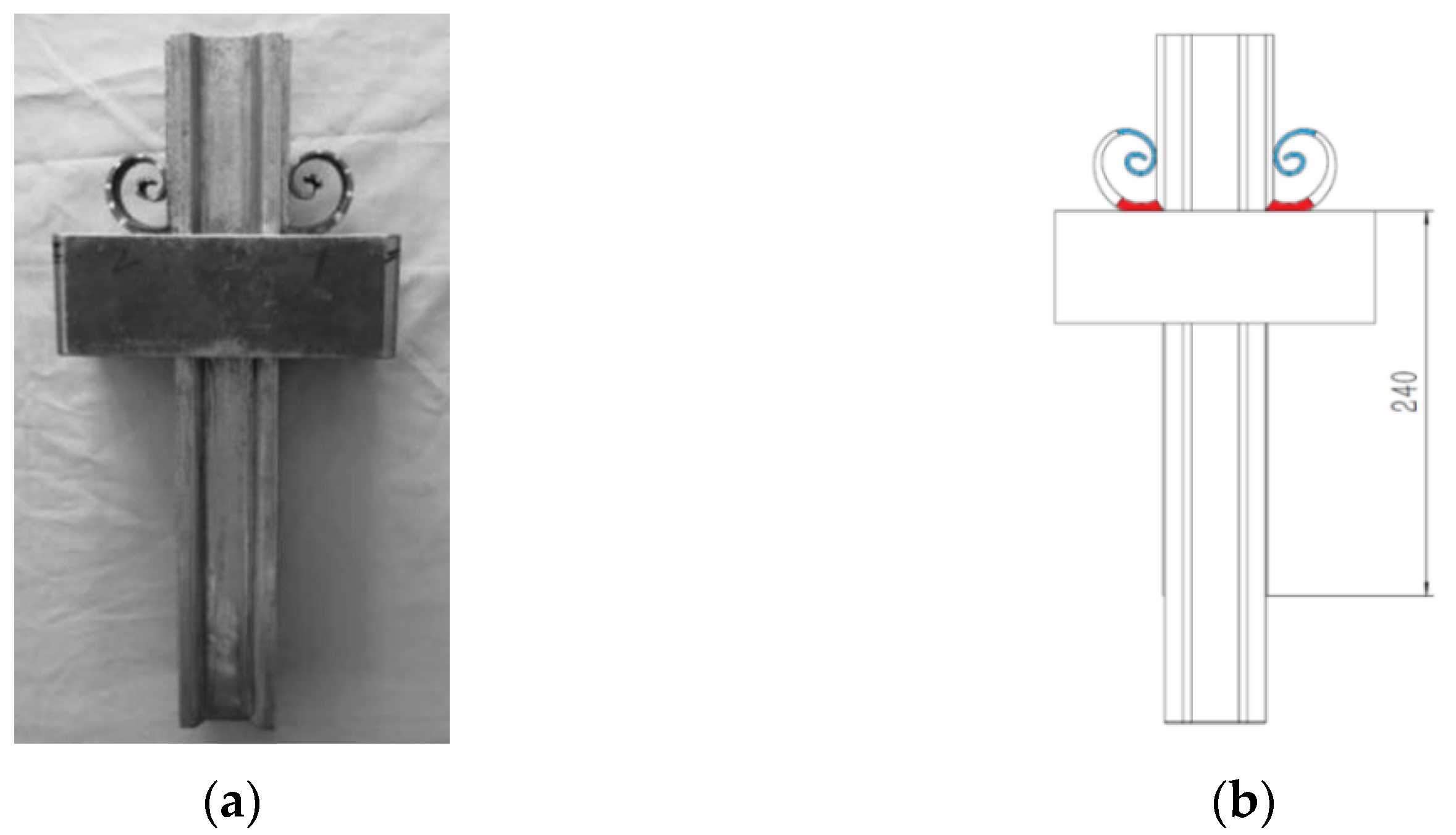
The specimen after the collision is shown in Figure 4. The total energy absorption stroke is 240 mm. The chips on both sides of the specimen are basically symmetrically distributed (Figure 5). The thickness of the chips is divided into three sections, with the thickness of the initial section being about 2.7 mm (Figure 4 marked blue), the middle transition segment increasing from 2.7 mm to 5.5 mm (marked white), and the thickness of the final segment being about 5.5 mm (marked red).
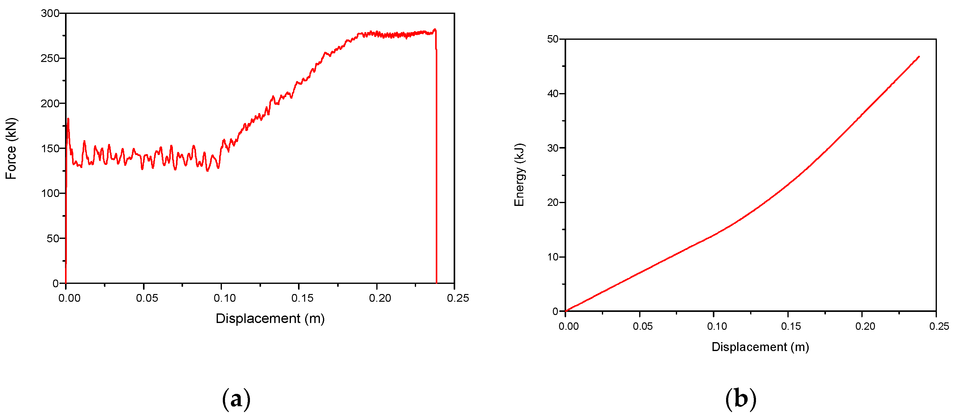
The curves of the buffer force-stroke and energy absorption-stroke are shown in Figure 6. From the curve analysis, we find that the collision process is divided into four stages. The first stage represents the moment when a large peak force occurs in the contact between the hammer head and the specimen at the starting section, with the stroke being about 3 mm. The buffer force in the second stage is maintained at around 140 kN, and the stroke is about 97 mm. The buffer force in the third stage is gradually increased from 140 kN to 280 kN, and the stroke is about 96 mm. The buffer force in the fourth stage is around 280 kN until the end of the test, and the stroke is about 42 mm. (Initial velocity is 9.39 m/s).

3.2. Simulation Results

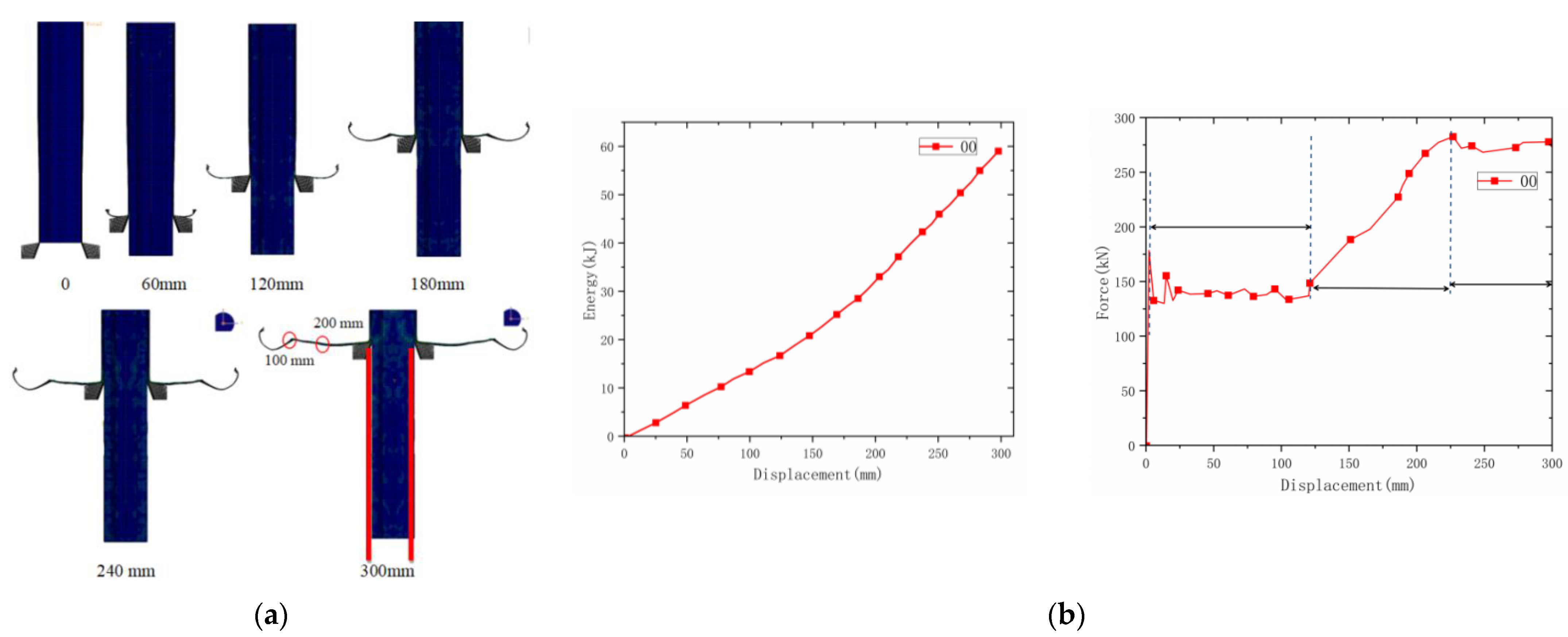
The simulation process of the material is as follows. The tool is first placed at the bottom of the material. The simulation process adopts the loading method of fixing the specimen and moving the tool, and taking pictures at an interval of 60 mm. The deformation process is shown in Figure 7a. Comparing the simulation (Figure 7b) and experiment test results, it can be found that the deformation of the stress–strain curves of the simulation and the test are relatively similar under the same loading conditions with the same specifications and parameters.
In the range of the deformation amount of 300 mm, the stress of the material has four distinct stages. These are the initial elastic stage, the first plateau stage, the stress rising stage and the second plateau stage. The initial elastic stage occurs at the beginning of the material. This part is an oblique line until the plastic strain of the material is reached; after that, the material shows a small stress drop, the material begins to fail, and then the material deforms with a relatively stable stress. The continuous range of this stage is about the length of S1; after reaching the starting point of S2, S2 is a material fracture length with a variable slope, so the stress increases according to a certain slope, and the magnitude of the increase is related to the slope of the material thickness. When the material enters S3, the thickness of S3 is two times that of S1, and it is also a cuboid region from the side, and its stress is stable, at about two times that of S1.
Observing the morphology of the material after cutting, it can be found that the material on both sides is cut off, and the sides are straight, as shown by the red line (Figure 7a).
From the deformation process diagram, it can be found that there are two obvious inflection points in the material, that is, the curling of the material changes significantly (Figure 7a), these occur at 100 mm and 200 mm of the material’s deformation.

4. Parametric Analysis

Some studies have shown that the main factors that have a great impact on the cutting force are depth of cutting, width, rake angle, friction coefficient (tensile strength, flow shear strength), material strength and cutting speed. However, by analysing the buffer force-stroke curve in Figure 5a, it is found that the cutting speed decreases during the collision process but the cutting force remains basically unchanged. Therefore, it can be considered that the average buffer force of the buffer structure under large cutting depth is affected by the cutting speed. Assuming that the average buffer force F of the energy-absorbing structure is a function related to the structural parameters of the cutting depth D, the width W, and the rake angle A, the general model is established as follows: c is constant, x1, x2, x3 are exponent, and σ is material strength (Formula (1)).
F = c × D x 1 W x 2 A x 3 σ
In order to better reflect the influence of various parameters on the average buffer force, a total of 28 sets of simulation tests have been designed in this paper. The relevant parameters and simulation results are shown in Table 2. The average cutting force in the table is a calculated value. The total kinetic energy absorbed is divided by the total energy absorption stroke. The Formula (2) is as follows:
F = E / L
The collision simulation deformation diagram and force-displacement curve of each parameter are shown in Supplementary Materials. It can be seen from Table 2 that the energy absorption of the material can be changed according to the parameter change. When the device is applied to a rail vehicle as a shock absorption device, the structural size of the device can be reversely deduced according to the mass and running speed of the rail vehicle. Thereby, it can achieve the purpose of protecting rail vehicles.

4.1. Influence Factors of Average Buffering Force

C, A, and f are all dimensionless constants, σ is the material strength (235 MPa), and A is the sin value of the rake angle; therefore, in order to make the dimensions on both sides of the following Formula (3) consistent according to the results of the parametric simulation, the influence of the three parameters on the average buffer force is analysed respectively.
F = C × x 1 a x 2 b x 3 c σ
According to the results in Table 2, we fit the Formula (4) to obtain the average buffer force (Formula (5)):
ln F = ln C + a ln x 1 + b ln x 2 + c ln x 3
According to Supplementary Materials, we get the significant degree of influence W > D2 > A.
F = 235 × 0.7859 × D 2 0.759 × W 1.2246 × ( sin A ) - 0.1584

4.2. Influence of Dx on Material Properties

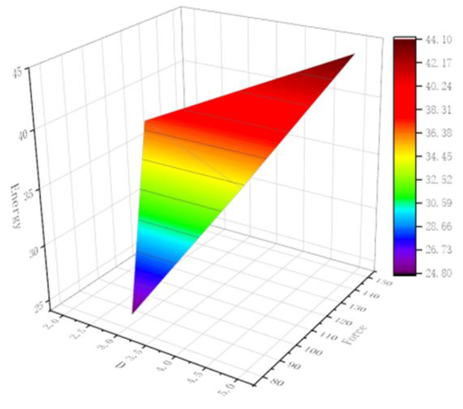
Through the obtained parameterization results (Table 3), the influence of each parameter on the mechanical properties of the material is studied. First, the influence of Dx on the material properties is studied. The W and A values are fixed at W = 20, A = 5. When the D value changes, the material properties are changed. When D2 changes, the force of the material shows a fluctuating trend, which indicates that the change of Dx will greatly affect the performance of the material. Figure 8 shows the cutting zone of variable buffer-force planing. Figure 9 shows the 3D figure of Dx–energy–force.

4.3. Influence of W on Material Properties

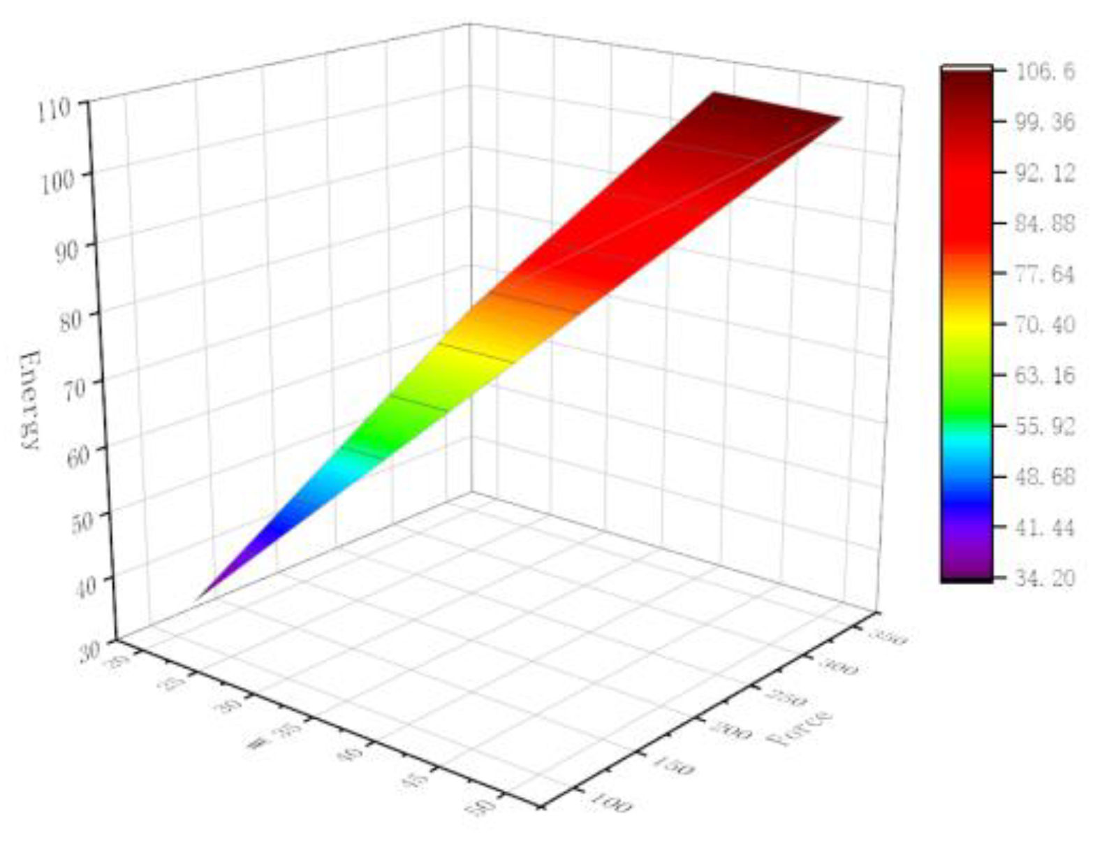
We fixed D2 and A so that D2 = 4 and A = 5. We then studied the change of material properties when the W value changes (Table 4). When W increases, the average force of the material gradually increases. When the W is 40 and 50 mm, the change of the average force is not obvious, which indicates that when the width of the cutting material reaches a certain value, the change of the average force is not obvious. Figure 10 shows the 3D figure of W–Energy–Force.

4.4. Influence of A on Material Properties

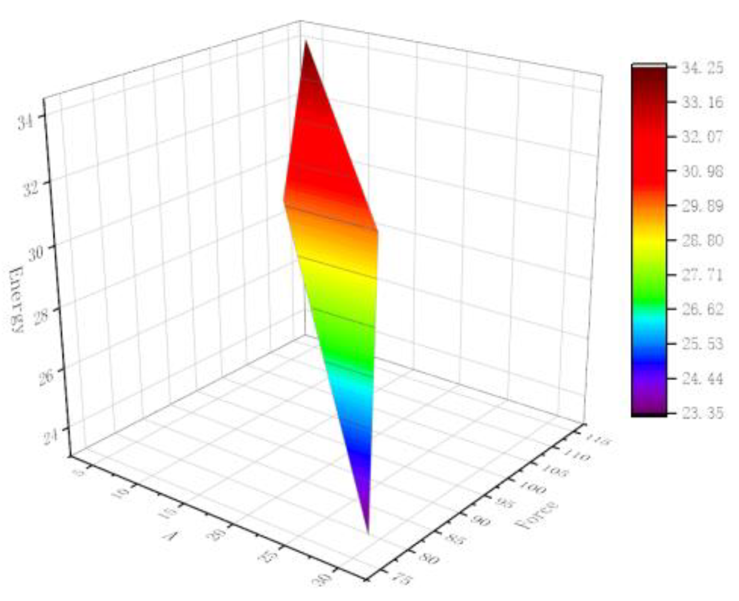
We fixed D2 and W so that D2 = 4 and W = 20. We then studied the change of material properties when the A value changes (Table 5). As A increases, the average force of the material decreases gradually. Figure 11 shows the 3D figure of A–energy–force.

5. Conclusions

This paper proposed a cutting energy-absorbing structure that can control the buffer force according to the actual situation and studied the influence factors of the buffer force of the metal-cutting energy-absorbing structure under high speed and large cutting depth. A calculation formula of cutting buffer force considering parameters such as material length, width and cutting inclination was obtained, providing a design basis for variable cutting-force energy-absorbing structures.
  • A controllable buffering energy-absorbing structure whose buffering force can change with the stroke was proposed. The mechanical properties and deformation process of the material were studied by means of experiments and simulations. The influencing factors of the average force of the metal cutting buffer structure and its influence trend were described.
  • The calculation formula of an average buffer force considering material strength and friction coefficient was obtained. As A increases, the average force of the material decreases gradually. When W increases, the average force of the material gradually increases, and when the width of the cutting material reaches a value, the average force does not change significantly. D can greatly affect the properties of the material.
  • Through experiments, it was found that the buffer force of the structure will not change significantly due to the change of cutting speed. Finally, we obtained the significant degree of influence W > D2 > A. We fit the formula to obtain the average buffer force F = 235 × 0.7859 × D 2 0.759 × W 1.2246 × ( sin A ) - 0.1584 .

Supplementary Materials

The following supporting information can be downloaded at: https://www.mdpi.com/article/10.3390/app13031596/s1.

Author Contributions

Methodology, H.W.; Software, F.Z.; Formal analysis, R.L.; Investigation, Y.X.; Writing—original draft, W.W. All authors have read and agreed to the published version of the manuscript.

Funding

This research received no external funding.

Institutional Review Board Statement

Not applicable.

Informed Consent Statement

Not applicable.

Data Availability Statement

Data will be made available on request.

Conflicts of Interest

The authors declare no conflict of interest.

References

  1. Yahia, H.; Yousuf, I.; Sheriyani, A.A. Implementing Specific Interventions to Reduce of Roads Traffic Accidents in Oman. In Proceedings of the International Traffic Safety Conference, Doha, Qatar, 26–27 November 2018. [Google Scholar]
  2. Noorsumar, G.; Rogovchenko, S.; Robbersmyr, K.G.; Vysochinskiy, D. Vehicle crashworthiness performance in frontal impact: Mathematical model using elastic pendulum. Mech. Res. Commun. 2022, 124, 103954. [Google Scholar] [CrossRef]
  3. Grotto, F.; Rivallant, S.; Bouvet, C. Development of a 3D finite element model at mesoscale for the crushing of unidirectional composites: Application to plates crushing. Compos. Struct. 2022, 287, 115346. [Google Scholar] [CrossRef]
  4. Zou, Q.; Zhou, X.; Wang, R.; Ning, Y.; Chen, Z.; Kong, F.; Liu, Y. Load-carrying and energy-absorbing performance of honeycombs with different cross sections under cyclic loading. Mat. Today Commun. 2022, 33, 104582. [Google Scholar] [CrossRef]
  5. Feng, Z.; Xie, S.; Ma, W.; Jing, K.; Wang, H. Multi-tube energy-absorbing structures with different matching patterns of heights and diaphragm spacings. Alex. Eng. J. 2022, 61, 11111–11127. [Google Scholar] [CrossRef]
  6. Isaac, C.W.; Ezekwem, C. A review of the crashworthiness performance of energy absorbing composite structure within the context of materials, manufacturing and maintenance for sustainability. Compos. Struct. 2021, 257, 1–32. [Google Scholar] [CrossRef]
  7. Peng, Y.; Deng, W.; Xu, P.; Yao, S. Study on the collision performance of a composite energy-absorbing structure for subway vehicles. Thin-Walled Struct. 2015, 94, 663–672. [Google Scholar] [CrossRef]
  8. Mansor, M.A.; Ahmad, Z.; Abdullah, M.R. Crashworthiness capability of thin-walled fibre metal laminate tubes under axial crushing. Eng. Struct. 2022, 252, 113660. [Google Scholar] [CrossRef]
  9. Liu, Y.; Qiu, X.M. A theoretical study of the expansion metal tubes. Int. J. Mech. Sci. 2016, 114, 157–165. [Google Scholar] [CrossRef]
  10. Abouridouane, M.; Bergs, T.; Schraknepper, D.; Wirtz, G. Friction behavior in metal cutting: Modeling and simulation. Procedia CIRP 2021, 102, 405–410. [Google Scholar] [CrossRef]
  11. Baroutaji, A.; Sajjia, M.; Olabi, A.G. On the crashworthiness performance of thin-walled energy absorbers: Recent advances and future developments. Thin-Walled Struct. 2017, 118, 137–163. [Google Scholar] [CrossRef]
  12. Wang, S.; Zhang, M.; Pei, W.; Yu, F.; Jiang, Y. Energy-absorbing mechanism and crashworthiness performance of thin-walled tubes diagonally filled with rib-reinforced foam blocks under axial crushing. Compos. Struct. 2022, 299, 116149. [Google Scholar] [CrossRef]
  13. Paz, J.; Costas, M.; Delgado, J.; Romera, L.; Díaz, J. Energy Absorption of Aluminium Extrusions Filled with Cellular Materials Under Axial Crushing: Study of the Interaction Effect. Appl. Sci. 2020, 10, 8510. [Google Scholar] [CrossRef]
  14. Yin, Z.; Shao, Z.; Qi, C.; Wu, H.; Wang, J.; Gao, L. Static Compressive Properties of Polypropylene Fiber Foam Concrete with Concave Hexagonal Unit Cell. Appl. Sci. 2023, 13, 132. [Google Scholar] [CrossRef]
  15. de la Rosa, Á.; Ruiz, G.; Poveda, E. Study of the Compression Behavior of Steel-Fiber Reinforced Concrete by Means of the Response Surface Methodology. Appl. Sci. 2019, 9, 5330. [Google Scholar] [CrossRef] [Green Version]
  16. Wang, Y.; Rong, R.; Liu, S.; Zhai, X.; Zhi, X. Energy absorption behaviour of an aluminium foam-filled circular-triangular nested tube energy absorber under impact loading. Structures 2021, 34, 95–104. [Google Scholar] [CrossRef]
  17. Yan, J.; Yao, S.; Xu, P.; Peng, Y.; Shao, H.; Zhao, S. Theoretical prediction and numerical studies of expanding circular tubes as energy absorbers. Int. J. Mech. Sci. 2016, 105, 206–214. [Google Scholar] [CrossRef]
  18. Chahardoli, S.; Alavi Nia, A.; Asadi, M. Parametric investigation of the mechanical behavior of expanding-folding absorbers and their implementation in sandwich panels core. Thin-Walled Struct. 2019, 137, 53–66. [Google Scholar] [CrossRef]
  19. Li, J.; Xie, Z.; Yu, Y.; Gong, X.; Gao, G. Experimental and numerical study on the crashworthiness performance of a hybrid energy absorber with expanding–splitting–bending process. Thin-Walled Struct. 2022, 181, 110122. [Google Scholar] [CrossRef]
  20. Salman, W.; Zhang, X.; Li, H.; Wu, X.; Li, N.; Azam, A.; Zhang, Z. A novel energy regenerative shock absorber for in-wheel motors in electric vehicles. Mech. Syst. Signal Process. 2022, 181, 109488. [Google Scholar] [CrossRef]
  21. Wierzbicki, T.; Recke, L.; Abramowicz, W.; Gholami, T.; Huang, J. Stress profiles in thin-walled prismatic columns subjected to crush loading-II. Bending. Comput. Struct. 1994, 51, 625–641. [Google Scholar] [CrossRef]
  22. Wu, F.; Liu, Z.; Guo, B.; Sun, Y.; Chen, J. Research on the burr-free interrupted cutting model of metals. J. Mater. Process. Technol. 2021, 295, 117190. [Google Scholar] [CrossRef]
  23. RDubey, R.; Jayaganthan, R.; Ruan, D.; Gupta, N.; Jones, N.; Velmurugan, R. Velmurugan, Energy absorption and dynamic behaviour of 6xxx series aluminium alloys: A review. Int. J. Impact Eng. 2023, 172, 104397. [Google Scholar]
  24. Magliaro, J.; Altenhof, W. Analytical predictions of the complete mechanical response of AA6061 energy absorbers subjected to axial cutting. Thin-Walled Struct. 2019, 139, 151–168. [Google Scholar] [CrossRef]
  25. Mahdavi, S.; Mahmoodi, A.; Pasandidehpoor, M.; Marzbanrad, J. Experimental and numerical investigation on cutting deformation energy absorption in circular tubes under axial impact loading by damage criterions. Thin-Walled Struct. 2017, 120, 269–281. [Google Scholar] [CrossRef]
  26. Hao, Y.; Wu, Y.; Ranjith, P.; Zhang, K.; Hao, G.; Teng, Y. A novel energy-absorbing rock bolt with high constant working resistance and long elongation: Principle and static pull-out test. Constr. Build. Mater. 2020, 243, 118231. [Google Scholar] [CrossRef]
  27. Xie, S.; Zhang, J.; Liu, X.; Zheng, S.; Liu, Z. A reinforced energy-absorbing structure formed by combining multiple aluminum foam-filled open-hole tubes. Int. J. Mech. Sci. 2022, 224, 107319. [Google Scholar] [CrossRef]
  28. Shen, X.; Zhang, D.; Yao, C.; Tan, L.; Li, X. Research on parameter identification of Johnson–Cook constitutive model for TC17 titanium alloy cutting simulation. Mater. Today Commun. 2022, 31, 103772. [Google Scholar] [CrossRef]
  29. Wang, J.; Lu, Z.; Zhong, M.; Wang, T.; Sun, C.; Li, H. Coupled thermal–structural analysis and multi-objective optimization of a cutting-type energy-absorbing structure for subway vehicles. Thin-Walled Struct. 2019, 141, 360–373. [Google Scholar] [CrossRef]
  30. Sharifzadeh, M.; Lou, J.; Crompton, B. Dynamic performance of energy-absorbing rockbolts based on laboratory test results. Part I: Evolution, deformation mechanisms, dynamic performance and classification. Tunn. Undergr. Space Technol. 2020, 105, 103510. [Google Scholar] [CrossRef]
  31. Li, W.; Fan, H.; Bian, Y.; Yang, F. Plastic deformation and energy absorption of polycrystalline-like lattice structures. Mater. Des. 2021, 198, 109321. [Google Scholar] [CrossRef]
  32. Zhang, H.; Peng, Y.; Hou, L.; Tian, G.; Li, Z. A hybrid multi-objective optimization approach for energy-absorbing structures in train collisions. Inf. Sci. 2019, 481, 491–506. [Google Scholar] [CrossRef]
  33. Yang, C.; Zhao, Z.; Guo, W.; Xu, P.; Zhou, S.; Yan, L.; Jin, X. Parametric beam-based crashworthiness optimisation for the crush zone of a subway vehicle. Thin-Walled Struct. 2023, 183, 110387. [Google Scholar] [CrossRef]
  34. Li, Q.Q.; Li, E.; Chen, T.; Wu, L.; Wang, G.; He, Z. Improve the frontal crashworthiness of vehicle through the design of front rail. Thin-Walled Struct. 2021, 162, 107588. [Google Scholar] [CrossRef]
  35. Mahmoud, Z.; Abbas, N.; Sima, Z. A novel method for enhancing energy absorption capability by thin-walled sections during the flattening process. Thin-Walled Struct. 2015, 97, 140–153. [Google Scholar]
  36. Meng, Y.; Zhang, Y.; Li, X.; Qi, Z.; Lin, Y. Cutting energy absorption property analysis and homogenization analysis of combined honeycomb subject to explosive loading. Thin-Walled Struct. 2022, 170, 108602. [Google Scholar] [CrossRef]
  37. Guan, W.; Gao, G.; Li, J.; Yu, Y. Crushing analysis and multi-objective optimization of a cutting aluminium tube absorber for railway vehicles under quasi-static loading. Thin-Walled Struct. 2018, 123, 395–408. [Google Scholar] [CrossRef]
  38. Schroeder, M.P. Developing CEM Design Standards to Improve Light Rail Vehicle Crashworthiness. In Proceedings of the ASME/IEEE 2006 Joint Rail Conference, Atlanta, GA, USA, 4–6 April 2006. [Google Scholar]
  39. Guo, Z.; Gao, B.; Guo, Z.; Zhang, W. Dynamic constitutive relation based on J-C model of Q235 steel. Explos. Shock Waves 2018, 38, 804–810. [Google Scholar]
  40. Wu, X.; Yu, H.; Guo, L.; Zhang, L.; Sun, X.; Chai, Z. Experimental and numerical investigation of static andfatigue behaviors of composites honeycomb sandwich structure. Compos. Struct. 2019, 213, 165–172. [Google Scholar] [CrossRef]
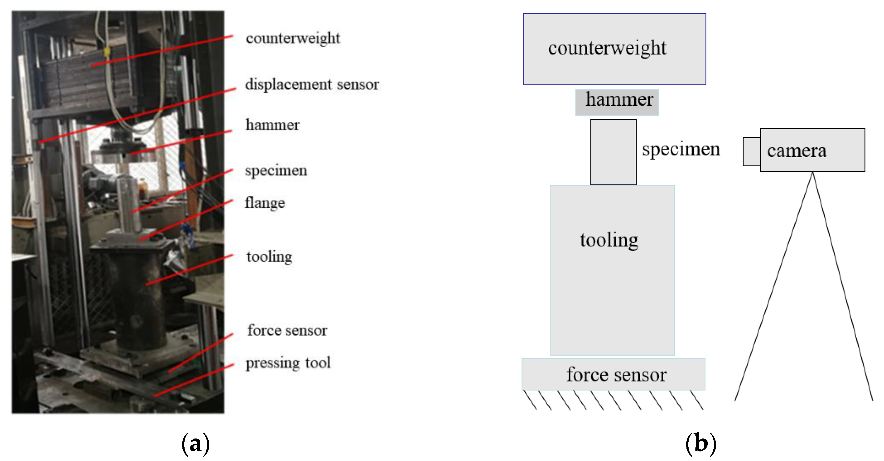
Figure 1. Drop weight impact test. (a) Test diagram; (b) test schematic diagram.
Applsci 13 01596 g001
Figure 2. Energy-absorbing specimen with variable buffer force. (a) Three-dimensional axonometric view; (b) schematic diagram of parameters.
Applsci 13 01596 g002
Figure 3. Simulation Model.
Applsci 13 01596 g003
Figure 4. Test process: (a) 0; (b) 10 ms; (c) 20 ms; (d) 42 ms.
Applsci 13 01596 g004
Figure 5. The shape of specimen. (a) Physical map; (b) sketch map.
Applsci 13 01596 g005
Figure 6. Force-displacement and energy-displacement curves. (a) Cushioning force-stroke curve; (b) energy-stroke curve.
Applsci 13 01596 g006
Figure 7. Cutting deformation process diagram under simulation. (a) Deformation process under simulation; (b) displacement force and energy curve.
Applsci 13 01596 g007
Figure 8. The cutting zone.
Applsci 13 01596 g008
Figure 9. Three-dimensional figure of D–energy–force.
Applsci 13 01596 g009
Figure 10. Three-dimensional figure of D–energy–force.
Applsci 13 01596 g010
Figure 11. Three-dimensional figure of A–energy–force.
Applsci 13 01596 g011
Table 1. Cutting parameters of the test piece.
ParameterS1S2S3D1D2AW
size100 mm100 mm150 mm2 mm4 mm10°30 mm
Table 2. Simulation parameters and results.
Number/ParameterD1D2WS1S2S3A (Rake Angle °)Average Force (kN)Energy (MJ)
1.524301001001505252.7875.8
1.10243010010015010120.85936.25
1.20243010010015020210.46863.14
1.30243010010015030208.51262.55
2.51.5320100100150582.81424.844
2.101.53201001001501088.21326.463
2.201.53201001001502089.07126.721
2.301.53201001001503080.29624.088
3.524201001001505114.02534.207
3.10242010010015010100.06630.019
3.2024201001001502099.56829.87
3.3024201001001503077.86523.359
4.52.55201001001505146.87844.06
4.102.552010010015010157.54447.263
4.202.552010010015020110.05333.015
4.302.552010010015030149.80144.94
5.512201001001505123.35137.005
5.1012201001001501083.41225.023
5.2012201001001502042.69112.807
5.3012201001001503050.74815.224
6.524401001001505355.023106.507
6.10244010010015010406.753122.026
6.20244010010015020383.816115.145
6.30244010010015030298.01489.404
7.524501001001505352.693105.808
7.10245010010015010230.31969.095
7.20245010010015020224.53467.36
7.30245010010015030269.77780.933
Table 3. Influence of D on material properties.
D2/mmW/mmA/°Average Force/kNEnergy Absorption/MJ
2205123.35137.005
320582.84124.844
4205114.02534.207
5205146.87844.06
Table 4. Influence of W on material properties.
D2/mmW/mmA/°Average Force/kNEnergy Absorption/MJ
4205114.02534.207
4305252.7875.8
4405355.023106.507
4505352.693105.808
Table 5. Influence of A on material properties.
D2/mmW/mmA/°Average Force/kNEnergy Absorption/MJ
4205114.02534.207
42010100.06630.019
4202099.56829.87
4203077.86523.359
Disclaimer/Publisher’s Note: The statements, opinions and data contained in all publications are solely those of the individual author(s) and contributor(s) and not of MDPI and/or the editor(s). MDPI and/or the editor(s) disclaim responsibility for any injury to people or property resulting from any ideas, methods, instructions or products referred to in the content.