Article

A Method for Turning a Single Low-Cost Cube into a Reference Target for Point Cloud Registration

1
School of Geography and Planning, Sun Yat-sen University, Guangzhou 510275, China
2
Guangdong Provincial Key Laboratory of Urbanization and Geo-Simulation, Sun Yat-sen University, Guangzhou 510275, China
3
Department of Geomatics Engineering, University of Calgary, 2500 University Dr. NW, Calgary, AB T2N 1N4, Canada
4
Ministry of Natural Resources of the People’s Republic of China, Beijing 100034, China
*
Author to whom correspondence should be addressed.
Appl. Sci. 2023, 13(3), 1306; https://doi.org/10.3390/app13031306
Submission received: 17 November 2022 / Revised: 9 January 2023 / Accepted: 16 January 2023 / Published: 18 January 2023

Abstract

:
Target-based point cloud registration methods are still widely used by many laser scanning professionals due to their direct and manipulable nature. However, placing and moving multiple targets such as spheres for registration is a time-consuming and tactical process. When the number of scans gets large, the time and labor costs will accumulate to a high level. In this paper, we propose a flexible registration method that requires the installation of only a low-cost cubical target: a die-like object. The method includes virtual coordinate system construction and two error compensation techniques, in which the non-orthogonality of the scanned facets, along with the unknown sizes of the dice are estimated based on projection geometry and cubical constraints so that three pairs of conjugate points can be accurately identified along the axes of the constructed coordinate systems for the registration. No scan overlap of the facet is needed. Two different low-cost dice (with a volume of 0.125 m3 and 0.027 m3) were used for verifying the proposed method, which shows that the proposed method delivers registration accuracy (with an RMSE discrepancy of less than 0.5 mm for check planes) comparable to the traditional sphere- based method using four to six spherical targets spanning the scene. Therefore, the proposed method is particularly useful for registering point clouds in harsh scanning environments with limited target-setting space and high chances of target interruption.

1. Introduction

Many applications of laser scanning rely on accurate registrations that integrate point clouds obtained from different scan stations into a complete one [1,2,3]. Regardless of the recent development of automatic targetless methods for point cloud registration [4,5,6], conventional target-based methods such as the sphere-based method, are still being applied by many professionals thanks to the directness and manipulability for installing the artificial targets (e.g., spherical targets [7,8] and calibration board [9]). However, placing and shifting multiple targets within the field of view of many instrument stations can be a tedious and time-consuming process, especially when the number of scans is large [10]. One possible solution for tackling this problem is to develop a registration method that only requires a single target, instead of multiple targets. In addition, if the target itself incurs a low cost, many targets can be used and fixed simultaneously so the cost of shifting and reinstalling can be reduced.
In general, using targets for registration aims to estimate a set of approximate parameters which transform one point cloud from its own coordinate system to another. Once the two point clouds are approximately aligned, the iterative closest point (ICP) algorithm [11], or one of its variants can be used to accurately match the point clouds so that the point clouds are completely registered [12,13,14]. The former is often referred to as coarse registration while the latter is often defined as the fine registration [15]. The accuracy of the transformation parameters estimated in the coarse registration can greatly affect the final accuracy delivered by the fine registration.
For the past decade, much research effort has been dedicated to targetless coarse registration which uses natural features detected from the scans as targets instead of using artificial targets such as spheres and modeled with different geometric primitives [16]. For example, Li et al. proposed a coarse registration method that utilizes linear features obtained from the extraction of the interception between walls and grounds in an indoor environment [17]. Tao et al. developed a linear feature-based method for both indoor and outdoor environment [18]. Instead of using linear features, Wei et al. developed a descriptor-based method that is based on natural planar features extracted from the scenes [19].
Kelbe et al. utilized the cylindrical features extracted from trees to perform the registration for the point clouds obtained from forests [20]. Chan et al. extracted an octagonal lamp pole for registrations [21]. A geometric model of an octagonal prism model was developed to simulate multiple conjugate points for the subsequent registrations. Yang and Zang extracted crest lines from statues to perform the registration for cultural heritage documentation [22]. They computed the principal curvature using eigenvalue decomposition to form the create lines so that the method can be used in environments without straight line features.
As mentioned before, regardless of the state-of-art of the targetless registration methods, conventional target-based methods are still widely used by many professionals. It is because manually placing the targets is more straightforward and manipulable. Using targets for registration reduces the impact of the complexity of the point clouds. Figure 1 shows scans being performed in a harsh factory environment. In such an environment, installing white spherical targets provides greater control which in turn makes registration quality independent of the natural features that cannot always be accurately extracted. Spheres plated with retroreflective materials are one of the most common targets used for point cloud registration since they are omnidirectional [23]. In order to estimate the six degrees of freedom (DoF) parameters for the transformation, the coordinates of at least three non-collinear points extracted from the two scan stations for the coarse registration are required [24]. As a result, at least three sets of coordinates of spherical target centers from each station are needed for the coarse registration. Moreover, in most cases, errors that adhere to the estimation of the sphere centers will propagate into the registration errors [25].
When the number of scans becomes large, setting up multiple spherical targets becomes very time-consuming and sometimes challenging, especially in harsh environments with many obstacles and interferences. For example, multiple spherical targets were installed in a limited space with confined distribution at a tunnel segment factory (Figure 1). Therefore, a new target-based registration method that requires the minimum number of target primitives is desired. In this paper, we propose a method that only requires the setup of a single low-cost cubical target (e.g., a die-like target) to replace multiple survey-grade targets for point cloud registration. The method includes simulations of two local coordinate systems (object spaces) with errors (axis non-orthogonality and translational errors). These errors are then compensated by two proposed algorithms based on the projection geometry and the cubical constraints. The method can be performed readily as the dice can be placed on the ground without using any tripod or support. The only requirement is that three facets should be scanned from each station, with only pips from two facets being recognized. There is no strict requirement for scanning overlapping facets of the die target.

2. Materials and Methods

2.1. Overviews

We proposed a registration method that only requires a single piece of die-like furniture (cubical target) made with lightweight materials such as foam. Figure 2 shows examples of large round corner and sharp corner dice that can be used as the targets for the proposed method. These dice are originally produced for games, as decorations, or as furniture (e.g., as chairs). The basic idea of the proposed method is that when three facets of the dice are scanned, two virtual coordinate systems can be constructed from the lines of intersection of the facets. Then, the transformation parameters between these virtual coordinate systems can be computed by identifying three pairs of conjugate points along the three orthogonal axes after an error compensation technique is performed. The computation of the coordinates of the conjugate point pairs depends on the relative positions and orientations of the constructed coordinates systems, which can be achieved by using the recognized pips of the dice.
The workflow of the proposed method shown in Figure 3 consists of two main procedures. The first procedure is the automatic die extraction and pips recognition from the point clouds. All the planar features will be first segmented from the entire point cloud. Then, the facets are further segmented by using some geometric constraints. After that, for each facet, the pips will be recognized by using image processing techniques. The second procedure is the actual registration which involves construction of two sets of coordinate systems at different upper corners of the dice. Then, identification of three pairs of conjugate points from the axes of the two constructed coordinate systems. Since the dimensions of the dice are not accurately known and the dice themselves are not perfectly cubical, a simple calibration procedure is performed in order to estimate the die’s dimensions to refine the registration accuracy. The chirality of the die used in this work is assumed to be all clockwise, as shown in Figure 4.

2.2. Automatic Target Extraction and Pips Recognition

As all facets of a die are planar, the first step of automatic extraction of dice from the entire point cloud (Figure 5a) is basically planar feature segmentation. An improved random sample consensus (RANSAC) algorithm proposed by Li et al. can be employed to extract all planar features due to its high validity and robustness [26]. The method first decomposes the original point cloud to voxel grids, then it fits an individual small plane to each voxel so that normal vectors of the grids are computed. Then, it randomly samples the normal vectors iteratively to group points belonging to the same planes that are large enough. After obtaining all planar features (Figure 5b), the facet of the dice is identified by setting a threshold of maximum size of the plane. Then, two criteria are chosen to confirm which planar features belong to the die: (1) the dot product of the normal of three neighboring planar features approximately equal zero; (2) the centers of the three planes above are close to each other. Since each facet is orthogonal to another, the dot products of the normals are close to zero. As a result, we detected planar features with dot products close to zero as the facet of dice (Figure 5c). In addition, since the facets are close to each other, their centers (mean) are approximately the same. If the distances between the centers are within a certain threshold (e.g., the length of the die), the planar features likely belong to the die.
For recognition of the pips printed on each facet, the facet’s point cloud is first transformed with the normal of the plane and then projected as a two-dimensional (2D) image (rasterization) [27]. After that, a low-pass filter is applied to smooth the image, and binarization is performed for the subsequent edge detection [28]. Finally, we applied the Density-Based Spatial Clustering of Applications with Noise (DBSCAN) method to segment individual pips and simultaneously recognize them [29]. The key steps are summarized in Figure 6.

2.3. Point Cloud Registration

2.3.1. Coordinate System Construction

There are three lines of intersection for the three orthogonal facets of the scanned dice. These lines of intersection can be represented by vectors and thus used to construct the axes of a newly defined right-handed coordinate system, the die space. For example, the cross product of the normal vectors of the Pips 1 and 3 facets forms the X-axis (Xd1) of the coordinate system for the dice scanned at Station 1, as illustrated in Figure 7a. The Y-axis (Yd1) and Z-axis (Zd1) are formed in a similar way. When the scanner is placed to scan the opposite facets of the die (Station 2), another coordinate system can be formed with the axes Xd2, Yd2, and Zd2, as shown in Figure 7b.
However, since the die is not perfectly cubical, the three axes of the two constructed coordinate systems in the die space are not mutually orthogonal. The axis orthogonality can be corrected to form a new coordinate system (Vx-Vy-Vz) by first fixing the Z-axis. One of the axes should be first fixed. When the Z-axis is fixed, the orthogonality between the Z and X axes, and between the Z and Y axes, can be subsequently corrected. Denoting the axis in vector form, we have:
V z = Z d 1
and then estimating the vector for the new X-axis (Vx) by applying the cross-product [30],
V x = Y d 1 × V z
so that Vx must be orthogonal to Vz. Finally, estimating the vector for the new Y-axis (Vy) by applying the cross-product again,
V y = V x × V z
Similarly, the axis orthogonality of Xd2-Yd2-Zd2 coordinate system can be corrected in same way, forming the new Ux-Uy-Uz system, as shown in Figure 7b. The next step is to find out the relative position and orientation between the Vx-Vy-Vz and Ux-Uy-Uz coordination systems, and then identify three pairs of conjugate points along the axes to complete the registration.

2.3.2. Conjugate Point Identification

The relative position and orientation between the Vx-Vy-Vz and Ux-Uy-Uz coordination systems should be known before pairing up three pairs of conjugate points for the registration. Knowledge of which facets were scanned is critical for estimating the relation position and orientation between the coordinate systems. The origin of the Vx-Vy-Vz coordinate system can coincide with one of the four upper corners of the dice, so we can designate Vx-Vy-Vz as the four cardinal directions for illustration (Figure 8). As can be seen, there are 24 possibilities for the Vx-Vy-Vz coordinate system to be constructed, depending on how the die is placed for the scans.
From Figure 8, taking the 4-pips face up and the Vx-Vy-Vz as the west coordinate system as example, there are three transformations to generate another coordinate systems (either north, east, or south) for the Ux-Uy-Uz to register. To transform from the west to the east coordinate system, the point coordinate (X′, Y′, Z′) take:
[ X Y Z ] = R 3 ( Ω ) [ [ X Y Z ] + [ l x l y l z ] ]
where R3 is the rotation matrix about the Z-axis; Ω = 180° for west-to-east; lx, ly, and lz are the dimensions of the die along the X, Y, and Z directions, respectively. In this case (transforming from the west to the east), lz theoretically equals zero.
After the relative position and orientation between the Vx-Vy-Vz and Ux-Uy-Uz coordination systems are determined, one point along each axis in Vx-Vy-Vz with length of unity should be identified. As a result, we have:
{ ( v x 1 / | V x | , v x 2 / | V x | , v x 3 / V x | ) ( v y 1 / | V y | , v y 2 / | V y | , v y 3 / | V y | ) ( v z 1 / | V z | , v z 2 / | V z | , v z 3 / | V z | )
where vxi = 1, 2, 3, vyi = 1, 2, 3 and vzi = 1, 2, 3 are the elements of Vx, Vy and Vz, respectively. Their conjugate points in the scanner space are simply:
{ ( 1 , 0 , 0 ) ( 0 , 1 , 0 ) ( 0 , 0 , 1 )
Applying Equation (4) to transform the above coordinates, we have:
{ ( l x 1 , l y , 0 ) ( l x , l y 1 , 0 ) ( l x , l y , 1 )
which are the conjugate points for the following points identified analogously from the Ux-Uy-Uz coordinate system:
{ ( u x 1 / | U x | , u x 2 / | U x | , u x 3 / | U x | ) ( u y 1 / | U y | , u y 2 / | U y | , u y 3 / | U y | ) ( u z 1 / | U x | , u z 2 / | U x | , u z 3 / | U x )
where uxi = 1, 2, 3, uyi = 1, 2, 3 and uzi = 1, 2, 3 are the elements of Ux, Uy and Uz, respectively. When the conjugate points are identified, Horn’s method (Horn, 1987) is applied to compute the registration parameters. Finally, the Vx-Vy-Vz and Ux-Uy-Uz are finally registered to the scanner coordinate system (Station 1), as shown in Figure 9.

2.3.3. Die Dimension Calibration

In Equation (4), we can simply use the dimensions of the die provided by the manufacturer. However, the accuracy of the provided dimensions is quite limited and may vary over time since such low-cost dice are not originally designed and manufactured for surveying. Therefore, a simple calibration procedure is proposed to calibrate dice dimensions, the main steps are:
  • Some small planar features are first selected as calibration planes from each scan station;
  • The root mean squared error (RMSE) of the calibration planes after the registration is computed based on the manufacturer-provided dimensions, L = [ l x l y l z ] T
  • A new set of dimensions, L = [ l x l y l z ] T , as depicted in Figure 10, is computed in such a way that the RMSEs of the check planes, f ( )   , are minimized:
    L ^ = a r g min L f ( L )
  • The estimation can be achieved by using the golden section search method [31]. The dimensions (lx’, ly’, and lz’ depicted in Figure 10) are estimated iteratively during the search algorithm until the smallest RMSE is obtained.
  • The estimated dimensions are then augmented into Equation (4) for refinement of the registration parameters.

3. Experiments

For verification of the proposed method, four point cloud datasets were captured with a leveled Trimble SX 10 scanner mounted on a tripod at the School of Geography and Planning Building at the East Campus of the Sun Yat-sen University, Guangzhou, China, during mid-October 2021, as shown in Figure 11. For Datasets A, B, and C, a die with a volume of 0.125 m3 was used as the target, whereas a smaller die (volume of 0.027 m3) was installed for Dataset D as shown in Figure 11. It is worth noting that the dice are very affordable as a registration target: the 0.125 m3 die costs RMB 150 (USD ~22), while the 0.027 m3 die costs RMB 20 (USD ~3). A set of spherical targets traditionally used for registration was also placed in the scene for reference and for comparison of results. A set of six spherical targets is considerably more expensive, costing about RMB 2000 (USD ~300). Details of the collected datasets are shown in Table 1.
Four check planes (two vertical and two horizontal) were selected at different ranges for each registration, and the RMSE of the planar residuals was used for quantification of the registration accuracy. Before the registration, the check planes at both stations have their own stand-alone RMSEs after the fitting. If the registration is perfect (possesses zero errors), the registered check plane will succeed the larger RMSE from one of the check planes. In other words, any errors accumulated on the top of this larger RMSE from one of the check planes are attributed to the registration errors. In addition, each registration was also independently carried out with four to six spherical targets for comparison.

4. Results and Discussions

Table 2 shows the RMSE of check plane residuals for the registration with Dataset A based on the proposed method with the 0.125 m3 die. The RMSEs after the registration should be as close as possible to that before the registration, indicating the registrations bring in the least additional errors. From Table 2, it can be seen that the proposed method with the dimension calibration embedded can deliver comparable results to the traditional method based on the spherical targets. Since the dice are made of foam, the dimension may deviate considerably from the nominal values provided by the manufacturer. As a result, dimension calibration becomes important to maintain registration accuracy. The calibration does not need to be carried out for every registration. The calibration is only required when the die’s facets for the scanning are altered, which may occur following handling during a long period of scanning or a sudden change in environmental conditions such as an abrupt temperature change.
The RMSEs of the check planes for Datasets B and C are shown in Table 3 and Table 4, respectively. These registrations were performed using the same 0.125 m3 die. Similar to Dataset A, the die-based registrations with Datasets B and C are commensurate with the conventional sphere-based method, whereas the largest RMSE discrepancy is only 0.5 mm. In addition, it can be seen from Table 2, Table 3 and Table 4 that the method can be flexibly carried out for a scanner-to-die distance within several meters (e.g., three meters) and up to about twelve meters. The proposed die-based method only requires the setup of a single low-cost die, which is very convenient compared to the installation of six higher-cost and evenly distributed spheres. Setting six spherical targets requires empirical knowledge as the collinearity of the distributed spheres and uneven distribution of the spheres may weaken the network geometry. In contrast, the proposed die-based method will never suffer from this problem as the reference points for registration are always lying on axes that are mutually orthogonal. Overall, the proposed method can be used as an alternative to the sphere-based method, with higher flexibility and lower instrument cost.
When a smaller die (volume of 0.027 m3) is used, the proposed dice-based method can still achieve comparable accuracy (within RMSE of 0.5 mm compared to the results obtained from the sphere-based method), as can be seen from the Dataset D results tabulated in Table 5 Since the volume of the die is reduced by 40%, the effective range for the registration is reduced to approximately 6 m. This range can still satisfy the requirement of many close-range metrological applications [32]. The 0.027 m3 die can be even more flexibly placed in the scene since it occupies less space.
Table 6 shows the original angles between each facet (before the axis orthogonality correction), along with the average calibrated dimensions for the registrations. From Table 7, on one hand, none of the angles between the planes (dice’s facets) are larger than 1°, but still large enough to affect the final registration accuracy. Based on trigonometry, a 0.5° of angular error will cause a translational error of roughly 4.3 cm at a range of 5 m. Therefore, it is necessary to conduct the proposed procedure for axis orthogonality correction. On the other hand, up to 2 cm of the correction for the dimension is estimated based on the calibration. This magnitude is significant, so the proposed calibration procedure is essential to maintain higher registration accuracy.
The registered point clouds before and after the die dimension calibration are visualized in Table 7 for the four datasets. For Dataset A, the point clouds of a cabinet are more aligned after the registration with the dimension calibration. Similarly, a more accurately registered point cloud is shown on the Table for Dataset B, indicated by the better overlapped windows. These results are consistent with the fact that the improvement in the dimension accuracy will result in the more accurate determination of the relative positions between the conjugate point pairs. In the same Table (Table 7), a more accurately registered spherical object and pillar are shown with the dimension calibration for Datasets C and D, respectively. As a result, it can be concluded that the accurate dimensions of the dice are important for the proposed method, refining the register parameters to deliver a complete set of registered point clouds.

5. Conclusions

In this paper, we presented an automatic cube (die)-based registration method which can deliver registration accuracy comparable to the conventional sphere-based method for point clouds collected by laser scanning at close range (up to 12 m). The proposed method is advantageous in terms of flexibility and equipment cost as only a single low-cost die-like object is required as a target to perform the registration. The quality of the die’s manufacture is not a factor since the deviations from the perfect cube shape can be modeled and compensated by the proposed algorithms. The method first constructs coordinate systems by using lines between the intersections of the scanned facets to form the axes. Then, the non-orthogonality between axes is corrected based on the projection geometry. This is followed by simulating three pairs of conjugate points along the axes as the correspondences for the registration. The distances between the conjugated is constrained to be unity so the main problem is to determine the relative position and orientation between coordinate systems for the die space obtained from two scans. The registration accuracy can be improved by a simple calibration procedure for the die’s dimensions.
Based on the proposed method, two different low-cost dice (with a volume of 0.125 m3 and 0.027 m3) were used for registering four real datasets collected by a Trimble scanner. The results from the proposed method match well (with check plane RMSE discrepancy less than 0.5 mm) with those obtained from the traditional sphere-based method which required four to six spherical targets to be distributed evenly in the scene. There is no need to have overlapping facets scanned so the placement of the target becomes very flexible. The proposed method not only provides scanner users with high flexibility for target placement but also with low instrument cost to enhance project management. Theoretically, the proposed method can be modified readily to a multi-dice version for registering very large scenes consisting of hundreds or thousands of scans.

Author Contributions

Conceptualization, T.O.C.; methodology, T.O.C., L.X. and D.D.L.; software, X.P., Y.C. and M.H.L.; validation, D.D.L. and X.W.; formal analysis, T.O.C., X.P., Y.C. and M.H.L.; investigation, T.O.C., D.D.L., X.W., X.P. and Y.C.; resources, T.O.C., L.X., D.D.L. and X.W.; data curation, X.P., Y.C. and M.H.L.; writing—original draft preparation, T.O.C.; writing—review and editing, T.O.C., L.X., D.D.L., X.W., Y.C. and M.H.L.; visualization, X.P., Y.C. and M.H.L.; supervision, T.O.C. and L.X.; project administration, T.O.C., D.D.L. and X.W.; funding acquisition, T.O.C. and L.X. All authors have read and agreed to the published version of the manuscript.

Funding

This research was funded by the Science and Technology Program of Guangzhou, China (202201011686).

Institutional Review Board Statement

Not applicable.

Informed Consent Statement

Not applicable.

Data Availability Statement

Data available on request due to restrictions eg privacy or ethical.

Conflicts of Interest

The authors declare no conflict of interest.

References

  1. Cheng, L.; Chen, S.; Liu, X.; Xu, H.; Wu, Y.; Li, M.; Chen, Y. Registration of laser scanning point clouds: A review. Sensors 2018, 18, 1641. [Google Scholar] [CrossRef] [PubMed] [Green Version]
  2. Huang, X.; Mei, G.; Zhang, J.; Abbas, R.A. Comprehensive Survey on Point Cloud Registration. arXiv 2021, arXiv:2103.02690. [Google Scholar]
  3. Li, L.; Yang, M. Point Cloud Registration Based on Direct Deep Features With Applications in Intelligent Vehicles. IEEE Trans. Intell. Transp. 2021, 23, 13346–13357. [Google Scholar] [CrossRef]
  4. Xiong, B.; Li, D.; Zhou, Z.; Li, F. Fast Registration of Terrestrial LiDAR Point Clouds Based on Gaussian-Weighting Projected Image Matching. Remote Sens. 2022, 14, 1466. [Google Scholar] [CrossRef]
  5. Chuang, T.; Jaw, J. Multi-feature registration of point clouds. Remote Sens. 2017, 9, 281. [Google Scholar] [CrossRef] [Green Version]
  6. Ge, X. Automatic markerless registration of point clouds with semantic-keypoint-based 4-points congruent sets. ISPRS J. Photogramm. Remote Sens. 2017, 130, 344–357. [Google Scholar] [CrossRef] [Green Version]
  7. Liu, W.I. Novel method for sphere target detection and center estimation from mobile terrestrial laser scanner data. Measurement 2019, 137, 617–623. [Google Scholar] [CrossRef]
  8. Huang, J.; Wang, Z.; Bao, W.; Gao, J. A high-precision registration method based on auxiliary sphere targets. In Proceedings of the 2014 International Conference on Digital Image Computing: Techniques and Applications (DICTA), Wollongong, NSW, Australia, 25–27 November 2014; pp. 1–5. [Google Scholar]
  9. Urbančič, T.; Roškar, Z.; Kosmatin Fras, M.; Grigillo, D. New target for accurate terrestrial laser scanning and unmanned aerial vehicle point cloud registration. Sensors 2019, 19, 3179. [Google Scholar] [CrossRef] [Green Version]
  10. Yun, D.; Kim, S.; Heo, H.; Ko, K.H. Automated registration of multi-view point clouds using sphere targets. Adv. Eng. Inform. 2015, 29, 930–939. [Google Scholar] [CrossRef]
  11. Besl, P.J.; McKay, N.D. Method for registration of 3-D shapes. In Sensor Fusion IV: Control Paradigms and Data Structures; Spie: Bellingham, WA, USA, 1992; Volume 1611, pp. 586–606. [Google Scholar]
  12. Donoso, F.A.; Austin, K.J.; McAree, P.R. How do ICP variants perform when used for scan matching terrain point clouds? Robot. Auton. Syst. 2017, 87, 147–161. [Google Scholar] [CrossRef] [Green Version]
  13. Rusinkiewicz, S.; Levoy, M. Efficient variants of the ICP algorithm. In Proceedings of the Third International Conference on 3-D Digital Imaging and Modeling, Quebec, QC, Canada, 28 May–1 June 2001; pp. 145–152. [Google Scholar]
  14. Fangning, H.; Ayman, H. A closed-form solution for coarse registration of point clouds using linear features. J. Surv. Eng. 2016, 142, 4016006. [Google Scholar] [CrossRef]
  15. Sanchez, J.; Denis, F.; Checchin, P.; Dupont, F.; Trassoudaine, L. Global registration of 3D LiDAR point clouds based on scene features: Application to structured environments. Remote Sens. 2017, 9, 1014. [Google Scholar] [CrossRef] [Green Version]
  16. Xia, S.; Chen, D.; Wang, R.; Li, J.; Zhang, X. Geometric primitives in LiDAR point clouds: A review. IEEE J. Stars. 2020, 13, 685–707. [Google Scholar] [CrossRef]
  17. Li, Z.; Zhang, X.; Tan, J.; Liu, H. Pairwise Coarse Registration of Indoor Point Clouds Using 2D Line Features. ISPRS Int. J. Geo-Inf. 2021, 10, 26. [Google Scholar] [CrossRef]
  18. Tao, W.; Hua, X.; Chen, Z.; Tian, P. Fast and automatic registration of terrestrial point clouds using 2D line features. Remote Sens. 2020, 12, 1283. [Google Scholar] [CrossRef] [Green Version]
  19. Wei, P.; Yan, L.; Xie, H.; Huang, M. Automatic coarse registration of point clouds using plane contour shape descriptor and topological graph voting. Automat. Constr. 2021, 134, 104055. [Google Scholar] [CrossRef]
  20. Kelbe, D.; Van Aardt, J.; Romanczyk, P.; Van Leeuwen, M.; Cawse-Nicholson, K. Marker-free registration of forest terrestrial laser scanner data pairs with embedded confidence metrics. IEEE Trans. Geosci. Remote 2016, 54, 4314–4330. [Google Scholar] [CrossRef]
  21. Chan, T.O.; Lichti, D.D.; Belton, D.; Nguyen, H.L. Automatic point cloud registration using a single octagonal lamp pole. Photogramm. Eng. Remote Sens. 2016, 82, 257–269. [Google Scholar] [CrossRef]
  22. Yang, B.; Zang, Y. Automated registration of dense terrestrial laser-scanning point clouds using curves. ISPRS J. Photogramm. 2014, 95, 109–121. [Google Scholar] [CrossRef]
  23. Pesci, A.; Teza, G. Terrestrial laser scanner and retro-reflective targets: An experiment for anomalous effects investigation. Int. J. Remote Sens. 2008, 29, 5749–5765. [Google Scholar] [CrossRef]
  24. Horn, B.K. Closed-form solution of absolute orientation using unit quaternions. Josa a 1987, 4, 629–642. [Google Scholar] [CrossRef]
  25. Rachakonda, P.; Muralikrishnan, B.; Cournoyer, L.; Cheok, G.; Lee, V.; Shilling, M.; Sawyer, D. Methods and considerations to determine sphere center from terrestrial laser scanner point cloud data. Meas. Sci. Technol. 2017, 28, 105001. [Google Scholar] [CrossRef] [PubMed] [Green Version]
  26. Li, L.; Yang, F.; Zhu, H.; Li, D.; Li, Y.; Tang, L. An improved RANSAC for 3D point cloud plane segmentation based on normal distribution transformation cells. Remote Sens. 2017, 9, 433. [Google Scholar] [CrossRef] [Green Version]
  27. Lichti, D.D.; Glennie, C.L.; Jahraus, A.; Hartzell, P.J. New Approach for Low-Cost TLS Target Measurement; ASCE: Reston, VA, USA, 2019. [Google Scholar]
  28. Canny, J. A computational approach to edge detection. IEEE Trans. Pattern Anal. Mach. Intell. 1986, 6, 679–698. [Google Scholar] [CrossRef]
  29. Ester, M.; Kriegel, H.; Sander, J.; Xu, X. A density-based algorithm for discovering clusters in large spatial databases with noise. In Proceedings of the Second International Conference on Knowledge Discovery and Data Mining; AAAI Press: Washington, DC, USA, 1996; Volume 96, pp. 226–231. [Google Scholar]
  30. Szabo, F. The Linear Algebra Survival Guide: Illustrated with Mathematica; Academic Press: Cambridge, MA, USA, 2015. [Google Scholar]
  31. Forsythe, G.E. Computer Methods for Mathematical Computations; Series in Automatic Computation; Prentice-Hall: Hoboken, NJ, USA, 1977; Volume 259. [Google Scholar]
  32. Qi, X.; Lichti, D.D.; El Badry, M.; Chan, T.O.; El Halawany, S.I.; Lahamy, H.; Steward, J. Structural dynamic deflection measurement with range cameras. Photogramm. Record. 2014, 29, 89–107. [Google Scholar] [CrossRef]
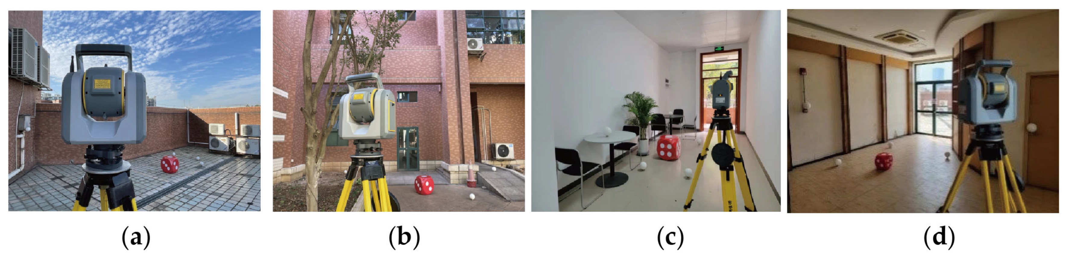
Figure 1. Scanning being performed at a tunnel segment factory in the Panyu District, Guangzhou, China: (a) scanning of a mold for the segment production; (b) scanning of the segment.
Applsci 13 01306 g001
Figure 2. Die-like furniture that can be used as the targets for the proposed registration method: (a) the round corner dice (photo taken at the Sun Yat-sen University, Guangzhou, China); (b) the sharp corner dice (photo taken at the Crosslron Mills shopping center, Calgary, Canada).
Applsci 13 01306 g002
Figure 3. Workflow of the proposed point cloud registration method.
Applsci 13 01306 g003
Figure 4. Chirality of the dice used for the proposed method.
Applsci 13 01306 g004
Figure 5. Key steps of the automatic target (die) extraction. The NDT-RANSAC is adapted for the planar feature segmentation. (a) Original point cloud. (b) NDT-RANSAC plane segmentation. (c) Extracted die.
Applsci 13 01306 g005
Figure 6. Key steps of the pips recognition for individual facets. (a) Dice plane division. (b) Rasterization and raster image convolution. (c) Raster image binarization. (d) Canny edge detection. (e) DBSCAN circle clustering.
Applsci 13 01306 g006
Figure 7. Coordinate system constructions for the die spaces. (a) Simulated axes. (b) After the axis orthogonality correction.
Applsci 13 01306 g007
Figure 8. Twenty-four constructed coordinate systems in the die space, and the transformation.
Applsci 13 01306 g008
Figure 9. Final registered coordinate systems (the west–east case).
Applsci 13 01306 g009
Figure 10. Dimensions of the die for the proposed calibration procedure.
Applsci 13 01306 g010
Figure 11. Scanning for point cloud datasets: (a) Dataset A; (b) Dataset B; (c) Dataset C; (d) Dataset D.
Applsci 13 01306 g011
Table 1. Details for the datasets collected for the registration.
DatasetsPoint CloudNO. of PointsScanner-to-Die
Distance (m)
Scan the Plane of the Dice
A1 (master)91,6286.1Pips1\2\3
2 (slave)76,7838.1Pips1\2\4
B1 (master)100,2154.5Pips1\2\3
2 (slave)114,2236.4Pips1\2\4
C1 (master)105,8672.4Pips1\4\5
2 (slave)72,2063.5Pips1\3\5
D1 (master)116,2673.2Pips1\2\3
2 (slave)123,0253.0Pips1\3\5
Table 2. RMSEs of check plane residuals before and after the registration. (Dataset A, die dimension = 50 cm × 50 cm × 50 cm).
Check PlanePoint CloudOrientApprox. Dist. From Station 1/Dice 1 (m)RMSE (mm)
Before Regist. (In Its Own Standalone Point Cloud)After Die-Based Regist. (Without Dim. Calibration)After Die-Based Regist. (With Dim. Calibration)After Spherical Target (6) Regist.
A-11 (master)Vert.11.7/5.31.75·32.01.9
2 (slave)1.4
A-21 (master)7.6/3.41.82.42.31.9
2 (slave)1.5
A-31 (master)Horiz.9/2.51.25.82.41.6
2 (slave)1.3
A-41 (master)7.7/1.81.62.61.92.0
2 (slave)1.5
Table 3. RMSEs of check plane residuals before and after the registration. (Dataset B, die dimension = 50 cm × 50 cm × 50 cm).
Check PlanePoint CloudOrientApprox. Dist. From Station 1/Dice 1 (m)RMSE (mm)
Before Regist. (In Its Own Standalone Point Cloud)After Die-Based Regist. (Without Dim. Calibration)After Die-Based Regist. (With Dim. Calibration)After Spherical Target (6) Regist.
B-11 (master)Vert.9.9/5.51.54.22.31.9
2 (slave)1.4
B-21 (master)9.1/5.31.83.12.12.2
2 (slave)1.8
B-31 (master)Horiz.6.4/1.51.23.41.81.3
2 (slave)1.2
B-41 (master)10/3.41.24.31.81.4
2 (slave)1.2
Table 4. RMSEs of check plane residuals before and after the registration. (Dataset C, die dimension = 50 cm × 50 cm × 50 cm).
Check PlanePoint CloudOrientApprox. Dist. From Station 1/Dice 1 (m)RMSE (mm)
Before Regist. (In Its Own Standalone Point Cloud)After Die-Based Regist. (Without Dim. Calibration)After Die-Based Regist. (With Dim. Calibration)After Spherical Target (6) Regist.
C-11 (master)Vert.3.2/2.41.55.82.11.7
2 (slave)0.9
C-21 (master)5.2/2.61.13.32.31.9
2 (slave)1.5
C-31 (master)Horiz.2.5/0.51.34.51.71.9
2 (slave)1.2
C-41 (master)5/1.81.23.41.61.7
2 (slave)1.5
Table 5. RMSEs of check plane residuals before and after the registration. (Dataset D, die dimension = 30 cm × 30 cm × 30 cm).
Check PlanePoint CloudOrientApprox. Dist. From Station 1/Dice 1 (m)RMSE (mm)
Before Regist. (In Its Own Standalone Point Cloud)After Die-Based Regist. (Without Dim. Calibration)After Die-Based Regist. (With Dim. Calibration)After Spherical Target (6) Regist.
D-11 (master)Vert.5.5/2.81.63.52.21.7
2 (slave)0.8
D-21 (master)3.1/1.81.52.82.42.1
2 (slave)1.2
D-31 (master)Horiz.2.9/1.21.25.51.61.7
2 (slave)1.3
D-41 (master)6.3/3.20.95.51.61.8
2 (slave)1.0
Table 6. Angles between each facet, and the average calibrated dimension of the dices.
DatasetsPoint CloudAngle between Facets (XY/XZ/YZ) (°)Original Die Side Length (m)Average Side Length after Calibration (m)
A1 (master)90.1\89.6\90.10.5000.480
2 (slave)90.4\90.3\89.5
B1 (master)90.5\90.6\90.40.5000.488
2 (slave)89.7\89.2\89.8
C1 (master)89.1\89.6\88.30.5000.489
2 (slave)90.2\89.8\89.3
D1 (master)89.1\89.6\88.30.3000.281
2 (slave)90.3\89.5\89.7
Table 7. Registered point clouds before and after the dimension calibration.
DatasetsRegistration Result (before Dim. Calibration)Registration Result (after Dim. Calibration)
AApplsci 13 01306 i001Applsci 13 01306 i002
BApplsci 13 01306 i003Applsci 13 01306 i004
CApplsci 13 01306 i005Applsci 13 01306 i006
DApplsci 13 01306 i007Applsci 13 01306 i008
Disclaimer/Publisher’s Note: The statements, opinions and data contained in all publications are solely those of the individual author(s) and contributor(s) and not of MDPI and/or the editor(s). MDPI and/or the editor(s) disclaim responsibility for any injury to people or property resulting from any ideas, methods, instructions or products referred to in the content.

