Article

FiMa-Reader: A Cost-Effective Fiducial Marker Reader System for Autonomous Mobile Robot Docking in Manufacturing Environments

1
School of Mechanical Engineering, Xi’an Jiaotong University, Xi’an 710049, China
2
Research and Development Department, Shenzhen Youibot Robotics Co., Ltd., Shenzhen 518100, China
*
Author to whom correspondence should be addressed.
These authors contributed equally to this work.
Appl. Sci. 2023, 13(24), 13079; https://doi.org/10.3390/app132413079
Submission received: 13 November 2023 / Revised: 29 November 2023 / Accepted: 4 December 2023 / Published: 7 December 2023
(This article belongs to the Special Issue Advanced Manufacturing for Industry 4.0)

Abstract

:

Featured Application

A fiducial marker reader system, featuring a novel marker design, has been proposed to guide mobile robots in accomplishing high-precision docking missions within smart factories. The implementation of this technology can provide a cost-effective and readily deployable sensor solution for automated docking in various scenarios.

Abstract

Accurately docking mobile robots to various workstations on the factory floor is a common and essential task. The existing docking methods face three major challenges: intricate deployment procedures, susceptibility to ambient lighting, and incapacity to recognize product information during the docking process. This paper devises a novel approach that combines the features of ArUco and Data Matrix to form a composite marker termed “DataMatrix-ArUco-Hybrid” (DAH). The DAH pattern serves as a fiducial marker capable of concurrently providing both target pose information and product information. Detection of the DAH pattern is conducted by a cost-effective fiducial marker reader system, called “FiMa-Reader”, which comprises an embedded processing unit and an infrared camera equipped with a 940 nm fill-light to overcome lighting issues. The FiMa-Reader system effectively detects the DAH pattern under both well-lit and dimly lit conditions. Additionally, the implementation of the FiMa-Reader system leads to significant improvements in positioning accuracy, including an 86.42% improvement on the x-axis, a 44.7% improvement on the y-axis, and an 84.21% improvement in angular orientation when compared to traditional navigation methods. The utilization of FiMa-Reader presents an economically viable system capable of guiding mobile robots’ positioning with high precision in various indoor lighting conditions.

1. Introduction

Intelligent manufacturing is a vital element of Industry 4.0, driving the advancement of autonomous mobile robot (AMR) technology [1,2]. AMRs working in factories must traverse multiple workstations or machines, position with satisfactory precision, and perform various tasks [3,4]. However, manufacturing environments are inherently dynamic due to human–robot coexistence [5,6]. To achieve successful automation tasks, AMRs require accurate and reliable positioning systems.
Despite extensive research on AMRs in recent years, achieving millimeter positioning accuracy in the absence of environmental modification remains a challenge. One solution to this challenge is to divide an AMR navigation mission into a pure navigating phase and a high-precision docking phase [5,7]. To address the docking challenge, research has focused on various target docking methods, including vision-based, laser-based, optics-based, ultrasonic-based, and other approaches.
However, these approaches face challenges related to distinguishability and maintenance costs. Distinguishability refers to the target feature being easily confused with the background, leading to failed docking processes. This problem is often encountered in laser-based, optic-based, and ultrasonic-based methods. The vision-based methods used in docking missions primarily rely on fiducial markers installed on the ground or the surface of the target. However, current fiducial markers like ArUco or AprilTag are not compatible with commonly used information codes such as Quick Response (QR) codes and DataMatrix (DM). As a result, deploying these markers incurs significant costs as each target requires the installation of at least two markers and the establishment of a mapping relationship between the fiducial markers and information codes. Additionally, the performance of existing vision-based methods is sensitive to ambient light, leading to instability in the docking process under light-on and light-off conditions.
To address these challenges, we have developed a fiducial marker reader system named FiMa-Reader, specifically designed for docking tasks. The FiMa-Reader system consists of both software and hardware modules. The hardware module comprises an embedded system, a near-infrared camera, and multiple 940nm fill-lights. On the other hand, the software module comprises the detection algorithm of a novel two-dimensional marker pattern called the DataMatrix-ArUco-Hybrid (DAH) pattern, as well as an accelerated framework for the DAH pattern detection. The main contribution of the proposed technology are as follows:
(1)
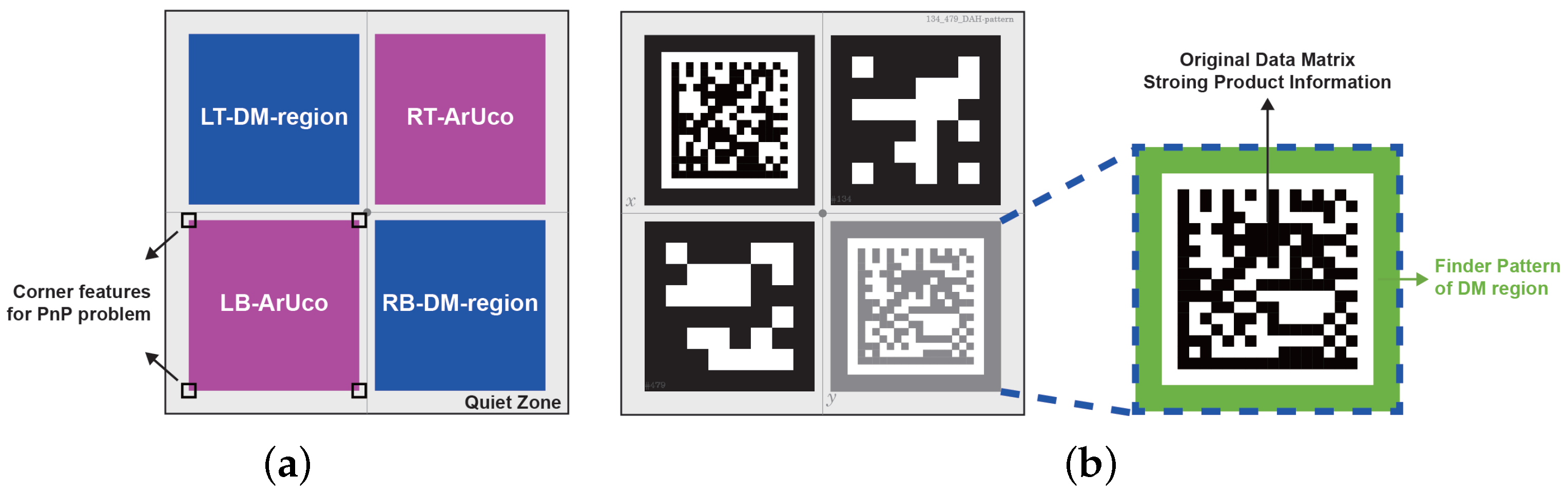
The proposed DAH pattern combines the ArUco and Data Matrix to increase information encoding capacity while maintaining simple features. The redundancy in the DAH pattern design allows it to function even in the presence of occlusion. Additionally, the composite design minimizes deployment costs as only one marker needs to be installed;
(2)
The proposed multithread acceleration framework distributes the detection tasks across multiple cores, resulting in a higher frame rate per second. This optimization maximizes the utilization of onboard resources and enables robots to dock with higher precision;
(3)
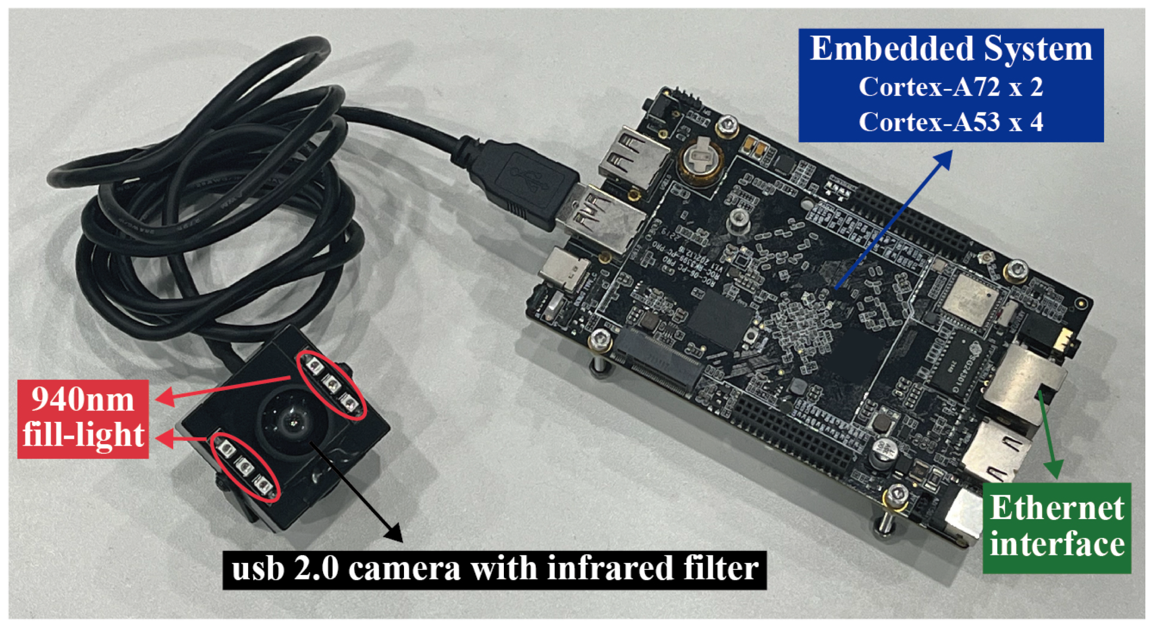
The FiMa-Reader system utilizes a near-infrared camera for detection, ensuring that ambient light does not affect the image quality. This ensures stable detection results under different indoor lighting conditions.
The remainder of this paper is organized as follows. Section 2 reviews the related work in mobile robot docking areas in recent years. Section 3 introduces the software and hardware modules in the FiMa-Reader system. Section 4 presents four experiments and analyzes the results. Finally, a conclusion is given in Section 5.

2. Related Work

AMRs with an upper device, such as a rack, roller, or lifter, are designed to pick up and deliver products between different workstations. The fundamental challenge of this task can be summarized as an indoor Simultaneous Localization and Mapping (SLAM) problem. While a considerable amount of research has been published on SLAM problems, state-of-the-art studies indicate that centimeter-level positioning can be largely solved for AMRs equipped with wheel encoders and laser scanners [8]. However, applications such as cargo delivery require AMRs to align with a roller conveyor with millimeter-level positioning precision and minute-level orientation precision, which is defined as a docking problem.
Bostelman and Hong [9] briefly defines an AMR docking problem as arriving and stopping at a position relative to another object. Docking includes positioning a mobile chassis or onboard equipment relative to another object, such as a tray station, trailer, or pallet. Docking occurs at the final stage of navigation, using various sensors to update the target location and approach the target at a relatively low speed. The literature reports several docking techniques, which can be classified according to the type of sensor used, such as camera-based [10,11,12,13], laser-based [14,15,16], and optics-based [17] sensors, among others [18,19,20].
One docking method is a laser-based technique that uses a 2D LiDAR scanner to detect specific artificial features for positioning. Commonly used features are reflectors or 3D shape blocks, which can make the docking target stand out from the background. Hercik [15] investigated different shape-based blocks used for precise AMR docking and found that L-shape blocks enable the most accuracy, with a repetitive error of ±3 mm. However, the installation position of the blocks and features such as ambient corners can significantly affect this method. A similar technique is widely used in industrial robots, such as MiR and Fetch Robotics, for charge docking. Liu [14] presented the development of a laser reflection intensity-based docking approach using reflective tape instead of a block installed on the charging station. The experiment showed that the proposed method had significantly higher success rates than a shape-based technique in unstructured environments. Reflective tape is also more accessible to deploy than 3D shape blocks.
While a 2D LiDAR scanner is commonly used in docking methods, it may not be effective in actual industrial environments where workstation surface materials have a reflection intensity similar to reflective tape, leading to imprecise docking target detection. To address this challenge, several studies have attempted to use a LiDAR scanner for precise indoor localization without environmental modification. The fundamental idea of these techniques is to improve the point cloud registration method accuracy, such as the iterative closest point (ICP) method [16,21]. The improved ICP approach meets the sub-centimeter precision demand. However, there has been no detailed analysis of the effect of dynamic elements on position accuracy, which is common in industrial scenarios due to product delivery and frequent worker movement.
A camera, compared to a 2D LiDAR scanner, is more cost-effective and has higher information density. Previous studies have focused extensively on vision-based docking methods, with Quick Response (QR) codes and fiducial markers such as ArUco [22] or AprilTag [23] being widely used as visual landmarks to guide an AMR in docking tasks. Visual landmarks can be installed on the ground or side. In ground applications, a camera observes the landmarks from a parallel perspective. The detection algorithm needs to locate the landmark center point and its rotation around the z-axis, and it is possible to transform coordinates expressed in pixel coordinates to length coordinates using a pixel-to-meter ratio [12,24]. However, industrial ground surface landmarks require frequent maintenance due to scratches or damage caused by worker movement and the contamination of production materials.
Installing landmarks on a target surface rather than on the ground in front of the target can significantly reduce maintenance costs and increase flexibility since they do not require frequent readjustment when the target position changes. Side-mounted landmarks provide 6-DoF pose information that indicates the relative pose between the landmarks and robots. A general approach finds the landmark’s corner point in both pixel and world coordinates, converting the problem into a classical perspective-n-point (PnP) problem. The PnP problem output is the landmark’s pose relative to the camera coordinates, and calibration can obtain the extrinsic parameters between the camera and AMR, considering that they are rigidly connected. Tian [25] utilized ArUco recognition technology for navigation and positioning in visually guided electric assistive devices, with the results showing that vision guidance is stable, accurate, and low-cost. Wang [11] proposed an EKF-based relative pose estimation algorithm to handle polluted and intermittently available visual measurements of fiducial markers. In a similar substation application, Wang [26] used ArUco on both the ground and wall, with each ArUco marker on the ground fused into a map as a specific landmark and each wall ArUco indicating the charging station location. Vision-based docking methods are also utilized in underwater environments [27,28] and drone landings [29].
Despite the high accuracy and easy deployment of vision-based docking methods, they are sensitive to ambient light conditions. To address the problem of drastic illumination changes caused by sunlight, Nowara [30] proposed using narrow-bandwidth near-infrared active illumination at 940 nm coupled with a matching bandpass filter on the camera, which significantly reduced variations in ambient light, making the image quality stable and consistent regardless of lighting conditions. However, there has been little research on the use of near-infrared cameras in industrial AMR docking processes. Most studies on near-infrared cameras applications in robotics have focused on using infrared LEDs as landmarks to guide robots in navigation, landing, or gripping tasks [31,32].

3. Proposed System

3.1. Software Module

3.1.1. Definition of DataMatrix-ArUco-Hybrid Pattern

Fiducial markers commonly used for docking, such as ARToolKit, AprilTag, and ArUco, are typically limited to encoding numbers only [33]. However, there are many docking targets in manufacturing factories with similar characteristics, requiring a secondary validation process to confirm the actual string content of target workstations or devices before executing the subsequent action.
To address this issue, we propose a new 2D fiducial marker pattern called the DataMatrix-ArUco-Hybrid (DAH) pattern, consisting of four inner markers—two ArUco and two Data Matrix (DM)—in a diagonal form. The clockwise order of the inner markers in the DAH pattern is left-top DM (LT-DM-region), right-top ArUco (RT-ArUco), right-bottom DM (RB-DM-region), and left-bottom ArUco (LB-ArUco), as shown in Figure 1.
To locate the DM candidates in an image quickly, we defined a homocentric square surrounding the original DM as the DAH pattern finder pattern, as shown in the green area in Figure 1b. The region enclosed by the largest outer square in the homocentric square is called a DM region, which is represented by the blue area in Figure 1a. Each valid DAH pattern contains at most two DM regions, with each DM region containing at most one DM. The two DM regions in a DAH pattern are distinguished by the first symbol in the encoded content. We defined the first symbol of the LT-DM-region content as % and the first symbol of the RB-DM-region content as &.
To determine the suitable RT-ArUco and LB-ArUco IDs in the generation process, we developed a rule to map the input production information to a valid number in the chosen ArUco dictionary. First, we use the CRC32 hash algorithm to map the input string content to an integer N. Assuming the RT-ArUco ID is a and the LB-ArUco ID is b, if the chosen dictionary’s maximum number is K, then the inner ArUco IDs a and b are, respectively, defined as the remainder of N to K and the remainder of N to K 1 ; a calculation example is illustrated in Figure 1b.
By calculating the two ArUco IDs, all inner markers in a DAH pattern can be defined, which can help the detection algorithm find the correct ArUco ID to combine with a DM region candidate to form a valid DAH pattern.

3.1.2. Detection Framework of DataMatrix-ArUco-Hybrid Pattern

In this section, we introduce the DAH pattern detection framework, which comprises five modules: preprocessing, contour filter, perspective transformation, decoder, and DAH pattern combination. Each module takes the output from the preceding module as input and generates a result, as shown in Figure 2.
The first process is the preprocessing module, which functions similarly to the operations in the ArUco detection library [22]. The output from the preprocessing module contains the pixel points on each contour, the centroid of each contour, and the hierarchical relationship between each contour.
The contour filtering process involves two traversals. In the first traversal, we mark the contours without internal contours as invalid regions because the DM and ArUco regions must have internal contours. According to the design rules, a set of contours with a close centroid is likely to be a DM region. If all contours in the set satisfy the conditions of being convex quadrilaterals and the size of the set is more than two but less than four, we mark these contours as processed. The largest area contour in the set is marked as a candidate DM region and is saved to the set. Each new DM region added to the DM region set must be compared to the existing regions. If the two regions being compared satisfy the following conditions:
(a)
The contents of the two DM regions are identical except for the first symbol;
(b)
The distance between the two DM region centroids is within x times the side length of the current new DM region, and the x chosen here is between 1.5 and 2.0, we mark the two DM regions that satisfy the above two conditions as a “friend DM region” of the other. This is useful in the DAH pattern combination module.
In the second traversal, we focus only on the remaining unprocessed contours. We mark those that can be approximated to convex quadrilaterals as ArUco regions and add them to the ArUco region set. The DM and ArUco regions undergo a preliminary filtering step, which removes regions that are too close to the image boundaries, as well as the smaller of two regions that are in proximity to each other.
Each filtered region undergoes perspective transformation to produce a canonical region, which yields a higher decoding success rate. We use the idea from previous ArUco studies to perform the transformation in a different image pyramid layer according to the region size rather than all in the original image. The following process is the decoding module, which aims to extract the encoded content from the canonical DM regions and extract the IDs from the canonical ArUco regions. We use the ZXing library for DM region decoding and the ArUco dictionary definition for ArUco region decoding.
After the decode module, all regions remaining in the set are valid regions. The final step of the detection algorithm is to integrate different regions to form a proper DAH pattern region. The DAH pattern combination algorithm is presented in Algorithm 1. The core idea of Algorithm 1 is to use each DM region as an anchor region, bind its friend DM region, and compare it with all unprocessed ArUco regions. We bind the ArUco region and current anchor DM region if the ArUco region satisfies the following conditions:
(a)
The ArUco ID and the content of the current DM region satisfy the mapping relationship introduced in Section 3.1.1;
(b)
The distance between the ArUco centroid and the DM centroid is within x times the side length of the DM region, and the x chosen here is between 0.7 and 1.5.
The satisfied ArUco and DM regions are stored in a temporary DAH pattern. If the inner marker number of the temporary DAH pattern is more than two, we save the temporary DAH pattern in a temporary DAH pattern set. For each traversal, the current DM region, its friend DM region, and its binding ArUco regions are marked as processed.
After all DM regions are traversed, the temporary DAH pattern set contains several DAH pattern candidates. Only the DAH pattern that satisfies the following conditions will be accepted: it must contain at least one DM region and one ArUco region, and these two regions must not be located diagonally from each other. We exclude those invalid DAH patterns and output the filtered set as the detection result.

3.1.3. Multithread Processing Framework for Acceleration

Previous fiducial marker application studies have mostly relied on single-thread frameworks. However, this approach can be detrimental to algorithm detection speed and fail to maximize the processing unit’s computational resources in cost-sensitive embedded systems. To address this issue, we propose a multithread framework for DAH pattern detection, as shown in Figure 3. We implement a thread pool for parallel processing of different frames and an image state hash table to manage each frame’s current status. Each frame can have one of three statuses: processing (state 0), finished processing with a valid pose (state 1), or finished processing with an invalid pose (state −1).
Algorithm 1: Integrate region to DAH pattern.
Applsci 13 13079 i001
When a new frame is input from the camera, a task is submitted to the thread pool. The detection process, as described in Section 3.1.2, is executed for the first time. Once the detection process is complete, the current task obtains a set of DAH pattern regions. Using the coordinates of the DAH pattern region corners in the world and pixel coordinate systems, a PnP problem solver calculates the camera pose. We use an infinitesimal plane-based pose estimation (IPPE) [34] solver for this purpose, and the IPPE result is saved temporarily.
To ensure that the output queue order is the same as the input queue, the current task in the thread pool must wait until the last task in the thread pool exits. The image state hash table allows for this waiting mechanism. Each time the current thread is awakened by another thread notification, the current state of the last frame is queried, and the hibernation is stopped if the status is not zero.
To overcome the ambiguous fiducial marker problem, we use the last frame pose to constrain the current frame pose, which is inspired by ArUco. If the last frame pose is valid, the task discards the IPPE pose result calculated before, and the last stamp pose is refined using the Levenberg–Marquarelt (LM) algorithm as the initial value. If the last frame pose is invalid, the IPPE pose result is used for the refined process as the initial value. The optimization objective in the LM algorithm is to minimize the reprojection error of all four corner points of the DAH pattern in the current frame whether the source of the initial value is the IPPE result or the last frame.
When the current thread exits, regardless of the exit phase, it must update the current stamp state on the image state hash table. If the current thread exits after notification, which means the last stamp is useless in the hash table, it must also erase the last stamp date from the hash table. Our proposed multithread framework can accelerate the DAH pattern detection process and effectively utilize computational resources in an embedded system.

3.2. Hardware Modules

The embedded system utilizes an infrared camera as the primary data sensor, and 940 nm wavelength infrared fill-lights are installed in proximity to the camera to ensure sufficient captured-image brightness. The embedded system processor adopts a big.LITTLE framework, comprising two Cortex-A72 cores and four Cortex-A53 cores. The system operates on a Linux platform and transmits results information through an Ethernet interface, as shown in Figure 4.

4. Experiments and Analysis

Following the description of the proposed FiMa-Reader system, we move over to the experiments. The experiments are divided into four parts, each focusing on different aspects related to the proposed solution. First, we investigate the performance of the proposed DAH pattern, as described in Section 3.1.1. Second, we compare the repeatable docking process positioning accuracy using the FiMa-Reader system and a LiDAR-based navigation process. Third, we compare the position accuracy of different FiMa-Reader system output rates to validate the effectiveness of the multithread framework described in Section 3.1.3. Finally, we test the performance of the FiMa-Reader system in both light-on and light-off scenarios to validate the proposed infrared camera and 940nm fill-lights. For each experiment, we describe how it was conducted and the obtained results. Finally, we provide comments on the obtained results.

4.1. Experiment 1: DAH Pattern Performance

The first experiment investigates the viability of the proposed DAH pattern. In order to assess its effectiveness, we conducted a performance comparison between the proposed DAH pattern and the extensively employed fiducial marker. Noteworthy examples of fiducial markers commonly applied in practical scenarios encompass AprilTag, ArUco, DM codes, and QR codes.
ArUco and AprilTag are both variants of ARTag, sharing identical pattern designs and appearances. ArUco also supports the AprilTag dictionary. The differences between them lie in image preprocessing and candidate region search methods. Compared to AprilTag, ArUco exhibits significantly faster detection and decoding speeds, a crucial metric for real-time calculations on embedded platforms. Hence, we consider AprilTag and ArUco as equivalent, with ArUco being the superior choice. This is the reason we selected ArUco as a comparative option.
Similarly, QR codes and DM codes are both traditional codes used for storing substantial information. The only difference lies in the Finder pattern. QR codes have three concentric rectangles as their Finder pattern, while DM codes have an L-shaped Finder pattern. This means DM codes can accommodate more valid information in a smaller area, which is one reason we chose DM codes as a control group. Another reason is that in open-source detection algorithms, DM codes consistently exhibit better recognition accuracy than QR codes.
Building upon the aforementioned deliberations, we have selected ArUco, DM codes, and a pattern wherein the DM is enveloped by a homocentric square (referred to as the DM with Box) as the designated control groups. All markers were same size of 50 mm and the same surface material was used for printing. We employed the ArUco library (https://sourceforge.net/projects/aruco/files/, accessed on 22 October 2022) to detect the ArUco marker, and the ZXing library (https://github.com/glassechidna/zxing-cpp, accessed on 22 October 2022) to detect the DM. For the DM with the Box pattern, we used the framework described in Section 3.1.2 for detection, with the difference being that DM with Box pattern detection did not require detecting the ArUco and integrating the region into the DAH pattern.
We created four different backgrounds to simulate the markers placed on different surfaces: clean, cage-like textured, line textured, and usual indoor background, as shown in Figure 5. For each background, we captured 25 images of each marker at different distances and angles. The hardware settings in all the following experiments are illustrated in Section 3.2. Considering the effective light range of the infrared fill-light, the maximum distance between the camera and marker was approximately 250 mm, while the minimum distance was approximately 50 mm. We also created random occlusion images from the original images by generating ten random circles within the manually labeled ROI for each original image, an occlusion image example can be found in Figure 5e–h.
To evaluate the detection performance in the experiment, we used three metrics: the data capacity, detection rate, and average detection time. As all images in the dataset included one valid marker, the images in which no valid marker was found were considered failed detections, while those in which a valid marker was found were considered successful detections. The detection rate was calculated by dividing the number of successful image detections by the total number of images.
Table 1 summarizes the results of the first experiment. We observed that compared to the ArUco, the marker including the DM has a larger data capacity. In the original image dataset, the DAH pattern showed the highest detection rate and detection time compared to the other markers. In particular, the DAH pattern significantly outperformed the ArUco, DM, and DM with Box in terms of detection rate, demonstrating that the DAH pattern is more robust and reliable than any of the individual markers in actual industrial environments.

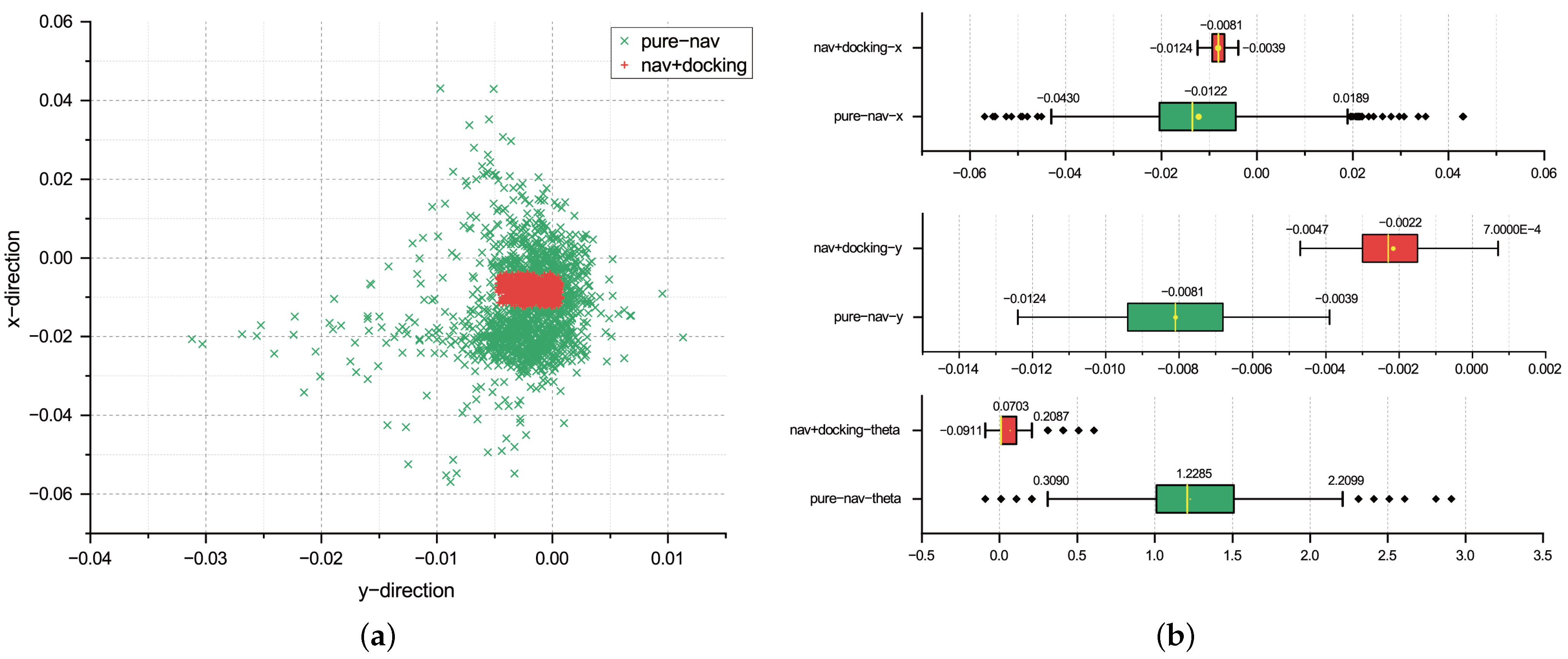
4.2. Experiment 2: FiMa-Reader System Positioning Accuracy

In the second experiment, we evaluated the positioning accuracy of an autonomous mobile robot (AMR) equipped with the proposed FiMa-Reader system. The AMR used in this experiment, shown in Figure 6a, is called the Trans and features a differential mobile chassis with two 2D LiDARs mounted on opposite corners. It uses wheel encoders and an IMU for odometry and a 2D LiDAR point cloud for observation to navigate. To evaluate the position accuracy, we used a PGV100 Pepperl-Fuchs sensor to record the relative position between a DM placed on the ground and the PGV100, which has a measurement resolution of 0.1 mm and 0.1 degrees. We installed the FiMa-Reader system and the PGV100 on top of the Trans.
As shown in Figure 6b, we conducted two independent missions for the Trans: one for pure navigation and the other for navigation with docking. Both missions had the same navigation goal. In the pure navigation process, we used only LiDAR and odometry to determine the robot’s position. In the docking process, the FiMa-Reader system outputted the relative pose between the DAH pattern and the Trans and transmitted this information to the chassis to update the robot self-localization. When the chassis determined that the current position was close enough to the navigation goal, the mission was completed, and the PGV100 recorded the current relative pose according to the DM placed on the ground. After each mission was completed, the chassis returned to the navigation starting point and repeated each task 1500 times.
Figure 7 illustrates the positioning distribution of the pure navigation task and the navigation with docking task. Figure 7a shows the x-y distribution of the two tasks, with a green “x” representing the completed positions of the pure navigation task and a red “+” representing the positions of the navigation with docking task. The group of red points is significantly more centralized than the green points, indicating that the navigation with docking task has a more precise positioning ability. Figure 7b shows the x-direction, y-direction and theta angle position distributions, respectively. The x range of the docking process is 8.4 mm, while the x range of the pure navigation is 61.9 mm. Using the FiMa-Reader system improved the accuracy by 86.42%. The y range of the docking process is 4.7 mm, while the y range of the pure navigation is 8.5 mm, with the FiMa-Reader system improving the accuracy by 44.7%. The theta angle of the docking process is 0.30 degrees, while the theta angle of pure navigation is 1.9 degrees, with the FiMa-Reader system improving the accuracy by 84.21%.

4.3. Experiment 3: Positioning Accuracy of Different FiMa-Reader System Output Rates

In this experiment, we aimed to determine the positioning accuracy of different FiMa-Reader system output rates to verify the effectiveness of the multithread framework described in Section 3.1.3. We used the same scenario as in Experiment 2, and the mission was navigated with docking, with the navigation target and DAH pattern placement remaining the same throughout all experiments. We tested three frame rates in this experiment: 15 Hz, 30 Hz, and 60 Hz. Different output frame rates were achieved by adjusting the camera capture rate. Each rate experiment was repeated 500 times, and the evaluation metric was the PGV100 position when the mission was completed.
Figure 8 illustrates the positioning accuracy of the FiMa-Reader system at 15 Hz, 30 Hz, and 60 Hz output frame rates. The box lengths of the different rates are close to each other, indicating that the docking process relies not only on the FiMa-Reader system but also on wheel encoders and an IMU for dead reckoning, which are highly accurate at short distances. However, the data range decreases as the frame rate increases, indicating that a higher observation rate can reduce the positioning deviation. This is because the Trans can update its position at a higher rate to determine whether it has arrived at the navigation target.

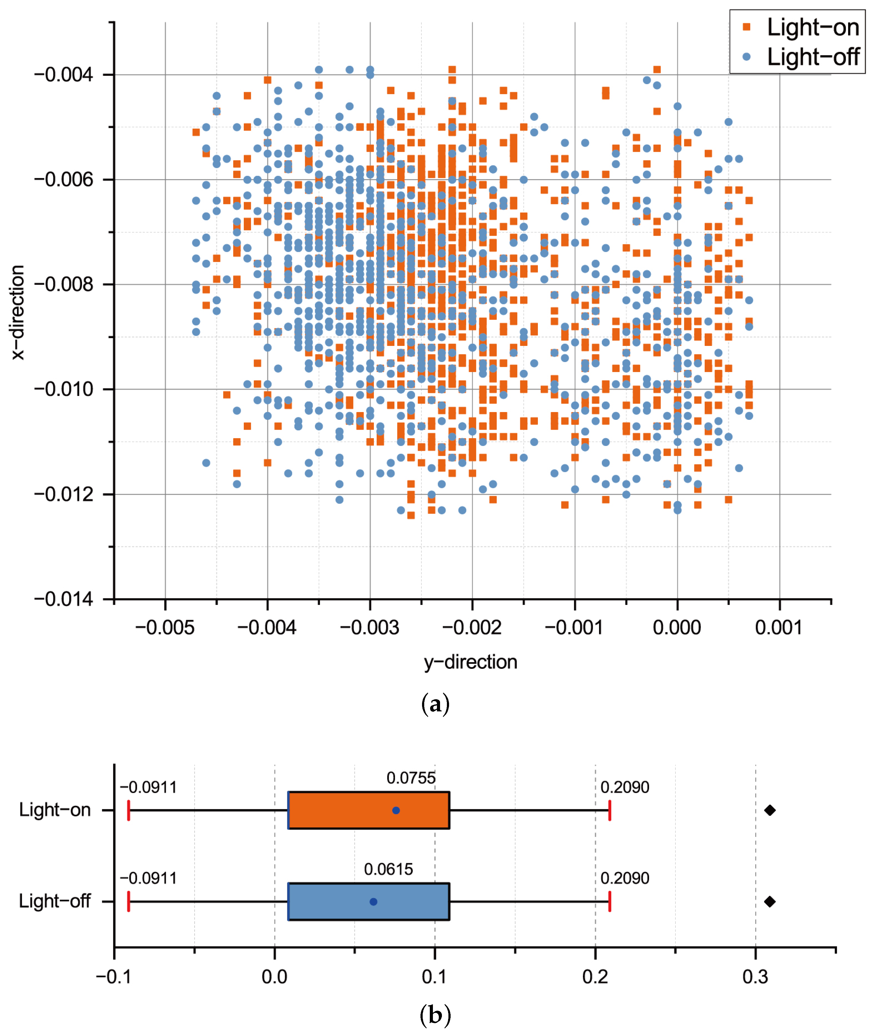
4.4. Experiment 4: Positioning Accuracy of the Light-On and Light-Off Scenarios

The final experiment aimed to determine whether the FiMa-Reader system could overcome the influence of ambient light. We designed the same navigation with docking tasks as in Experiment 3, with a frame rate of 60 Hz, and conducted the tasks in both a light-on indoor environment and a light-off indoor environment. Each experiment was repeated 500 times. In the light-off environment, hardly any visible light could be seen, which would definitely result in different image quality compared to the light-on environment in a usual RGB camera.
Figure 9 illustrates the positioning results from the two scenarios, with orange points representing the results from the light-on condition and blue points representing the results from the light-off condition. The x, y, and theta distributions are almost consistent, indicating that the proposed FiMa-Reader system can work effectively in both light-on and light-off manufacturing applications.

5. Conclusions

In this paper, we proposed a fiducial marker reader system called the FiMa-Reader system, which consists of a novel marker pattern, the DAH pattern, a low-cost embedded system, and MVI computer software version 1.0. The proposed DAH pattern combines two Data Matrix and two ArUco markers to form a new pattern that has a larger data capacity and more robust detection for occlusion situations. The embedded system uses an infrared camera and 940 nm fill-lights to overcome the influence of ambient light.
This paper also proposes a framework for DAH pattern detection. To improve the DAH pattern observation rate for a smoother and more precise docking process, a multithread framework used for acceleration was proposed. The framework uses a thread pool to execute the preprocessing of each frame in parallel. The experimental results show that the DAH pattern outperforms a single ArUco or a single Data Matrix pattern in terms of detection rate and detection time. Using the FiMa-Reader system for the docking process can significantly improve the positioning accuracy compared to pure navigation. Furthermore, the FiMa-Reader system is not affected by ambient light, which means it can work during the day or night and output consistent high-precision observations.
The proposed system still has certain limitations. For instance, at long distances, the detection rate may decrease due to the diminutive size of each submarker within the DAH pattern. Additionally, the existing rules only support mutual mapping between DM codes and ArUco, resulting in less scalability. Lastly, our multithreaded framework assumes the input from a single camera source at any given time, limiting the system’s capability to handle multiple cameras simultaneously. Our future work will focus on improving the detection rate of the DAH pattern at long distances and supporting the simultaneous processing of multiple cameras in the multithreaded framework.

Author Contributions

X.B. and W.C. developed the original concept of this paper and designed the system framework. W.C. conducted the experiments and drafted the manuscript. D.R. and Z.L. contributed to the data collection process. X.M. reviewed the manuscript and supervised the project. All authors have read and approved the final version of the manuscript.

Funding

This work was funded by Key Research and Development Program of Shaanxi (Program No. 2021ZDLGY09-03) and National Key Research and Development Plan (No. 2019YFB1707503HZ-03).

Institutional Review Board Statement

Not applicable.

Informed Consent Statement

Not applicable.

Data Availability Statement

The code used in this study and datasets from Experiment 1 (DAH pattern performance) are available from the corresponding author upon reasonable request. The data are not publicly available due to the code and the datasets contain other commercially protected content unrelated to the methods mentioned in this paper, such as hardware drivers, software frameworks, and background and methods during data collection. This content can only be obtained for non-commercial purposes and after signing a confidentiality agreement with Shenzhen Youibot Robotics Co., Ltd. (Shenzhen, China).

Conflicts of Interest

Authors Wenzhao Chen, Donglai Ran and Zhimou Liang were employed by the company Shenzhen Youibot Robotics Co., Ltd. The remaining authors declare that the research was conducted in the absence of any commercial or financial relationships that could be construed as a potential conflict of interest.

References

  1. Fasuludeen Kunju, F.K.; Naveed, N.; Anwar, M.N.; Ul Haq, M.I. Production and maintenance in industries: Impact of industry 4.0. Ind. Robot. Int. J. Robot. Res. Appl. 2022, 49, 461–475. [Google Scholar] [CrossRef]
  2. Brecher, C.; Müller, A.; Dassen, Y.; Storms, S. Automation technology as a key component of the Industry 4.0 production development path. Int. J. Adv. Manuf. Technol. 2021, 117, 2287–2295. [Google Scholar] [CrossRef]
  3. Fragapane, G.; Ivanov, D.; Peron, M.; Sgarbossa, F.; Strandhagen, J.O. Increasing flexibility and productivity in Industry 4.0 production networks with autonomous mobile robots and smart intralogistics. Ann. Oper. Res. 2022, 308, 125–143. [Google Scholar] [CrossRef]
  4. Chang, C.Y.; Wu, C.L.; Cheng, J.M.; Jian, S.J. Autonomous mobile robots for recycling metal shaving at CNC factories. Int. J. Adv. Manuf. Technol. 2023, 126, 2205–2218. [Google Scholar] [CrossRef]
  5. Savci, I.H.; Yilmaz, A.; Karaman, S.; Ocakli, H.; Temeltas, H. Improving navigation stack of a ros-enabled industrial autonomous mobile robot (amr) to be incorporated in a large-scale automotive production. Int. J. Adv. Manuf. Technol. 2022, 120, 3647–3668. [Google Scholar] [CrossRef]
  6. Grau, A.; Indri, M.; Bello, L.L.; Sauter, T. Robots in industry: The past, present, and future of a growing collaboration with humans. IEEE Ind. Electron. Mag. 2020, 15, 50–61. [Google Scholar] [CrossRef]
  7. Nejat, G.; Benhabib, B. Modelless guidance for the docking of autonomous vehicles. IEEE Trans. Robot. 2007, 23, 753–762. [Google Scholar] [CrossRef]
  8. Cadena, C.; Carlone, L.; Carrillo, H.; Latif, Y.; Scaramuzza, D.; Neira, J.; Reid, I.; Leonard, J.J. Past, present, and future of simultaneous localization and mapping: Toward the robust-perception age. IEEE Trans. Robot. 2016, 32, 1309–1332. [Google Scholar] [CrossRef]
  9. Bostelman, R.; Bostelman, R.; Hong, T. Review of Research for Docking Automatic Guided Vehicles and Mobile Robots; US Department of Commerce—National Institute of Standards and Technology: Gaithersburg, MD, USA, 2016. [Google Scholar]
  10. Vukolov, A.; Kourousias, G.; Pugliese, R. Flexible vision-based auto-docking control system for unmanned ground vehicles equipped with differential chassis. In Proceedings of the International Conference on Robotics in Alpe-Adria Danube Region, Klagenfurt am Wörthersee, Austria, 8–10 June 2022; pp. 403–411. [Google Scholar]
  11. Wang, Y.; Shan, M.; Yue, Y.; Wang, D. Autonomous target docking of nonholonomic mobile robots using relative pose measurements. IEEE Trans. Ind. Electron. 2020, 68, 7233–7243. [Google Scholar] [CrossRef]
  12. Bolanakis, G.; Nanos, K.; Papadopoulos, E. A QR Code-based High-Precision Docking System for Mobile Robots Exhibiting Submillimeter Accuracy. In Proceedings of the 2021 IEEE/ASME International Conference on Advanced Intelligent Mechatronics (AIM), Delft, The Netherlands, 12–16 July 2021; pp. 830–835. [Google Scholar]
  13. Tsiogas, E.; Kleitsiotis, I.; Kostavelis, I.; Kargakos, A.; Giakoumis, D.; Bosch-Jorge, M.; Ros, R.J.; Tarazón, R.L.; Likothanassis, S.; Tzovaras, D. Pallet detection and docking strategy for autonomous pallet truck agv operation. In Proceedings of the 2021 IEEE/RSJ International Conference on Intelligent Robots and Systems (IROS), Prague, Czech Republic, 27 September–1 October 2021; pp. 3444–3451. [Google Scholar]
  14. Liu, Y. A laser intensity based autonomous docking approach for mobile robot recharging in unstructured environments. IEEE Access 2022, 10, 71165–71176. [Google Scholar] [CrossRef]
  15. Hercik, R.; Byrtus, R.; Jaros, R.; Koziorek, J. Implementation of autonomous mobile robot in smartfactory. Appl. Sci. 2022, 12, 8912. [Google Scholar] [CrossRef]
  16. Yilmaz, A.; Sumer, E.; Temeltas, H. A precise scan matching based localization method for an autonomously guided vehicle in smart factories. Robot. Comput. Integr. Manuf. 2022, 75, 102302. [Google Scholar] [CrossRef]
  17. Wu, X.; Lou, P.; Shen, K.; Peng, G.; Tang, D. Precise transhippment control of an automated magnetic-guided vehicle using optics positioning. Int. J. Smart Sens. Intell. Syst. 2014, 7, 48–71. [Google Scholar] [CrossRef]
  18. Su, S.; Zeng, X.; Song, S.; Lin, M.; Dai, H.; Yang, W.; Hu, C. Positioning accuracy improvement of automated guided vehicles based on a novel magnetic tracking approach. IEEE Intell. Transp. Syst. Mag. 2018, 12, 138–148. [Google Scholar] [CrossRef]
  19. Falkowski, P.; Smater, M.; Koper, J.; Myśliwiec, A.; Mackiewicz, T. An Approach towards high-precision docking of the mobile robots for industrial purposes. In Proceedings of the Conference on Automation, Paris, France, 31 May–31 August 2020; pp. 239–247. [Google Scholar]
  20. Liu, H.; Zhu, W.; Ke, Y. Pose alignment of aircraft structures with distance sensors and CCD cameras. Robot. Comput. Integr. Manuf. 2017, 48, 30–38. [Google Scholar] [CrossRef]
  21. Vasiljević, G.; Miklić, D.; Draganjac, I.; Kovačić, Z.; Lista, P. High-accuracy vehicle localization for autonomous warehousing. Robot. Comput. Integr. Manuf. 2016, 42, 1–16. [Google Scholar] [CrossRef]
  22. Romero-Ramirez, F.J.; Muñoz-Salinas, R.; Medina-Carnicer, R. Speeded up detection of squared fiducial markers. Image Vis. Comput. 2018, 76, 38–47. [Google Scholar] [CrossRef]
  23. Wang, J.; Olson, E. AprilTag 2: Efficient and robust fiducial detection. In Proceedings of the 2016 IEEE/RSJ International Conference on Intelligent Robots and Systems (IROS), Daejeon, Republic of Korea, 9–14 October 2016; pp. 4193–4198. [Google Scholar]
  24. Zhang, H.; Zhang, C.; Yang, W.; Chen, C.Y. Localization and navigation using QR code for mobile robot in indoor environment. In Proceedings of the 2015 IEEE International Conference on Robotics and Biomimetics (ROBIO), Zhuhai, China, 6–9 December 2015; pp. 2501–2506. [Google Scholar]
  25. Tian, W.; Chen, D.; Yang, Z.; Yin, H. The application of navigation technology for the medical assistive devices based on Aruco recognition technology. In Proceedings of the 2020 IEEE/RSJ International Conference on Intelligent Robots and Systems (IROS), Las Vegas, NV, USA, 24 October–24 January 2021; pp. 2894–2899. [Google Scholar]
  26. Wang, C.; Yin, L.; Zhao, Q.; Wang, W.; Li, C.; Luo, B. An intelligent robot for indoor substation inspection. Ind. Robot. Int. J. Robot. Res. Appl. 2020, 47, 705–712. [Google Scholar] [CrossRef]
  27. Dong, H.; Wu, Z.; Wang, J.; Chen, D.; Tan, M.; Yu, J. Implementation of autonomous docking and charging for a supporting robotic fish. IEEE Trans. Ind. Electron. 2022, 70, 7023–7031. [Google Scholar] [CrossRef]
  28. Xu, Z.; Haroutunian, M.; Murphy, A.J.; Neasham, J.; Norman, R. An underwater visual navigation method based on multiple ArUco markers. J. Mar. Sci. Eng. 2021, 9, 1432. [Google Scholar] [CrossRef]
  29. Jin, S.; Zhang, J.; Shen, L.; Li, T. On-board vision autonomous landing techniques for quadrotor: A survey. In Proceedings of the 2016 35th Chinese Control Conference (CCC), Chengdu, China, 27–29 July 2016; pp. 10284–10289. [Google Scholar]
  30. Magdalena Nowara, E.; Marks, T.K.; Mansour, H.; Veeraraghavan, A. SparsePPG: Towards driver monitoring using camera-based vital signs estimation in near-infrared. In Proceedings of the IEEE Conference on Computer Vision and Pattern Recognition Workshops, Salt Lake City, UT, USA, 18–22 June 2018; pp. 1272–1281. [Google Scholar]
  31. Ghadiok, V.; Goldin, J.; Ren, W. On the design and development of attitude stabilization, vision-based navigation, and aerial gripping for a low-cost quadrotor. Auton. Robot. 2012, 33, 41–68. [Google Scholar] [CrossRef]
  32. Hijikata, S.; Terabayashi, K.; Umeda, K. A simple indoor self-localization system using infrared LEDs. In Proceedings of the 2009 Sixth International Conference on Networked Sensing Systems (INSS), Pittsburgh, PA, USA, 17–19 June 2009; pp. 1–7. [Google Scholar]
  33. Michail, K.; Cain, B.; Carroll, S.; Anand, A.; Camden, W.; Nikolaos, V. Fiducial Markers for Pose Estimation. J. Intell. Robot. Syst. 2021, 101, 71. [Google Scholar]
  34. Collins, T.; Bartoli, A. Infinitesimal plane-based pose estimation. Int. J. Comput. Vis. 2014, 109, 252–286. [Google Scholar] [CrossRef]
Figure 1. (a) The area definition in the DAH pattern. (b) An example of a DAH pattern: The desired encoded content of this DAH pattern is “DAH-pattern”; the corresponding decimal number obtained using the CRC32 is 1166492279. The chosen ArUco dictionary is TAG36h10, with the chosen value of K being 2023. The RT-ArUco ID is defined as 134, while the LB-ArUco ID is defined as 479. The LT-DM-region content is defined as “%DAH-pattern”, while the RB-DM region is defined as “&DAH-pattern”.
Applsci 13 13079 g001
Figure 2. The detection framework of DAH pattern.
Applsci 13 13079 g002
Figure 3. The multithread DAH pattern detection processing framework.
Applsci 13 13079 g003
Figure 4. The hardware design of the FiMa-Reader system.
Applsci 13 13079 g004
Figure 5. The origin and occlusion image dataset of the four different markers: the markers in (a) are the DAH pattern, Data Matrix, Data Matrix with Box, and ArUco in clockwise order, starting from the top left one. (a,d) are the original images. (eh) are random occlusion images. (a,e): clean background. (b,f): cage-like textured background. (c,g): line texture background. (d,h): usual indoor background. The red circles in (eh) represent randomly generated occlusion features by the computer.
Applsci 13 13079 g005
Figure 6. Experimental setup. (a) The Trans experimental AMR. (b) The experimental scenarios simulating an industrial environment, human–robot coexistence and highly dynamic environment.
Applsci 13 13079 g006
Figure 7. The repeatable positioning accuracy of pure navigation and navigation with docking using the FiMa-Reader system. (a) The x-y distribution of the Trans position locations. (b)-top: The x-direction positioning accuracy distribution, unit mm. (b)-middle: The y- direction positioning accuracy distribution, unit mm. (b)-bottom: The theta position accuracy distribution, unit degrees.
Applsci 13 13079 g007
Figure 8. The positioning accuracy of different FiMa-Reader output frame rates. (a) The x-direction positioning accuracy distribution, unit mm. (b) The y-direction positioning accuracy distribution, unit mm. (c) The theta position accuracy distribution, unit degrees. The blue dots represent the mean value, while the black squares indicate the presence of outliers.
Applsci 13 13079 g008
Figure 9. The positioning accuracy of the light-on and light-off scenarios. (a) The x-y positioning accuracy distribution, unit mm. (b) The theta position accuracy distribution, unit degrees. The blue dots represent the mean value, while the black squares indicate the presence of outliers.
Applsci 13 13079 g009
Table 1. Comparison of the data capacity, detection rate, and average detection time of the DAH pattern, ArUco, DM, and DM with Box in the original and occlusion image datasets.
Fiducial MarkerData CapacityOrigin (100 per Group)Occlusion (1000 per Group)
Detection RateAverage (Success)
Detection Time (ms)
Detection RateAverage (Success)
Detection Time (ms)
DAH patternmaximum 1556
bytes (ECC200)
97%11.0667.3%23.56
ArUcoorigin dictionary
size: 1000 ids
70%24.584.5%27.61
Data Matrixmaximum 1556
bytes (ECC200)
19%14.010.2%44.56
Data Matrix with Boxmaximum 1556
bytes (ECC200)
84%12.057.2%20.28
Disclaimer/Publisher’s Note: The statements, opinions and data contained in all publications are solely those of the individual author(s) and contributor(s) and not of MDPI and/or the editor(s). MDPI and/or the editor(s) disclaim responsibility for any injury to people or property resulting from any ideas, methods, instructions or products referred to in the content.

