Simplified Calculation Method for Active Anti-Floating of Elliptical Basements by Relief Wells
Abstract
1. Introduction
2. Simplified Calculation of Multi-Well System for Elliptical Pit
2.1. Basic Assumptions of Simplified Calculations
- Owing to the function of the cut-off wall, the water inflow of drainage relief depends on the average water level difference between the inside and outside of the pit post-relief and is independent of the specific arrangement of the relief well. Hence, the seepage field is divided into two sections—inside and outside the pit by the cut-off wall. This paper simplifies the calculation method by treating these two parts separately, first calculating the internal seepage field. Subsequently, the pit is equated into a circle based on the area [18], and the equivalent internal seepage field is solved in series with the external seepage field.
- The seepage field on the inner side of the cut-off wall is pressurized.
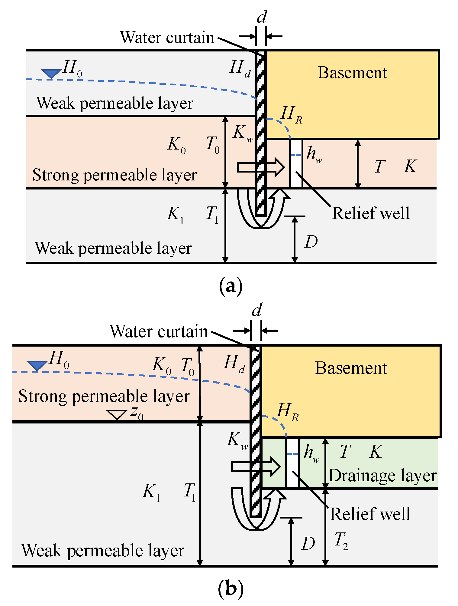
- The primary aquifer layers outside the cut-off wall are categorized into two scenarios: the pressure-bearing mode and the submerged mode. In cases where there are multiple layers of highly permeable strata with negligible variations in permeability coefficients, equivalent permeability coefficients can be employed.
- The material of each soil layer and cut-off wall is homogeneous and isotropic [32].
- The inner edge line of the cut-off wall is an equal head line.
2.2. Seepage Field Inside a Circular Pit
2.3. Ellipse to Circle Mapping
2.4. Inside-Outside Seepage Field Solved in Series
2.5. Processes to Simplify Calculations
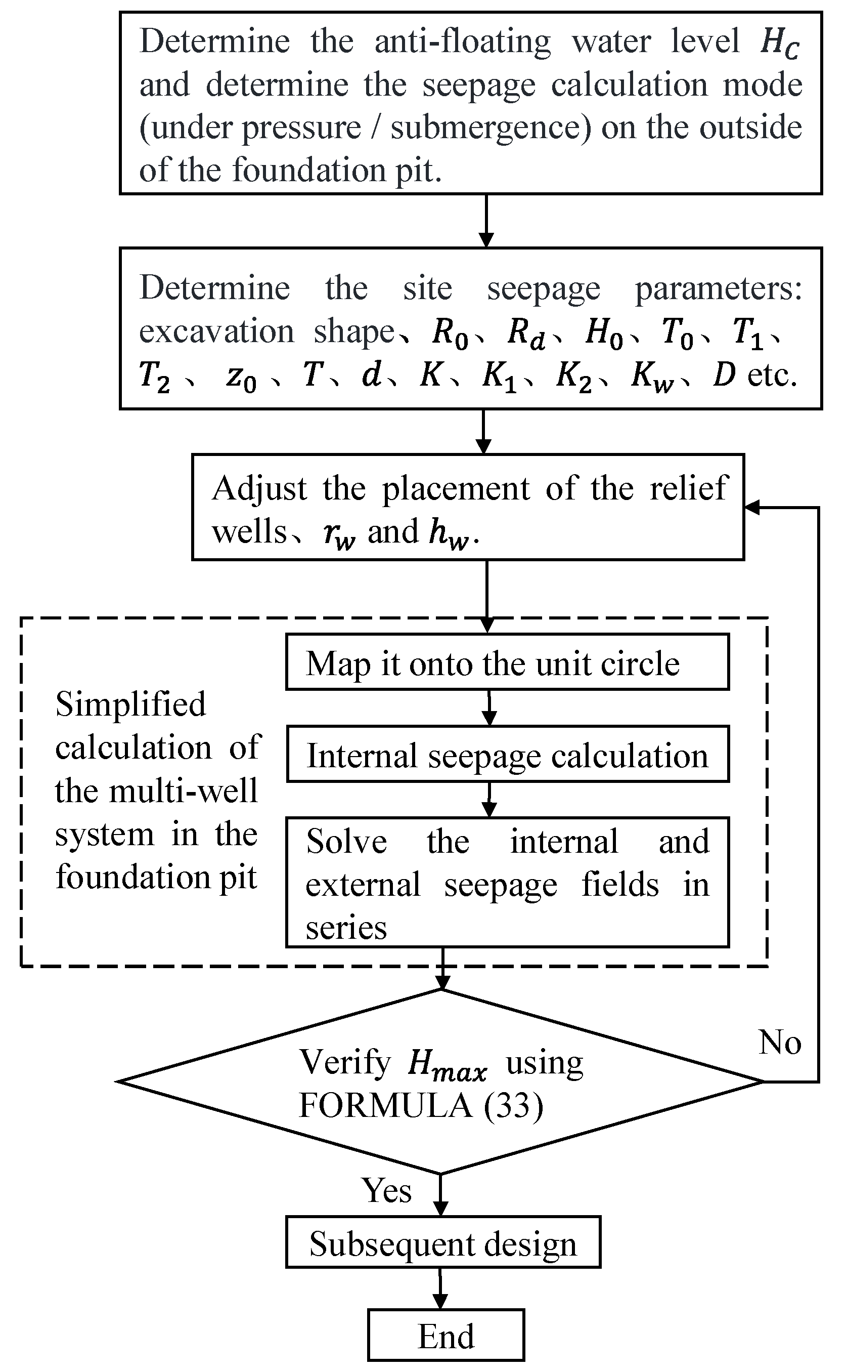
- Determine the parameters: first, determine whether the seepage calculation mode of the outside of the cut-off wall is pressure-bearing or submerged; second, determine the seepage parameters of the site, such as the area of influence of the seepage field , the height of the edge of the area of influence , the thickness of the gravelly sand layer , the thickness of the powdery clay layer , the depth of the relief wells and the thickness of the water-reducing layer , the thickness of the cut-off wall in the pit , the permeability coefficients of the highly permeable layer and the water-reducing layer , the permeability coefficient of the weakly permeable layer , the permeability coefficient of the highly permeable layer , the permeability coefficient of the cut-off wall , the thickness of the weakly permeable layer at the bottom of the cut-off wall , and the shape of the pit, etc. Finally, the location of the relief wells, the diameter of the wells , and the height of the wellhead are adjusted.
- Simplify an arbitrarily shaped pit to an ellipse according to its area and map it to a unit circle. First, according to the shape of the target pit, which is equivalent to the ellipse that it most closely resembles, the target pit is transformed to a unit circle by conformal mapping.
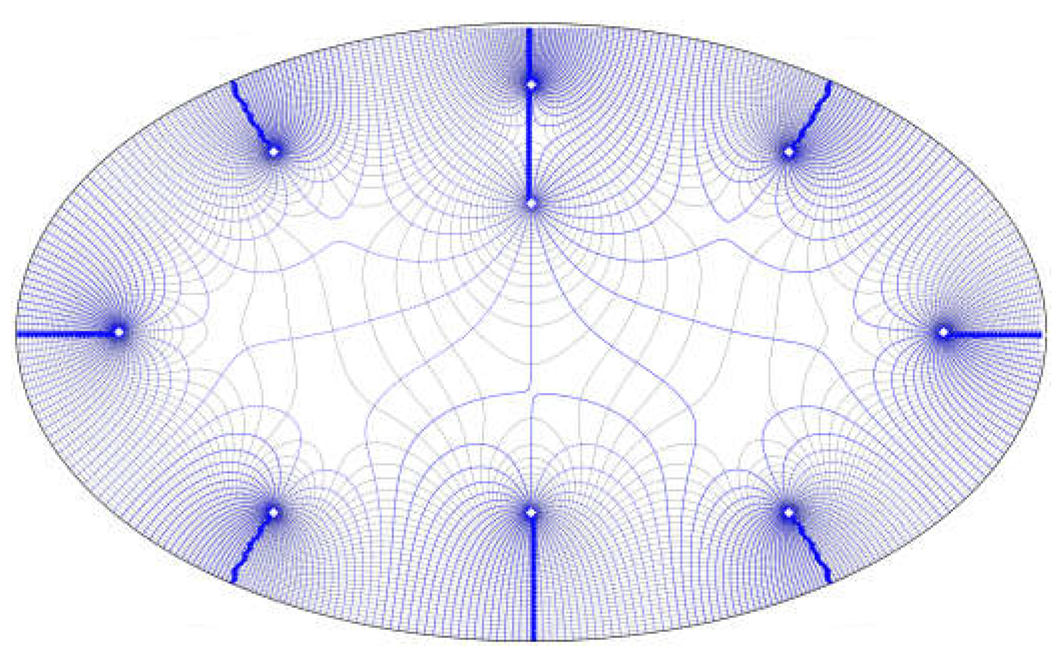
- Internal seepage field calculation. After obtaining the equivalent coordinates of the pit through conformal transformation, assuming the water head height on the inner side of the cut-off wall and the wellhead elevation, let .Together with the transformed equivalent coordinates, substitute them into Equation (6) for calculating the potential function of the internal seepage field in the circular pit with a curtain. This will yield a system of equations , where A is an matrix representing wellbore information, and B is a matrix representing the difference in water head. Solve this system of equations to obtain the matrix x, which represents the discharge flow rate of each well under the assumed water head conditions, i.e., the ratio of discharge flow rates between wells. Finally, the distribution of the seepage field inside the target pit’s curtain under the assumed water head can be obtained by the superposition principle.
- Serial solution of seepage fields on the inner and outer sides. The elliptical pit is transformed into an equivalent circular pit based on the equal area, obtaining the equivalent radius of the pit. By using the resistance coefficient method, the assumed water head in step 2 is related to the actual water head at the site. The resistance coefficient formulas for internal seepage Equation (19), external seepage Equation (14), and seepage and bypass resistance at the cut-off wall Equation (18) are connected in series using the resistance coefficient method formula Equation (20). Finally, the distribution of actual water head heights at the site, as well as the total flow rate and the actual discharge of each well, are solved.
3. Algorithm Validation
3.1. Arithmetic Parameters for Simplified Calculations
3.2. Flow Verification
3.3. Hydraulic Pressure Distribution Verification
3.4. Error Analysis of a Pit Simplified to an Ellipse
4. IDPR Anti-Floating Design and Case Application
4.1. Control Parameters for Anti-Floating Design
4.2. Verification of Actual Engineering Case
5. Conclusions
- For the elliptical pit, it is transformed into a unit circle by conformal mapping, and after obtaining the equivalent coordinates after the transformation, the seepage field of the pit is solved by combining with the resistance coefficient method, so as to obtain the simplified calculation method for the multi-well system of the elliptical pit.
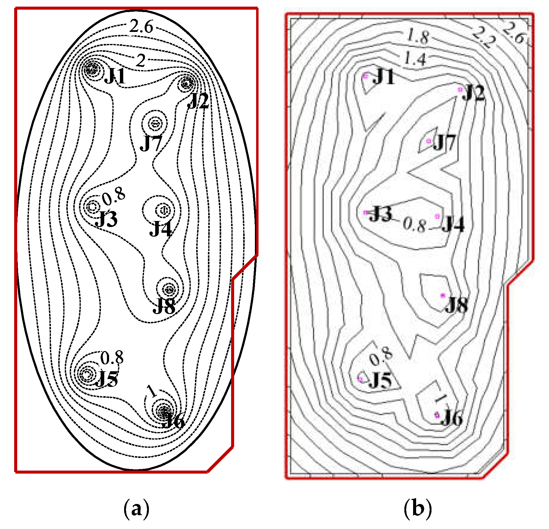
- By comparing the results of the simplified calculation method with the seepage field distribution obtained from finite element calculations, as well as the total flow rate and head, it is observed that the seepage field distribution inside the pit is nearly identical. This demonstrates the high accuracy of the simplified calculation method for the multi-well system of elliptical pits under IDPR conditions. Furthermore, the simplified calculation method was successfully applied to real-world engineering cases. By comparing the results of the simplified calculation with both the finite element calculations and the actual measured data, the reasonableness and practicality of the simplified calculation method were further validated.
- This simplified calculation method is suitable for sites with relatively uniform soil thickness and permeability, such as sites with artificial hydrophobic layers, but its accuracy needs to be further improved for sites with large variations in soil distribution.
Author Contributions
Funding
Informed Consent Statement
Data Availability Statement
Conflicts of Interest
Appendix A
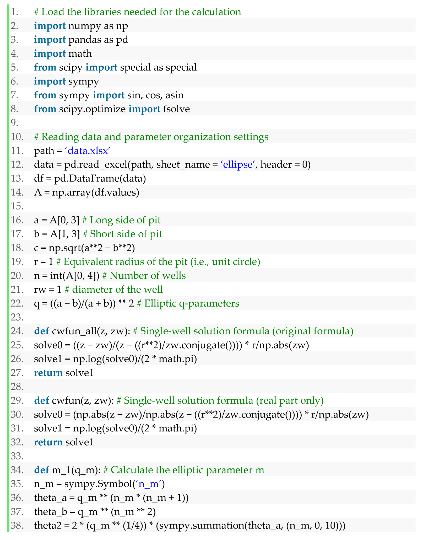
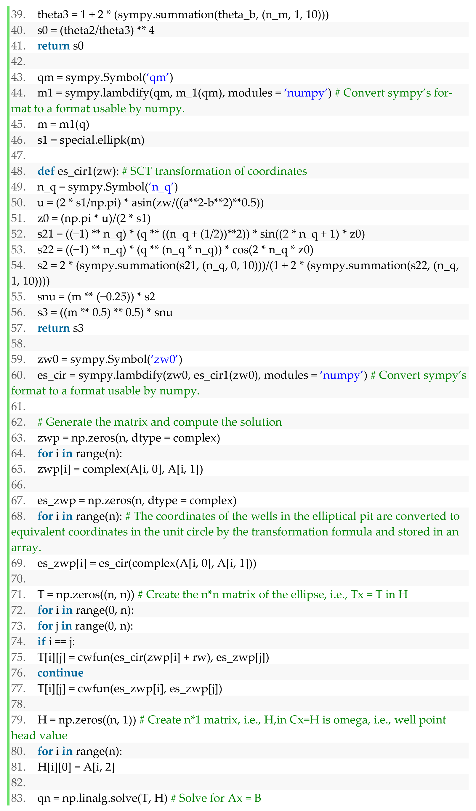
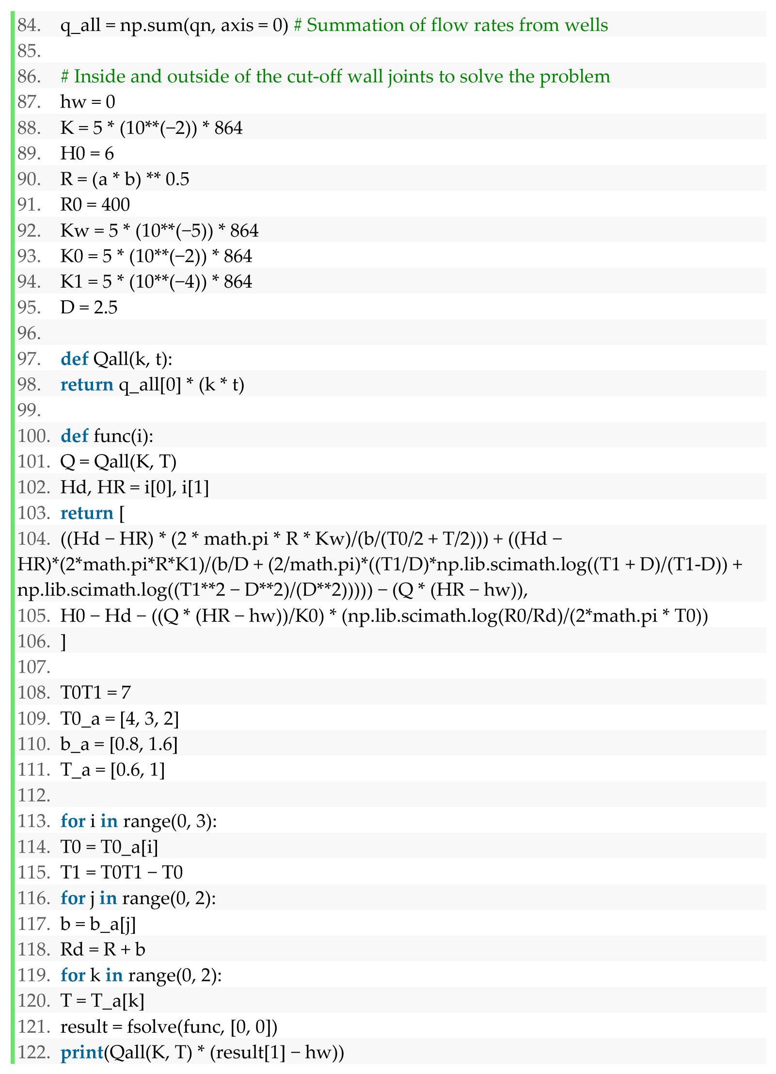
References
- Dezhi, K.; Yanan, G.; Hua, Y. Study on the anti-floating water level of the underground structure’s comprehensive anti-floating. Structures 2023, 56, 104921. [Google Scholar] [CrossRef]
- Wu, Y.; Yang, T.; Li, P.; Lin, J. Investigation of groundwater withdrawal and recharge affecting underground structures in the Shanghai urban area. Sustainability 2019, 11, 7162. [Google Scholar] [CrossRef]
- Sun, W.; Liu, H.; Zhang, W.; Liu, S.; Gao, X. Investigation on overburden thickness considering face and anti-floating stability of shallow shield tunnel. Comput. Geotech. 2023, 160, 105562. [Google Scholar] [CrossRef]
- Yang, L.H.; Wang, H.; Han, Z.G. Analysis and reinforcement on the up-floating accident of the basement of a large commercial complex. Appl. Mech. Mater. 2014, 578, 240–243. [Google Scholar] [CrossRef]
- Zheng, Y.; Xiong, J.; Liu, T.; Yue, X.; Qiu, J. Performance of a deep excavation in Lanzhou strong permeable sandy gravel strata. Arab. J. Geosci. 2020, 13, 156. [Google Scholar] [CrossRef]
- Wong, I.H. Methods of resisting hydrostatic uplift in substructures. Tunn. Undergr. Space Technol. 2001, 16, 77–86. [Google Scholar] [CrossRef]
- Zhou, T.; Gao, X.; Guo, Y.; Sun, Y. Design method and experimental study of uplift bearing capacity of the lower enlarged composite pile. Rock Soil Mech. 2019, 40, 3778–3782+3788. [Google Scholar] [CrossRef]
- Zhang, M.; Fan, K.; Liao, S.; Xu, P.; Li, J.; Chen, C. Prediction of ultimate antifloating force of bored piles in urban road crossing overpass. Geofluids 2022, 2022, 8170585. [Google Scholar] [CrossRef]
- Jia, J.; Song, E. The design and test on anti-floating anchorage of large substructure in coastal region. Chin. J. Geotech. Eng. 2002, 24, 769–771. [Google Scholar] [CrossRef]
- Xu, Z.; Lai, Y.; Mei, G. Numerical simulation of water-discharging pressure-relief technology on anti-floating of swimming pools. Chin. J. Geotech. Eng. 2013, 35, 451–455. [Google Scholar]
- Yang, B.; Li, Y.; Gan, Q.; Liu, W.; Kong, Q.; Huang, J. Orthogonal analysis of factors affecting the anti-floating effect of draining decompression. J. Chang. River Sci. Res. Inst. 2016, 33, 121. [Google Scholar] [CrossRef]
- Zhu, D.; Cao, H.; Luo, G.; Pan, H.; Mei, J. Application of interception and drainage anti-floating system in treatment of uplift accidents. Chin. J. Geotech. Eng. 2018, 40, 1746–1752. [Google Scholar] [CrossRef]
- Ling, C.; Dong, J.; Xie, J.; An, X.; Luo, H.; Dong, J. Experimental study on anti-floating model by drainage in underground metro station of the tertiary terrace of Yangtze River in Wuhan. Eng. J. Wuhan Univ. 2023, 56, 1088–1095. [Google Scholar] [CrossRef]
- Cao, Y.; Yuan, X.; Zhang, M.; Lu, C.; Su, P.; Zhao, Y. Design and analysis of drainage depressurization and floatation reduction in the basement of a building on a slope. Build. Struct. 2022, 52, 105–110. [Google Scholar] [CrossRef]
- Luo, Y.; Chen, J.; Wang, Y.; Shen, P. Anti-floating failure mechanism of underground structures in expansive soil area and application of active anti-floating measures. Hydrogeol. Eng. Geol. 2022, 49, 64–73. [Google Scholar] [CrossRef]
- Zhu, D.; Luo, C.; Li, J. Understanding and thinking about “Technical Standard for Building Engineering against Uplift”. Chin. J. Undergr. Space Eng. 2022, 18, 628–634. [Google Scholar]
- Li, J.; Zhu, G.; Wang, J.; Zeng, P. Application of active anti-floating in underground structure based on automatic drainage system. In Proceedings of the International Conference on Civil, Architecture and Engineering Management, Taiyuan, China, 16–18 October 2020. [Google Scholar] [CrossRef]
- Zhu, D.; Cao, H.; Luo, G.; Pan, H.; Luo, C. Simplified calculation and design method of multi-well system for anti-uplifting based on intercepting and discharging water. Chin. J. Geotech. Eng. 2021, 43, 1986–1993. [Google Scholar] [CrossRef]
- Li, Y.; Chen, D.; Liu, X.; Xie, X.; Tong, X.; Zhang, J. Simplified calculation method of decompression dewatering for deep excavation with suspended waterproof curtain. Rock Soil Mech. 2021, 42, 826–832. [Google Scholar] [CrossRef]
- Yuan, H.; Zhang, Q. Optimization design and application of dewatering-recharge system in deep excavation. J. Shanghai Jiao Tong Univ. 2013, 47, 1424–1429. [Google Scholar] [CrossRef]
- Gao, Y.; Dai, F.; Lei, B.; Zeng, C.; Sun, H. Calculation of saturation curve under the action of dewatering and recharge in foundation pit. Acta Geol. Sin. 2019, 93, 127–132. [Google Scholar] [CrossRef]
- Mao, C. Seepage Computation Analysis & Control, 2nd ed.; China Water&Power Press: Beijing, China, 2003. [Google Scholar]
- Wu, L. Design and Execution of Dewatering & Theory of Seepage in Deep Excavation; China Communication Press: Beijing, China, 2003. [Google Scholar]
- Wang, R. The effect of omitting the thickness of fluidised bed sheet piling on the calculation of filtration (seepage) flow. J. Zhejiang Univ. 1957, 3, 9–27. [Google Scholar]
- Hu, Y. Study on Calculation Method of Well Considering Impervious Structure of Foundation Pit. Master’s Thesis, South China University of Technology, Guangzhou, China, 2018. [Google Scholar]
- P.P.Чyгaeв. Percolation Theory; Higher Education Press: Beijing, China, 1959. [Google Scholar]
- Luo, G.; Qiu, J.; Cao, H.; Pan, H. Simplified method for calculating inflow into a deep excavation with consideration of the effects of cutoff walls. Hydrogeol. J. 2018, 26, 2853–2865. [Google Scholar] [CrossRef]
- Mei, J.; Cao, H.; Luo, G.; Pan, H. Analytical method for groundwater seepage through and beneath a fully penetrating cut-off wall considering effects of wall permeability and thickness. Water 2022, 14, 3982. [Google Scholar] [CrossRef]
- Wang, Y.; Ji, A.; Cui, J. Numerical solution of Schwarz-Christoffel transformation from rectangles to arbitrary polygonal domains. Appl. Math. Mech. 2019, 40, 75–88. [Google Scholar] [CrossRef]
- Squire, W. Computer implementation of the Schwarz-Christoffel transformation. J. Frankl. Inst. 1975, 299, 315–322. [Google Scholar] [CrossRef]
- Delillo, T.K. On some relations among numerical conformal mapping methods. J. Comput. Appl. Math. 1987, 19, 363–377. [Google Scholar] [CrossRef][Green Version]
- Yu, J.; Zhang, Y.; Zheng, J.; Zhang, Z. Analytical solution of two-dimensional steady-state seepage field in a pit considering a diving surface. Rock Soil Mech. 2023, 44, 1–8. [Google Scholar] [CrossRef]
- Fornberg, B. A numerical method for conformal mappings. SIAM J. Sci. Stat. Comput. 1980, 1, 386–400. [Google Scholar] [CrossRef][Green Version]
- Driscoll, T.; Trefethen, L. Schwarz-Christoffel Mapping; Cambridge University Press: Cambridge, UK, 2002. [Google Scholar]
- Fenton, J.; Gardiner-Garden, R.S. Rapidly-convergent methods for evaluating elliptic integrals and theta and elliptic functions. ANZIAM J. 1982, 24, 47–58. [Google Scholar] [CrossRef]
- Manual, E. Design, Construction, and Maintenance of Relief Wells; US Army Corps of Engineers: Washington, DC, USA, 1994. [Google Scholar]





| R0 (m) | n | hw (m) | H0 (m) | D (m) | K (cm/s) | K0 (cm/s) | K1 (cm/s) | Kw (cm/s) |
|---|---|---|---|---|---|---|---|---|
| 400.00 | 20 | 0.00 | 6.00 | 2.50 |
| a (m) | b (m) | T0 (m) | T1 (m) | Distribution | rw (m) | T (m) | d (m) |
|---|---|---|---|---|---|---|---|
| 90 | 70 | 2.00 | 5.00 | A | 0.50 | 0.60 | 0.80 |
| 100 | 60 | 3.00 | 4.00 | B | 1.00 | 1.00 | 1.60 |
| 120 | 50 | 4.00 | 3.00 | C | - | - | - |
| a (m) | b (m) | T0 (m) | T1 (m) | z0 (m) | Distribution | rw (m) | T (m) | T2 (m) | d (m) |
|---|---|---|---|---|---|---|---|---|---|
| 90 | 70 | 2.50 | 7.50 | 7.50 | A | 0.50 | 0.50 | 3.50 | 0.80 |
| 100 | 60 | 3.00 | 7.00 | 7.00 | B | 1.00 | 0.80 | 3.20 | 1.60 |
| 120 | 50 | 3.50 | 6.50 | 6.50 | C | - | - | - | - |
Disclaimer/Publisher’s Note: The statements, opinions and data contained in all publications are solely those of the individual author(s) and contributor(s) and not of MDPI and/or the editor(s). MDPI and/or the editor(s) disclaim responsibility for any injury to people or property resulting from any ideas, methods, instructions or products referred to in the content. |
© 2023 by the authors. Licensee MDPI, Basel, Switzerland. This article is an open access article distributed under the terms and conditions of the Creative Commons Attribution (CC BY) license (https://creativecommons.org/licenses/by/4.0/).
Share and Cite
Luo, G.; Yang, F.; Li, H.; Pan, H.; Cao, H. Simplified Calculation Method for Active Anti-Floating of Elliptical Basements by Relief Wells. Appl. Sci. 2023, 13, 12647. https://doi.org/10.3390/app132312647
Luo G, Yang F, Li H, Pan H, Cao H. Simplified Calculation Method for Active Anti-Floating of Elliptical Basements by Relief Wells. Applied Sciences. 2023; 13(23):12647. https://doi.org/10.3390/app132312647
Chicago/Turabian StyleLuo, Guanyong, Fei Yang, Haoxi Li, Hong Pan, and Hong Cao. 2023. "Simplified Calculation Method for Active Anti-Floating of Elliptical Basements by Relief Wells" Applied Sciences 13, no. 23: 12647. https://doi.org/10.3390/app132312647
APA StyleLuo, G., Yang, F., Li, H., Pan, H., & Cao, H. (2023). Simplified Calculation Method for Active Anti-Floating of Elliptical Basements by Relief Wells. Applied Sciences, 13(23), 12647. https://doi.org/10.3390/app132312647


