Article

Influence of Fastener Stiffness and Damping on Vibration Transfer Characteristics of Urban Railway Bridge Lines Using Vibration Power Flow Method

1
School of Mechanical Engineering, Lanzhou Jiaotong University, Lanzhou 730070, China
2
CRRC Zhuzhou Institute Co., Ltd., Zhuzhou 412007, China
*
Author to whom correspondence should be addressed.
Appl. Sci. 2023, 13(23), 12543; https://doi.org/10.3390/app132312543
Submission received: 7 October 2023 / Revised: 7 November 2023 / Accepted: 16 November 2023 / Published: 21 November 2023
(This article belongs to the Special Issue Railway Structure and Track Engineering)

Abstract

:
The problem of vibration in urban rail transportation has become a current research hotspot. When a train passes through a bridge line at high speed, it interacts with the rail, leading to vibration energy transfer and causing issues such as vibration and noise in the line infrastructure. To propose a more targeted vibration-damping track structure, it is necessary to explore the vibration characteristics of urban rail transit bridge lines and understand the regulations governing the distribution of vibration energy. This paper employs the theory of vehicle–rail–bridge interaction to establish a coupled dynamics model for a subway A-type vehicle–integral ballast bed–box girder bridge. Based on the proposed model, the transmission characteristics and distribution of vibration energy in the rail–bridge system are systematically analyzed and the influence of the parameters of the track structural components on the power flow of the system are investigated. The results of this study indicate that low-frequency vibration energy in the track system of urban rail transit bridges is primarily concentrated within the track structure, whereas high-frequency vibration energy is mainly focused on the rail. The fastener, as a component connecting the rail and the overall roadbed, has different effects on the peak value of the power flow and the accumulation of vibration energy in various components such as the rail, the overall roadbed, the top plate of the box girder bridge, and the bottom plate in different frequency bands due to its own stiffness and damping. An appropriate increase in fastener damping is beneficial for reducing the accumulation of low-frequency vibration energy in the track structure.

1. Introduction

The rapid development of urban rail transport has greatly facilitated travel for residents in large cities. However, the vibration and noise issues arising from trains passing through densely populated areas along rail transit lines have increasingly drawn public attention. Prolonged and frequent vibrations can lead to structural damage in tracks, harm buildings situated near the rail lines, and interfere with the operation of high-precision instruments, thus impacting people’s daily lives and productivity. In order to reduce the vibration problem of urban rail transit, vibration-damping tracks have been implemented on numerous rail lines [1,2]. The effects of mobile vehicle impact and damping on the vibration of rail–bridge systems were verified by experiments on test-bed method by Jian Yu [3]. Caiyou Zhao analyzed the impact of vibration isolator effectiveness on the vibration-damping effect of floating plate rail by establishing a vehicle–rail steel-spring floating-plate rail interaction model [4]. Xin Zhou studied the effects of three track structure forms, namely, ordinary monolithic track bed, slab track bed, and floating-slab track, on the vibration of rail transportation [5]. Paul analyzed the effect of track irregularities on the dynamic response of bridges, taking into account the stiffness and damping of the soil base [6]. These studies have analyzed the vibration response transmitted to the bridge structure from various phenomena, such as vehicles, vibration isolators, and track structure forms. However, the studies have not systematically revealed the vibration transmission problem among the structures of the bridge line.
As people’s demand for higher operating speeds in urban rail transport increases, the intensity of vibration sources in urban rail transport also intensifies. The development of more targeted measures to dampen vibrations on the tracks has become an urgent requirement to address this issue. The key to solving this problem is identifying track structure components with significant vibration energy accumulation and understanding how changing structural parameters affects this energy accumulation.
The power flow method, based on the theory of vibration isolation, has proven highly effective in analyzing energy transfer and accumulation within structures. This method offers a comprehensive reflection of vibration energy traits within the structure. Notably, its advantage lies in frequency domain analysis, allowing precise representation of vibration energy distribution across each layer of the structure. Following Goyder’s description and discourse on a continuum-dynamics-centered power flow analysis approach [7,8,9], the power flow theory finds extensive application in diverse fields like marine, aerospace, and machinery [10,11,12]. This approach is equally relevant in the context of rail transportation, constituting a continuous dynamics challenge. Sudheesh Kumar examined the impact of velocity on vibration power flow within simply supported beams subjected to multipoint dynamic loading, estimating bridge vibration power distribution [13]. Na Fu explored the vibration energy characteristics of a double-block ballasted track through a power flow method rooted in a train–track–bridge interaction model [14]. Dhananjay proposed a subway tunnel vibration power flow calculation method, comparing power flow between ordinary monolithic track beds and floating-slab tracks [15].
The application of the vibration power flow method to address the dynamics issues of urban railway bridge lines allows for solving structural vibration problems involving multiple damping layers and components. This approach offers the opportunity to analyze the energy transfer dynamics of each section of the track structure on the bridge. Building on this foundation, more targeted rail transit vibration-damping products can be developed according to the vibration accumulation of each component, providing certain theoretical support for the subsequent design of vibration-damping track.
Therefore, based on the vehicle–track–bridge interaction theory [16], this paper considers the vehicle subsystem, the track structure subsystem, and the bridge subsystem as a dynamic system problem with an interactive relationship. We establish a track–bridge power flow calculation model to analyze the transfer characteristics and distribution of vibration energy in the track–bridge system. And we study the influence of the parameters of the track structure components on the power flow of the system.

2. Theoretical Analysis Model and Calculation Method

The train is assumed to be a complex system with multiple rigid body components that are connected to each other by springs and dampers. Both the track and the bridge are considered as elastomers with continuously distributed masses. Based on the theory of vehicle–track–bridge interaction [17], this paper begins by establishing a coupled dynamics model of a subway A-type vehicle–integral ballast bed–box girder bridge [18,19,20]. The model employs the six-level power spectrum of the U.S. railroads as the input condition for resolving the subsequent power flow analysis of external excitation. Subsequently, a power flow analysis model of the railroad track bridges is established to investigate the vibration energy transfer characteristics of the entire system.

2.1. Establishment of Vehicle Model and Determination of Parameters

Based on the multi-rigid body system dynamics theory, the subway A-type vehicle is mainly considered as a multi-rigid body system with the vehicle body, two bogies and four wheel pairs, and the main motion states of the vehicle structure in the study include the vehicle body, the front and rear bogies’ sinking and nodding motions, and the pendant vibration and nodding of the four wheel pairs, with a total of 14 degrees of freedom. The vehicle–track–bridge coupled dynamics model and its dynamics parameters are as shown in Figure 1 and Table 1 and Table 2.

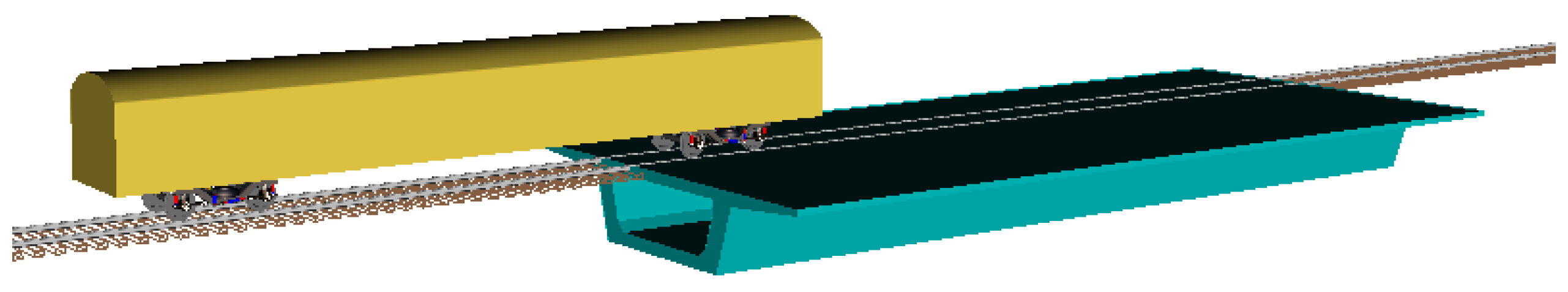
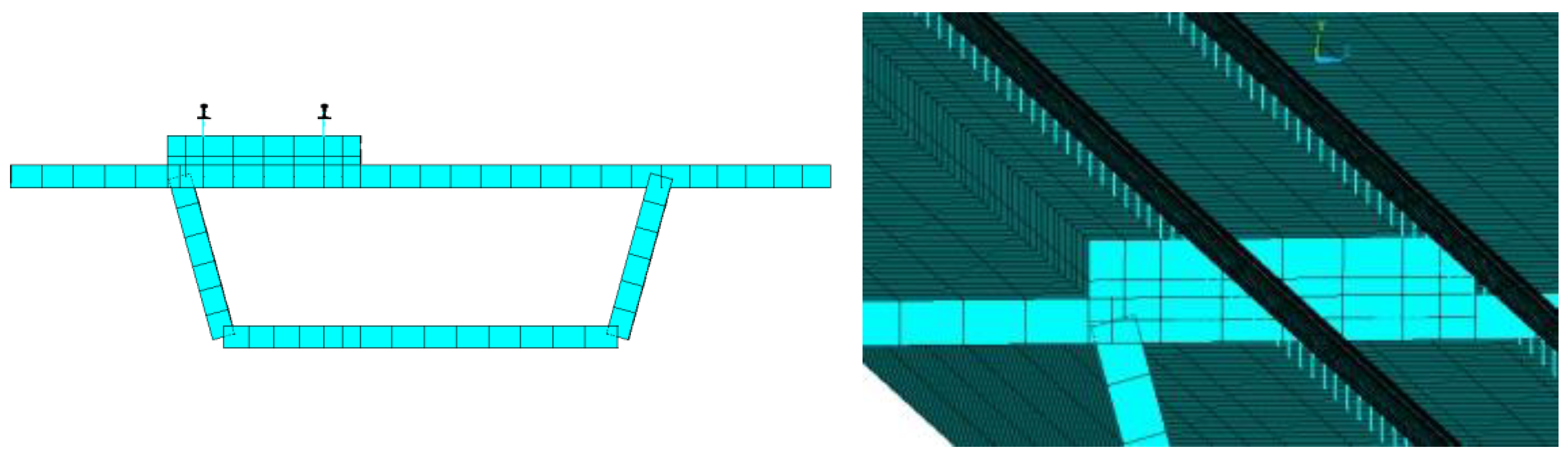
2.2. Finite-Element Model of Track–Box Girder Bridge

In the dynamics model of the vehicle–track–bridge system, this study primarily employs Ansys to create the finite-element model encompassing the track-fastening–integral ballast bed–box girder bridge. Specifically, the track is simulated using Beam188 elements, the fastener system is represented by Combin14 elements, and the entire track bed is defined using Solid45 elements. Box girder bridges are mainly composed of top, web, and bottom plates, which are made of the same material and have basically the same thickness. To enhance computational efficiency, the model incorporates Shell63 elements, which take into account the actual thickness of the box girder bridge. The finite-element model of the line infrastructure, along with its dynamic parameters, is depicted in Figure 2 and detailed in Table 3.
In the numerical simulation, the operating speed of the subway A-type car is established at 83 km/h, and the sixth-grade power spectral density of the American railway is adopted as the external excitation, depicted in Figure 3. The dynamic response of the comprehensive vehicle–track–bridge system is computed, and the resultant node velocities and node forces are employed as input parameters for subsequent power flow analysis.

2.3. Method for Calculating Vibration Power Flow

Since this paper mainly studies the vibration energy transfer of the vibration-damping track on the bridge line, the frequency domain average power is selected to evaluate its transmission characteristics. The average power calculation formula is as follows.
P ( w ) = 1 2 Re ( F V )
where  P ( w )  is the power flow, and its unit is N·m/s, that is,  W . The complex values of  F  and  V  represent the velocity in the frequency domain. Re represents the real part of a complex number. The superscript * represents conjugation.
The velocity and force of the track, integral ballast bed, and box girder bridge joints obtained from the vehicle–track–bridge coupling dynamics model are used as input conditions for power flow analysis. However, in the dynamic analysis modeling presented in this paper, beam elements and plate shell elements are used for the track and box girder bridge, respectively. This approach makes it impossible to directly extract the nodal forces of each node. Therefore, the internal stress of the node is extracted from the element in which the node is situated, rather than directly from the node force.
In the power flow analysis, if the entire span of the overhead line is used for solving, a significant number of nodes are involved in the calculation process, leading to a notable reduction in solving efficiency. Given that this paper primarily analyzes the power flow transmission characteristics of elevated lines, a finite-element model of 1/6 of the lines can be selected for analysis. In other words, the 5 m track and bridge structure can be calculated to effectively improve the calculation efficiency while ensuring the accuracy of the calculation structure. The total power flow can be expressed as follows.
P w ( k ) = 1 2 i = 1 n Re [ F i ( k ) V k i ( k ) ]
where  i  is the node number of the desired power flow.  n  is the total number of nodes.  k  is the calculation frequency point, the unit is Hz.
The power flow characteristics of the track, integral ballast bed, and box girder bridge can be obtained individually. The power flow characteristics of the entire system can then be determined by summing the characteristics of each subsystem.
To facilitate a more intuitive comparative analysis, the evaluation employs the relative power flow of the structure, which is expressed as follows.
P ( k ) = 20 log [ P w ( k ) P 0 ]
where  P w ( k )  is the total power flow of the structure corresponding to frequency  k , and the unit is N·m/s;  P 0  is the reference power flow, and the reference power flow on the bridge under the action of track irregularity is  P 0 = 1 × 10 10 , and the unit is N·m/s.

3. Vibration Transmission Characteristics of Urban Track Transit Bridge Lines

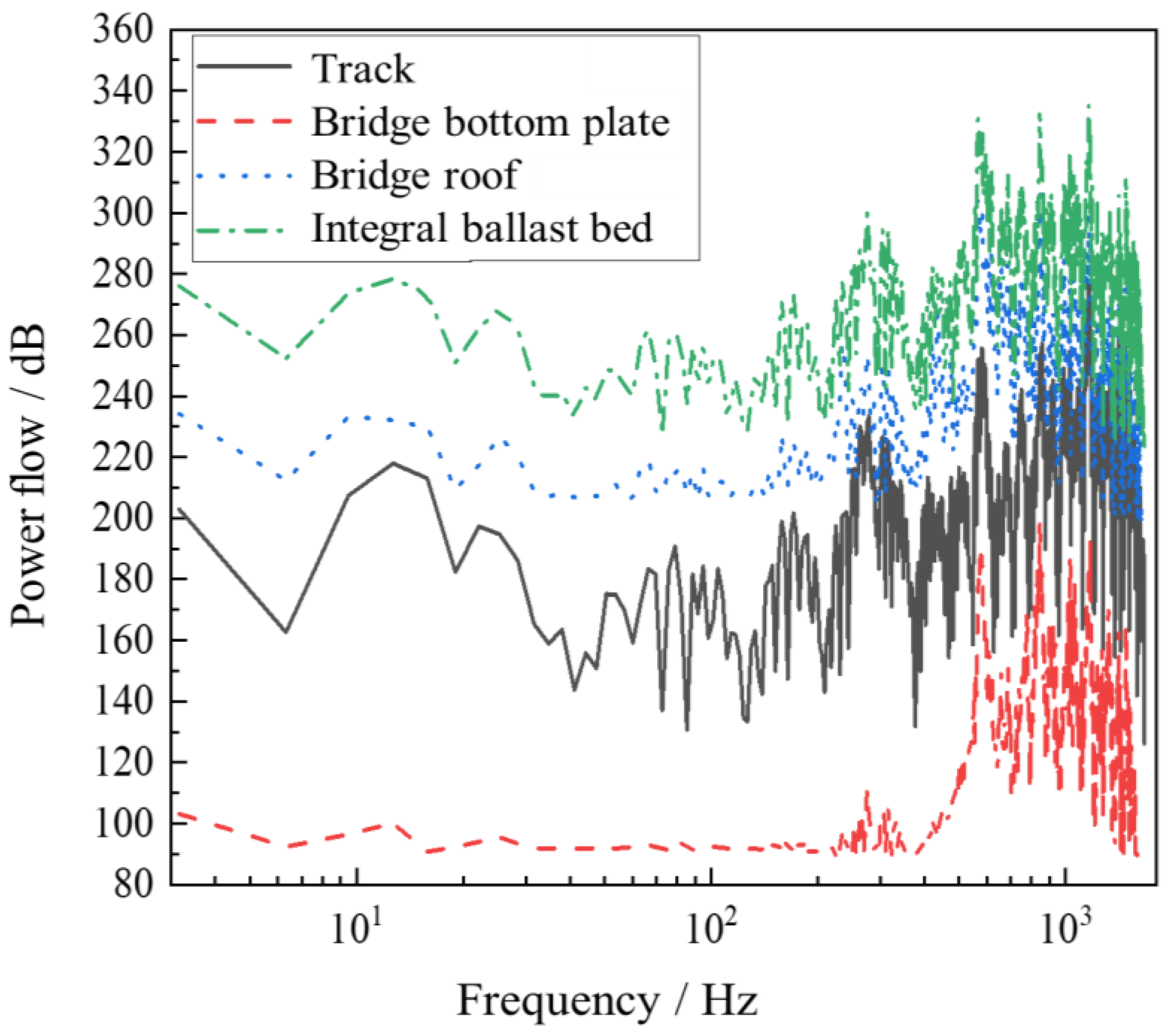
3.1. Vibration Energy Transfer Characteristics of Integral Ballast Bed Damping Track

Figure 4 displays the power flow transmission characteristics of a track bridge line with an integral ballast bed. Based on the power flow spectrum curve, the following conclusions can be drawn.
Firstly, the initial peak of the ballast bed and the roof of the box girder bridge are evident at approximately 250 Hz. The natural frequency of the first mode of vertical track bending is 200 Hz. Consequently, a coupling effect exists between the track, integral ballast bed, and the top plate of the box girder bridge at 200 Hz.
Secondly, the second peak in power flow is observed in the track, integral ballast bed, box girder bridge roof, and bottom plate at around 600 Hz. Among these, the integral ballast bed exhibits the highest cumulative power flow, reaching approximately 300 dB, while the lowest cumulative power flow is found in the bottom plate, at approximately 175 dB.
Thirdly, within the frequency domain below 2000 Hz, notable power flow peaks are additionally present near 800 Hz, 1200 Hz, and 1400 Hz.
Fourthly, within the entire line system, the power flow distribution diminishes in the sequence of the integral ballast bed, bridge roof, track, and bridge bottom plate. Among these, the power flow characteristics of the integral ballast bed exhibit the most significance, indicating a substantial accumulation of vibration energy within the ballast bed.
During the transfer of vibration energy within the track structure, certain structural elements may either consume or store a portion of the energy. As a result, potential issues can arise, such as the attenuation of vibration energy or the amplification of vibrations in specific components due to energy storage. The fastener, functioning as a component that links the track and the integral ballast bed, exerts a noticeable impact on the power flow of both the track and the ballast. The disparity in power flow between the track and the ballast can serve as an indicator of the influence of the fastener on power flow transmission. In the lower frequency range, the amplitude of attenuation of vibration energy in the fastener and ballast increases as the frequency rises. The highest attenuation occurs near 100 Hz and 300 Hz. In the middle- and high-frequency bands, the amplitude of attenuation of vibration energy decreases as the frequency increases. This indicates that vibration energy within the low-frequency range is more readily absorbed or stored within the fastener system. Through a comparison of the power flow transmission characteristics between the bridge roof and the floor, it becomes evident that the power flow behaviors of the bridge roof and the floor significantly diverge within the low-frequency range. This observation suggests that, in the low-frequency band, the vibration energy primarily concentrates in the bridge roof. Moreover, it underscores the fact that, within the low-frequency range, the bridge roof constitutes the principal source of low-frequency sound in the bridge structure. This characteristic aligns with the structural focus of the current study.
Based on the above analysis, it is evident that the power flow characteristics of the entire track bed are more significant than those of the track. In the vibration transmission process, the fastener system serves as a crucial connection component closely related to the track bed and the track. Hence, the relevant parameters of the fastener system are expected to have a significant impact on the power flow transmission characteristics. Consequently, the effects of fastener stiffness and damping parameters on power flow transmission characteristics will be further analyzed and systematically studied in the following paragraphs.

3.2. Effect of Fastener Parameters on System Power Flow Characteristics

The fastener, serving as the connecting component between the entire track bed and the track, holds a crucial role in governing the power flow transmission within the track structure. The stiffness and damping of the fastener have a significant impact on this process. Exactly based on the concept of control variables, two methods are employed in this study to analyze the influence of fastener parameters on the transmission characteristics of power flow within the system. The first method involves changing the stiffness of the fastener while maintaining its damping constant. The second method entails altering the damping of the fastener while keeping its stiffness constant. Through these approaches, the influence of deduction parameters on power flow transmission characteristics is thoroughly investigated.

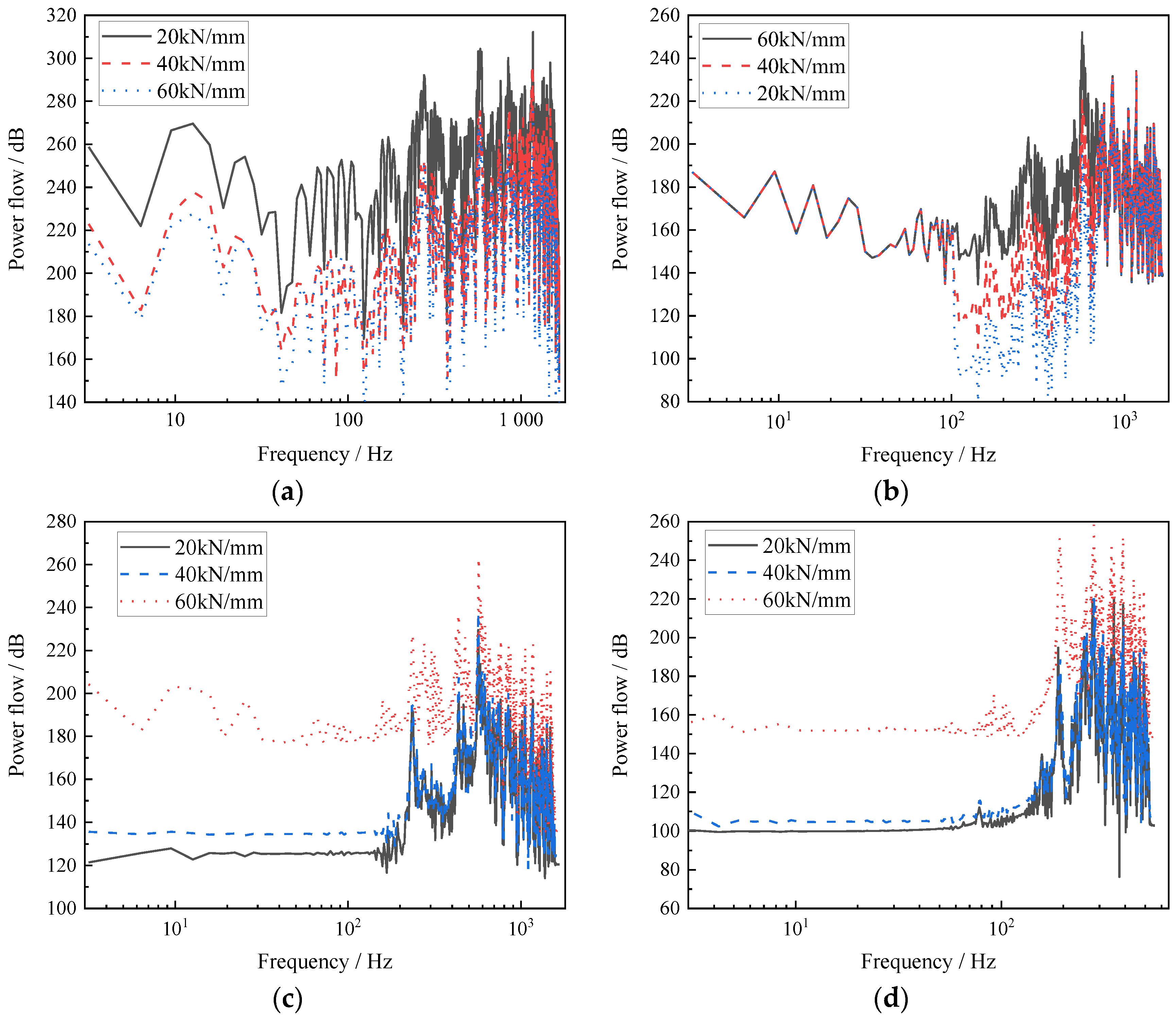
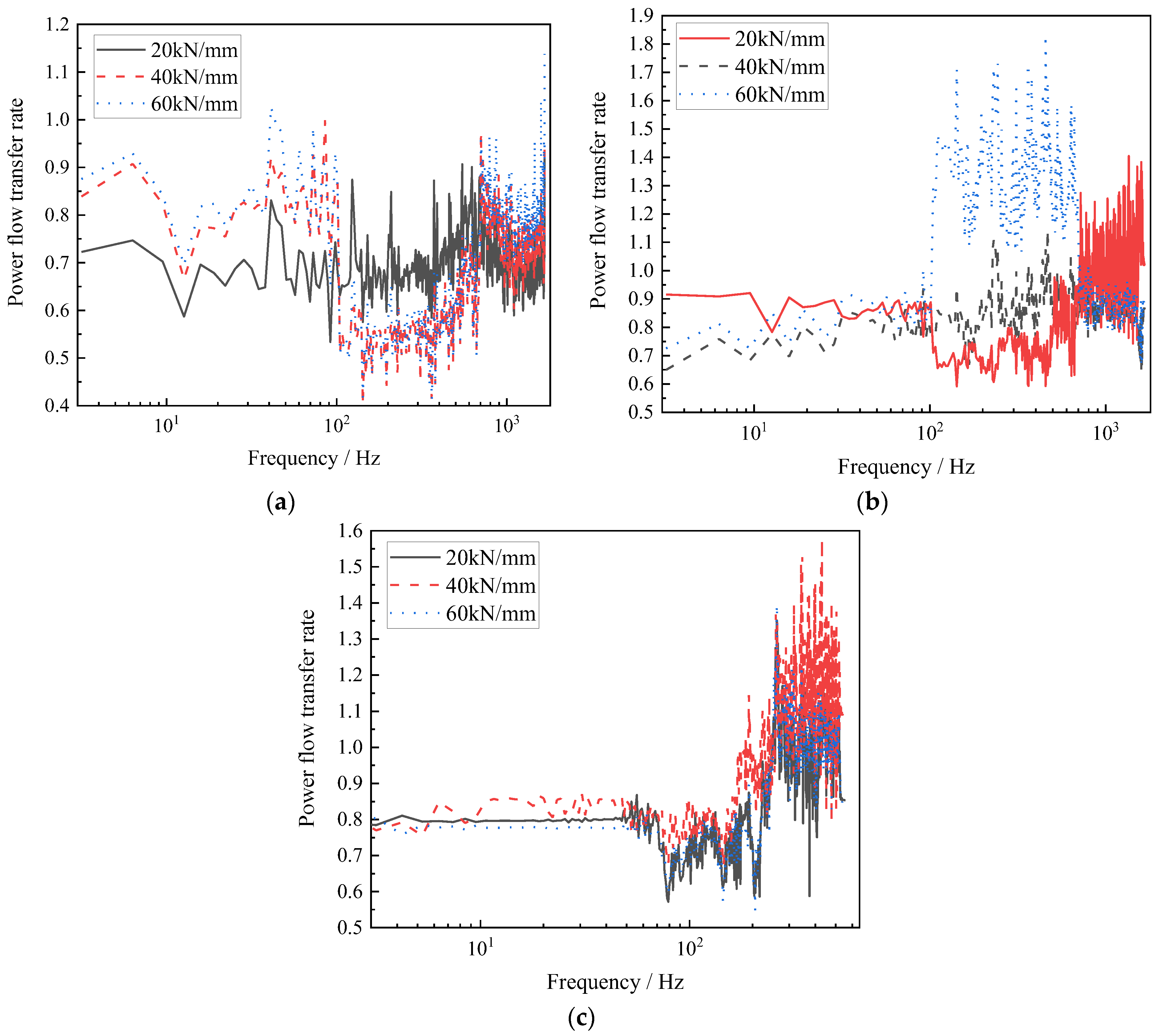
3.2.1. Effect of Fastener Stiffness on Power Flow Transmission Characteristics

Figure 5 illustrates the spectrum curve depicting the variation of power flow for the track, integral ballast bed, bridge roof, and bridge bottom plate in relation to changes in fastener stiffness.
With the fastener damping set at 40 kN/s/m and unchanged, the power flow of each subsystem is individually analyzed for fastener stiffness values of 20 kN/mm, 40 kN/mm, and 60 kN/mm. Indeed, the figure demonstrates that the power flow characteristics of the track are significantly impacted by the stiffness of the fastener within the frequency range of 0–1200 Hz. In essence, there is a high sensitivity between track power flow and fastener stiffness, particularly within the middle- and low-frequency domain. The track power flow reaches its maximum at 1160 Hz, with power flow peaks for the three stiffness values registering at 297 dB, 277 dB, and 256 dB. Regarding the influence of fastener stiffness on ballast power flow, it is primarily concentrated within the frequency range of 100–700 Hz, peaking at 600 Hz. However, it is worth noting that the power flow of the entire ballast remains consistent within the high-frequency band. This indicates that the power flow of the whole ballast at high frequency is not affected by the stiffness of the fastener.
The power flow characteristics of the box girder bridge roof within the 0–400 Hz range display significant variation, with changes in fastener stiffness. Within the 0–200 Hz range, a higher fastener stiffness facilitates more effective transfer of vibration energy to the bridge roof. At 230 Hz, the power flow of the bridge roof reaches its maximum value. In the 200–400 Hz frequency band, the impact of fastener stiffness on the power flow of the bridge roof becomes more pronounced as the fastener stiffness increases. For fastener stiffness values of 20 kN/mm and 40 kN/mm, the power flow of the bridge roof is similar, with an increase of less than 10%. Beyond 400 Hz, fastener stiffness has minimal influence on the power flow of the bridge roof, and the spectrum curve remains relatively consistent.
The influence of fastener stiffness on the power flow of both the bridge bottom plate and bridge roof plate exhibits similar patterns. However, a notable distinction arises in the fact that fastener stiffness has a more pronounced effect on the power flow of the bridge bottom plate within the low-frequency band. The frequency range where fastener stiffness affects power flow is primarily between 0 and 270 Hz. Within this range, the power flow of the bridge bottom plate increases with higher fastener stiffness. When the fastener stiffness increases from 20 kN/mm to 40 kN/mm, the power flow increases by approximately 10%. Similarly, when the fastener stiffness increases from 40 kN/mm to 60 kN/mm, the power flow experiences an approximately 50% increase. These outcomes underscore the significant impact of fastener stiffness on the power flow of the bridge bottom plate in the low-frequency range. Within the frequency range of 270–520 Hz, fastener stiffness exerts minimal influence on the bridge bottom plate’s power flow. For frequencies exceeding 520 Hz, the impact of fastener stiffness on the bridge becomes minor, and power flow characteristics tend to stabilize. With fastener stiffness values of 20 kN/mm, 40 kN/mm, and 60 kN/mm, the power flow of the bridge stabilizes at 102 dB, 105 dB, and 148 dB, respectively.

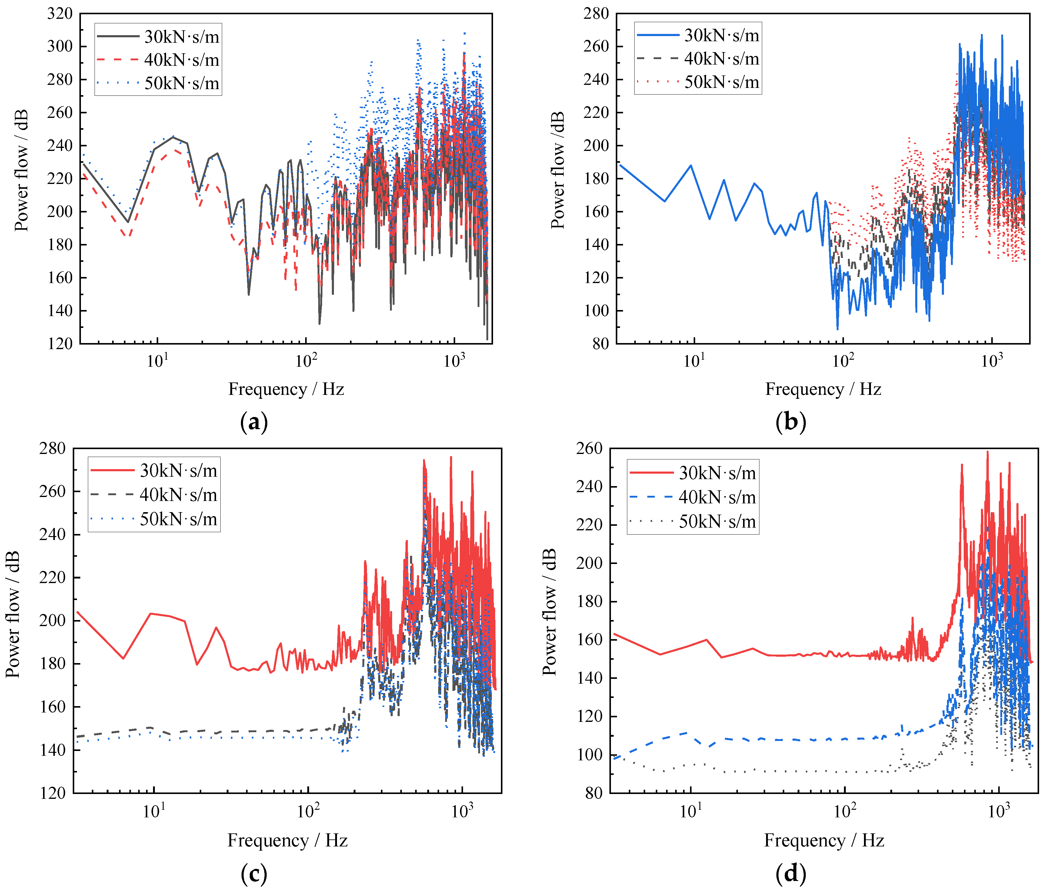
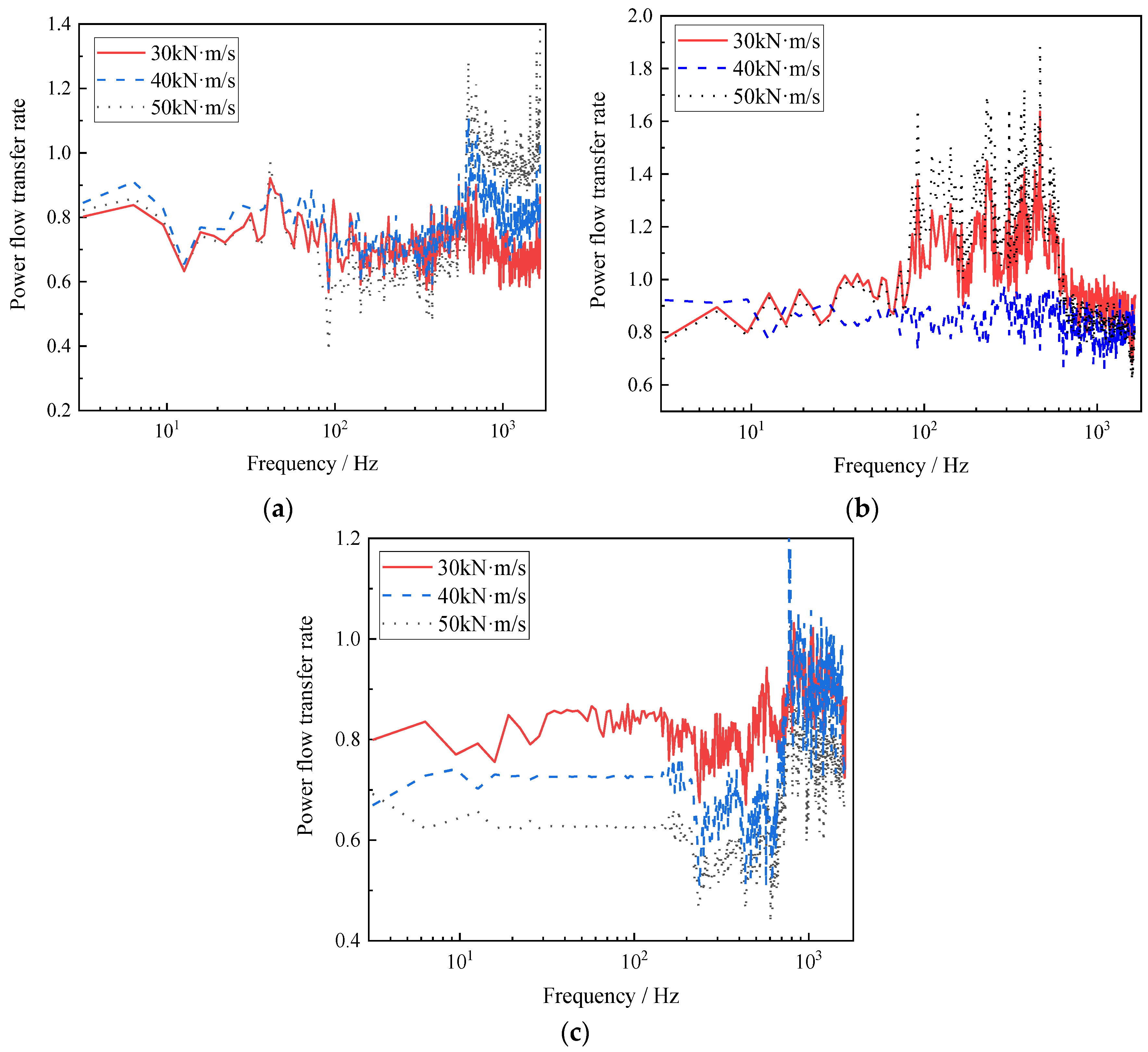
3.2.2. Impact of Fastener Damping on Power Flow Transmission Characteristics

Figure 6 illustrates the spectrum curves depicting the power flow of the track, integral ballast, bridge roof, and bridge bottom at 30 kN·s/m, 40 kN·s/m, and 50 kN·s/m for fastener damping conditions. This analysis aims to further examine the impact of fastener damping on the energy transfer dynamics of the overall system.
As observed in Figure 6, within the low-frequency range of 0–100 Hz, fastener damping exerts minimal influence on track power flow, and the spectrum curves for the three operating conditions align closely. As frequency rises, the peak values of track power flow emerge at 300 Hz, 600 Hz, 800 Hz, 1200 Hz, and 1600 Hz. Fastener damping significantly impacts the peak values at 600 Hz and 800 Hz, thereby chiefly influencing the power flow transmission characteristics within the high-frequency band for the track.
The influence of fastener damping on ballast power flow is primarily evident in the 80–600 Hz range, exhibiting a diminishing trend with increasing fastener damping. The power flow transfer characteristics of the ballast are inversely proportional to fastener damping. Nevertheless, beyond 600 Hz, the relationship becomes proportional.
Fastener damping notably affects the power flow of the bridge roof, particularly the vibration energy transferred to the bridge roof within the 0–200 Hz range, which decreases with rising fastener damping. The impact magnitude diminishes with increasing frequency.

4. Vertical Vibration Transmission Characteristics of Urban Track Transit Integral Ballast Bed–Box Girder Bridge

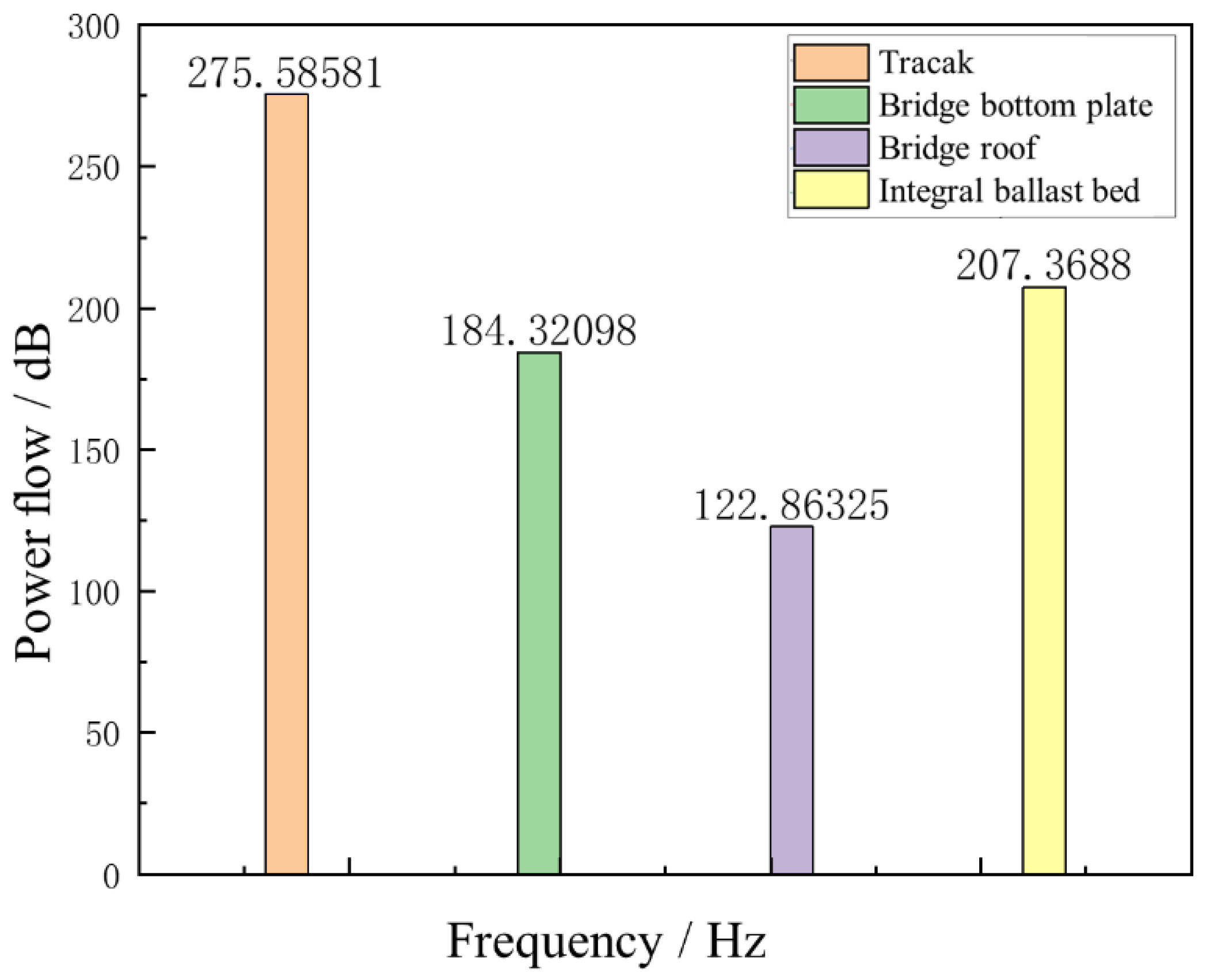
4.1. Analysis of Transmission Characteristics Based on Average Vibration Energy Level

Figure 7 illustrates the average vibration energy levels of the track, track bed, bridge roof, and floor of the box girder bridge. The power flows of these four components in the track structure are recorded as 275.59 dB, 207.37 dB, 184.32 dB, and 122.86 dB, respectively. The transmission rates of vibration energy from the track, integral ballast bed, box girder bridge roof, and box girder bridge floor are 75.2%, 88.9%, and 66.3%, respectively.
When considering the law of energy conservation, it becomes evident that 24.8% of the vibration energy from the common integral ballast bridge segment in urban track transit is stored in the fastener system. This portion of energy can significantly impact the wheel–track contact state and the service performance of fasteners.
Concurrently, 33.7% of the total vibration energy transmitted to the box girder bridge is retained within the box girder bridge. This stored vibration energy is subsequently converted into low-frequency noise within the bridge, influencing the acoustic environment along the urban track transit route.

4.2. Impact of Fastener Parameters on the Power Flow Transfer Rate of the Entire System

Figure 8 presents the power flow transfer rate between the components of the integral ballast bed for fastener stiffness values of 20 kN/mm, 40 kN/mm, and 60 kN/mm. The influence of fastener stiffness on power flow transfer varies across different frequency bands.
As shown in Figure 8a, in the frequency range of 0–100 Hz and 650–1600 Hz, the downward vibration energy transmitted by the track increases with the rise in fastener stiffness. However, within the 100–650 Hz frequency band, the power flow transfer of track strengthens as the design value of fastener stiffness decreases. This indicates that the stiffness design within this frequency band should not be excessively small, as it could weaken the damping effect of the fastener system.
Figure 8b shows that the impact of fastener stiffness on the power flow transfer rate from the ballast bed to the bridge roof primarily occurs in the frequency band above 700 Hz. Within the 100–700 Hz range, vibration energy transfers more readily downward with increasing fastener stiffness. However, in the frequency range of 700–1600 Hz, a smaller fastener stiffness results in a stronger power flow transfer efficiency.
Figure 8c shows that the influence of fastener stiffness on the power flow transfer rate in the box girder bridge is comparatively weaker than in the track structure. Fastener stiffness mainly affects the high-frequency transmission of the box girder bridge.
In summary, the stiffness of the fastener system significantly influences the vibration energy transfer within the integral ballast. Considering that the vibration noise of the bridge primarily concentrates in the low-frequency band, the fastener stiffness design should not be excessively small when considering the vibration noise suppression of the bridge.
Figure 9 illustrates the influence of the fastener system’s damping on the vibration energy transfer within the bridge system for fastener damping of 30 kN·s/m, 40 kN·s/m, and 50 kN·s/m.
As seen in Figure 9a, the damping of fasteners has minimal impact on the vibration energy transfer from the track to the ballast within the 0–650 Hz frequency range, with a more pronounced effect observed in the frequency band above 650 Hz. This suggests that greater damping in the fastener system promotes the transmission of high-frequency vibration energy.
From Figure 9b, it is evident that within the frequency band above 650 Hz, fastener damping exerts little influence on the energy transfer rate of the ballast bed to the bridge. However, during this period, vibration energy accumulates within the ballast bed, potentially affecting its service performance.
Figure 9c illustrates that fastener damping significantly affects the transfer of vibration energy within the box girder bridge. Within the 0–812 Hz damping range, the fastener damping is inversely proportional to the overall power flow transfer rate. This suggests that opting for fasteners with higher damping can attenuate the transfer of vibration energy within the box girder bridge. And this choice can effectively mitigate vibration noise within components such as the bottom plate and other structural elements of the box girder bridge.

5. Conclusions

This paper establishes the vehicle–track–bridge coupled dynamics model to systematically investigate the transmission patterns of vibration power flow induced by train operations within the track structure. The principal findings of this study can be summarized as follows.
(1)
The vibration energy caused by train operation in the low-frequency band is mainly concentrated in the integral ballast bed and the bridge roof and bottom plate of the box girder bridge. Most of the vibration energy will accumulate in the ballast bed. The vibration energy in the middle- and high-frequency band is mainly concentrated in the track position.
(2)
The fastener system, as the main vibration reduction component of the ordinary integral ballast, has a greater impact on the power flow in the low frequency range. Strategically reducing the stiffness of fasteners can effectively attenuate the transmission of low-frequency vibrations to the bridge, consequently leading to a reduction in the low-frequency vibrations experienced by the bridge structure. In the range of middle and low frequency, the accumulation of vibration energy of ballast decreases with the increase in damping of the fastener. However, with the increase in frequency, the accumulation state of vibration energy of the ballast bed and bridge will be intensified.
(3)
The fastener is the vibration reduction component of the ordinary integral ballast bed. In order to reduce the vibration and noise of the bridge on the bridge line, it is recommended to set the stiffness and damping of the fastener to 40 kN/mm and 50 kN·s/m, respectively.
Based on the above conclusions, future studies can apply the vibration power flow research method to different forms of urban rail transit track structures, such as flexible long sleeper tracks, steel-spring floating-plate tracks, and trapezoidal sleeper tracks. Vibration power flow studies can also be conducted on other modes of rail transport, such as high-speed railways, intercity railways, and urban light railways.

Author Contributions

X.C., L.Y. and X.Z.: methodology. P.L.: software. J.X.: validation. X.C. and L.Y.: formal analysis. L.Y.: data curation. X.Z., L.Y. and P.L.: writing—original draft preparation. X.C. and J.X.: writing—review and editing. All authors have read and agreed to the published version of the manuscript.

Funding

This research was funded by the National Natural Science Foundation of China (NSFC) grant number 52362049; the Natural Science Foundation of Gansu Province, grant numbers 22JR11RA152 and 22JR5RA344; The Joint Innovation Fund Project of Lanzhou Jiaotong University and Tianjin University, grant number 2022063; The Young Doctor Foundation Education Department of Gansu Province, grant number 2023QB-037; Lanzhou Science and Technology Planning Project, grant number 2022-ZD-131; Gansu Province Outstanding Graduate Innovation Star Project, grant number 2023CXZX-517.

Institutional Review Board Statement

Not applicable.

Informed Consent Statement

Not applicable.

Data Availability Statement

The data used to support the findings of this study are available from the corresponding author upon request. The data are not publicly available due to privacy.

Conflicts of Interest

Author Peixuan Li is employed by the CRRC Zhuzhou Institute Co., Ltd. The remaining authors declare that the research was conducted in the absence of any commercial or financial relationships that could be construed as a potential conflict of interest.

References

  1. Liu, L.; Song, R.; Zhou, Y.-L.; Qin, J. Noise and vibration mitigation performance of damping pad under CRTS-III ballastless track in high speed rail viaduct. KSCE J. Civil. Eng. 2019, 23, 3525–3534. [Google Scholar] [CrossRef]
  2. Zhao, C.; Shi, D.; Zheng, J.; Niu, Y.; Wang, P. New floating slab track isolator for vibration reduction using particle damping vibration absorption and bandgap vibration resistance. Constr. Build. Mater. 2022, 336, 127561. [Google Scholar] [CrossRef]
  3. Yu, J.; Zhou, W.; Jiang, L.; Peng, K.; Zu, L. Train effect on the vibration behavior of high-speed railway track-bridge system subjected to seismic excitation. Soil Dyn. Earthq. Eng. 2023, 172, 108049. [Google Scholar] [CrossRef]
  4. Zhao, C.; Liu, D.; Zhang, X.; Yi, Q.; Wang, L.; Wang, P. Influence of vibration isolator failure on vehicle operation performance and floating slab track structure vibration reduction effectiveness. Shock. Vib. 2019, 2019, 8385310. [Google Scholar] [CrossRef]
  5. Zhou, X. Numerical analysis of influence of different track structures on vibration response of subway. Therm. Sci. 2020, 24, 1537–1543. [Google Scholar] [CrossRef]
  6. König, P.; Salcher, P.; Adam, C.; Hirzinger, B. Dynamic analysis of railway bridges exposed to high-speed trains considering the vehicle–track–bridge–soil interaction. Acta Mech. 2021, 232, 4583–4608. [Google Scholar] [CrossRef]
  7. Goyder, H.; White, R. Vibrational power flow from machines into built-up structures, part I: Introduction and approximate analyses of beam and plate-like foundations. J. Sound Vib. 1980, 68, 59–75. [Google Scholar] [CrossRef]
  8. Goyder, H.; White, R. Vibrational power flow from machines into built-up structures, part II: Wave propagation and power flow in beam-stiffened plates. J. Sound Vib. 1980, 68, 77–96. [Google Scholar] [CrossRef]
  9. Goyder, H.; White, R. Vibrational power flow from machines into built-up structures, part III: Power flow through isolation systems. J. Sound Vib. 1980, 68, 97–117. [Google Scholar] [CrossRef]
  10. Zhang, Y.; Zhou, L.; Wang, S.; Chen, L.-Q. Vibration power flow characteristics of the whole-spacecraft with a nonlinear energy sink. J. Low Freq. Noise Vib. Act. Control 2019, 38, 341–351. [Google Scholar] [CrossRef]
  11. Yang, Y.; Pan, G.; Yin, S.; Yuan, Y. Vibration transmission path analysis of underwater vehicle power plant based on TPA power flow. Proc. Inst. Mech. Eng. Part M J. Eng. Marit. Environ. 2022, 236, 150–159. [Google Scholar] [CrossRef]
  12. Dai, W.; Shi, B.; Yang, J.; Zhu, X.; Li, T. Enhanced suppression of longitudinal vibration transmission in propulsion shaft system using nonlinear tuned mass damper inerter. J. Vib. Control 2023, 29, 2528–2538. [Google Scholar] [CrossRef]
  13. Fu, N.; Zhao, Z.; Liu, Y.; Li, Y. Vibrational Energy Properties of Twin-Block Ballastless Track with Anti-vibration Structure on Bridge by Power Flow Analysis. KSCE J. Civ. Eng. 2022, 26, 715–726. [Google Scholar] [CrossRef]
  14. Sudheesh, K.; Sujatha, C.; Krishnapillai, S. Vibration power flow analysis of simply supported uniform beams under moving point loads. Int. J. Dyn. Control 2023, 11, 1–16. [Google Scholar] [CrossRef]
  15. Ghangale, D.; Arcos, R.; Clot, A.; Cayero, J.; Romeu, J. A methodology based on 2.5D FEM-BEM for the evaluation of the vibration energy flow radiated by underground railway infrastructures. Tunn. Undergr. Space Technol. 2020, 101, 103392. [Google Scholar] [CrossRef]
  16. Zhai, W.; Xia, H.; Cai, C.; Gao, M.; Li, X.; Guo, X.; Zhang, N.; Wang, K. High-speed train–track–bridge dynamic interactions—Part I: Theoretical model and numerical simulation. Int. J. Rail Transp. 2013, 1, 3–24. [Google Scholar] [CrossRef]
  17. Zhai, W.; Han, Z.; Chen, Z.; Ling, L.; Zhu, S. Train–track–bridge dynamic interaction: A state-of-the-art review. Veh. Syst. Dyn. 2019, 57, 984–1027. [Google Scholar] [CrossRef]
  18. Zhang, X.; Li, X.; Wen, Z.; Zhao, Y. Numerical and experimental investigation into the mid- and high-frequency vibration behavior of a concrete box girder bridge induced by high-speed trains. J. Vib. Control 2018, 24, 5597–5609. [Google Scholar] [CrossRef]
  19. Li, X.; Zhang, X.; Zhang, Z.; Liu, Q.; Li, Y. Experimental research on noise emanating from concrete box-girder bridges on intercity railway lines. Proc. Inst. Mech. Eng. Part F J. Rail Rapid Transit. 2015, 229, 125–135. [Google Scholar] [CrossRef]
  20. Liang, L.; Li, X.; Yin, J.; Wang, D.; Gao, W.; Guo, Z. Vibration characteristics of damping pad floating slab on the long-span steel truss cable-stayed bridge in urban rail transit. Eng. Struct. 2019, 191, 92–103. [Google Scholar] [CrossRef]
Figure 1. Vehicle–railway–bridge coupling dynamics model.
Applsci 13 12543 g001
Figure 2. Track–integral ballast bed–bridge finite-element model.
Applsci 13 12543 g002
Figure 3. Numerical simulation utilizing the sixth-level spectrum of American railroads: (a) Random vertical irregularity of the left rail; (b) Random vertical irregularity of the right rail; (c) Random lateral irregularity of the left rail; (d) Random lateral irregularity of the right rail.
Applsci 13 12543 g003aApplsci 13 12543 g003b
Figure 4. Power flow of integral ballast bed.
Applsci 13 12543 g004
Figure 5. Power flow of track, integral ballast bed, bridge roof, and bridge bottom plate varies with the stiffness of coupler: (a) Power flow of track; (b) Power flow of integral ballast bed; (c) Power flow of bridge roof; (d) Power flow of bridge bottom plate.
Applsci 13 12543 g005
Figure 6. Power flow of track, integral ballast bed, bridge roof, and bridge floor varies with the damping of coupler: (a) Power flow of track; (b) Power flow of integral ballast bed; (c) Power flow of bridge roof; (d) Power flow of bridge bottom plate.
Applsci 13 12543 g006
Figure 7. Average vibration energy level of integral roadbed and box girder bridge.
Applsci 13 12543 g007
Figure 8. Impact of different fastener stiffness values on power flow transfer of the bridge system: (a) Power transfer rate from the track to overall ballast with different fastener stiffness values; (b) Power transfer rate form the integral ballast bed to the bridge roof with different fastener stiffness values; (c) Power flow transfer rate from the bridge roof to bridge bottom with different fastener stiffness values.
Applsci 13 12543 g008
Figure 9. Impact of different fastener damping levels on power flow transfer of the bridge system: (a) Power transfer rate from the track to overall ballast with different fastener damping levels; (b) Power transfer rate form the integral ballast bed to the bridge roof with different fastener damping levels; (c) Power flow transfer rate from the bridge roof to bridge bottom with different fastener damping levels.
Applsci 13 12543 g009
Table 1. Freedom of vehicle dynamics model.
Degrees of FreedomHang DownRise and FallNods
Train body Zcβc
Front bogie Zt1βt1
Rear bogie Zt2βt2
First wheelsetZw1-βw1
Second wheelsetZw2-βw2
Third wheelsetZw3-βw3
Fourth wheelsetZw4-βw4
Table 2. Numerical values of system dynamics parameters of subway A-type vehicle.
ParametersNumerical Value
Body mass/kg4.566 × 104
Height of vehicle center from track surface/m1.852
Vehicle fixing distance/m15.7
Quality of wheelsets/(kg·m2)1,985,110
Fixed wheelbase/m1093
Framing quality/kg2.5
Primary longitudinal/transverse/vertical damping2081
Two-system vertical/transverse/vertical damping (Ns/m)0/0/10,626
Axlebox spring longitudinal/transverse stiffness0/2.9 × 104/1.1 × 104
Wheel radius/m0.42
Traction tie rod longitudinal stiffness (N/m)4.16 × 106
Height of the upper plane of the gas spring from the track surface/m0.896
Torsion bar spring stiffness (N/m)2.5 × 106
Table 3. Track structural parameters and bridge structural parameters.
Track ComponentCell TypeCorrelation ParameterNumerical Value
TrackBeam188Cross-sectional moment of inertia/(m4)2.1 × 1011
Elastic modulus/(Pa)3.215 × 105
Poisson’s ratio0.3
FastenerCombin14Linear density/(kg·m−1)60.64
Stiffness/(N·m−1)4 × 107
Damp/(N·s·m−1)2.26 × 104
Integrated ballast bedSolid45Density/(kg·m−3)2251
Elastic modulus/GPa21
BridgeShell63Elastic modulus/Pa3 × 1010
Poisson’s ratio0.25
Density/(kg·m−3)2500
Disclaimer/Publisher’s Note: The statements, opinions and data contained in all publications are solely those of the individual author(s) and contributor(s) and not of MDPI and/or the editor(s). MDPI and/or the editor(s) disclaim responsibility for any injury to people or property resulting from any ideas, methods, instructions or products referred to in the content.

