Article

Energy-Dissipation Support Technology for Large Deformation Tunnels Based on the Post-Peak Behavior of Steel Plate Buckling: A Case Study

1
Graduate Department of China Academy of Railway Sciences, Beijing 100081, China
2
Key Laboratory of Transportation Tunnel Engineering of the Ministry of Education, Southwest Jiaotong University, Chengdu 610031, China
3
Chengdu Tianyou Tunnelkey Company Ltd., Chengdu 610031, China
*
Author to whom correspondence should be addressed.
Appl. Sci. 2023, 13(21), 11972; https://doi.org/10.3390/app132111972
Submission received: 4 September 2023 / Revised: 20 October 2023 / Accepted: 30 October 2023 / Published: 2 November 2023
(This article belongs to the Special Issue Tunneling and Underground Engineering: From Theories to Practices)

Abstract

:
Large deformations can easily occur when tunneling through weak surrounding rock with high underground stresses. Under high-stress environments, the surrounding rock stores a large amount of strain energy, and the strain energy stored in the soft and weak surrounding rock enclosure is dissipated through the large traveling plastic deformation. Therefore, the effective use of the surrounding rock’s bearing capacity and energy dissipation is a feasible solution to the large deformation problem. Based on the energy principle, this study designs a high compressibility, large stroke energy-dissipation element, which transforms the traditional support into energy-dissipation support and solves the problem of large deformation by reasonably utilizing the “displacement” of the surrounding rock. The experimental results showed that the steel plate assembled structure had an initial peak value of about 15 MPa, a constant resistance of about 2 MPa with a large stroke, and a compression rate of more than 75%, with good post-compression flexural peak characteristics. Elastic–plastic buckling analyses of defective steel plate composite structures were carried out using finite element analysis software, and the deformation and force characteristics of a variety of steel plate composite structures after buckling under actual field conditions were investigated. Based on the 3D laser scanning system, the thickness of the upper and lower steel plates of the steel plate composite structure was set to 1 cm, the height of the vertical plate was set to 28 cm, and the thickness was set to 8 mm. The original rigid supporting method was converted into one of compression support by circumferentially embedding the steel plate composite structure into the initial support structure. The resulting support configuration offered a high safety factor because the pressure of the surrounding rock was released by the deformation of the steel plate composite structure.

1. Introduction

The development of China’s economy and the continuous improvement in its transportation network have resulted in more need than ever for more tunnels to traverse complex geological environments. Specific topographical and geological conditions mean that tunnels are inevitably prone to significant deformation and other disasters when they pass through areas of soft rock mass, such as argillaceous rock and fracture zones. These not only present challenging difficulties during the construction period but also significantly increase the maintenance burden during their operational period [1].
At present, the mainstream idea in tunnel engineering design in a weak surrounding rock remains the concept of “strong support and timely support”, which inhibits the deformation of the surrounding rock by providing strong structural support [2]. Support structures with high stiffness can tolerate small degrees of deformation, and because it is difficult to fully release the energy stored in the surrounding rock, such support structures require high strength. Engineering practice has shown that this type of support method often fails to effectively solve the problem of significant deformation of soft rock and can only be successfully managed after multiple cycles of supporting intervention, damage, and demolition [3]. However, this design method has generated many serious problems in addition to not being economical, which has impaired the progress of projects. It has also required greater construction safety measures and presented additional problems when dismantling failed supporting members, such as concrete cracking, falling, and collapsing blocks caused by the demolition of the tunnel arch, as shown in Figure 1 below.
Following the incidence of numerous large-scale deformation problems, researchers gradually realized the importance of increasing deformation reserves or reducing the stiffness of the supporting structures to facilitate the release of the surrounding rock pressure and began to think about resolving the large-scale deformation issues from the perspective of energy absorption and dissipation. In the 1960s, Cook [4] was the first to propose the notion of energy support when studying rockburst difficulties in African gold mines. In the 1970s and 1980s, M.D.G. Salamon [5] enriched and perfected Cook’s theory of energy release rate, which systematically described the energy changes in underground caverns during gradual excavation and gave the energy balance equation. Walsh [6] analyzed the law of change in energy form during the excavation process of underground caverns. Lai Yingde et al. [7] studied the problem of energy redistribution and automatic energy compensation for the energy released by the surrounding rock and absorbed by the support. At the same time, a system based on the concept of “energy-dissipation support” had gradually begun to develop in China and abroad. Kovári [8] first proposed the concept of “yield control” type support. Anagnostou and Cantieni [9] pointed out that the only feasible way to deal with the problem of large-scale deformation of extruded surrounding rock was to adopt a supporting structure that allowed significant deformation to occur without ensuing damage and proposed the method of constructing a “yield control” type of supporting structure. Zhou et al. [10] summarized the experimental support scheme attempted for deep and high in situ stress strata in Canada and contended that the ideal supporting structure should combine a high initial stiffness with a sound bearing capacity under large deformation conditions and flexibility.
In terms of energy support structures, the modus operandi can be divided into radial and circumferential flexible supports along the tunnel chamber. The radial flexible members are those placed between the steel frame and the surrounding rock, and the circumferential flexible members are those embedded between the steel frames. Their principle is the same: all of them are to make the support have a large deformable capacity and sustained bearing capacity so that it can maximize the absorption or dissipation of energy in the surrounding rock during the working process. In summary, from the earliest mines used in the swan body to the slidable steel frame, let pressure anchor, energy-absorbing anchors, etc., and then used in tunnels behind the support can be compressed to fill the layer, flexible support, let pressure support and other types of support. As early as 1923, Heise and Herbst [11] envisioned a support scheme in which a layer of round logs is filled between the U-frame and the surrounding rock or arranged in a circular pattern within the poured concrete lining, taking advantage of the low stiffness of the logs to allow for shrinkage to solve the problem of large deformations in the tunnel. Schächterle [12] proposed that in the context of expansive surrounding rock tunnels, compressible foundations should be constructed in the lining invert, following which a compressible filling layer should be set behind the arch. Aiming at the problem of cracking the soft rock tunnel lining, Wu and Shao [13] proposed a support scheme involving setting a flexible layer between the primary support and the secondary lining, but the deformation tolerance of this support model proved low. Meanwhile, He et al. [14] developed a constant resistance large deformation bolt capable of achieving up to a meter degree of deformation under a supporting force of 120–150 kN. Although this technology was found to be suitable for supporting both rock bursts and large-scale deformation, the processing costs and construction difficulties proved high. Bunar and Powondra [15] from Germany invented the Meypo pressure controller for tunnel ring setting and applied it to the Ibbenbüren coal mine in Germany. Although it achieved the expected results, it was difficult to popularize due to its high processing costs and construction difficulties. Experimental studies by Song et al. [16] showed that the stress distribution in the lining support is more uniform when radial tubular dampers are compactly arranged compared to the spaced arrangement. Based on the concept of combining rigidity and softness, Qiu et al. [17,18,19] developed a “rigid softness” type of support by adding ring direction-controllable compression members to the supporting structure, which effectively solved the problem of large-scale tunnel deformation. It is ideal for ensuring the long-term stability of tunnels, especially when there is no space for buffer deformation after the completion of the secondary lining [20].
In general, many scholars have carried out a lot of fruitful research on the support forms of large deformation tunnels with soft rock, but many new support forms have low applicability, low economy, and long duration. Currently, the main types of tunnel sections are circular, arched, and rectangular, with arched tunnels being the most common. The study of structural forces in tunnels is primarily conducted via theoretical analysis, finite element calculations, and on-site monitoring. In this paper, we investigate the large deformation of arched tunnels using finite element calculations and on-site monitoring. This study aims to break the traditional design concept of large deformation support for soft rock tunnels and to propose an efficient, safe, and low-cost measure to solve the problem of large deformation in tunnels. In this study, the law of energy conversion between surrounding rock and support system was analyzed, the conventional support method was optimized by using the sound plasticity and toughness properties of steel, the mechanical properties of molded members were tested by experiments and numerical calculations, and the role of the steel plate composite materials in the safe construction of tunnels in soft rock was verified by field examples.

2. Methodology

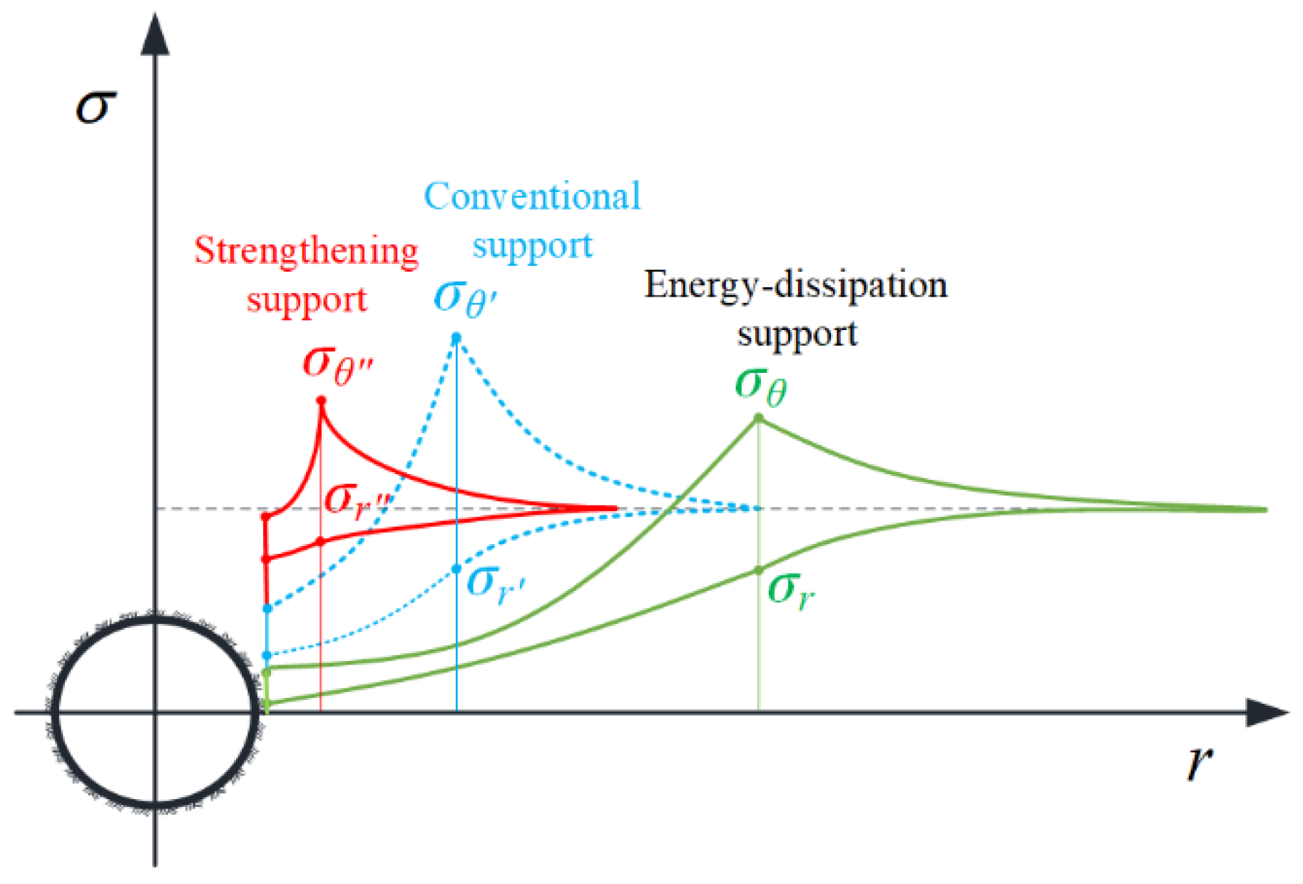
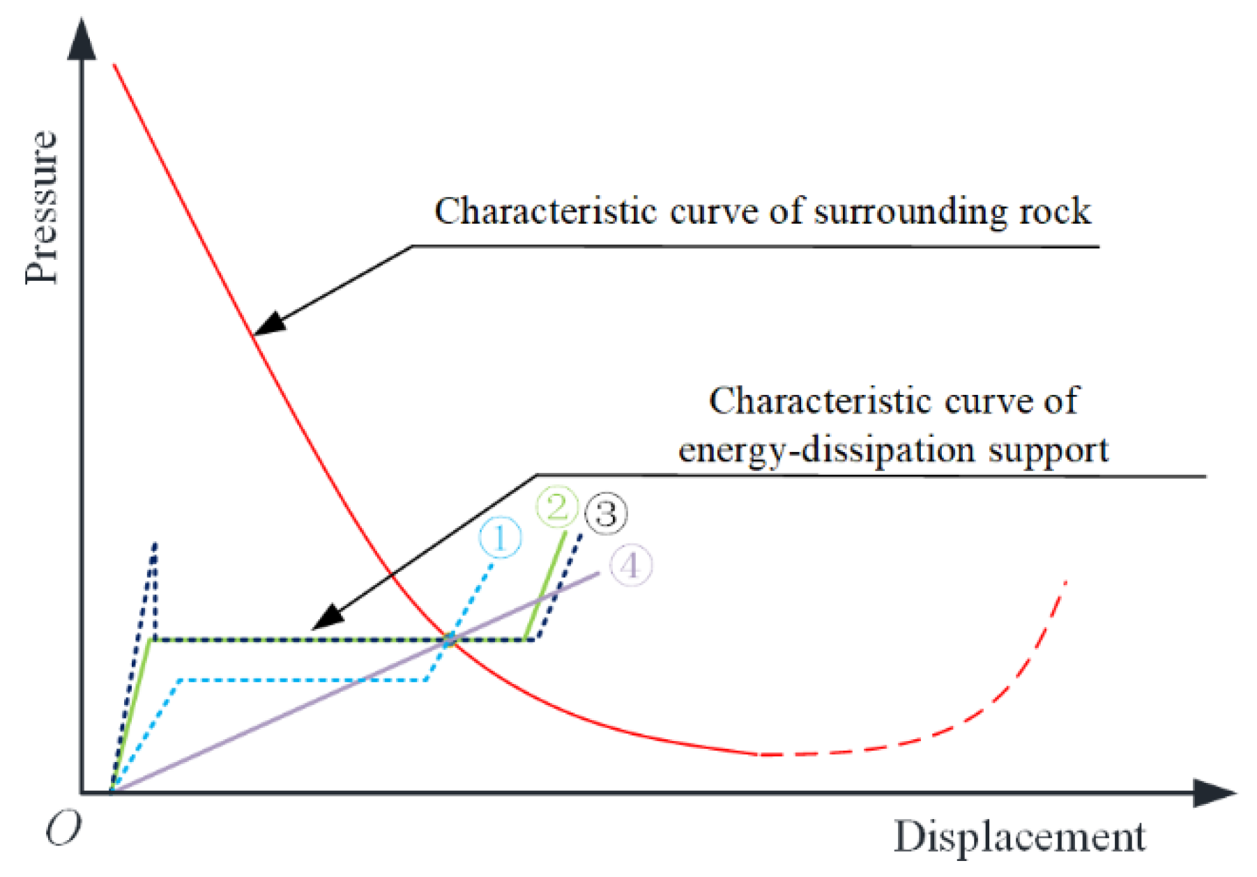
2.1. Design Concept of Energy-Dissipation Support

When constructing tunnels in soft surrounding rock, if the initial support of the tunnel should crack, the existing countermeasures primarily consist of installing an arch frame at the site of the support failure, removing the original support, and adopting the strengthening method. However, engineering practice has proved that the problem of cracking the supporting structure cannot be effectively solved by strengthening, which often involves multiple cycles of demolition and support measures. For example, in the cases of the Muzhailing Highway tunnel and Xinchengzi tunnel in China, it was necessary to adopt multiple arch modifications and to raise the support parameters to manage significant deformation. It nonetheless remained difficult to effectively solve the problem of damage to the supporting structure caused by large-scale deformation [21]. The objective of the repeated process of excavation and demolition cycles during construction is essentially to release the pressure of surrounding rock. This, however, also means being forced to accept the inevitability of the deformation of the surrounding rock. The stability of the supporting structure of the surrounding rock is dependent on the coordination between these two components, as shown in Figure 2 below. For this reason, merely relying on improving the strength of the supporting structure of tunnels in a high-energy geological environment is inadequate; hence, a new approach, method, and design are called for to achieve successful short- and long-term outcomes.
In a high in situ stress environment, significant levels of strain energy are stored in the surrounding rock, and the elastic strain energy stored in the soft surrounding rock is dissipated via the plastic deformation of a large stroke [19]. According to the law of mutual transmutation of energy, energy conversion in the broadest sense occurs via the coordinated combination of force and displacement. In the context of current tunnel design concepts, when dealing with large-scale soft rock deformation, the type of strengthening support often adopted consists of attempting to suppress the deformation of surrounding rock. In cases of small displacements, because the energy dissipation within the support structure and surrounding rock is very small, the energy accumulation process can only be expressed in the form of a “force”, and the supporting structure needs to provide a high resistance at that time. Therefore, when designing tunnels in soft surrounding rock, a change in thought processes is in the present authors’ view called for to realize that “force” is not the only means of addressing large-scale soft rock deformation and that the problem of large-scale deformation can be solved by rationally applying a method that capitalizes on the “displacement” of the surrounding rock.
To reasonably use the “displacement” of the surrounding rock to reduce the pressure within it, deformable tunnel ring supporting members were selected for the present study. Designing deformable elements within the steel frame transformed the original rigid support into an energy-dissipation support [22], as shown in Figure 3. According to the study [2], the energy transformation of the perimeter rock system is only related to the final equilibrium point of the perimeter rock-support characteristic curve, independent of the support path. The support characteristic curves of four types of let-pressure type support are listed in Figure ① is the support characteristic curve when the low constant resistance type of letting pressure support works, ② is the support characteristic curve when the high constant resistance type of letting pressure support works, ③ is the support characteristic curve when the constant resistance type of letting pressure support works with initial peak value, and ④ is the support characteristic curve when the low stiffness type of letting pressure support works. As can be observed, the four types of compression support in the Figure were found to achieve the same effect as that of the multiple excavation and demolition cycles of conventional support methods whilst providing enhanced support via their deformable characteristics. Based on providing minimal resistive support to guarantee the stability of the surrounding rock, the self-bearing capacity of the surrounding rock can be fully utilized by controlling the large-stroke deformation of the surrounding rock.
Compared to conventional support or enhanced support methods, the energy-dissipation support system was found to generate a certain degree of plastic deformation by controlling the surrounding rock, thus reducing the stress around the support and transferring the peak value of surrounding rock stress to a position farther away from the rock mass and the cavity, thus achieving a deep self-bearing effect, as shown in Figure 4, where σ is the stress of rock mass; r is the tunnel radius direction; σ θ is the tangential stress; and σ r is the radial stress.
Conventional support refers to the basic support measures used in the tunnel construction process. Conventional support mainly includes shotcrete lining, anchor support, steel arch, and so on.
Strengthening support is based on conventional support, for special geological conditions or design requirements, using more solid and strengthened support measures. Reinforced support usually includes reinforced support parameters, a double-layer steel frame, and so on.
Energy-dissipation support refers to letting the support structure have the ability of large deformation and deformation with the surrounding rock until the pressure of the rock body is released to the support structure can withstand the range.

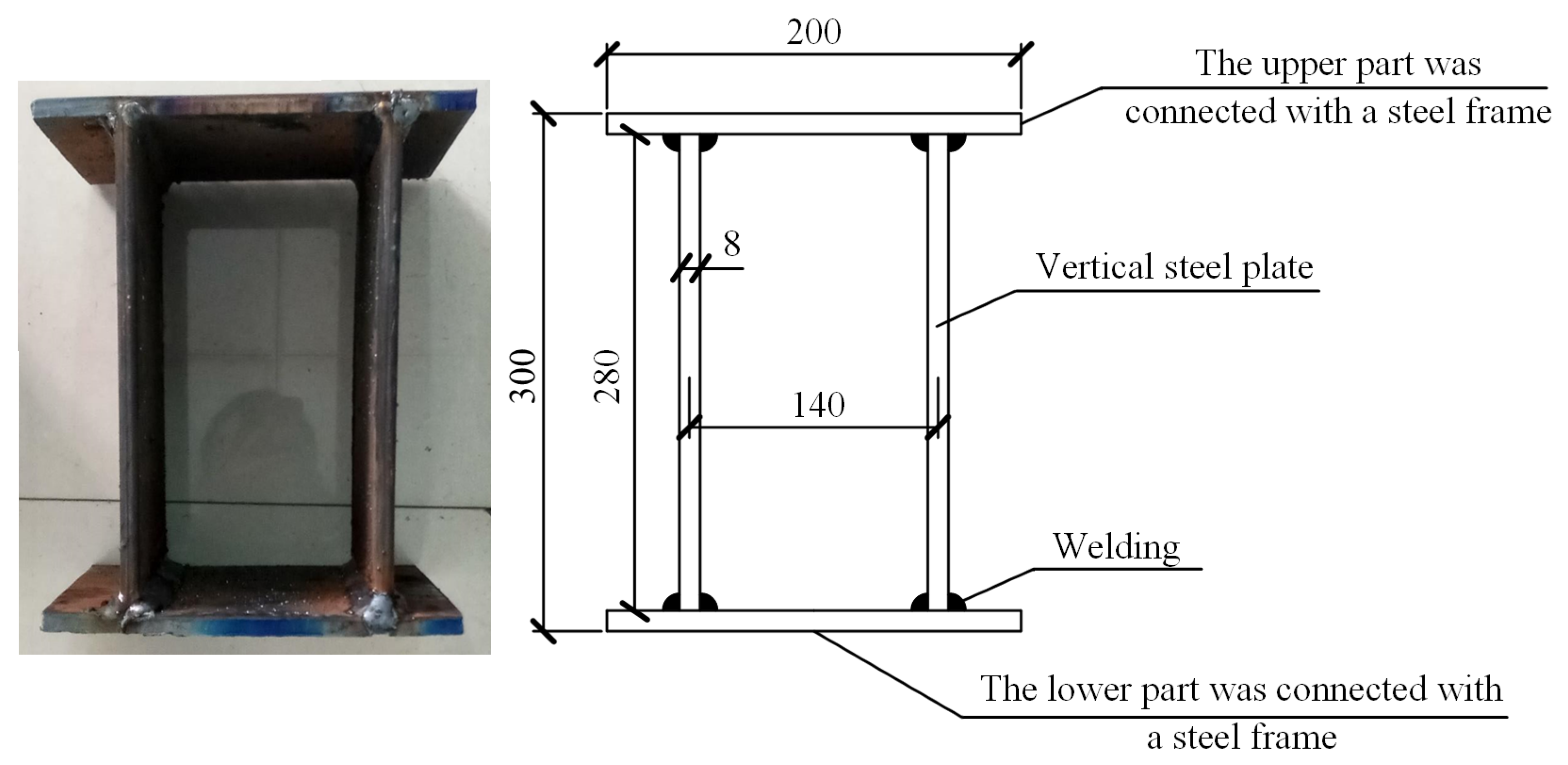
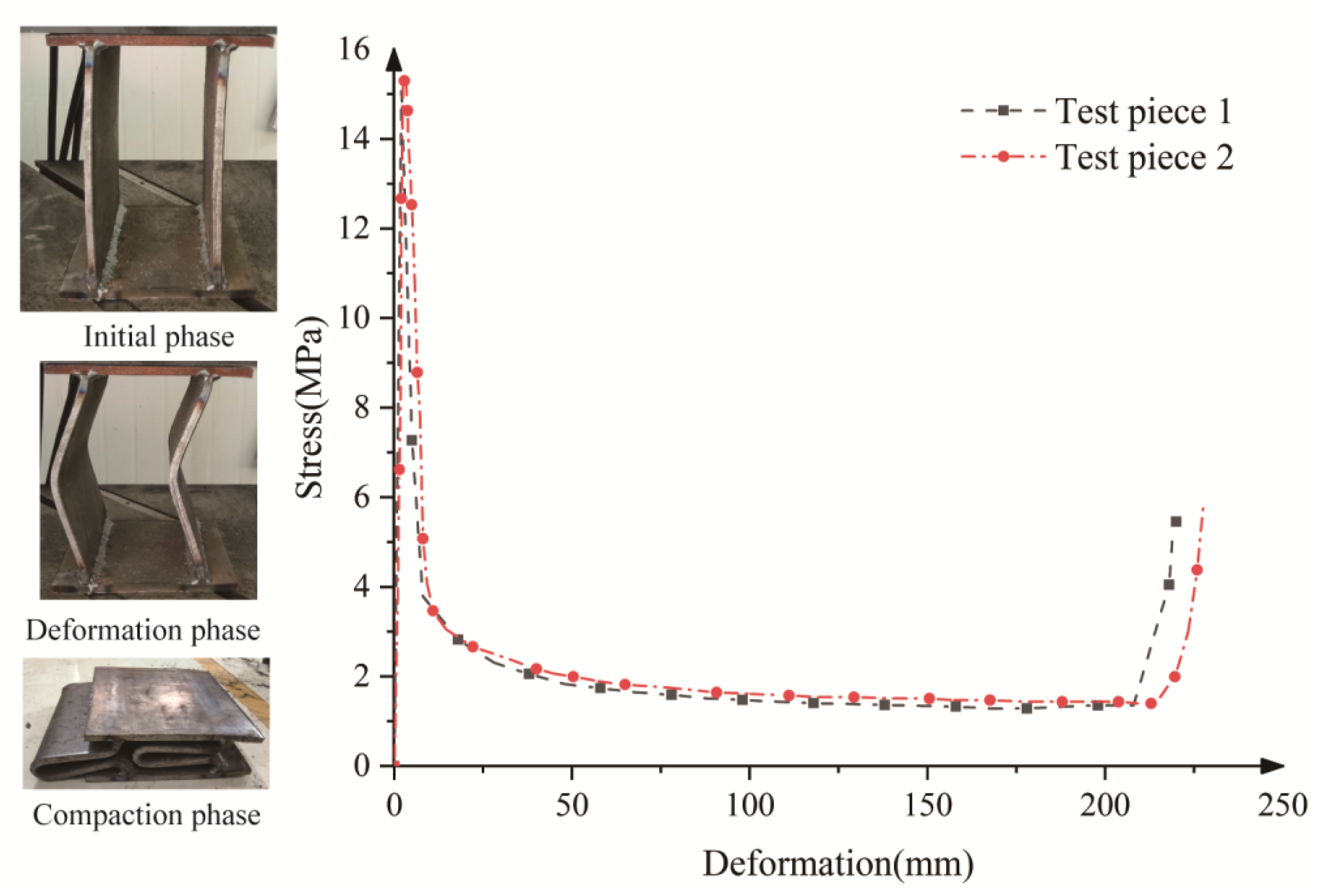
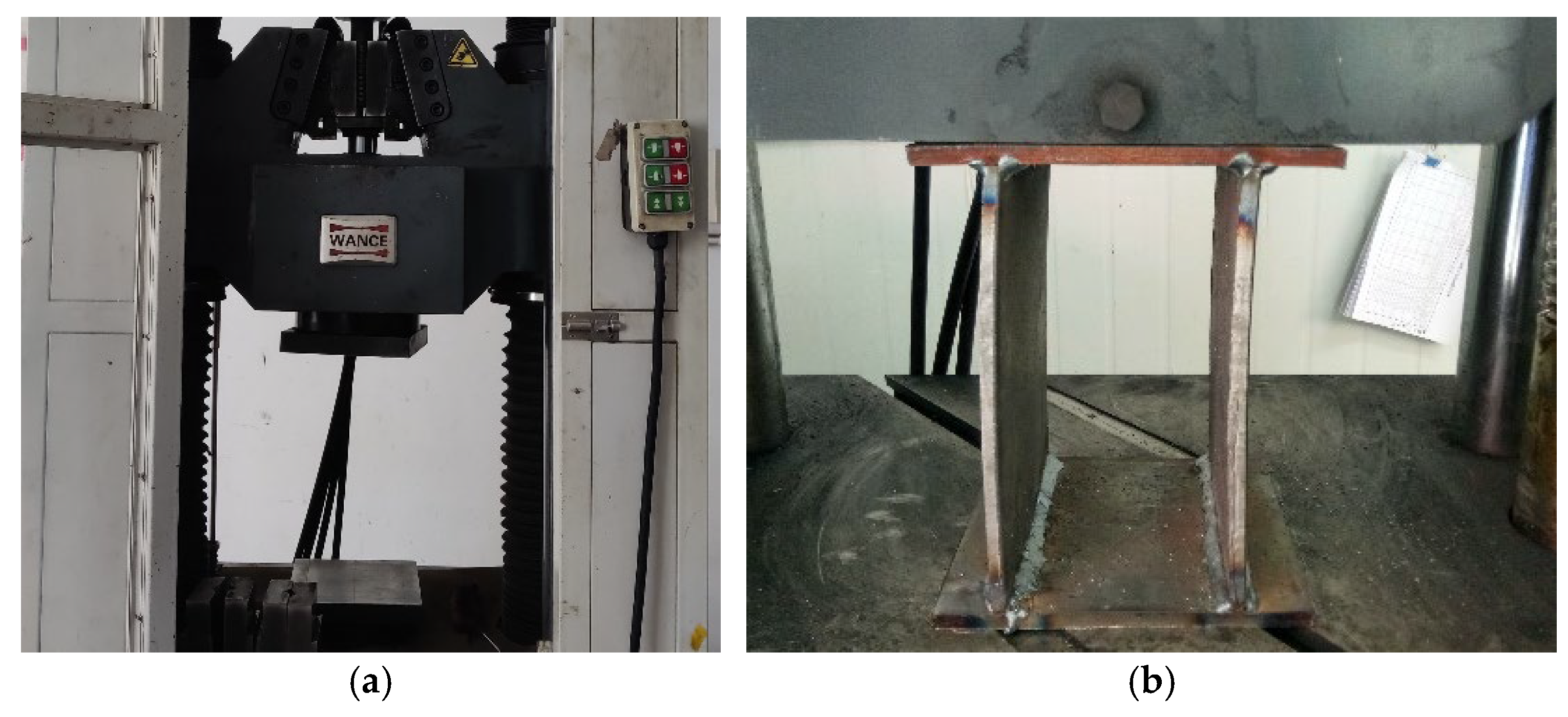
2.2. Model Testing of a Steel Plate Composite Structure

Steel is widely used in the construction of a range of public buildings due to its advantages of high strength, good plasticity and toughness, uniform material, good weldability, and a high degree of industrialization. It was therefore deemed possible in the present study to apply the principle of pressure bar stabilization or sheet buckling and to use sound post-peak bearing capacity and plastic deformation capability of steel to produce thin-walled steel plates as deformable tunnel ring supporting members and insert these into the tunnel support.
Considering that hot-rolled Q235B steel plates have been shown to offer both an excellent yield deformation capacity and post-peak residual load capacity [23], the steel plate materials in this study were designed in combination, and the resulting steel plate composite structure is shown in Figure 5 below. The vertical plate dimensions were 280 mm in height and 8 mm in thickness; the thickness of the upper and lower connecting steel plates was 10 mm.
When constructing tunnels with an arch structure in large-scale deformation settings, the stress the supporting structure is subjected to mainly consists of deformation pressure, which relates to the principle of rigid loading [24]. To verify the performance of the steel plate composite materials in this study, a WEW-1000 universal testing machine was used to carry out the rigid compression testing. The compression test of the steel plate composite structure involved displacement loading at a loading rate of 5 mm/min. The loading device is shown in Figure 6.
The deformation test of the steel plate composite structure is shown in Figure 7. It can be observed that the steel plate composite structure reached an initial peak of about 15 MPa, a constant resistance of about 2 MPa with a large stroke, and a compression of over 75%, which could fully dissipate the pressure of the surrounding rock. The initial peak value was able to prevent the large-scale deformation of the steel frame before the assembly was complete, which would have affected the assembly. Because the supporting structures of tunnels with an arch structure in large-scale deformation settings are mainly subjected to deformation pressure, which belongs to the principle of rigid loading, the application of steel plate composite structures to the construction of tunnels in soil prone to large-scale deformation was found not to produce instability [18]. It proved possible to solve the safety problem of large deformation tunnels by using a yielding structure. The steel plate composite structure was set on the steel frame so that the original rigid structure was transformed into a yielding structure so that the steel frame showed no signs of buckling or other damage in the deformation process.

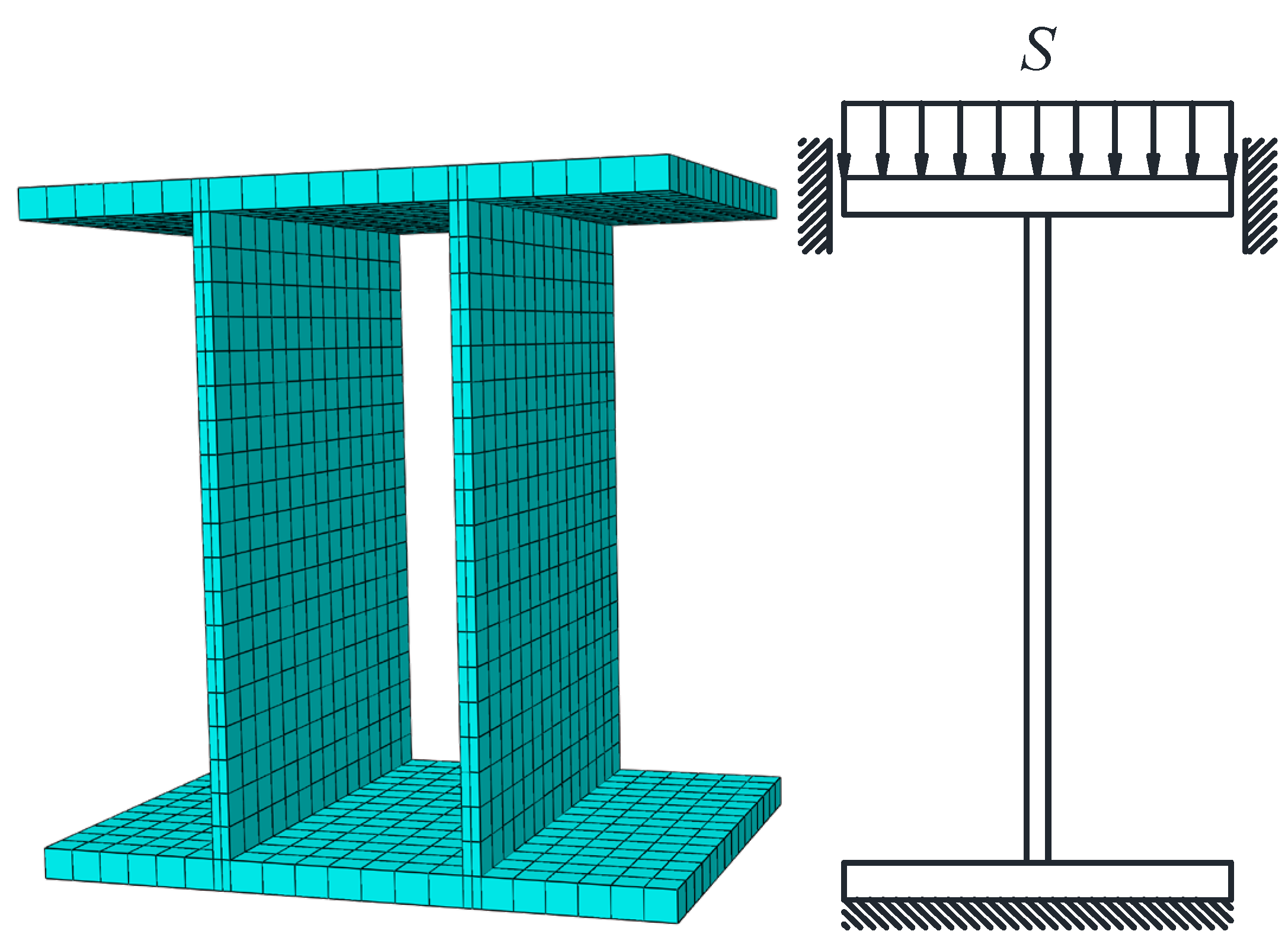
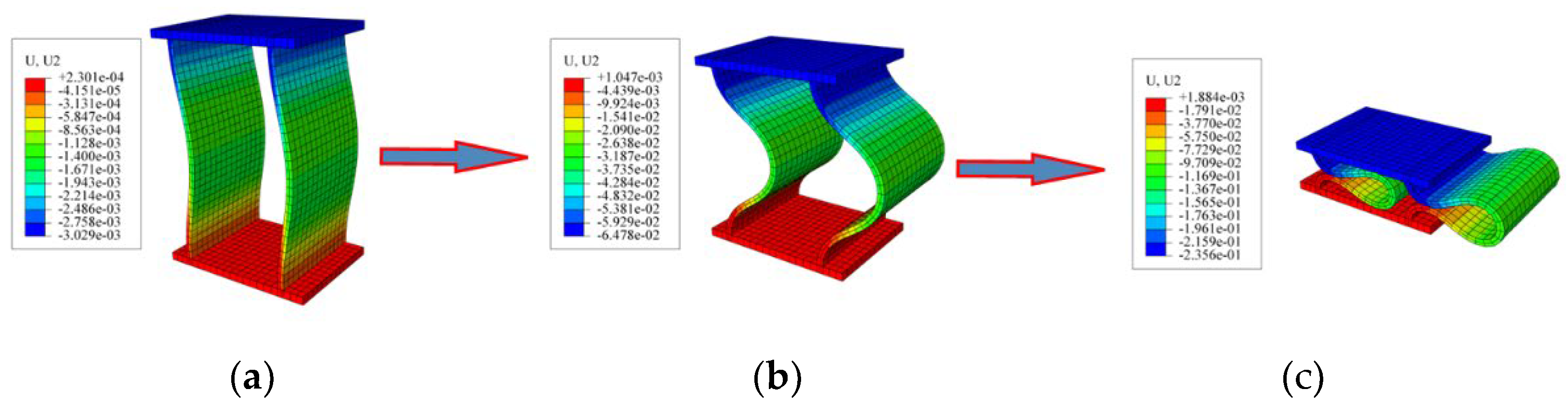
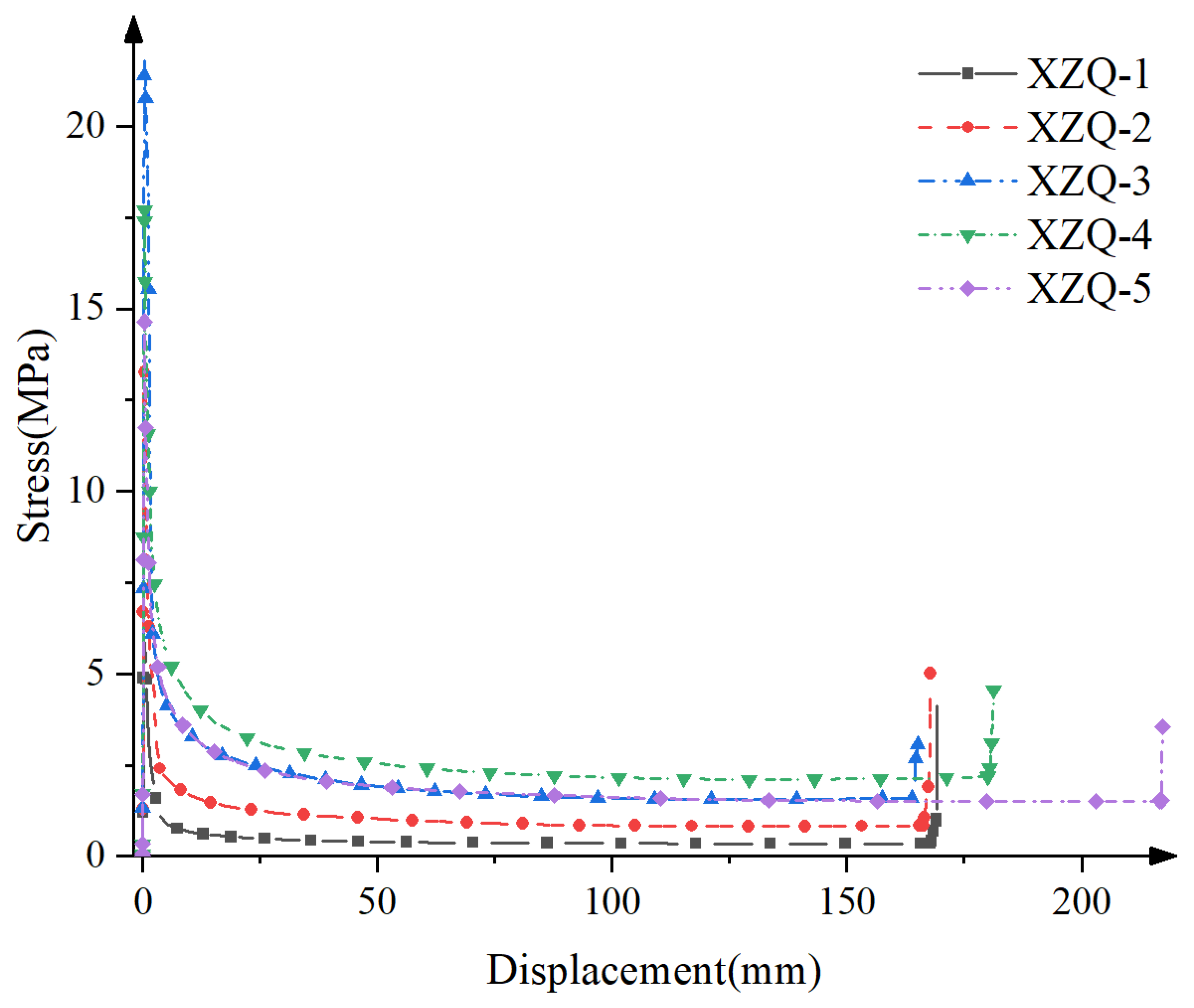
2.3. Numerical Simulation of the Steel Plate Composite Structure

Steel plate composite structures are affected by various factors, such as raw materials, welding conditions, and testing conditions. In this study, field application verification tests were conducted to verify the performance of the structures. Based on the field test results, finite element calculations were also performed to investigate the relationship between the initial peak value and the constant resistance value of the multi-specification steel plate composite structure. This study provides a solid foundation for the development and application of backward energy-dissipation supports. Imposing a vertical displacement constraint on top of the upper connecting steel plate set the constraint on both sides to slide vertically only. In addition, a fixed constraint was arranged at the bottom of the lower connecting steel plate. The unit is a hexahedral 20-node reduced integration unit, and to consider the post-flexion state, the vertical plate and the connecting plate are set to be in self-contact, the contact does not consider tangential friction, and the contact mode was set to “hard contact”, and the finite element analysis model is shown in Figure 8. Since the connecting plate is only a force transmission member, not the main body of analysis, and is connected with other materials in engineering applications, the upper connecting steel plate and the lower connecting steel plate were made of elastic material, and the vertical steel plate was made of elastic–plastic material, the calculated parameters of which are shown in Table 1. Vertical steel sheet material parameters are based on ex-factory parameters and the results of Versaillot P D et al.’s work on Q235 steel stress–strain curves [25], inverted from the average veneer constant resistance values obtained from the tests.
Since the performance of a steel plate composite structure is determined by its vertical steel plate, the required thickness and height of the latter were investigated as part of the present study, the calculation conditions of which are shown in Table 2 below.
The finite element model was established via ABAQUS, and the calculation was carried out according to the boundary conditions mentioned above. Selecting the same data as the numerical simulation for statistics, the finite element calculation results are shown in Figure 9. The compression of the steel plate type restrictor reaches more than 75%, has a large stroke, and can fully dissipate the pressure of the surrounding rock. Since the model material of numerical simulation is uniform, the result is relatively large, but the accuracy rate is more than 95%, which can be determined that the calculation method used is correct and reasonable, as shown in Table 3.
The stress–deformation curves of the steel plate composite structure under five working conditions are shown in Figure 10. Based on the validation test results, the working period of the steel plate composite structure can be divided into four main stages. The first stage is the elastic deformation stage, characterized by a linear increase in pressure with deformation. The second stage is the yielding down deformation stage, where the pressure decreases with deformation. The third stage is the yielding constant resistance deformation stage, where the pressure remains constant with deformation. This stage is considered the primary working stage for steel plate composite structure deformation, as it exhibits a significant stroke under constant pressure. The fourth stage is the compaction deformation stage, where the pressure sharply increases with deformation. It can be observed that while the initial peak value and constant resistance value of the vertical steel plate increased with the increase in thickness of the steel plate, the initial peak value and constant resistance decreased with the increase in height.

3. Case Study

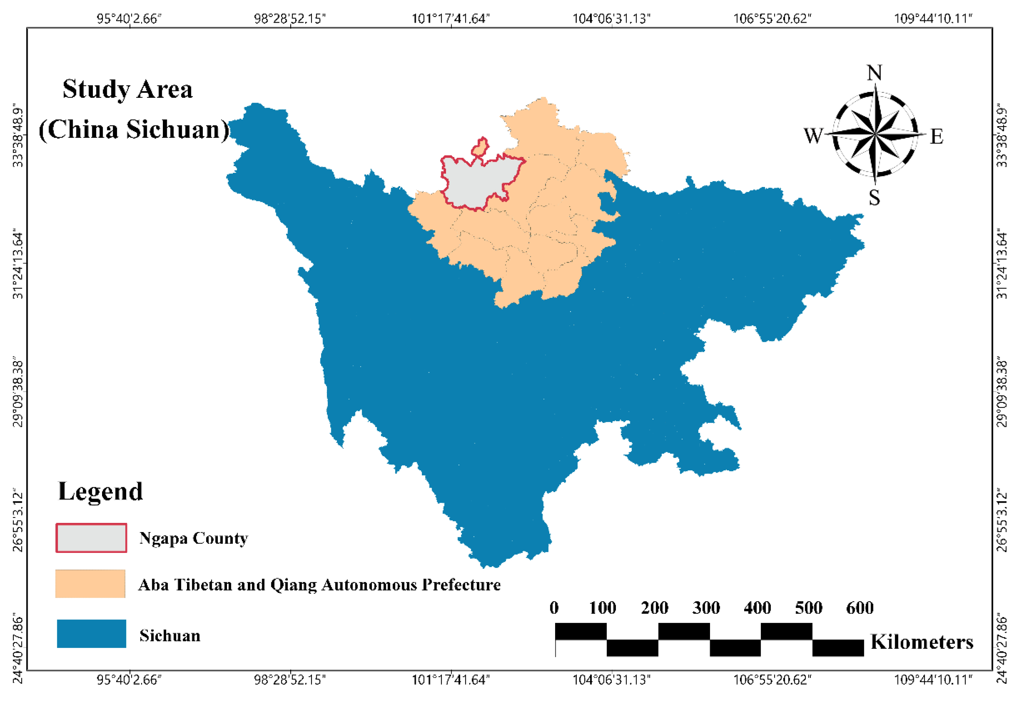
3.1. Overview of the Project

The Shenzuo tunnel is a key project of the Maerkang-Jiuzhi Expressway. The Maerkang-Jiuzhi Expressway, one of the important sections of the Dema Expressway, is an important corridor connecting the Chengdu Plain Economic Zone, the Qiang District of the Aba Tibetan Region, and Qinghai Province, as shown in Figure 11. The tunnel under construction in China had a complex geological structure and was subject to strong neo-tectonic movement. The survey area distribution includes accumulated Quaternary and Holocene landslide rock soil, residual silty clay slopes, and breccial and moraine stratum breccial soil. The underlying bedrock is Triassic middle dolomite limestone, lower sandy slate, slate, limestone, lamellar basalt, and fault breccia. According to geological prospecting data, the maximum stress in the tunnel body range was 19–38 MPa, and the lithology in the maximum buried depth of the tunnel was lamellar basalt, sandy slate, and limestone. According to the study’s experimental statistics, the compressive strength of the lamellar basalt was R = 23–43 MPa, and that of the limestone was Rc = 23–46 MPa, in which the values were deemed to belong to hard rock with a relatively developed structure, rich water, and local dryness. The strength and stress ratio of the surrounding rock was 1.15:1.65. He Manchao [26] proposed the concept of deep-engineered soft rock based on the nature of engineered rock bodies. According to the differences in the characteristics of engineered deep soft rock and the mechanism of generating significant plastic deformation, deep soft rock can be classified into four major categories, i.e., expansive deep soft rock, high-stress deep soft rock, jointed deep soft rock, and composite deep soft rock. In this study, significant plastic deformation occurred during the tunnel construction, which belongs to high-stress soft rock.
An I-22b steel frame with a spacing of 60 cm had been adopted in the original tunnel design. The thickness of sprayed C25 concrete was 28 cm, and a 22-connection steel frame was used longitudinally, 80 cm in length and a ring spacing of 100 cm. Continuous large-scale deformation occurred during the original tunnel construction, which resulted in a series of safety problems such as cracking of the initial support structure, buckling of I-beams, and cracking and falling of concrete blocks in the second lining side wall. A partial collapse had occurred during demolition, resulting in many workers sustaining injuries. To ensure construction safety and engineering quality, reinforced support and double- or triple-layer arches were adopted during remedial strengthening works, despite which concrete collapsing and steel frame buckling continued to take place, as shown in Figure 12.

3.2. Energy-Dissipation Support Design

It was essential, when designing the steel plate composite structure, to consider the characteristics of the project itself, and it was deemed necessary to employ a 3D laser scanner to assist with the design. This was used to monitor the holographic geometric parameters, which could, in turn, determine the deformation distribution values along the tunnel circumference, provide quantitative feedback for the reserved design to address the deformation, predict the deformation trend, and evaluate safety risks. Three-dimensional laser scanning has proved beneficial in improving construction quality, controlling construction costs, and ensuring on-site safety [27]. The scanned point cloud is shown in Figure 11 above. The most interesting section of data extracted from the 3D cloud map is shown in Figure 13. The left-side deformation is significantly higher than the right-side deformation, and there is a clear bias situation. As previously indicated, the original support design had failed to solve the problem of large-scale deformation, and once the overall structure had been damaged, the deformation magnitude increased sharply, presenting a risk of collapse of the tunnel, which severely augmented the site safety risks for personnel and machinery.
The specific scheme of the compression support design in this study was as follows: the supporting parameters of I-22b were maintained unchanged, two groups of steel plate combination structures were set at 25° around the vault, the left side was 37.8 cm high, the right side was 30.8 cm high, with a 40 cm reserve for further deformation. The thickness of the upper and lower steel plates was 1 cm, the height of the vertical plate was 28 cm, and its thickness was 8 mm. The composite structure of the steel plate and I-beam steel frame were connected by bolts, as shown in Figure 14.

3.3. Effects of Applying an Energy-Dissipation Support

3.3.1. Support Application Status

The construction of the energy-dissipation support was carried out in the large-scale deformation section of the tunnel, and the effect of the supporting work is shown in Figure 15a. According to the figure, once the initial support deformation had stabilized, the steel plate composite structure was still not fully compacted, and according to the compression curve, the steel plate composite structure was at the constant resistance stage. This indicated that the surrounding rock pressure had fallen to a level that the existing support structures could bear and that the characteristic curve of the surrounding rock intersected that of the support, signifying that the supporting structure had reached a stable state. No safety problems arose during construction, and the support effect is shown in Figure 15.
It was found that, compared to conventional support sections, the experimental pressure type support could effectively alleviate the phenomena of initial support cracking and concrete block dropping. The steel plate composite structure incurred significant deformation as part of the tunnel excavation support, but the overall state of the support structure remained sound, which indicated that the release of deformation pressure from the surrounding rock via controlled deformation in the highland rock stress area was conducive to the stability of the structure and the convergence of deformation.

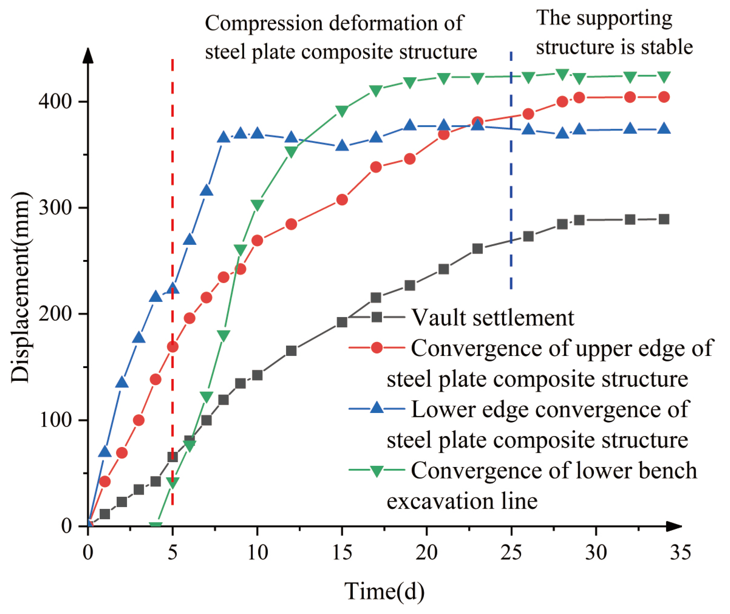
3.3.2. Support Deformation

To study the construction deformation of the energy-dissipation support, the aforementioned 3D laser scanning system was used to monitor the holographic deformation of the initial support, with the corresponding monitoring grayscale diagram shown in Figure 16. Limited by space, the section with the largest deformation was selected for analysis, and the support time-displacement curve of key points was drawn, as shown in Figure 17.
It can be seen from Figure 15 that the supporting deformation rate is relatively large from 0 to 10 days. With the deformation of the steel plate composite structure, the deformation rate of the support decreases gradually and eventually stabilizes after 25 days. Lastly, the deformation of the vault was 289.25 mm; that of the upper border of the steel plate composite structure was 404.38 mm; and that of the lower border of the same was 373.76 mm. The convergence deformation of the lower bench excavation line was 424.55 mm.

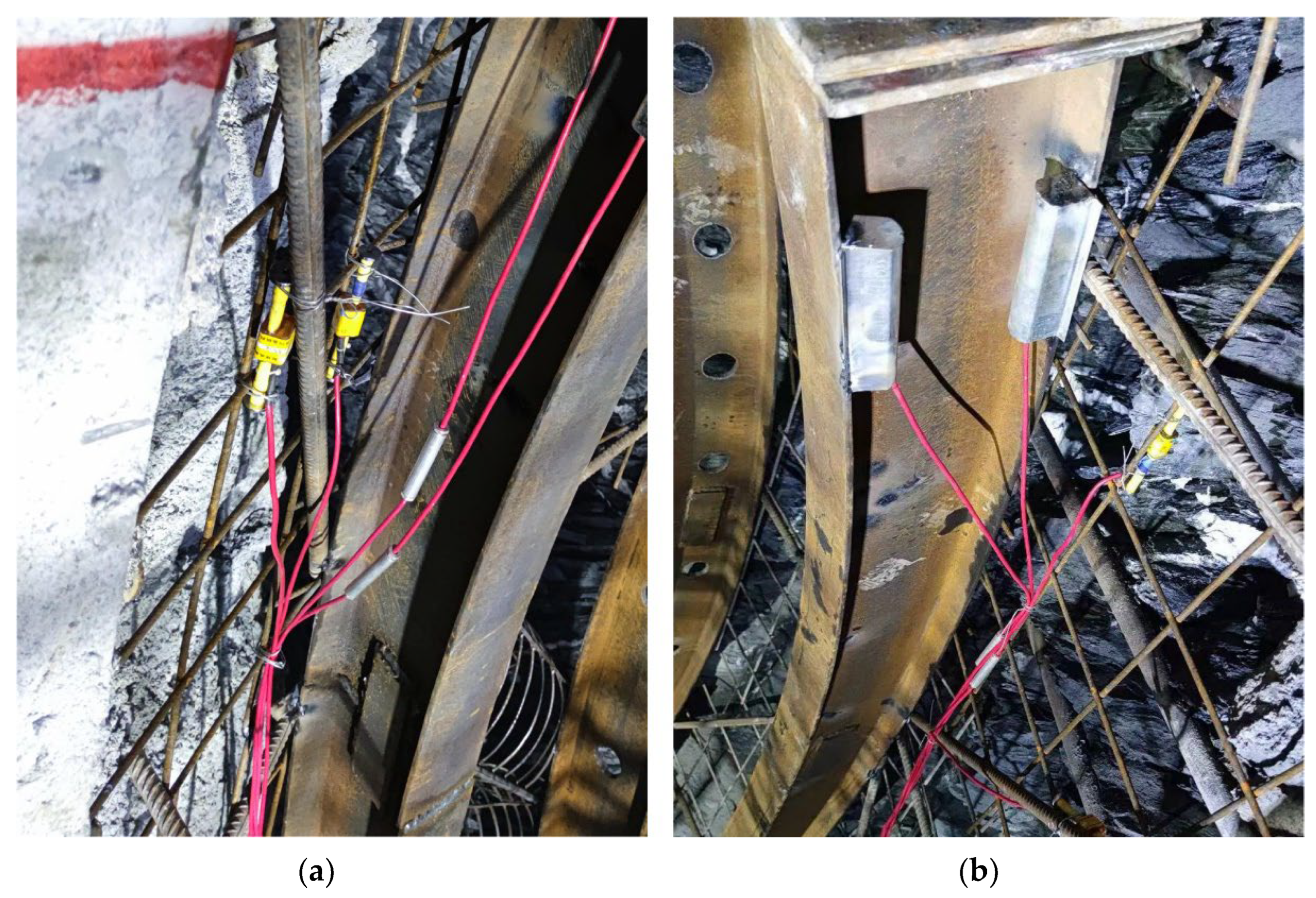
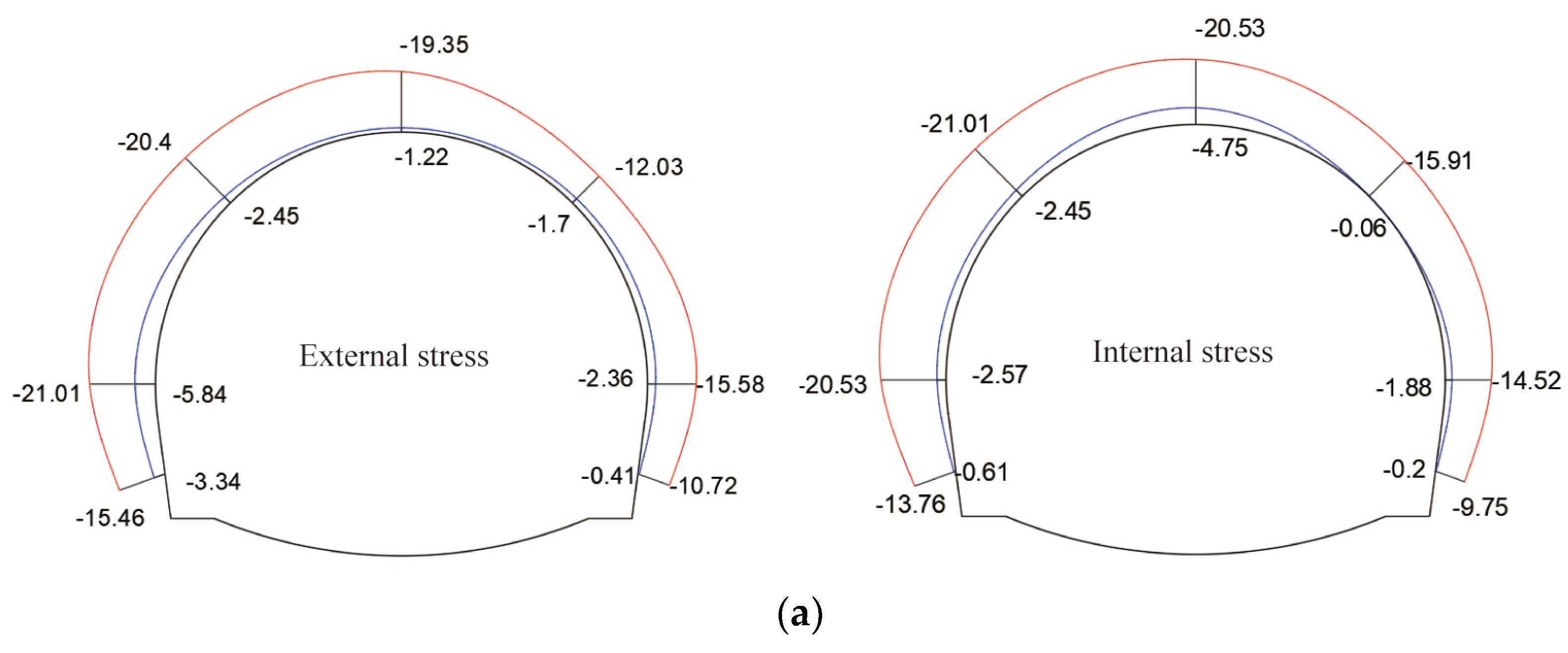
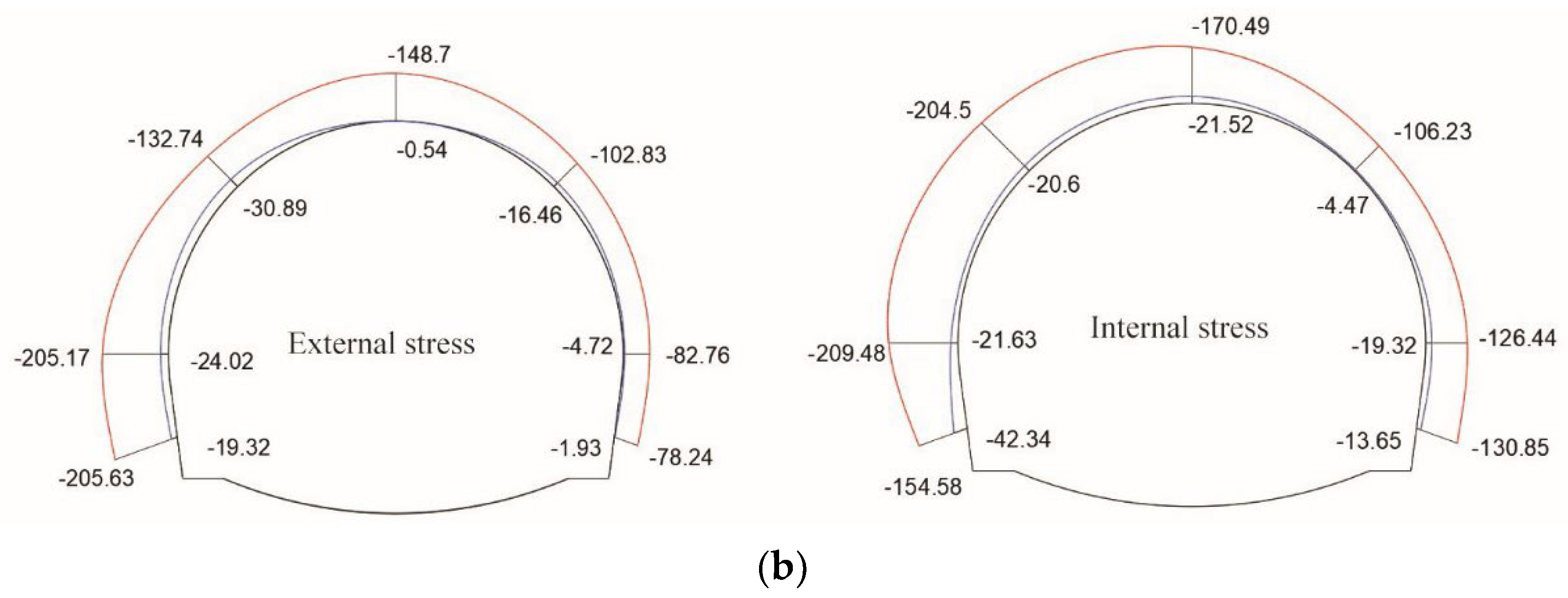
3.3.3. Support Stress Condition

To study the stress state of the energy-dissipation support, the embedded strain gauge was used for measurement, As shown in Figure 18. The final stress envelope diagram of the four test sections during the construction of the molding support is shown in Figure 19. The supporting internal force includes the stress of the headroom side and the surrounding rock side of the main reinforcement of the shotcrete and steel frame, where the value is negative under pressure and positive under tension; the blue line is the minimum value measured at each part, and the red line is the maximum value.
From the above stress envelope diagrams of the concrete and steel frame, it can be seen that the supporting structure was in a state of full section compression, meaning that it was in a state of low eccentric compression. The stress on the left side of the supporting structure was generally greater than that on the right side, indicating the presence of bias. The maximum stress value of shotcrete was 21.01 MPa, which was below the design value of compressive strength of C25 shotcrete. The maximum stress value of the steel frame was 209.48 MPa, which confirmed that the supporting structure offered a high safety score and that opting for a yield type of support guaranteed safety during construction.

4. Conclusions

To deal with key site safety problems during the construction of tunnels in soft rock environments, such as lining damage caused by large-scale soft rock deformation, this study proposed a steel plate composite supporting structure based on the behavior of steel plate buckling. This structure was installed circumferentially, relying on steel frames to transform a rigid support structure into a yielding alternative capable of solving the problem of large-scale deformation. The feasibility of designing such a structure was established by researching model testing and experimental field construction; the following conclusions were drawn:
(1)
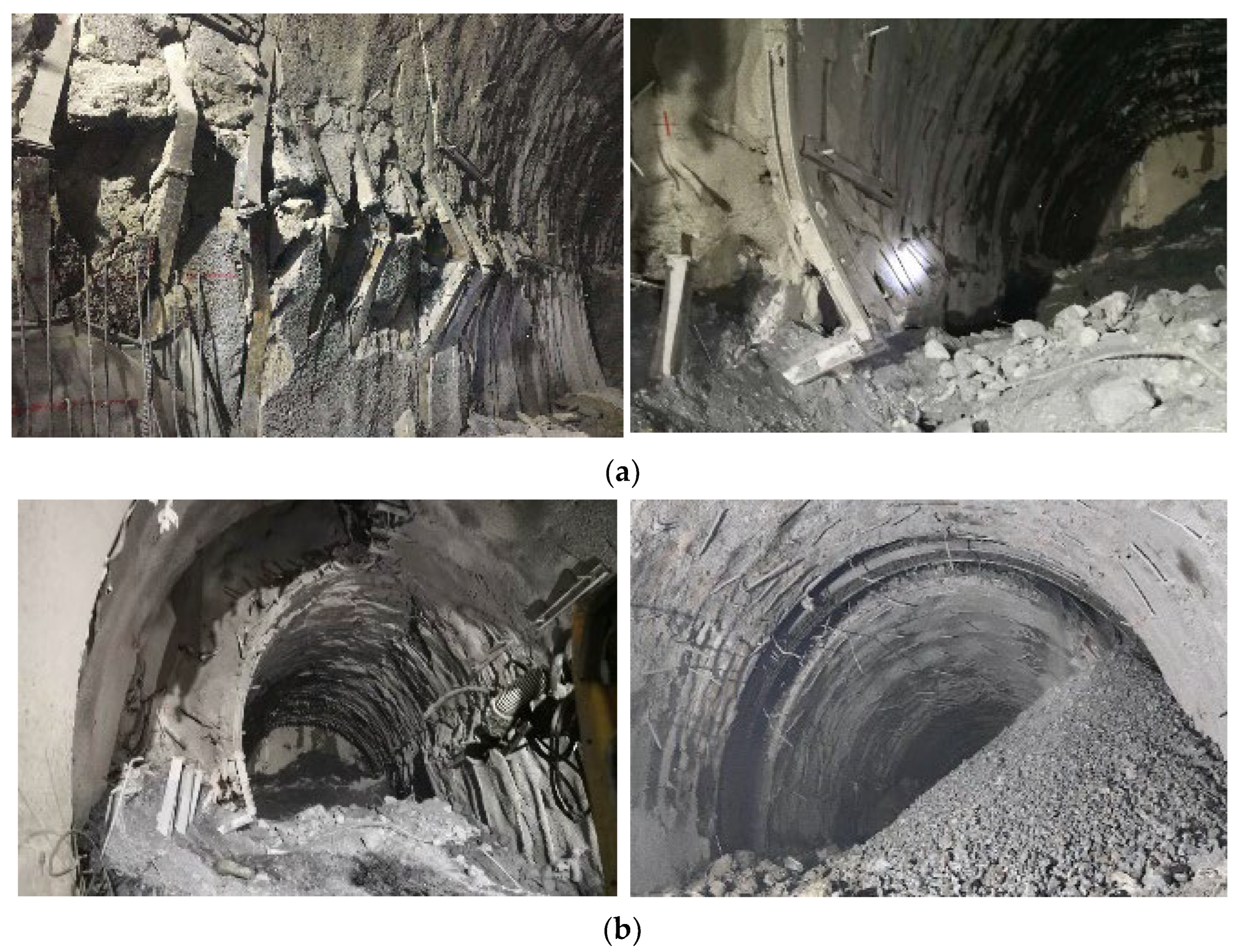
For tunnels in the weak surrounding rock, it is often not possible to pass conventional or strengthening support structures via the available space at any one time, resulting in the need for multiple replacements and supporting works, which in turn presents a series of construction risks. To deal with the safety problems caused by the large-scale deformation of soft rock, it is necessary to optimize the supporting structure. According to the characteristic curve law of surrounding rock, under the condition of providing a degree of supporting resistance, the pressure of the surrounding rock gradually decreases with the deformation of the surrounding rock. Therefore, a deformable support design could be investigated to reduce the pressure of the surrounding rock and reduce its pressure, and finally, solve the problem of large-scale deformation of soft rock.
(2)
A steel plate composite structure was designed after studying the properties of Q235B steel. According to the statistical results, it can be seen that the compression of the steel plate type restrictor reaches more than 75%, which has a high compressibility. The design of the steel plate composite structure is adaptable and can be designed according to the specific requirements of the site for the initial peak and constant resistance values.
(3)
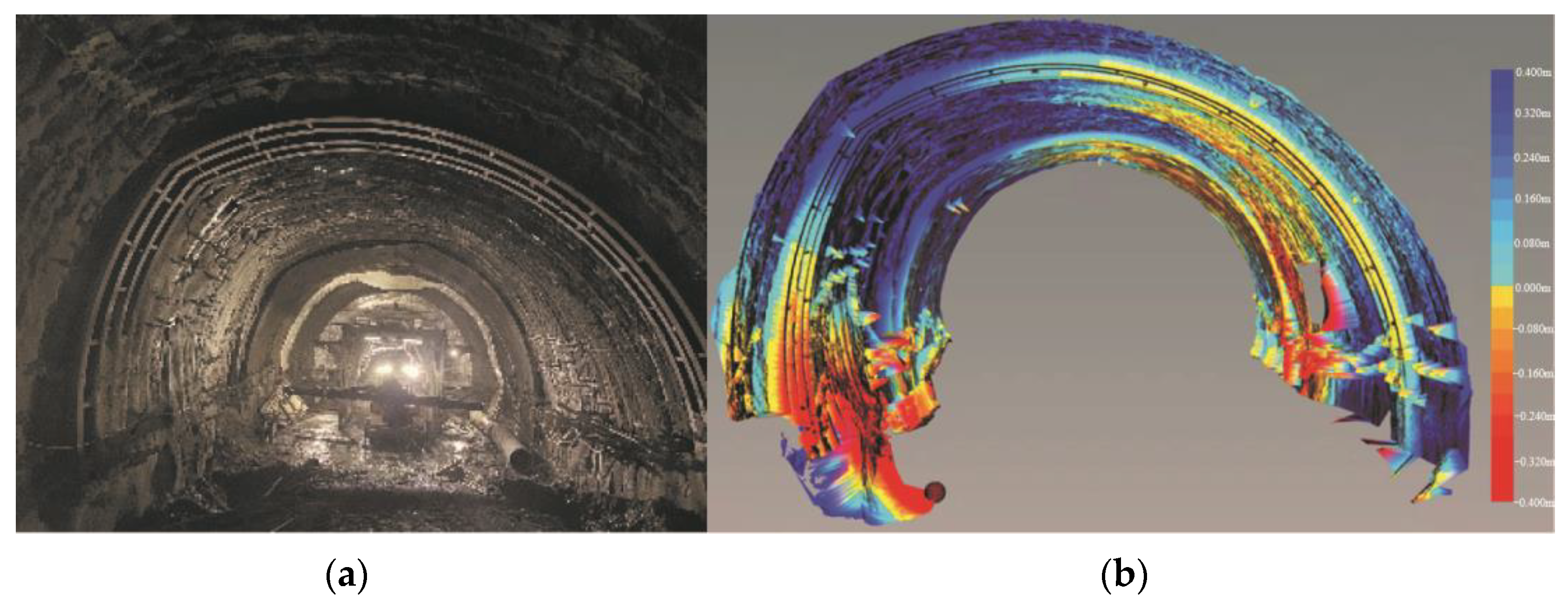
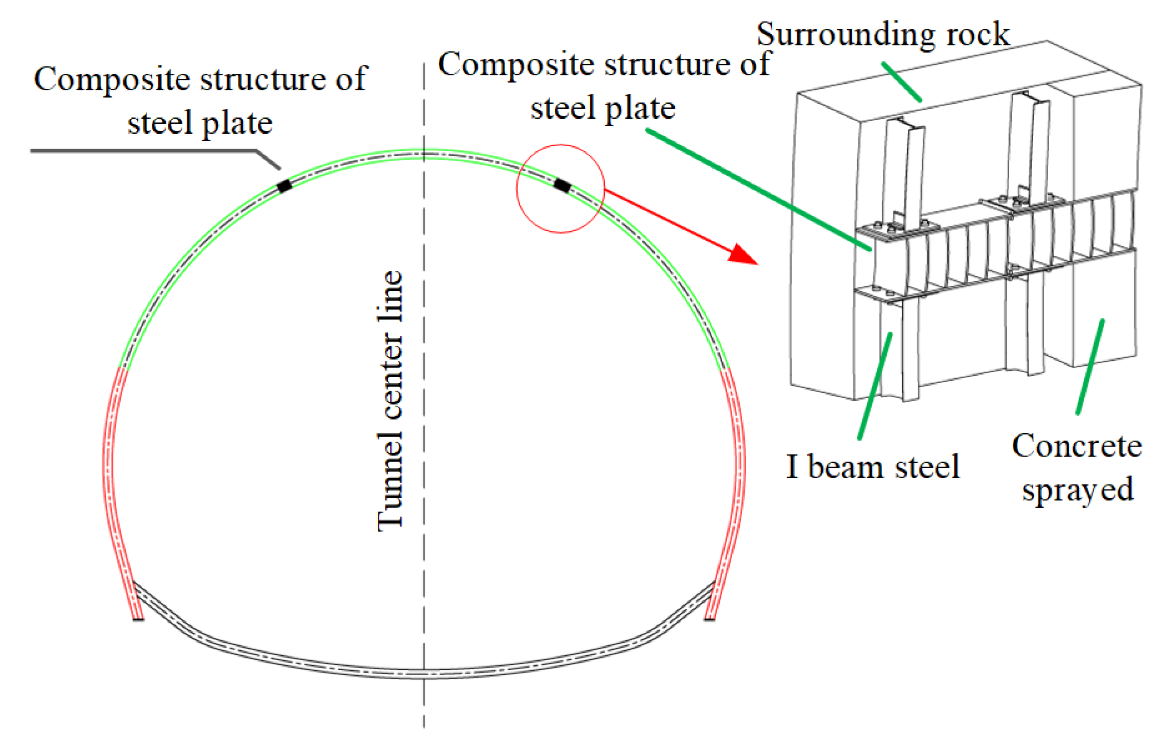
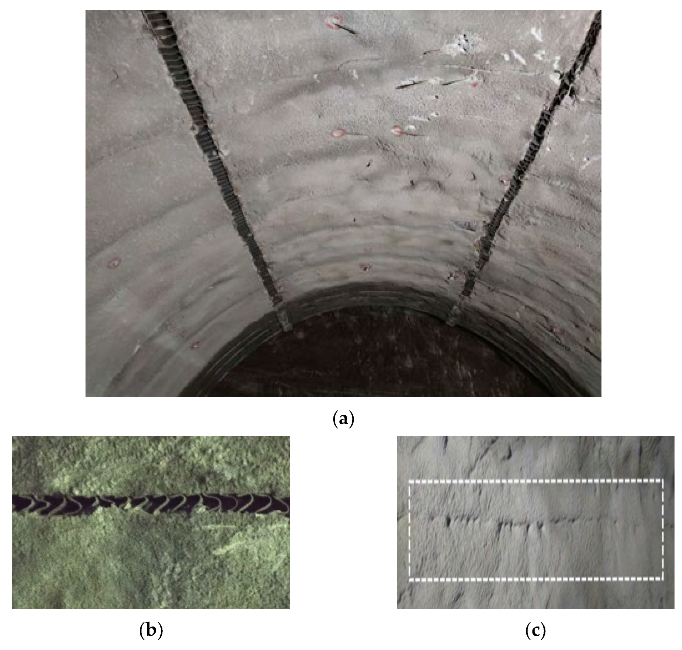
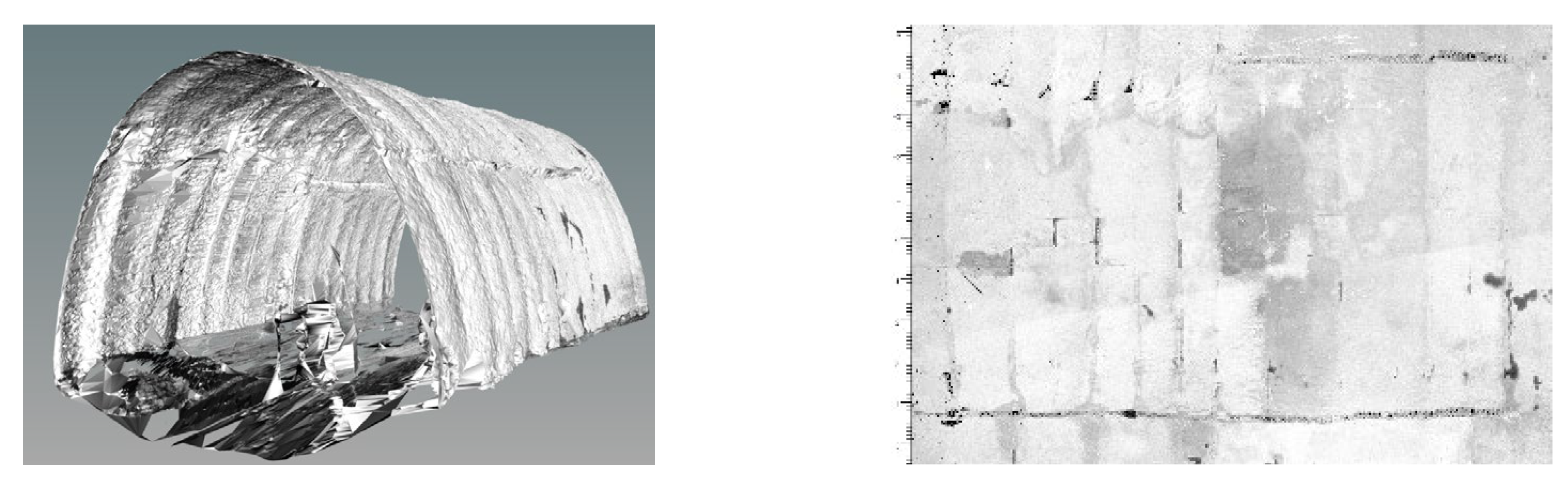
According to the 3D laser scanning monitoring results, the top and bottom steel plates of the steel plate composite structure have a thickness of 1 cm, and the height of the vertical plate is 28 cm with a thickness of 8 mm. The ring structure was installed at the initial support arch waist position to form a pressure support. The on-site monitoring results showed that (a) there was no cracking of the support structure and no concrete block falling; (b) the maximum stress of the sprayed concrete was 21.01 MPa and the maximum stress of the steel frame was 209.48 MPa, which were less than the design strength, which indicated that the support structure had a high safety coefficient; and (c) there were no safety accidents, which demonstrated that, in ensuring the safety of the construction site, the problem of initial support failure of tunnels in soft and weak surrounding rocks.

Author Contributions

Conceptualization, W.W. and W.Q.; methodology, W.Q.; validation, W.W. and W.Q; resources, W.Q.; data curation, W.W.; writing—original draft preparation, W.W.; writing—review and editing, W.W. and W.Q.; visualization, W.W.; supervision, W.Q.; project administration, W.Q.; funding acquisition, W.Q. All authors have read and agreed to the published version of the manuscript.

Funding

This research received no external funding.

Informed Consent Statement

Written informed consent has been obtained from the patient(s) to publish this paper.

Data Availability Statement

The sources of all data used in this study are presented in this manuscript.

Conflicts of Interest

The authors declare no conflict of interest.

References

  1. Hong, K.R.; Feng, H. Development and Thinking of Tunnels and Underground Engineering in China in Recent 2 Years(From 2019 to 2020). Tunn. Constr. 2021, 41, 1259–1280. [Google Scholar] [CrossRef]
  2. Qiu, W.G.; Wang, G.; Gong, L.; Shen, Z.; Li, C.; Dang, J. Research and application of resistance-limiting and energy-dissipating support in large deformation tunnel. Chin. J. Rock Mech. Eng. 2018, 37, 1785–1795. [Google Scholar] [CrossRef]
  3. Yan-Zong, L.I.; Pan, G.A.O.; Chong, J.U.; Wen-Xin, Z.H. Deformation Analysis and Primary Support Parameter Optimization: Case Study on Muzhailing Tunnel. Tunn. Constr. 2011, 31, 320–324. [Google Scholar]
  4. Cook, N.G.W. The basic mechanics of rockbursts. J. South. Afr. Inst. Min. Metall. 1963, 64, 71–81. [Google Scholar]
  5. Salamon, M.D.G. Energy considerations in rock mechanics: Fundamental results. J. South. Afr. Inst. Min. Metall. 1984, 84, 233–246. [Google Scholar] [CrossRef]
  6. Walsh, J.B. Energy changes due to mining. Int. J. Rock Mech. Min. Sci. Geomech. Abstr. 1977, 14, 25–33. [Google Scholar] [CrossRef]
  7. Lai, Y.; Cui, L. Introduction to Energy Support; Shanxi Coal: Taiyuan, China, 1994; Volume 5, pp. 18–23. [Google Scholar]
  8. Kovári, K.; Status, J. Basic considerations on tunnelling in squeezing ground. Rock Mech. Rock Eng. 1996, 29, 203–210. [Google Scholar] [CrossRef]
  9. Cantieni, L.; Anagnostou, G. The interaction between yielding supports and squeezing ground. Tunn. Undergr. Space Technol. 2009, 24, 309–322. [Google Scholar] [CrossRef]
  10. Zhou, H.; Xie, H.; Zuo, J. Developments in researches on mechanical behaviors of rocks under the condition of high ground pressure in the depths. Adv. Mech. 2005, 35, 91–99. [Google Scholar] [CrossRef]
  11. Heise, F.; Herbst, F. Lehrbuch der Bergbaukunde mit Besonderer Berücksichtigung des Steinkohlenbergbaues; Springer: Berlin/Heidelberg, Germany, 1923. [Google Scholar] [CrossRef]
  12. Schaechterle, K. Tunnelumbau in quellendem Gebirge. Die Bautech. 1926, 4, 437–440. [Google Scholar]
  13. Wu, K.; Shao, Z. Study on the effect of flexible layer on support structures of tunnel excavated in viscoelastic rocks. J. Eng. Mech. 2019, 145, 04019077. [Google Scholar] [CrossRef]
  14. He, M.; Gong, W.; Wang, J.; Qi, P.; Tao, Z.; Du, S.; Peng, Y. Development of a novel energy-absorbing bolt with extraordinarily large elongation and constant resistance. Int. J. Rock Mech. Min. Sci. 2014, 67, 29–42. [Google Scholar] [CrossRef]
  15. Brunar, G.; Powondra, F. Nachgiebiger Tübbingausbau mit Meypo-Stauchelementen. Felsbau 1985, 3, 225–229. [Google Scholar]
  16. Song, C.Y.; Li, C.; Zheng, Y.C.; Wang, H.C.; Wang, G.; Qiu, W.G. Comparative analysis for structure performance of two buffer layers in composite lining. Railw. Eng. 2021, 9, 63–67. [Google Scholar]
  17. Qiu, W.; Huang, H.; Yan, F.; Jiang, Y. A disaster with water inrush based on energy theorem in tunnels under saturated sandy stratum. Hazard Control Tunn. Undergr. Eng. 2021, 3, 11. (In Chinese) [Google Scholar]
  18. Tian, Y.; Chen, W.Z.; Tian, H.M.; Yang, J.P.; Zhang, Z.Y.; Shu, X.Y. Analytical model of layered rock considering its time-dependent behaviour. Rock Mech. Rock Eng. 2021, 54, 5937–5944. [Google Scholar] [CrossRef]
  19. Li, C.; Wang, G.; Qiu, W.; Gong, L.; Zhao, Y.; Wang, Q. Research and Application of Support Resistant Limiting Dampers in the Tunnel with High Horizontal Geostress. Mod. Tunn. Technol. 2021, 42, 88–97. [Google Scholar]
  20. Wang, G.; Gong, L.; Shen, Z.; Shuguang, L. Resistance-Limiting and Energy-Dissipating Support for Deep Buried Old Loess Tunnel. China Railw. Sci. 2021, 42, 88–97. [Google Scholar] [CrossRef]
  21. Liu, G.; Zhang, F.Y.; Li, X.Z.; Yang, Z.C. Research on large deformation and its mechanism of Muzhailing tunnel. Yanshilixue Yu Gongcheng Xuebao/Chin. J. Rock Mech. Eng. 2005, 24, 5521–5526. (In Chinese) [Google Scholar]
  22. Luo, J.; Wang, G.; Bai, Z.; Deng, Y. Application of Support Resistant Limiting Damper in Soft Rock Tunnel with Large Deformation in Expressway—A Case Study about Qiyun Tunnel of Yuchu Expressway Online First. Tunn. Constr. 2022, 43, 856–864. (In Chinese) [Google Scholar]
  23. Chen, J.L.; Shu, W.Y.; Li, J.W. Experimental Study on Dynamic Mechanical Property of Q235 Steel at Different Strain Rates. J. Tongji Univ. Nat. Sci. 2016, 44, 5. [Google Scholar]
  24. Dai, J.; Yang, X.; Wang, J.; Qiu, W.; Zhu, Q. Application of support resistant limiting damper in large-section double-track railway tunnel. Hazard Control Tunn. Undergr. Eng. 2022, 4, 44–51. (In Chinese) [Google Scholar]
  25. Versaillot, P.D.; Wu, Y.F.; Zhao, Z.L. Experimental study on the evolution of necking zones of metallic materials. Int. J. Mech. Sci. 2021, 189, 106002. [Google Scholar] [CrossRef]
  26. He, M.; Lu, X.; JIing, H. Characters of surrounding rockmass in deep engineering and its non-linear dynamic-mechanical design concept. J. Rock Mech. Eng. 2002, 8, 1215–1224. [Google Scholar] [CrossRef]
  27. Cheng, Y.-J.; Qiu, W.; Lei, J. Automatic extraction of tunnel lining cross-sections from terrestrial laser scanning point clouds. Sensors 2016, 16, 1648. [Google Scholar] [CrossRef] [PubMed]
Figure 1. Hazards of large-scale deformation: (a) buckling deformation of steel frame; (b) collapse during dismantling and replacement of steel frame.
Applsci 13 11972 g001
Figure 2. Respective characteristic curves of surrounding rock and support structure.
Applsci 13 11972 g002
Figure 3. The design concept of an energy-dissipation support.
Applsci 13 11972 g003
Figure 4. Principles of energy-dissipation support.
Applsci 13 11972 g004
Figure 5. Composite structure of a steel plate.
Applsci 13 11972 g005
Figure 6. Schematic diagram of the loading device: (a) Picture of the instrument; (b) Picture of the loading process
Applsci 13 11972 g006
Figure 7. The deformation process of the steel plate composite structure.
Applsci 13 11972 g007
Figure 8. Finite element analysis model.
Applsci 13 11972 g008
Figure 9. Deformation process of the computational model: (a) initial phase; (b) deformation phase; (c) compaction phase.
Applsci 13 11972 g009
Figure 10. Stress–deformation curve of the steel plate composite structure.
Applsci 13 11972 g010
Figure 11. Study area.
Applsci 13 11972 g011
Figure 12. Damage to the strengthening support implemented in the tunnel: (a) photographs of reinforcement support damage on site; (b) cloud image of 3D laser scanning.
Applsci 13 11972 g012
Figure 13. The deformation data of the original support.
Applsci 13 11972 g013
Figure 14. The design scheme of an energy-dissipation support.
Applsci 13 11972 g014
Figure 15. State of the energy-dissipation support: (a) status of work; (b) deformation of the structure; (c) shotcrete closure.
Applsci 13 11972 g015
Figure 16. Grayscale image of the tunnel.
Applsci 13 11972 g016
Figure 17. Deformation of key points.
Applsci 13 11972 g017
Figure 18. Pictures of field instrumentation: (a) installation of concrete strain gages; (b) installation of steel frame strain gages.
Applsci 13 11972 g018
Figure 19. Diagram of support stress: (a) concrete stress envelope diagram (unit: MPa); (b) stress envelope diagram of steel frame (unit: MPa).
Applsci 13 11972 g019aApplsci 13 11972 g019b
Table 1. Table of calculation parameters.
Steel Plate Composite StructureElastic ParameterPlastic Parameter
Elastic Modulus
E (Gpa)
Poisson’s Ratio
v
Yield Stress
σ p (MPa)
Plastic Strain
ε p
Upper and lower connecting plates200 × 1030.3
Vertical plate2000.33200
6500.12
Table 2. Simulated working conditions of the vertical steel plate.
Calculated Working ConditionsHeight of Vertical Plate (mm)Thickness of Vertical Plate (mm)
XZQ-12004
XZQ-22006
XZQ-32008
XZQ-42208
XZQ-52808
Table 3. Numerical simulation and compression test results statistics.
TypologyHeight (mm)Thickness (mm)Initial Peak Value (MPa)Constant Resistance Value (MPa)Compression RatioAccuracy
numerical simulation280815.31.779.6%95%
Indoor test280814.81.677.6%
Disclaimer/Publisher’s Note: The statements, opinions and data contained in all publications are solely those of the individual author(s) and contributor(s) and not of MDPI and/or the editor(s). MDPI and/or the editor(s) disclaim responsibility for any injury to people or property resulting from any ideas, methods, instructions or products referred to in the content.

