Article

Behavioral Investigations of Three Parallel Large Reinforced Concrete Circular Pipes with the Construction of Pipe Jacking

1
China Construction Eighth Engineering Division Co., Ltd., Shanghai 200135, China
2
School of Civil Engineering, Nanjing Forestry University, Nanjing 210037, China
*
Author to whom correspondence should be addressed.
Appl. Sci. 2023, 13(15), 8901; https://doi.org/10.3390/app13158901
Submission received: 11 June 2023 / Revised: 20 July 2023 / Accepted: 25 July 2023 / Published: 2 August 2023
(This article belongs to the Special Issue Tunneling and Underground Engineering: From Theories to Practices)

Abstract

:
The pipe jacking method is gradually attracting increasing levels of attention and is becoming an important method for constructing underground engineering. However, jacking large-size concrete pipes in urban core areas subjected to complicated geological conditions is still a big problem preventing the employment of the pipe jacking method, and further studies related to pipe jacking are required. This paper presents a case study on the construction of three parallel large-size reinforced concrete circular pipes in the upper-soft and lower-hard composite formations, in which the construction work was implemented using the slurry balance pipe jacking method with the sequence of jacking the 1# and 3# pipes prior to the 2# pipe being implemented in field construction. This case study was implemented by employing numerical simulations with the aforementioned pipe jacking sequence, which focused on the stress and deformation variations of the reinforced concrete circular pipes, as well as the vertical settlement of the ground surface during the jacking processes, and considering the influences from the excavation pressure and grouting pressure of the drag-reducing thixotropic slurry. The simulation results revealed that a higher excavation pressure from the pipe jacking machine can easily induce an excessive pushing and squeezing effect of the excavated soil with the uplift phenomenon, while the increasing grouting pressure can be used to reduce the overall vertical settlement of the ground surface, whereas an excessive grouting pressure may have no effectiveness on protecting the reinforced concrete circular pipes. This work provides the numerical foundations for investigating the behavior of jacked parallel large-size reinforced concrete circular pipes.

1. Introduction

Since its application in the Northern Pacific Road laying project in the United States, the pipe jacking method is gradually attracting elevated levels of attention and is becoming an important method for constructing underground engineering. With a developmental history of over 200 years, it is quite mature and has recently been successfully applied in the context of practical engineering, such as in tunnels, rainwater box culverts, and underground passages [1,2,3]. In view of previous studies, researchers have conducted many studies on the safety and efficiency of pipe jacking engineering. Ma et al. evaluated the distribution of land subsidence troughs through three-dimensional numerical simulations, in which the accumulated ground settlement linearly decreased with the increasing thickness of the jacked pipe within the range of 0.5 times the diameter of the jacked pipe, while the deviation of the peak value of the cumulative settlement tank gradually decreased as the horizontal clear distance between the jacked pipes increased [4]. Sagaseta proposed a displacement model to analyze the deformation caused by attitude control and soil loss [5]. Ren et al. proposed a ground deformation prediction method with a good predictive effect that considered multiple factors, such as positive additional thrust, friction, grouting pressure, and soil loss, in which the Mindlin solution was used to calculate the extent of ground deformation caused by the additional thrust and friction force on the front of the pipe jacking machine; the shear disturbance coefficient was used to calculate the effect of shear action on slowing down ground deformation, the Verruijt analytical solution was used to calculate the influence of the grouting pressure, while the Sagaseta method was used to calculate the extent of soil loss caused by over excavation [6]. Rowe et al. examined the soil settlement pattern influenced by tunnel construction by establishing a two-dimensional finite element model and improving their corresponding numerical simulation programs, which was expected to obtain the effects of variables including the soil elastic modulus, the soil static pressure coefficient, the pipe burial depth, grouting pressure, and soil anisotropy on deformation [7]. Wen et al. proposed five classical analytical calculation models and prediction formulae considering the pipe–soil–slurry interaction and introduced the three-dimensional finite difference method to estimate the jacking force [8,9]. Li et al. assessed the shear friction behavior and mechanical mechanisms between sandstone and concrete segments under seven different complex contact conditions, and established a three-dimensional finite element model based on the contact situation between the surrounding rock and the pipe segment during the rapid increase in the jacking force stage; the displacement control method was used to simulate the jacking process, and the comparison with the on-site monitoring results revealed that the numerical model can accurately predict the jacking force and verify the reliability of numerically calculated parameters [10]. Ye et al. established a calculation method for the jacking force that considers both lubrication and the pipe–soil–slurry interaction by introducing the effective friction coefficient, which reflects the contact state of the pipe soil slurry and the effect of the slurry drag on reducing frictional resistance [11].
However, there are still many problems and challenges restricting underground engineering construction using the pipe jacking method [12,13,14]. On the one hand, the cross-sectional size and cutting area of the pipe jacking machine are gradually increased to meet the increasing demand for underground pipelines, resulting in an increase in the range of soil disturbance and difficulties in controlling the ground settlement. On the other hand, the construction of multiple parallel pipelines is becoming more prevalent in pipe jacking engineering; the sequence of pipe jacking construction has a significant impact on the final settlement of the ground surface, and jacking the subsequent pipe also exhibits a major influence on the settlement and deformation of the previously jacked pipe. As a result, the deformation induced by pipe jacking needs to be controlled within a reasonable range to ensure the safety and usability of this method, and the soil settlement and mutual disturbance between pipes should be effectively reduced during the pipe jacking process. Notably, the practical projects of jacking large-size concrete pipes in urban core areas subjected to complicated geological conditions are becoming more prevalent in pipe jacking engineering, and the reasonable technical parameters and sequences for pipe jacking, as well as the appropriate auxiliary reinforcement measures, should be further studied.
In this paper, numerical investigations into the behavior of reinforced concrete circular pipes during the pipe jacking process were implemented, considering the influences of the excavation pressure and grouting pressure from the drag-reducing thixotropic slurry, in which the 1# and 3# pipes are jacked prior to the 2# pipe. This study focused on the variation in distribution of stress and deformation of the jacked reinforced concrete circular pipes, as well as the variation in vertical settlement of the ground surface during the pipe jacking process, and was expected to provide beneficial references for the further application and promotion of the pipe jacking method used for jacking parallel large-size reinforced concrete circular pipes across urban core areas.

2. Engineering Profile

The pipe jacking engineering in the Nanjing Yanziji comprehensive pipe gallery project has three parallel reinforced concrete circular pipes, as shown in Figure 1, which were constructed using the slurry balance pipe jacking method. The three parallel reinforced concrete circular pipes are labelled as the 1#, 2#, and 3# pipes, respectively, and are jacked through a protected area containing the Tuchengtou cultural relics, located underneath. All the pipes are jacked with a 100 m length. In the 1#, 2#, and 3# reinforced concrete circular pipes, the inner diameters are 4.5 m, 3.5 m, and 3 m, respectively, the corresponding outer diameters are 5.4 m, 4.2 m, and 3.6 m, respectively, and the relevant wall thicknesses are 0.45 m, 0.35 m, and 0.3 m, respectively, the spacings between the outer walls of the adjacent pipes are 4.2 m and 3.6 m, and the depth of the soil covering the reinforced concrete circular pipes ranges from 11.68 m to 15.08 m.
According to geological surveys, the pipe jacking engineering project mainly passes through silty clay and strongly weathered rock, as well as moderately weathered sandstone, with an upper-soft and lower-hard geological distribution. In terms of hydrology, the water mainly exists in bedrock fissures, the strongly weathered rock mass is extremely fragmented, the weathered fissures are relatively developed, the moderately weathered rocks also have weathered or structural fissures, but they are generally closed and have poor connectivity, which indicates that the overall water volume of bedrock fissures is not large, with poor water abundance and weak permeability, whereas the local bedrock fissures also contain a large amount of water during the rainy season. The pipe jacking machine passes through the whole section of silty clay and weathered rock.

3. Numerical Model for the Simulation of Jacking Reinforced Concrete Circular Pipes

The slurry-balanced pipe jacking machine was adopted to implement the pipe jacking engineering. The soil mass on the excavation surface is first cut by the rotating blade, and the soil and sand are transported to the slurry and water treatment system in the form of a slurry and water mixture through fluid transportation, and then the segments of reinforced concrete circular pipe are gradually pushed forward using the pipe jacking machine. The drag-reducing thixotropic slurry is then grouted around the reinforced concrete circular pipe, and the construction of the entire reinforced concrete circular pipe is completed. In the numerical analysis, the above practical processes of implementing the pipe jacking method are simulated, with the following imposed forces included in the numerical model: the grouting pressures and frictional resistance forces, excavation pressure on the tunnel excavation face, and the pushing pressure on the segment. Of these, the frictional resistance forces and excavation pressure, as well as pushing pressure, are related to the jacking forces from the pipe jacking machine [9,15,16].

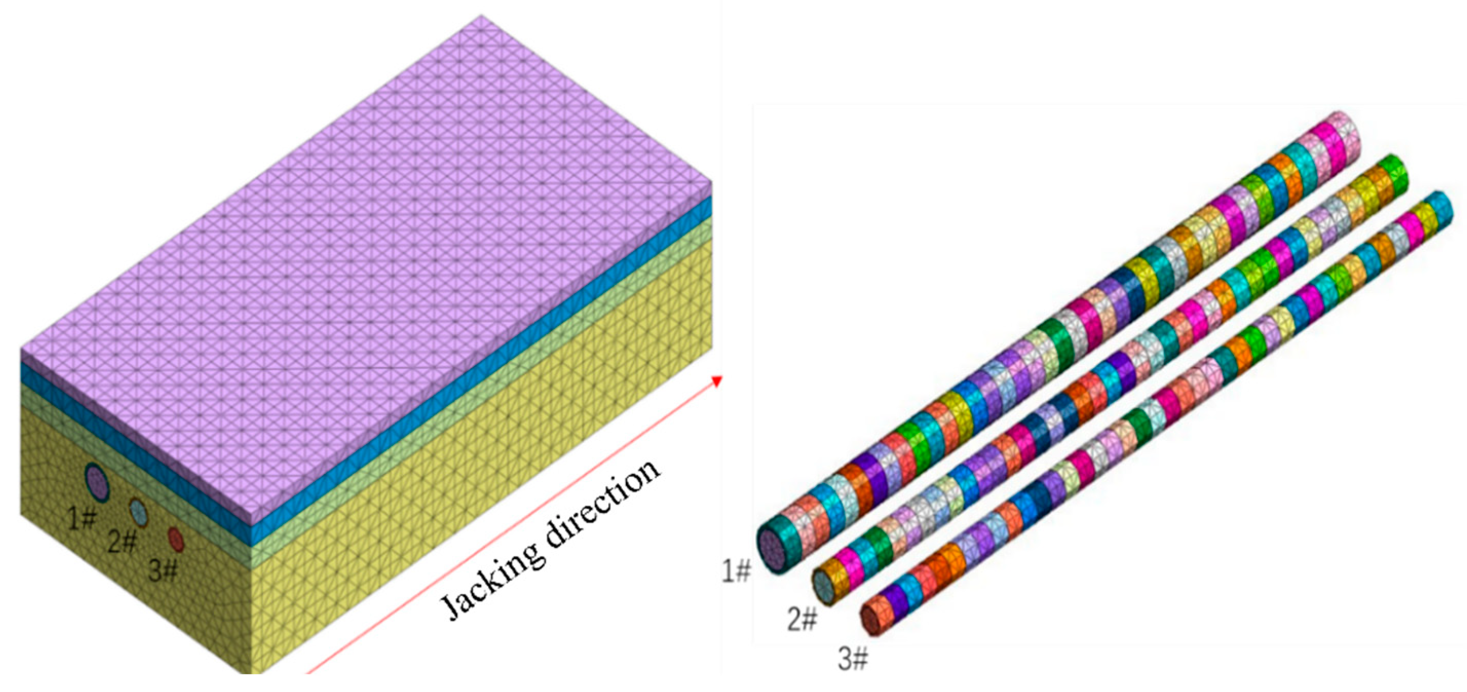
3.1. Geometric Model Establishment and Material Properties

The numerical model was based on the aforementioned pipe jacking engineering, which passes underneath the existing cultural relics. Figure 2 shows the numerical model of pipe jacking construction, in which the model size is nearly four times that of the soil mass around the pipe jacking engineering, which is 100 m long (y direction), 50 m wide (x direction), and 30 m high (z direction). Some assumptions of boundary conditions were adopted in the numerical model. The four lateral sides of the model were constrained horizontally, the bottom was constrained horizontally and vertically, and the upper boundary was a free boundary. In the numerical model, there were three reinforced concrete circular pipes with inner diameters of 4.5 m, 3.5 m, and 3 m, and the corresponding outer diameters of 5.4 m, 4.2 m, and 3.6 m, which were labelled as 1#, 2# and 3#, respectively. The jacking lengths of the three reinforced concrete circular pipes were all 100 m, the stand length of a single prefabricated reinforced concrete pipe section was 2.5 m, and the spacings between the outer walls of adjacent reinforced concrete circular pipes were 4.2 m and 3.6 m, respectively, which are the same as those in the field.
As demonstrated in Figure 2, the grid divisions of both the jacking pipes and soil mass were suitable to ensure the accuracy and running speed of the model calculation, and the tetrahedral grid was adopted for partitioning the numerical model. There were 17,041 nodes and 89,970 elements in the numerical model, and the 1.0 m size was used for the pipe gallery and 2.0 m size was employed in the soil mass.
The soil layer was divided into four layers according to the engineering survey, and the Mohr–Coulomb model was used to simulate the soil mass. The specific parameters of the material properties are shown in Table 1. The circumferential gap was generated between the soil mass and reinforced concrete circular pipe during the pipe jacking process, and the drag-reducing thixotropic slurry was injected around the reinforced concrete circular pipe to reduce the frictional resistance force thereafter. In the numerical model, the soil loss area after grouting the aforementioned drag-reducing thixotropic slurry was equivalently replaced by the reduced elastic modulus within a certain range of an equivalent layer with 20 mm thickness and set around the reinforced concrete circular pipe as demonstrated in Figure 3, in which the reduced elastic modulus of the equivalent layer with drag-reducing thixotropic slurry grouting was 2500 MPa, and the Poisson’s ratio and density of the equivalent layer with the drag-reducing thixotropic slurry grouting were 0.2 and 1200 kg/m3, respectively. Moreover, the concrete adopted in the reinforced concrete circular pipes had an elastic modulus of 34.5 GPa, a Poisson’s ratio of 0.3, and density of 2500 kg/m3.

3.2. Imposed Forces during Pipe Jacking

3.2.1. Excavation Pressure on Tunnel Excavation Face and Pushing Pressure on the Segments

Jacking force is also applied to the tunnel excavation face during jacking of the reinforced concrete pipes, in which a smaller excavation force causes the soil in front to collapse into the tunnel and induces the settlement of the upper soil mass, and a larger excavation force induces the uplift of the upper soil body. In the numerical simulation, the excavation pressure is applied to the excavated tunnel face using a uniformly distributed pressure load as shown in Figure 4, which covers the entire excavation soil area. The calculation of pipe jacking force is carried out using Equations (1) and (2), and the compressive stresses applied to the tunnel excavation face of the 1#, 2#, and 3# jacking pipes are 600 kPa, 750 kPa, and 600 kPa, respectively.
F p = π D 0 L f k + N F
N F = π 4 D g 2 γ s H s
where Fp is the calculated total jacking force (kN), D0 is the outside diameter of the reinforced concrete circular pipes (m), L is the designed jacking length (m), fk is the average frictional resistance force between the outer wall of the reinforced concrete circular pipes and the surrounding soil (kN/m2), NF is the drag force of pipe jacking machine (kN), Dg is the outside diameter of the pipe jacking machine (m), γs is the weight density of soil (kN/m3), and Hs is the covered depth of soil (m).
Moreover, the linear pushing pressure is applied to the segments of reinforced concrete circular pipe in the numerical simulation as demonstrated in Figure 4, which varies in real time according to the pushing situation of the reinforced concrete circular pipes, and the magnitudes of the pushing pressure are thus changed continuously with the increasing quantities of segments in the reinforced concrete circular pipes in the numerical simulation.

3.2.2. Grouting Pressures and Frictional Resistance Forces

Figure 5 shows the imposed loading modes of the grouting pressures and frictional resistance forces during the process of jacking the reinforced concrete circular pipes in the numerical simulation. The pressure from drag-reducing thixotropic slurry grouting was considered in the numerical model, since the process of grouting drag-reducing thixotropic slurry is implemented during the construction of pipe jacking, which immediately acts on the soil adjacent to the outer surface of the equivalent grouting layer and the outer surface of the reinforced concrete circular pipe with the direction normal to the outer surface of the pipe.
Moreover, the jacked reinforced concrete circular pipe is subjected to frictional resistance forces from the surrounding soil during the process of pipe jacking, in which the reinforced concrete circular pipe is more difficult to push with greater frictional resistance forces, and the drag-reducing thixotropic slurry is often injected around the reinforced concrete circular pipe to reduce the frictional resistance effect during the pipe jacking process. In order to simulate the effect of frictional resistance on the pipe jacking, a surface pressure loading with 2.5 kPa was applied to the interior of the equivalent layer with drag-reducing thixotropic slurry grouting as shown in Figure 5, in which the loading direction is opposite to the jacking direction of the pipe jacking machine.

4. Numerical Behavior of Jacking Reinforced Concrete Circular Pipes

4.1. Behavior Influenced by Excavation Pressure

4.1.1. Stress Distribution of the Jacked Reinforced Concrete Circular Pipes

Figure 6 shows the stress distributions of the jacked reinforced concrete circular pipes subject to different excavation pressures of 400 kPa, 600 kPa, and 800 kPa, in which the 1# and 3# pipes are jacked prior to the 2# pipe. It can be clearly seen that the change in excavation pressure has a relatively small impact on the stress of the reinforced concrete circular pipes. The maximum compressive stresses on the upper and lower parts of the 1# reinforced concrete circular pipe are 0.743 MPa and 1.768 MPa in the case with 400 kPa excavation pressure, and there are no significant changes in the stresses on the reinforced concrete circular pipe with increasing excavation pressure, which indicates that changing the excavation pressure does not have a substantial impact on the stress distribution of the reinforced concrete circular pipe. Moreover, the distributed stresses of the 2# reinforced concrete circular pipe are significantly larger than those of the 1# and 3# reinforced concrete circular pipes.

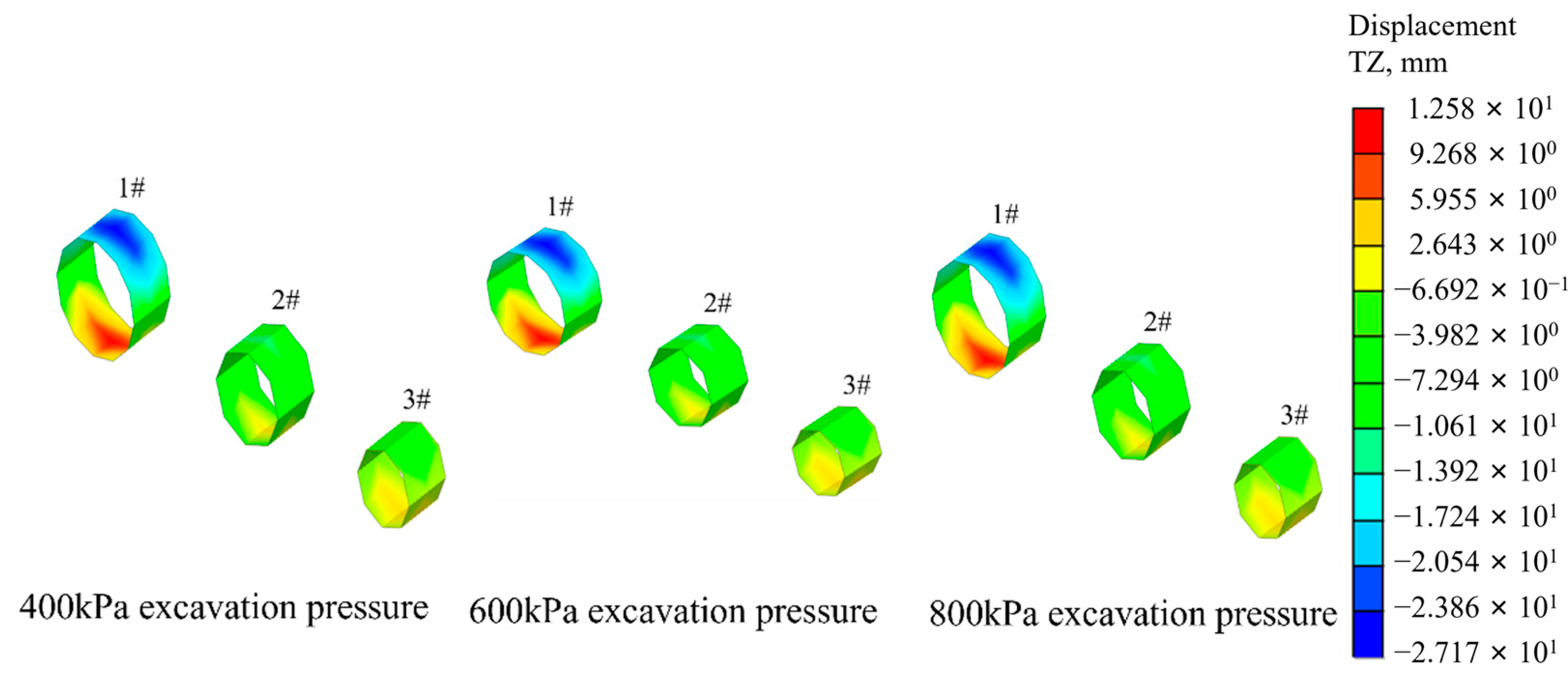
4.1.2. Deformation of the Jacked Reinforced Concrete Circular Pipes

Figure 7 shows the deformation of the jacked reinforced concrete circular pipes subject to the excavation pressures with 400 kPa, 600 kPa, and 800 kPa, in which the 1# and 3# pipes are jacked prior to the 2# pipe. The upper parts of all the three reinforced concrete circular pipes are subject to compressive stresses during the pipe jacking process, and the original circular shapes of all the three reinforced concrete pipes gradually develop elliptical shapes. The deformation of the upper part of the 1# reinforced concrete circular pipe was 26.8 mm at 400 kPa excavation pressure, and underwent has almost no change with increasing excavation pressure up to 600 kPa, before reaching 27.2 mm when the excavation pressure increased up to 800 kPa. Therefore, it can be seen that increasing the excavation pressure has little effect on the overall deformation of the jacked reinforced concrete circular pipes.

4.1.3. Vertical Settlements of Ground Surface

Figure 8 shows the vertical settlement of the ground surface with excavation pressures of 400 kPa, 600 kPa, and 800 kPa, when the 1# and 3# pipes were jacked prior to the 2# pipe. It can be clearly seen that the vertical settlement of the ground surface gradually decreased, whereas the size of reduction in the surface settlement is not significantly related to the increasing excavation pressure. The maximum vertical settlements were 8.89 mm, 8.67 mm, and 7.87 mm under 400 kPa, 600 kPa, and 800 kPa excavation pressures, and the overall vertical settlement of the ground surface shows a downward trend without any increase under the 400 kPa and 600 kPa excavation pressures. However, an increase was observed under the 800 kPa excavation pressure, which occurred on the ground surface more than 20 m away from the center of the excavation area. This also confirms that higher excavation pressure from the pipe jacking machine can easily induce excessive pushing and squeezing effect of the excavated soil with uplift phenomenon, in which the soil mass is continuously pushed outward and far away from the pipe jacking machine.

4.2. Behavior Influenced by Grouting Pressure from Drag-Reducing Thixotropic Slurry

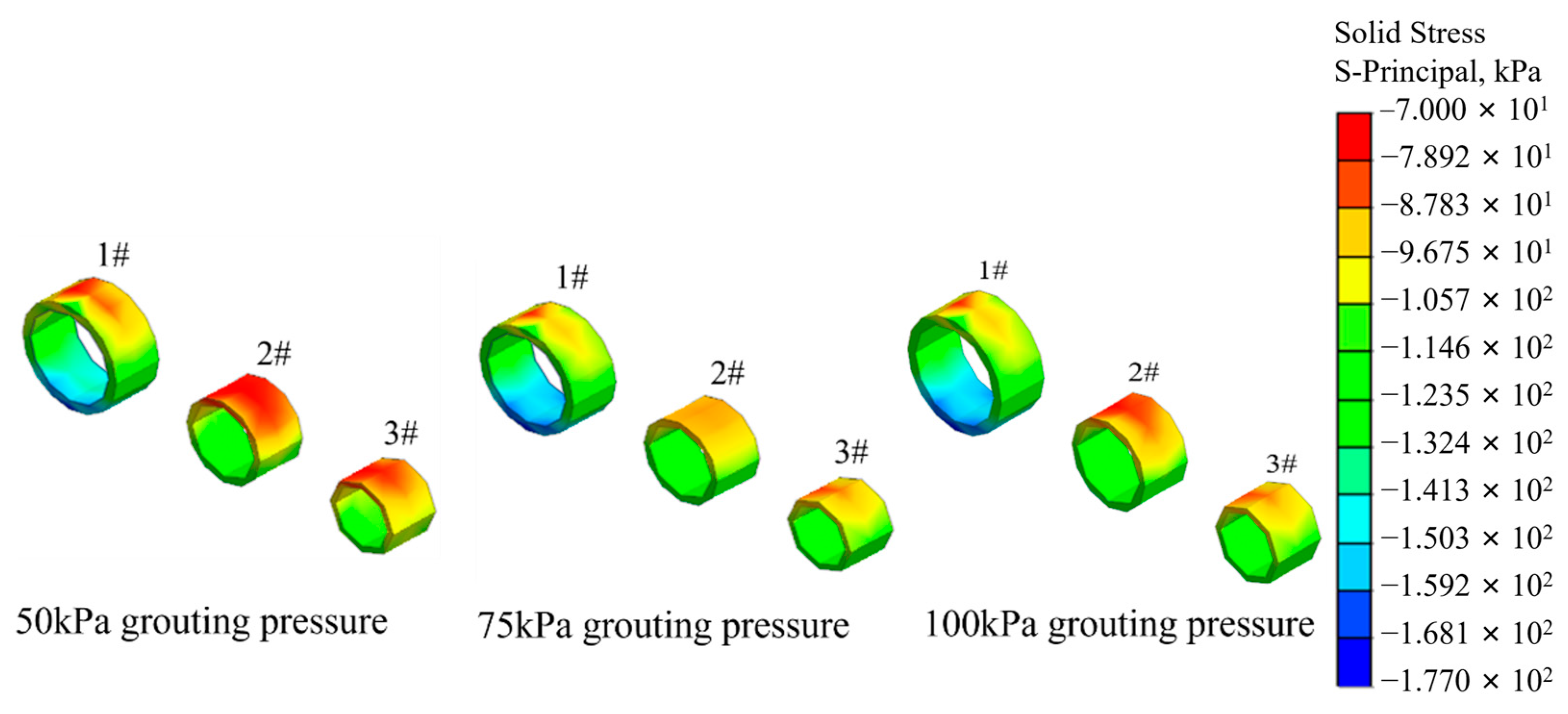
4.2.1. Stress Distribution of the Jacked Reinforced Concrete Circular Pipes

Figure 9 shows the stress distribution of the jacked reinforced concrete circular pipes with 50 kPa, 75 kPa, and 100 kPa grouting pressures from the drag-reducing thixotropic slurry, in which the 1# and 3# pipes were constructed prior to 2# pipe. It can be clearly seen that the 1# and 3# reinforced concrete circular pipes have the same stress distribution pattern, and all the reinforced concrete circular pipes show a situation in which both the upper and lower parts are subject to compressive stresses, which tend to develop from a circular shape to an elliptical shape due to the compressive stresses on the lower part being greater than those on the upper part. Moreover, the maximum compressive stresses on the upper and lower parts of the 1# reinforced concrete circular pipes were 0.73 MPa and 1.84 MPa, respectively, under 50 kPa grouting pressure, and were 0.64 MPa and 1.77 MPa, respectively, under 75 kPa grouting pressure. This indicates that increasing the grouting pressure can reduce the stresses on the reinforced concrete circular pipe, whereas the stress variation of the reinforced concrete circular pipe is not significantly related to the grouting pressure increasing to a certain extent. Therefore, the grouting pressure should be appropriately increased, but not too much, as excessive grouting pressure may have no effect on protecting the reinforced concrete circular pipes. Moreover, parts of the 1# and 3# reinforced concrete circular pipes adjacent to the 2# pipes are subject to a certain degree of compression caused by the jacking of the 2# pipes, in which the variations in stress of the reinforced concrete circular pipes are not significant. This confirms that the process of jacking the 2# pipe has a relatively small impact on the two sides of the jacked 1# and 3# reinforced concrete circular pipes.

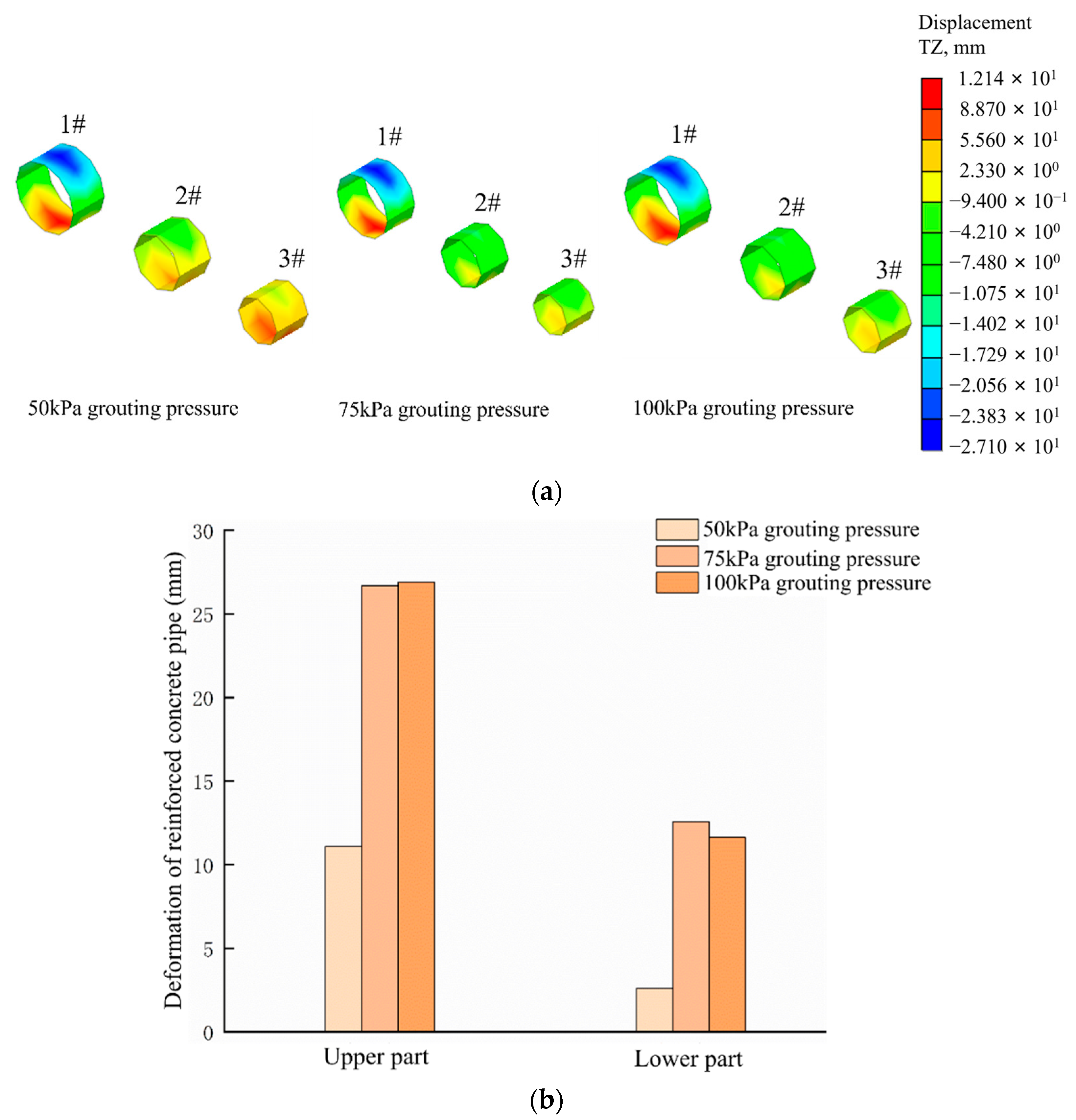
4.2.2. Deformation of the Jacked Reinforced Concrete Circular Pipes

Figure 10 demonstrates the deformation nephogram of the jacked 1#, 2#, and 3# reinforced concrete circular pipes, as well as the deformation histogram of the upper and lower parts of the 1# reinforced concrete pipe, in which the 1# and 3# pipes were jacked prior to the 2# pipe with 50 kPa, 75 kPa, and 100 kPa grouting pressure from the drag-reducing thixotropic slurry. It can be clearly seen that the main deformations occurred at the upper and lower parts of all the reinforced concrete circular pipes under the 50 kPa, 75 kPa, and 100 kPa grouting pressures, in which the maximum deformation at upper part of the 1# reinforced concrete circular pipe was 11.09 mm, 26.8 mm, and 26.93 mm, respectively, and at the lower part of the 1# reinforced concrete circular pipe was 2.62 mm, 12.5 mm, and 11.62 mm, respectively. This implies that the deformation of the reinforced concrete circular pipe significantly increased with increasing grouting pressure from 50 kPa to 75 kPa, whereas it varied little when grouting pressure increased from 75 kPa to 100 kPa, which indicates that the deformations at both upper and lower parts of the reinforced concrete circular pipes gradually increased as the grouting pressure increased, whereas they are changed little with increasing grouting pressure beyond a certain extent.

4.2.3. Vertical Settlements of Ground Surface

Figure 11 shows the vertical settlements of ground surface with 50 kPa, 75 kPa, and 100 kPa grouting pressure from the drag-reducing thixotropic slurry, in which the 1# and 3# pipes are jacked prior to the 2# pipe. It can be seen that the settlement curve of the ground surface has its center of settlement groove near the 1# reinforced concrete circular pipe, which shows a V-shaped trend and conforms to the settlement law with a Peck curve. The vertical settlement of the ground surface is 9.21 mm after jacking the 1# and 3# reinforced concrete circular pipes, and the ultimate vertical settlement of the ground surface is 9.87 mm after complete the jacking work of all the three pipes. This implies that the subsequent process of jacking the 2# pipe has little influence on the ultimate vertical settlement of the ground surface, which is dominantly influenced by jacking the 1# and 3# reinforced concrete circular pipes. Moreover, the final vertical settlements of ground surface were 16.6 mm, 16.47 mm, and 9.87 mm under 50 kPa, 75 kPa, and 100 kPa grouting pressures, respectively, which means the vertical settlement of the ground surface continues to decrease as the grouting pressure gradually increases, and increasing the grouting pressure can be used to reduce the overall vertical settlement of the ground surface.

5. Conclusions

In this paper, an investigation into the behavior of jacking reinforced concrete circular pipes was implemented by employing numerical analysis. A field construction sequence in which the jacking of the 1# and 3# pipes prior to the 2# pipe was considered in the numerical simulation, and the following conclusions can be drawn.
(1)
Increasing excavation pressure from the pipe jacking machine has little impact on the stress and overall deformation of the reinforced concrete circular pipe, whereas higher excavation pressure from the pipe jacking machine can easily induce an excessive pushing and squeezing effect of the excavated soil with uplift phenomenon, in which the soil mass is continuously pushed outward and far away from the pipe jacking machine.
(2)
Increasing grouting pressure can reduce the stresses of the reinforced concrete circular pipe, whereas the stress variation of the reinforced concrete circular pipe is not significantly related to the increasing grouting pressure to a certain extent, which means excessive grouting pressure may have no effect on protecting the reinforced concrete circular pipes, and an appropriate grouting pressure should be adopted during the pipe jacking process.
(3)
Firstly, jacking the 1# and 3# reinforced concrete circular pipes has an obvious influence on the ultimate vertical settlement of the ground surface and the stress distribution of the 2# reinforced concrete circular pipe, and the subsequent process of jacking the 2# reinforced concrete circular pipe has a relatively small impact on the ultimate vertical settlement of the ground surface and stress distribution of the jacked 1# and 3# pipes.
(4)
The main grouting-pressure-induced deformations occurred at the upper and lower parts of all the reinforced concrete circular pipes, and gradually increased with increasing grouting pressure, whereas they changed little after the grouting pressure had increased to a certain extent. Moreover, increasing grouting pressure can be used to reduce the overall vertical settlement of the ground surface due to continuously decreased vertical settlement of the ground surface with gradually increased grouting pressure.

Author Contributions

Conceptualization, M.M., L.H., Y.W., Q.L. and Y.Z.; validation, Y.Z.; investigation, M.M., L.H., Y.W. and Y.Z.; data curation, Q.L.; writing—original draft preparation, M.M., L.H. and Y.W.; writing—review and editing, Y.Z.; supervision, Y.Z.; funding acquisition, Y.Z. All authors have read and agreed to the published version of the manuscript.

Funding

This research was funded by Natural Science Foundation of Jiangsu Province (No. BK20211281).

Institutional Review Board Statement

Not applicable.

Informed Consent Statement

Not applicable.

Data Availability Statement

The data used to support the findings of this study are available from the corresponding author upon request.

Conflicts of Interest

The authors declare no conflict of interest.

References

  1. Sheil, B.B.; Suryasentana, S.K.; Templeman, J.O.; Phillips, B.M.; Cheng, W.C.; Zhang, L.M. Prediction of pipe-jacking forces using a bayesian updating approach. J. Geotech. Geoenviron. 2022, 148, 04021173. [Google Scholar] [CrossRef]
  2. Tao, L.J.; Zhang, Y.; Zhao, X.; Bian, J.; Chen, X.H.; An, S.; Han, X.C. Group effect of pipe jacking in silty sand. J. Geotech. Geoenviron. 2021, 147, 05021012. [Google Scholar] [CrossRef]
  3. Zhang, P.; Feng, X.; Zeng, C.; Ariaratnam, S.T. Field performance of steel pipes during curve jacking in Gongbei tunnel. Tunn. Undergr. Space Technol. 2022, 128, 104585. [Google Scholar] [CrossRef]
  4. Ma, W.J.; Wang, B.L.; Wang, X.; Zhou, S.H.; Wang, B.L. Soil layer disturbance caused by pipe jacking: Measurement and simulation of a case study. KSCE J. Civ. Eng. 2021, 25, 1467–1478. [Google Scholar] [CrossRef]
  5. Sagaseta, C. Analysis of undrained soil deformation due to ground loss. Geotechnique 1987, 37, 301–320. [Google Scholar] [CrossRef]
  6. Ren, D.J.; Xu, Y.S.; Shen, J.S.; Arulrajaj, A. Prediction of ground deformation during pipe-jacking considering multiple factors. Appl. Sci. 2018, 8, 1051. [Google Scholar] [CrossRef] [Green Version]
  7. Rowe, R.K.; Kack, G.J.A. theoretical examination of the settlements induced by tunneling: Four case histories. Can. Geotech. J. 1983, 20, 299–314. [Google Scholar] [CrossRef]
  8. Wen, K.; Zeng, W.; Shimada, H.; Sasaoka, T.; Hamanaka, A. Numerical and theoretical study on the jacking force prediction of slurry pipe jacking traversing frozen ground. Tunn. Undergr. Space Technol. 2021, 115, 104076. [Google Scholar] [CrossRef]
  9. Wen, K.; Shimada, H.; Zeng, W.; Sasaoka, T.; Qian, D.Y. Frictional analysis of pipe-slurry-soil interaction and jacking force prediction of rectangular pipe jacking. Eur. J. Environ. Civ. Eng. 2020, 24, 814–832. [Google Scholar] [CrossRef]
  10. Li, C.; Zhong, Z.L.; Liu, X.R.; He, G.N. Numerical simulation for an estimation of the jacking force of ultra-long-distance pipe jacking with frictional property testing at the rock mass-pipe interface. Tunn. Undergr. Space Technol. 2019, 89, 205–221. [Google Scholar] [CrossRef]
  11. Ye, Y.C.; Peng, L.M.; Zhou, Y. Prediction of friction resistance for slurry pipe jacking. Appl. Sci. 2020, 10, 207–227. [Google Scholar] [CrossRef] [Green Version]
  12. Shen, S.L.; Cui, Q.L.; Ho, C.E.; Xu, Y.S. Ground response to multiple parallel microtunneling operations in cemented silty clay and sand. J. Geotech. Geoenviron. 2016, 142, 04016001. [Google Scholar] [CrossRef]
  13. Jiang, X.; Zhang, X.H.; Wang, S.; Bai, Y.; Huang, B.S. Case study of the largest concrete earth pressure balance pipe-jacking project in the world. Transport. Res. Rec. 2022, 2676, 92–105. [Google Scholar] [CrossRef]
  14. Zeng, C.; Xiao, A.F.; Liu, K.X.; Ai, H.; Chen, Z.H.; Zhang, P. Experimental study on the influence of slurry concentration and standing time on the friction characteristics of a steel pipe-soil interface. Appl. Sci. 2022, 12, 3576. [Google Scholar] [CrossRef]
  15. Yen, J.; Shou, K. Numerical simulation for the estimation the jacking force of pipe jacking. Tunn. Undergr. Space Technol. 2015, 49, 218–229. [Google Scholar] [CrossRef]
  16. Liu, J.M.; Cheng, H.; Cai, H.B.; Wang, X.S. Design and analysis of grouting pressure in slurry pipe jacking based on the surrounding soil stability mechanical characteristics. Geofluids 2022, 2022, 4697730. [Google Scholar] [CrossRef]
Figure 1. Section diagram of the reinforced concrete circular pipes in pipe jacking engineering.
Applsci 13 08901 g001
Figure 2. Numerical model of pipe jacking construction.
Applsci 13 08901 g002
Figure 3. Equivalent layer with drag-reducing thixotropic slurry grouting in the numerical model.
Applsci 13 08901 g003
Figure 4. Imposed mode of excavation pressure on tunnel excavation face and pushing pressure on segments of reinforced concrete circular pipe. (a) Tunnel excavation face. (b) Reinforced concrete circular pipe.
Applsci 13 08901 g004
Figure 5. Imposed loading modes of grouting pressures and frictional resistance forces. (a) Grouting pressures. (b) Frictional resistance forces.
Applsci 13 08901 g005
Figure 6. Stress distribution nephogram of the reinforced concrete circular pipes with 400 kPa, 600 kPa, and 800 kPa excavation pressures.
Applsci 13 08901 g006
Figure 7. Deformation nephogram of the reinforced concrete circular pipes with 400 kPa, 600 kPa and 800 kPa excavation pressures.
Applsci 13 08901 g007
Figure 8. Vertical settlement of ground surface with 400 kPa, 600 kPa, and 800 kPa excavation pressures.
Applsci 13 08901 g008
Figure 9. Stress distribution nephogram of the reinforced concrete circular pipes with 50 kPa, 75 kPa, and 100 kPa grouting pressures.
Applsci 13 08901 g009
Figure 10. Deformations of the reinforced concrete circular pipes with 50 kPa, 75 kPa, and 100 kPa grouting pressures. (a) Deformation nephogram of the 1#, 2#, and 3# reinforced concrete circular pipes; (b) Deformation histogram of upper and lower parts of the 1# reinforced concrete pipe.
Applsci 13 08901 g010
Figure 11. Vertical settlements of ground surface with 50 kPa, 75 kPa, and 100 kPa grouting pressures. (a) Vertical settlement of the ground surface with 100 kPa grouting pressure; (b) Histogram of vertical settlement of the ground surface.
Applsci 13 08901 g011
Table 1. Parameters of soil layers.
Soil LayerDepthDensityElastic ModulusPoisson’s RatioCohesive ForceFriction Angle
mkg/m3MPa kPa°
miscellaneous filled soil218504.50.15812
plain filling soil320004.50.3810
silty clay3.5190060.33330
strongly weathered sandstone21.52100200.262015
Disclaimer/Publisher’s Note: The statements, opinions and data contained in all publications are solely those of the individual author(s) and contributor(s) and not of MDPI and/or the editor(s). MDPI and/or the editor(s) disclaim responsibility for any injury to people or property resulting from any ideas, methods, instructions or products referred to in the content.

