Featured Application
Buildings.
Abstract
This research aims to investigate the impact of incorporating porous materials on reducing noise and vibration in wooden floor panels, and to analyze the vibroacoustic performance of the assembled panel under different types of excitation and boundary conditions, particularly in the lower frequency range. The study begins with an experimental investigation and numerical modeling to determine the mechanical properties of the orthotropic wood material used in the floor panels. Subsequently, a finite element formulation, based on a variational approach, is presented to study the vibroacoustic response of an elastic structure coupled with a porous material exhibiting realistic behavior. The porous material is characterized by two phases: solid and fluid, represented in the formulation through the displacement field for the solid phase and the pressure for the fluid phase. This formulation offers the advantage of reduced computation cost and simplifies the coupling between all domains. To calculate the acoustic radiation of the structure, the Rayleigh integral is employed. Utilizing the proposed numerical approach, a comprehensive study is conducted to analyze the reduction in vibration–acoustic response of the floor with the incorporated porous layer, taking into account different types of excitation and boundary conditions applied to the system.
1. Introduction
A timber floor panel is a construction element that is typically made up of a layer of timber or wood-based material, which is often supported by a framework of wooden joists or beams. Timber floor panels are commonly used in residential and commercial buildings as a structural and finishing element for floors, and they may also serve as a base for other types of flooring materials, such as carpet, tile, or hardwood. Acoustic and vibration design of timber floor panels is an important consideration in building design, and can have significant impacts on the comfort, safety, and sustainability of a building over its lifespan [1]. A timber floor panel with poor vibroacoustic properties can lead to high levels of noise and vibration transmission between floors, which can be disruptive and lead to a lack of privacy and productivity. It can also affect the structural integrity and durability of the timber floor panel over time, causing fatigue and damage to the timber. The introduction of damping materials is an important technique for reducing vibration and improving sound insulation in timber floor panels. Vibration caused by impact or walking can create noise and discomfort for building occupants. Damping materials, such as viscoelastic layers or porous materials [2], can absorb sound and vibration energy, which helps to dampen the panel’s natural frequencies and reduce its resonance. On the other hand, the connection between the timber floor panel and the supporting structure is another important factor in the vibroacoustic behavior of such a structure [3]. A rigid connection (boundary conditions) can help to distribute the load evenly across the panel and prevent it from vibrating excessively as it reduces the deflection of the panel [4,5]. In contrast, a weak or flexible connection can allow the panel to move more freely, which can increase the amount of vibration and sound transmission.
Eurocode 5 [6] specifies the serviceability limit states (SLS) for timber floors based on vibrational factors such as fundamental frequency, unit point load deflection, and unit impulse velocity response. Furthermore, the methods for calculating these characteristics are suggested in the National Annexes of the European nations, which vary greatly from one another due to differences in design approaches, manufacturing operations, and building techniques. The common suggestion is that the vibrational performance of the floor is controlled by assuring the fundamental natural frequency is greater than 8 Hz, and through limiting the deflection under the unit point load and the unit impulse velocity response. The vibration response of different types of floor systems (composite, concrete, steel with timber) was identified under the action of human activities [7,8,9,10,11]. Damping ratios were found to be in the range of 0.5% to 1.3% for any of the first five first-order principal modes. Bernard [12] investigated the effect of various structural modifications on the rigidity and dynamic response of timber flooring systems constructed with I-joists or laminated glued lumber (LGL) joists.
Nowadays, a lot of researchers have started to investigate the vibroacoustic of timber floor panels. Yang et al. [13] present an analysis of the vibroacoustic properties of cross-laminated timber (CLT) panels using wave and finite element (WFE) methods. The study compares two WFE modeling approaches to a commonly used orthotropic plate model. The research finds that the models are in good agreement at low frequencies but diverge at higher frequencies, where the vibroacoustic behavior of the panel becomes more complex. The paper concludes by comparing predicted results to experimental measurements and assessing the impact of uncertainty in different structural material properties on sound-transmission loss. Caniato et al. [14] discuss the results of in situ measurements conducted on full-scale timber constructions to analyze the frequency behavior of impact noise from bare floors and the influence of floating-floor technology on timber horizontal partitions. The research proposes a new frequency model for the impact noise of cross-laminated timber bare floors and compares wooden structures to traditional technologies. The influence of floating floors, mineral wool, and screwed ceilings is analyzed, with the suspended ceiling found to be the best way to reduce impact noise. Filippoupolitis et al. [15] describe the development and validation of finite element methods (FEM) for simulating the dynamic response of a dowelled-joist wood floor at low frequencies up to 200 Hz. The FEM models were validated against experimental modal analysis, and both rigid and spring connectors were used to model dowel connections between the joists. In their study, Conta and Homb [3] performed experimental investigations, to study the vibroacoustic behavior of long-span floor systems made of stiff floor elements with high-rotational-stiffness supports. Measurements were conducted using experimental modal analysis and the integral transform method was used to identify modal properties and sound radiation under impact excitation. The element size and boundary conditions significantly impacted radiated sound power at low frequencies, and sound radiation above 50 Hz can be efficiently reduced using traditional strategies such as gravel in the cavity of the floor elements. Proença et al. [16] investigate the acoustic performance of composite sandwich panels in building construction. Experimental and numerical tests are performed on a full-scale panel, confirming its overall low acoustic performance due to its light weight. The study highlights the need for additional sound-insulation measures and validates the application of the reciprocity theorem to accurately predict impact sound-pressure levels based on numerical results of airborne sound reduction. Granzotto et al. [17] studied the acoustic and vibrational behavior of a 200 mm cross-laminated timber (CLT) floor using noise sources such as a dodecahedron, standard tapping machine, and rubber ball. Sound pressure and velocity levels were measured, and a prediction law was derived. The study focuses on understanding the CLT floor’s performance and provides an analysis of the sound-radiation index. Based on a comprehensive literature review in this field, there have been limited numerical studies dedicated to the modeling of wood floors treated with porous materials within the low-frequency domain. In this frequency range, the boundary conditions affect the vibroacoustic characteristics of the system. The coupling between the wood structure and the porous material also has a major influence in this frequency range, necessitating the development of a model that takes into account both phases of the poroelastic medium, as well as wave propagation in the solid domain of the porous material. Biot’s displacement–pressure model, proposed and used in this study in timber floor panels (one of the original features of this research work), will enable us to understand this strong interaction and take account of the elastic behavior of its skeleton.
This paper presents a comprehensive investigation of the behavior of a timber floor panel, with a primary focus on addressing noise-radiation issues and enhancing vibration control in the low-frequency range. The study introduces a novel approach by exploring the use of a porous-material layer to achieve these goals. The paper is structured into three main sections. The first section provides a detailed description of the timber floor panel’s components, including beams, joists, and flooring. It also explores different connection types and presents damping ratio estimates for various timber floor types. To determine the mechanical properties of the glued laminated timber (glulam) beams, four-point bending tests are conducted. Furthermore, finite element models are developed to detect material parameters, ensuring accurate alignment with experimental force–displacement curves. Moving on, the second section focuses on the finite element formulation of sound radiation in the panel incorporating the porous-material layer. The porous material is characterized using Biot theory, with the solid-phase displacement and the fluid-phase pressure being key parameters. Predictions of radiated sound power and sound-transmission loss are made using the Rayleigh integral and variational formulations. In the last section, the paper implements the proposed finite element approach to analyze the timber floor panel’s vibroacoustic response. Different loading scenarios, including walking time history and washing machine time history, are considered. The fundamental frequencies of the panel and the effect of boundary conditions on resonance peaks are examined. The parametric study demonstrates the positive impact of the porous-material layer on noise reduction and vibration control.
2. General Structural Design
2.1. Floor Panel Description
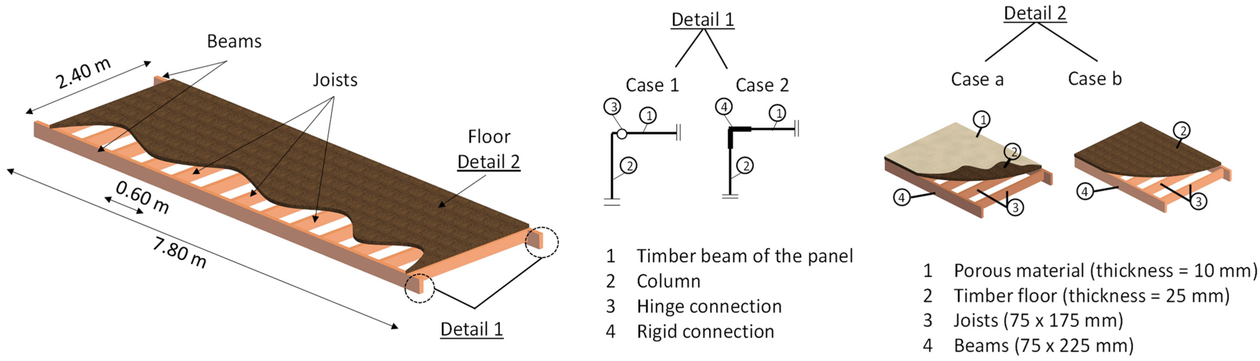
A timber floor panel consisting of glued laminated elements (beams, joins, and floor) is investigated in this study. The dimensions of the panel have been defined to ensure appropriate implementation and transport conditions so its width is fixed at 2.40 m, and its length at 7.8 m. Each panel consists of two main glulam beams (75 × 225 mm) in the longitudinal direction, thirteen glulam joists in the transversal direction (75 × 175 mm) with a spaceman of 0.60 m, and a 25 mm of timber floor that connects the beams (Figure 1). The beams of this panel are the parts that are connected with the vertical elements of the structure (columns, facades, etc.). In this study, the panel is investigated for two connection types (see detail 1 of Figure 1), as the connection’s stiffness can vary [4,18]. In addition, the case study examines the effects of the porous material on the floor of the panel in order to damp the vibroacoustic response of the structure (see detail 2 of Figure 1). The timber material of the main parts of this floor panels is categorized in the class GL24h, but experimental tests have been conducted by the authors of the present study (see Section 2.2).
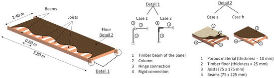
Figure 1.
Geometric configuration of the timber floor panel.
2.2. Experimental and Numerical Determination of the Mechanical Properties of Glued Laminated Timber
Glued laminated timber, commonly referred to as glulam, is a structural timber product made from glued smaller pieces of wood elements. Glued laminated timber can be produced in either a straight or curved form, with the grain of all laminations essentially parallel to the axis of the member. A supporting standard, Table 1 of BS EN 338:2009 [19], contains the material property values. Eurocode 5 [6] addresses the material properties and defines the strength and stiffness parameters, stress–strain relations, and provides values for modification factors for strength and deformation according to various service classes and/or load-duration classes, but it does not contain the material property values.

Table 1.
Main material parameters.
Four-point bending tests have been conducted until the failure of the beams (glulam GL24h, which consists of 4 layers) at 2.30 m long and a cross-section of 90 × 180 mm (Figure 2). Seven different sequences have been conducted and the envelope of the experimental curves is presented in Figure 3. During the experimental set up the deflection was measured using a linear variable differential transformer (LVDT), located on both two sides of the beam in the middle of the span (Figure 2). The total deflection was calculated as the mean value of both measurements, and the failure load was registered. These experimentally derived material properties were utilized in the subsequent numerical study.
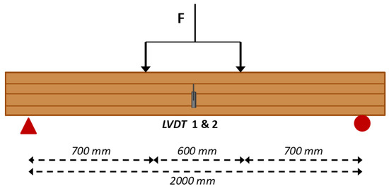
Figure 2.
Description of the four-point bending tests in a glulam beam of GL24h.
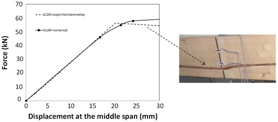
Figure 3.
Experimental and numerical force–displacement curve of GL24h beam.
Numerical models, using the finite elements method (FEM), were developed and the FEM model geometry reproduced the actual geometry of the experiments. In addition, the simulation used the same boundary conditions and loading as in the experimental program. The physical and mechanical properties, obtained from the previous experimental tests, were used as input data in the FEM model. The modulus of elasticity perpendicular to the grain () was estimated according to Equation (1) [20].
where is the modulus of elasticity parallel to the grain.
Elastoplastic orthotropic material models were used with non-linear hardening associated with material densification. The orthotropic material parameters were optimized to match the experimental force–displacement curves, while the densities were determined by weighing the specimen and measuring their dimensions. Table 1 summarizes the details of the material properties. is the Young’s modulus along axis 1 (axis 1 is the axis parallel to the wood grain), is the Young’s modulus along axis 2, and is the Young’s modulus along axis 3. The assumption that has been made in this study (axes 2 and 3 are the axes perpendicular to the wood grain). is the bending strength, is the Poisson ratio in the planes 12, 13, and 23, respectively, while is the characteristic density.
The comparison of the experimental results with the numerical ones in terms of force–displacement curves are illustrated in Figure 3. The difference between the experimental and the numerical results for displacements after the maximum bending strength is related to the structural adhesives between the layers of glued laminated timber and its failure mode (detachment of layers), which were not modeled in the present study. This work is focused on small floor displacements, in the elastic domain, so the outcomes are not affected.
In the numerical model, the damping value of wood, which has been proposed by the EN 1995-1-1, is used [6] (.
3. Finite Element Formulation of Sound Radiation of an Elastic Structure with a Poroelastic Layer
3.1. Local Equations
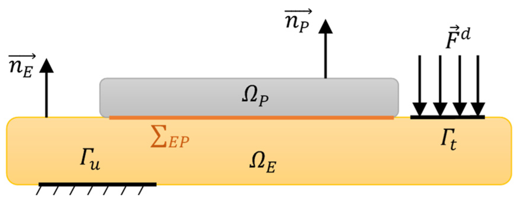
We consider an elastic structure occupying the domain , clamped on its boundary , and subject to external forces on its boundary (Figure 4). A poroelastic layer of domain is fixed to the elastic structure in order to dampen its sound radiation. The structure–poroelastic interface is denoted . , and represent the exterior normals of the structure and poroelastic domains, respectively. The effects of gravity are neglected.
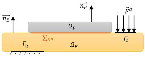
Figure 4.
Elastic structure coupled to poroelastic layer.
The porous material is modeled in this work using Biot theory [21]. This theory is applied when the porous material has an elastic matrix. In this case, the material is defined by its porosity , static flow resistance , tortuosity , viscous length , and thermal length . The elastic skeleton is characterized by its Young’s modulus , Poisson’s ratio , structural damping coefficient and its density . In total, the poroelastic material is characterized by nine parameters.
The local equations of the coupled elastic–poroelastic problem can be written in terms of the displacement of the elastic structure , the displacement of the solid phase of the porous , and the pressure for the fluid phase of the porous [22,23]:
- Elastic structure:
- Poroelastic material (solid phase):
- Poroelastic material (fluid phase):
The continuity conditions between the elastic-solid domain and the porous medium are expressed as [24,25]:
where is the displacement of the fluid phase of the porous material.
Equation (4a) ensures the continuity of displacement between the solid skeleton and the elastic structure. Equation (4b) expresses the fact that there is no relative-mass flux across the boundary . Finally, the continuity of the total normal stress between the elastic structure and the poroelastic material is expressed by Equation (4c).
3.2. Variational Formulation
The variational formulation of the problem is obtained from the local equations of the previous paragraph by applying the test function method. It is written for the different domains as follows [26,27]:
- Elastic structure:
- Poroelastic material (solid phase):
- Poroelastic material (fluid phase):
By summing the coupling terms defined at the structure–poroelastic interface in the integral Equations (5)–(7), we find the following expression:
Equation (8) shows that the porous material is coupled to the elastic domain through a symmetrical coupling term. For most of porous materials used in acoustic, the bulk modulus of the poroelastic material is negligible compared with the bulk modulus of the material from which the skeleton is made; thus, it is assumed the coefficient [25]. In this case, the integrals in Equation (8) become with the same form as the usual elastic structure–acoustic coupling condition. Thus, at the surface , the coupling is explicitly imposed with only the kinematic condition . We, therefore, deduce that the formulation for the porous material, other than the reduction of the numerical cost, has the advantage of the simplicity of coupling with other domains compared to the formulation, with the displacement of the two solid and fluid phases of the porous.
3.3. Finite Element Discretization
The resolution of the multiphysics problem considered in this work is conducted using the finite element method. Thus, introducing the vectors of nodal displacement of the elastic structure and the solid phase of the porous . As well as the vector of nodal pressure in the fluid phase of the poroelastic , the discretization of the bilinear forms of the previous variational formulation (Equations (5)–(7)) gives us the following coupled matrix system:
where and , and , and are the stiffness and mass matrices of the elastic structure, and the solid phase and the fluid phases of the porous material, respectively. is a poroelastic phases-coupling matrix. is the coupling matrix assuring that on . is the vector of nodal forces applied to the structure. The system (9) is solved by a direct approach in the frequency domain, and at each frequency step the frequency-dependent matrices of the porous medium are updated. It leads simultaneously to the nodal displacements of the elastic structure and the porous solid phase and the nodal pressures in the fluid porous phase. The size of the system can be partially reduced by projecting the variables of the elastic structure onto a truncated projection basis calculated from the elastic-structure modes of the problem. However, due to complex dissipation mechanisms and frequency dependence of the structural and acoustic properties of the porous material, the associated eigenvalue problem is non-linear and prevents the use of reduced projection bases for this domain.
3.4. Prediction of Radiated Sound Power
The acoustic indicators used in this work to evaluate the sound insulation of the studied structure are the radiated sound power and the sound-transmission loss . The Rayleigh integral can be used to calculate the pressure at any point in the external acoustic domain due to the vibration of an elastic-plane structure and radiating in a rigid baffle [28]. This integral equation requires knowledge of the normal velocity at any point G on the vibrating plate of surface . It can be written as Equation (10) [28,29,30,31]:
where is the volume density of the external acoustic domain; is the wave number (); is the speed of sound in the acoustic domain; and is the distance between and . The velocity distribution can be obtained through finite element simulation.
Therefore, the radiated power is given by
where is the complex conjugate of the normal velocity and is the real part of the expression.
The baffled panel is divided into a grid of R rectangular elements with equal size whose transverse vibrations are specified in terms of the normal velocities at their center positions. Assuming that the dimensions of the element are small compared with both the structural wavelength and the acoustic wavelength, the total radiated sound power (Equation (11)) can then be expressed as the summation of the powers radiated by each element, so that
where the exponent denotes the Hermitian transposition; and are the vectors of the complex amplitudes of the normal velocity and the acoustic pressure in all elements; and is the area of each element. The pressure on each element is generated by the vibration of all elements in the plane. The vector of the acoustic pressure can, therefore, be expressed by the impedance matrix relation
where is the matrix incorporating the point and transfer acoustic-impedance terms over the grid of elements into which the panel has been subdivided:
and where is the distance between the centers of the ith and jth elements. Note that, because of reciprocity, the impedance matrix is symmetric. Substituting Equation (13) into the expression for the total radiated sound power given in Equation (12), we obtain
The matrix is defined as the “radiation resistance matrix” for the elementary radiators which, for the baffled panel [30,31], is given by
The normal incidence sound transmission of the double-wall sandwich panels is evaluated using the following formula:
where is the incident acoustic power.
4. Dynamic Analyses and Parametric Study
The finite element formulation presented in this article is implemented in Matlab and will be utilized to investigate the vibroacoustic response of the system. For modeling the wooden panel (joists, beams and wooden floor), 8-node solid elements are employed, resulting in a mesh with 16,608 elements. The porous layer is modeled using voluminal elements of the hexahedral type, featuring 8 nodes per element, and a total of 824 elements. A compatible mesh is ensured at the interface between the panel and the porous layer.
4.1. Loading
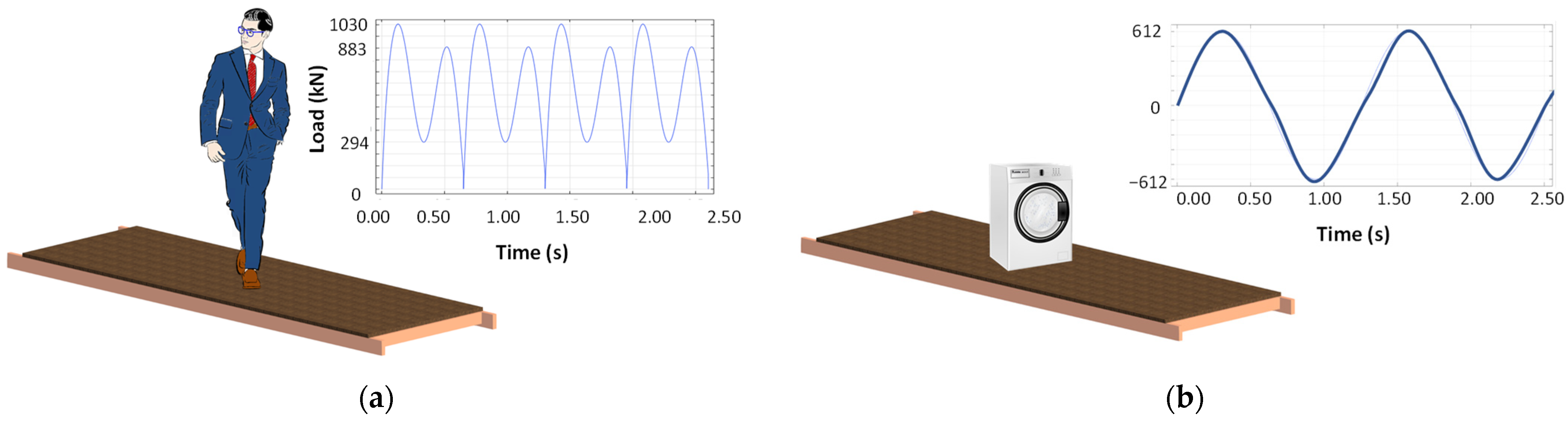
In this section, the different loading cases are presented. The first one is a walking time history of one person (Figure 5a), and the second one is the time history of a washing machine (Figure 5b).

Figure 5.
(a) Load function of human walking, and (b) load function of a washing machine.
- Walking time history
The harmonic load function of a person who is walking is presented in Equation (18), where each step is given with a polynomial function which is proposed by Harpel et al. [32]:
where is the load in terms of time ; is the acceleration of gravity; and to are coefficients depending on the walking frequency through previous experimental results [32]. Table 2 presents the values of these coefficients. In our study, the pacing frequency of walking () has been used, while the load duration, , is given using Equation (19).
Table 2.
Coefficients to for given walking frequency ().
- Washing machine time history
The harmonic load function of a washing machine is presented in Equation (20):
where is the load in terms of time ; is the initial load of the washing machine when it is full ( and is the angular frequency ( = 10 Hz).
4.2. Fundamental Frequencies
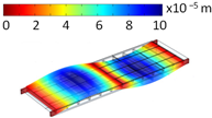
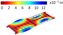
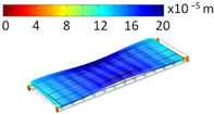
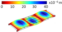
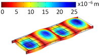
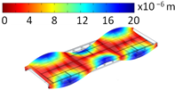
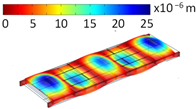
In this paragraph, the fundamental frequencies of the timber floor panel are presented. Table 3 compares the first nine fundamental frequencies of the panel for the different boundary conditions, hinge connection, and rigid connection (see detail 1 of Figure 1). The outcomes confirm that the panel with flexible boundary conditions has smaller eigenfrequencies than the panel with more rigid ones.
Table 3.
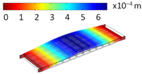
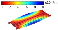
Modes shapes and eigenfrequencies.
4.3. Effect of Porous Material
In this section, the effects of the porous material on the vibroacoustic response of the system are presented. Porous materials with open cells consist of an elastic or rigid frame which is surrounded by air. The porosity, , is the ratio of the air volume, inside the sample, to the total volume, occupied by the porous material. Table 4 describes the main properties of the porous material that were used in this study [33,34].
Table 4.
Properties of porous material.
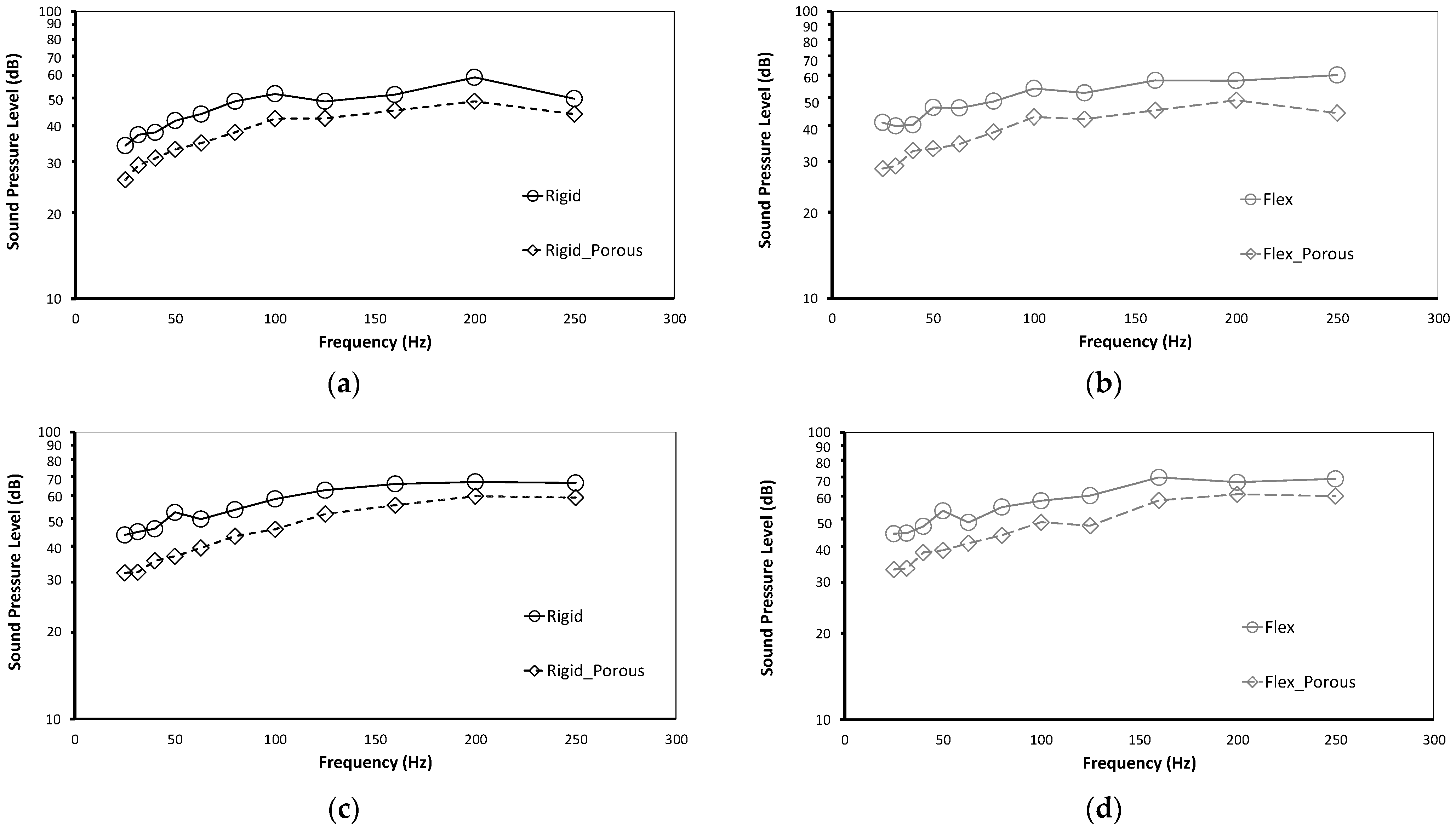
Figure 6 presents and compares the averages of 1/3-octave-band sound-pressure levels for the different loadings under two boundary conditions, with and without the presence of the porous material, within the frequency range of 25 to 250 Hz. The sound pressure has been calculated for all panels at the same exact point, at the center of the floor, i.e., the point of applied load. The results are shown for the following cases: rigid-connected panel under load walking (Figure 6a), hinge-connected panel under load walking (Figure 6b), rigid-connected panel under washing machine load (Figure 6c), and hinge-connected panel under washing machine load (Figure 6d).

Figure 6.
Comparison of a sound-pressure level in the 1/3 octave band at the middle point of the floor for (a) rigid connected panel submitted to load walking, (b) hinge connected panel submitted to load walking, (c) rigid connected panel submitted to washing machine load, and (d) hinge connected panel submitted to washing machine load.
It can be observed that regardless of the type of excitation and the boundary conditions applied to the floor, the incorporation of a layer of porous material leads to a significant reduction in the sound level by approximately 9 to 11 dB. On average, this represents an impressive reduction rate of about 18%. This remarkable reduction using the porous material can be attributed to its effective sound-absorbing properties. In fact, this material acts as an efficient barrier, absorbing and dissipating a substantial portion of sound energy within its complex microstructure. As sound waves encounter the porous layer, they undergo viscous and thermal losses within the material, thereby diminishing their intensity. This phenomenon remains consistent across the entire frequency range studied, resulting in a consistent transmission loss and lower sound-pressure levels for all tested cases. Moreover, the porous material not only contributes to sound attenuation but also plays a crucial role in vibration isolation and control. By effectively dampening structural vibrations induced by different types of excitation, such as load walking or washing machine operation, the porous layer further enhances the overall noise reduction achieved in the environment.
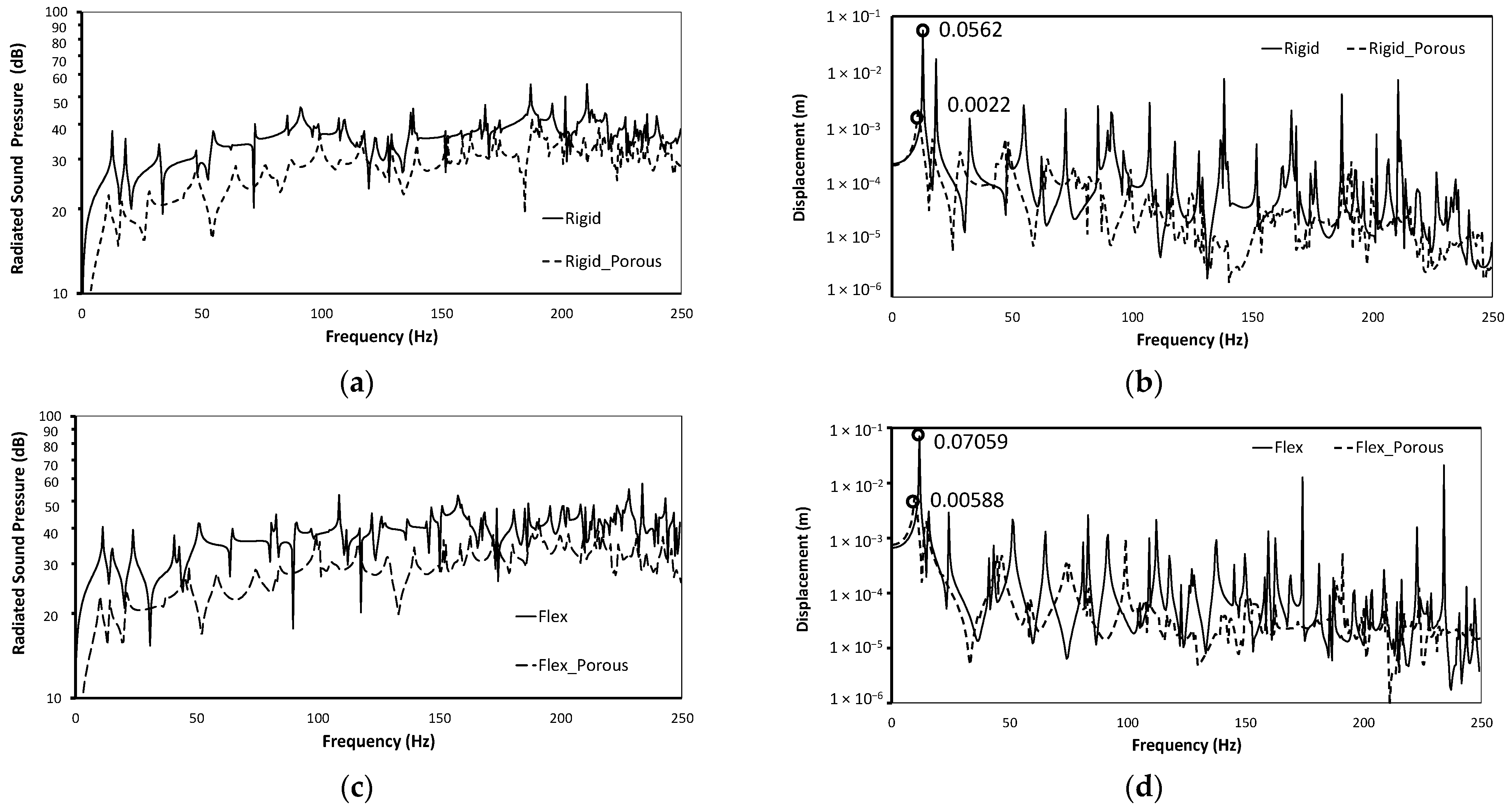
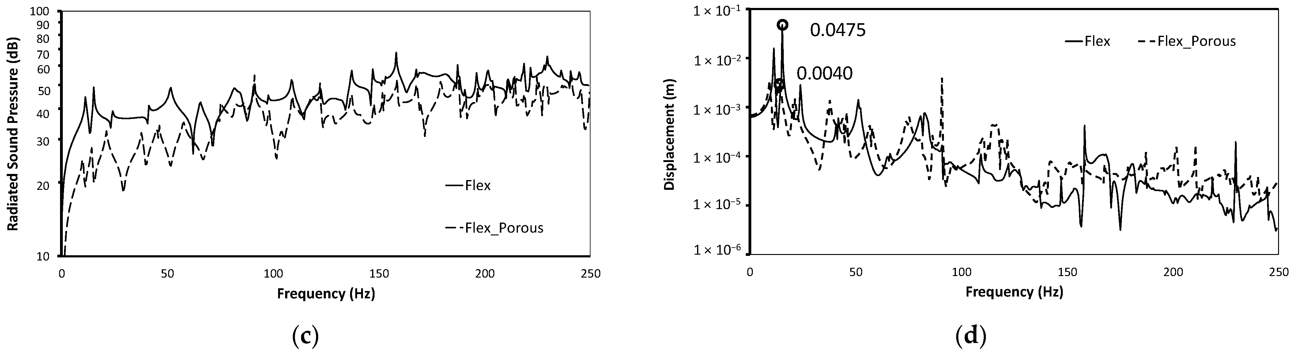
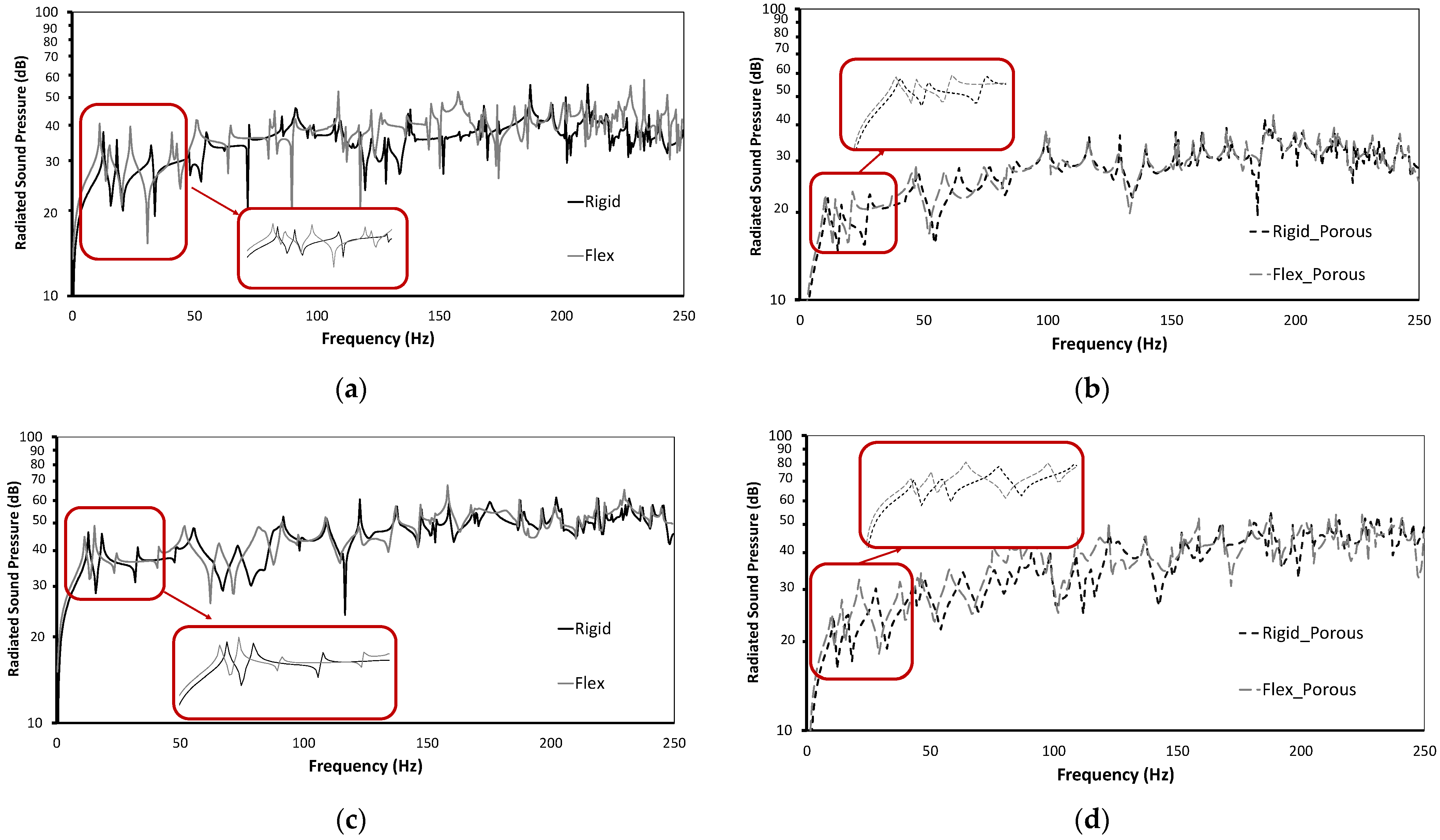
Figure 7a,c and Figure 8a,c present a comprehensive comparison, in narrow band representation, of the radiated sound pressure, while Figure 7b,d and Figure 8b,d show the vertical displacement at the middle point of the panel for two loading scenarios: the load walking and the washing machine loading, respectively. These figures reveal prominent max-amplitude peaks at specific frequencies, corresponding to the critical eigenfrequencies of the panel. These identified max-amplitude peaks represent the panel’s vibroacoustic response, indicating the frequencies where it exhibits its most significant vibrational and acoustic behavior. Both displacement and radiated acoustic pressure reach their peak at these specific eigenfrequencies, resulting in amplified vibrations and increased radiated-noise levels. The introduction of the porous material in the panel design leads to notable improvements in the vibroacoustic characteristics. One key observation is the slight shift in the critical eigenfrequencies caused by the presence of the porous layer. This shift indicates that the porous material influences the panel’s natural frequencies, potentially altering its modal behavior. Furthermore, the porous material acts as a shock absorber, effectively dampening vibrations within the panel structure, which leads to reduced sound radiation.

Figure 7.
Panel submitted to load walking, (a) comparison of a radiated sound pressure in the narrow band for rigid connection, (b) displacement at the middle point of the rigid panel, (c) comparison of a radiated sound pressure in the narrow band for hinge connection, and (d) displacement at the middle point of the hinge panel.
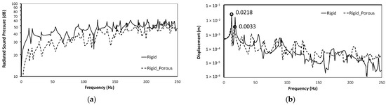

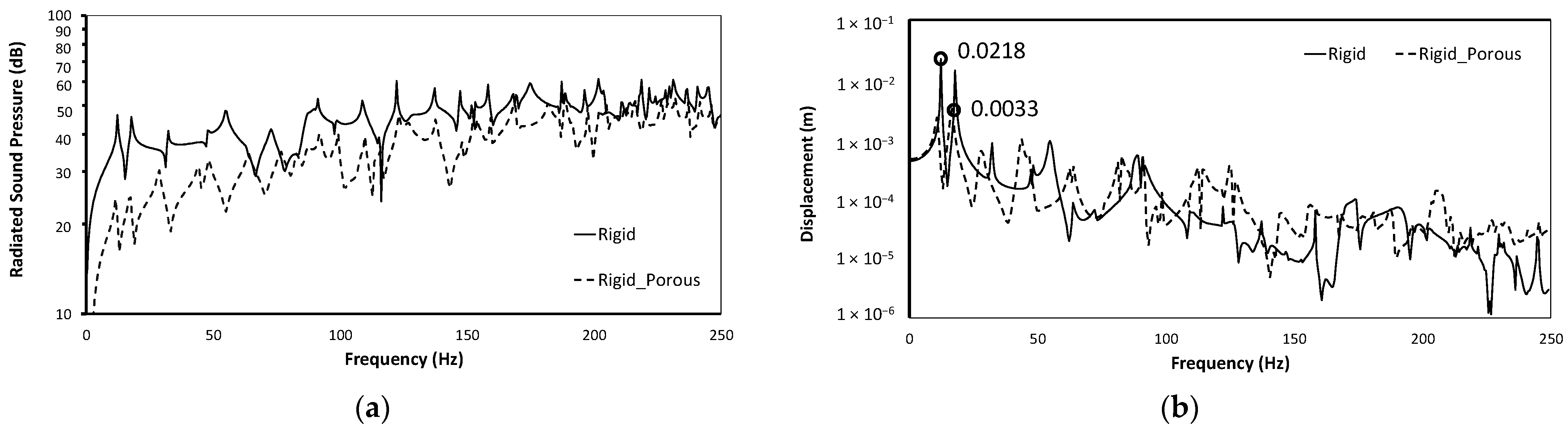
Figure 8.
Panel submitted to washing machine loading, (a) comparison of a radiated sound pressure in the narrow band for rigid connection, (b) displacement at the middle point of the rigid panel, (c) comparison of a radiated sound pressure in the narrow band for hinge connection, and (d) displacement at the middle point of the hinge panel.
The results reveal that the porous sound-absorbing material minimizes sound transmission and significantly reduces radiated sound energy when compared to the untreated system. This is owed to the porous sound-absorbing material’s damping effect on timber floor panels’ displacement, in which vibration energy is released as heat and absorbed by the porous sound-absorbing material’s solid skeleton. The porous sound-absorbing material also reduces noise due to thermal and viscous effects. It is possible to deduce that the porous sound-absorbing material plays a critical role in controlling the acoustic sound-pressure response, particularly for noise reduction in a coupled system. According to the findings, adding porous material can improve the acoustic performance of a timber floor panel in the low-frequency region.
4.4. Effect of Boundary Conditions
In this section, we analyze the effect of different boundary conditions on the narrowband radiated sound pressure of the panel. The comparisons are presented in Figure 8 for the following four different cases: the panel subjected to step load without porous material (Figure 9a), the panel with porous material subjected to step load (Figure 9b), the panel subjected to washing machine load without porous material (Figure 9c), and the panel with porous material subjected to washing machine load (Figure 9d). The results show that the boundary conditions have a noticeable impact on the resonance peaks, both with and without the presence of the porous material. This is consistent with the findings in Table 3, which present the natural frequencies of the system under different boundary conditions. However, despite these differences in resonance peaks, by analyzing these figures using third-octave band representations (not shown here for brevity), we observe that the boundary conditions do not significantly affect the acoustic power radiated by the structure. The reason behind this phenomenon lies in the effectiveness of the introduced porous material. By incorporating the porous layer, the panel gains sound-absorbing properties that effectively dampen vibrations and reduce sound radiation. This sound-absorbing capability is not significantly influenced by the boundary conditions, as demonstrated by the consistent acoustic power radiated by the structure across all cases.
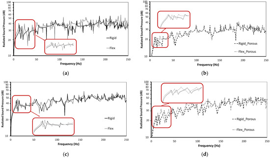
Figure 9.
Comparison of a radiated sound pressure in the narrow band for rigid and hinge connection for (a) panel submitted to load walking, (b) panel submitted to load walking with porous material, (c) panel submitted to washing machine load, and (d) panel with porous material submitted to washing machine load.
5. Conclusions
The purpose of this study aims to inquire into the effect of incorporating porous materials on noise and vibration reduction in wooden floor panels, as well as to analyze the vibroacoustic performance of the assembled panel under various types of excitation and boundary conditions, particularly in the lower frequency range. The research focuses on a timber floor panel assembled from glued laminated elements, such as beams, joists, and the wooden floor.
Here are the key scientific achievements and conclusions:
- Experimental tests are conducted to determine the mechanical properties of the glued laminated timber, and numerical models are developed using the finite element method (FEM). The material properties obtained from the experimental tests are used as input data in the FEM model to predict the behavior of the floor panel.
- A finite element formulation of sound radiation from an elastic structure with a poroelastic layer is presented. The poroelastic material is characterized using Biot theory, and its behavior is coupled with that of the elastic structure using a symmetrical coupling term. The porous material has two phases: solid and fluid, which are represented in the formulation by the displacement field for the solid phase and the pressure field for the fluid phase. This original approach has the benefit of lower computing costs and facilitates connectivity between all domains.
- The dynamic analyses and parametric study of the timber floor panel are performed considering different loading conditions and the presence of the porous material. The study shows that the incorporation of the porous layer leads to a significant reduction in sound levels (approximately 18%) by acting as an efficient sound absorber. The porous material not only attenuates sound but also dampens structural vibrations, contributing to improved overall noise reduction. This is owing to the porous sound-absorbing material’s damping effect on timber floor panels displacement, in which vibration energy is released as heat and absorbed by the porous sound-absorbing material’s solid skeleton. The porous sound-absorbing material also reduces noise due to thermal and viscous effects. Further research can focus on optimizing the properties of the porous material used in the floor panel to achieve maximum noise reduction.
Author Contributions
Both authors contributed to the design and implementation of the research, to the analysis of the results and to the writing of the manuscript. All authors have read and agreed to the published version of the manuscript.
Funding
This research received no external funding.
Institutional Review Board Statement
Not applicable.
Informed Consent Statement
Not applicable.
Data Availability Statement
Data sharing not applicable.
Conflicts of Interest
The authors declare no conflict of interest.
References
- Aloisio, A.; Pasca, D.; De Santis, Y.; Hillberger, T.; Giordano, P.; Rosso, M.; Tomasi, R.; Limongelli, M.; Bedon, C. Vibration issues in timber structures: A state-of-the-art review. J. Build. Eng. 2023, 76, 107098. [Google Scholar] [CrossRef]
- Rigobert, S.; Sgard, F.; Atalla, N. Investigation of dissipative effects in a poroelastic layer coated plate. J. Acoust. Soc. Am. 1999, 105, 1295. [Google Scholar] [CrossRef]
- Conta, S.; Homb, A. Sound radiation of hollow box timber floors under impact excitation: An experimental parameter study. Appl. Acoust. 2020, 161, 107190. [Google Scholar] [CrossRef]
- Titirla, M.; Michel, L.; Ferrier, E. Mechanical behavior of hybridal floor panels to timber columns joints. In Proceedings of the 9th International Conference on Fibre-Reinforced Polymer (FRP) Composites in Civil Engineering, CICE 2018, Paris, France, 17–19 July 2018. [Google Scholar]
- Titirla, M.; Benakli, S.; Larbi, W. Dynamic and vibroacoustic response of timber floor panels. Measurements and non-linear numerical simulations. In Proceedings of the 8th International Conference on Computational Methods in Structural Dynamics and Earthquake Engineering, COMPDYN 2021, Athens, Greece, 28–30 June 2021. [Google Scholar]
- CEN. 2004. EN 1995-1-1:2004; Eurocode 5: Design of Timber Structures. Part 1–1: General Common Rules and Rules for Buildings. European Committee for Standardization: Brussel, Belgium, 2004.
- Bachmann, H.; Ammann, W. Vibrations in Structures Induced by Man and Machines; IABSE—AIPC—IVBH: Zurich, Switzerland, 1987. [Google Scholar]
- Williams, M.S.; Waldron, P. Evaluation of methods for predicting occupantin-duced vibrations in concrete floors. Struct. Eng. 1994, 72, 334–340. [Google Scholar]
- Da Silva, J.G.S.; da SVellasco, P.C.G.; de Andrade, S.A.L.; da Soeiro, F.J.C.P.; Werneck, R.N. An evaluation of the dynamical performance of composite slabs. Comput. Struct. 2003, 81, 1905–1913. [Google Scholar] [CrossRef]
- Hicks, S. Vibration characteristics of steel-concrete composite floor system. Prog. Struct. Eng. Mater. 2004, 4, 21–38. [Google Scholar] [CrossRef]
- Ebrahimpour, A.; Sack, R.L. A review of vibration serviceability criteria for-floor structures. Comput. Struct. 2005, 83, 2488–2494. [Google Scholar] [CrossRef]
- Bernard, E.S. Dynamic serviceability in lightweight engineered timber floors. ASCE J. Struct. Eng. 2008, 134, 258–268. [Google Scholar] [CrossRef]
- Yang, Y.; Fenemore, C.; Kingan, M.; Mac, B. Analysis of the vibroacoustic characteristics of cross laminated timber panels using a wave and finite element method. J. Sound Vib. 2021, 494, 115842. [Google Scholar] [CrossRef]
- Caniato, M.; Bettarello, F.; Fausti, P.; Ferluga, A.; Marsich, L.; Schmid, C. Impact sound of timber floors in sustainable buildings. Build. Environ. 2017, 120, 110–122. [Google Scholar] [CrossRef]
- Filippoupolitis, M.; Hopkins, C.; Völtl, R.; Schanda, U.; Mahn, J.; Krajči, L. Structural dynamics of a dowelled-joist timber floor in the low-frequency range modelled using finite element simulation. Eng. Struct. 2017, 148, 602–620. [Google Scholar]
- Proença, M.; Neves e Sousa, A.; Garrido, M.; Correia, J.R. Acoustic performance of composite sandwich panels for building floors: Experimental tests and numerical-analytical simulation. J. Build. Eng. 2020, 32, 101751. [Google Scholar]
- Granzotto, N.; Arianna Marzi, A.; Gasparella, A. Cross-Laminated Timber Floor: Analysis of the Acoustic Properties and Radiation Efficiency. Appl. Sci. 2022, 12, 3233. [Google Scholar] [CrossRef]
- Titirla, M.; Ferrier, E.; Michel, L. On the mechanical behaviour of innovative moment connections between composite floor panels and glulam columns. Int. J. Archit. Herit.-Conserv. Anal. Restor. 2021, 15, 321–333. [Google Scholar]
- EN 1194:1999; Timber Structures—Glued Laminated Timber—Strength Classes and Determination of Characteristic Values (Withdrawn), 1999. British Standards Institution: London, UK, 1999.
- EN 384; Structural Timber—Determination of Characteristic Values of Mechanical Proper-Ties and Density; CEN/TC 124. British Standards Institution: London, UK, 2016.
- Allard, J.F.; Atalla, N. Propagation of Sound in Porous Media: Modelling Sound Absorbing Materials, 2nd ed.; John Wiley & Sons: Hoboken, NJ, USA, 2009. [Google Scholar]
- Larbi, W.; Deü, J.-F.; Ohayon, R. Vibroacoustic analysis of double-wall sandwich panels with viscoelastic core. Comput. Struct. 2016, 174, 92–103. [Google Scholar]
- Panneton, R.; Atalla, N. Numerical prediction of sound transmission through finite multilayer systems with poroelastic materials. J. Acoust. Soc. Am. 1996, 100, 346–354. [Google Scholar]
- Atalla, N.; Hamdi, M.A.; Panneton, R. Enhanced weak integral formulation for the mixed (u, p) poroelastic equations. J. Acoust. Soc. Am. 2001, 109, 3065–30684. [Google Scholar]
- Atalla, N.; Panneton, R.; Debergue, O. A mixed displacement-pressure formulation for poroelastic materials. J. Acoust. Soc. Am. 1998, 104, 1444–1452. [Google Scholar]
- Larbi, W. Numerical modeling of sound and vibration reduction using viscoelastic materials and shunted piezoelectric patches. Comput. Struct. 2020, 232, 105822. [Google Scholar]
- Larbi, W.; Deü, J.-F.; Ohayon, R. Finite element reduced order model for noise and vibration reduction of double sandwich panels using shunted piezoelectric patches. Appl. Acoust. 2016, 108, 40–49. [Google Scholar]
- Fahy, F.; Gardonio, P. Sound and Structural Vibration, Radiation, Transmission and Response, 2nd ed.; Academic Press Inc.: Cambridge, MA, USA, 2006. [Google Scholar]
- Harper, C.; Warlow, W.J.; Clarke, B.L. The forces applied to the floor by the foot in walking. Wear 1961, 4, 495–497. [Google Scholar]
- Elliott, S.J.; Johnson, M.E. Radiation modes and the active control of sound power. J. Acoust. Soc. Am. 1993, 94, 2194–2204. [Google Scholar] [CrossRef]
- Fuller, C.C.; Elliott, S.; Nelson, P.A. Nelson, Active Control of Vibration; Academic Press: London, UK, 1996. [Google Scholar]
- Larbi, W.; Pereira da Silva, L.; Deü, J.-F. An efficient FE approach for attenuation of acoustic radiation of thin structures by using passive shunted piezoelectric systems. Appl. Acoust. 2017, 128, 3–13. [Google Scholar]
- Groby, J.-P.; Ogam, E.; De Ryck, L.; Sebaa, N.; Lauriks, W. Analytical method for the ultrasonic characterization of homogeneous rigid porous materials from transmitted and reflected coefficients. J. Acoust. Soc. Am. 2010, 127, 764–772. [Google Scholar]
- Yang, T.; Saati, F.; Groby, J.-P.; Xiong, X.; Petrů, M.; Mishra, R.; Militký, J.; Marburg, S. Characterization on Polyester Fibrous Panels and Their Homogeneity Assessment. Polymers 2020, 12, 2098. [Google Scholar] [PubMed]


Disclaimer/Publisher’s Note: The statements, opinions and data contained in all publications are solely those of the individual author(s) and contributor(s) and not of MDPI and/or the editor(s). MDPI and/or the editor(s) disclaim responsibility for any injury to people or property resulting from any ideas, methods, instructions or products referred to in the content. |
© 2023 by the authors. Licensee MDPI, Basel, Switzerland. This article is an open access article distributed under the terms and conditions of the Creative Commons Attribution (CC BY) license (https://creativecommons.org/licenses/by/4.0/).