
3D-Printed Bio-Inspired Mechanisms for Bird-like Morphing Drones

 ,
, 
Abstract
:Featured Application
Abstract
1. Introduction
2. Materials and Methods
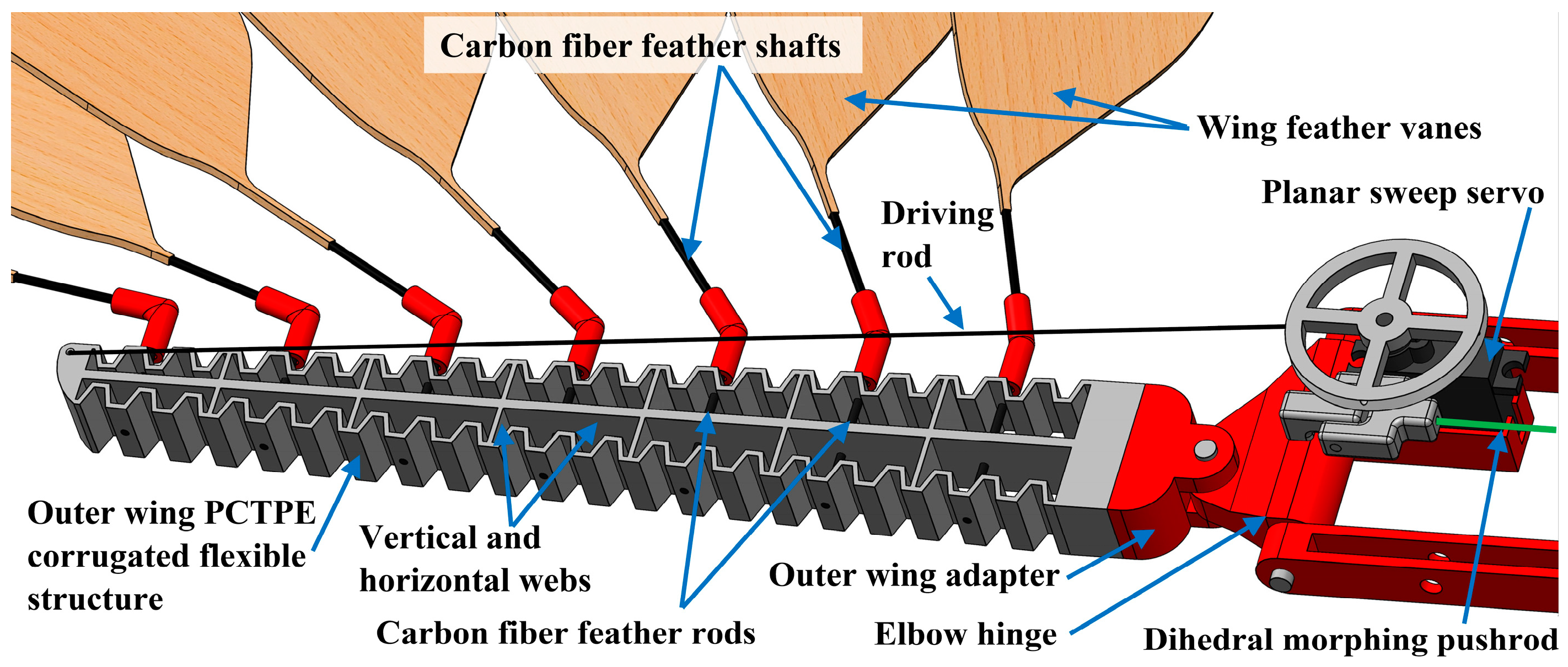
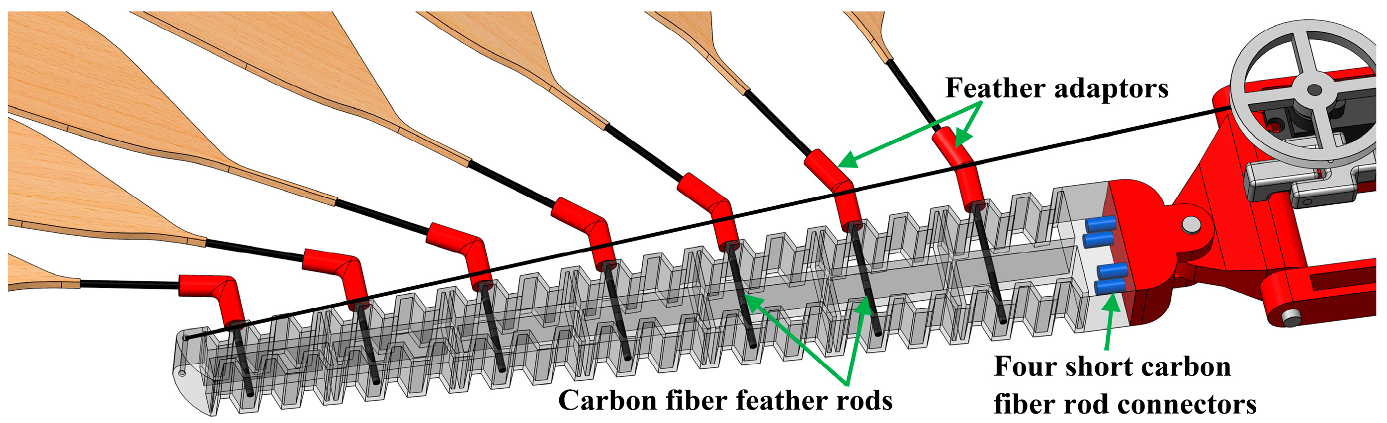
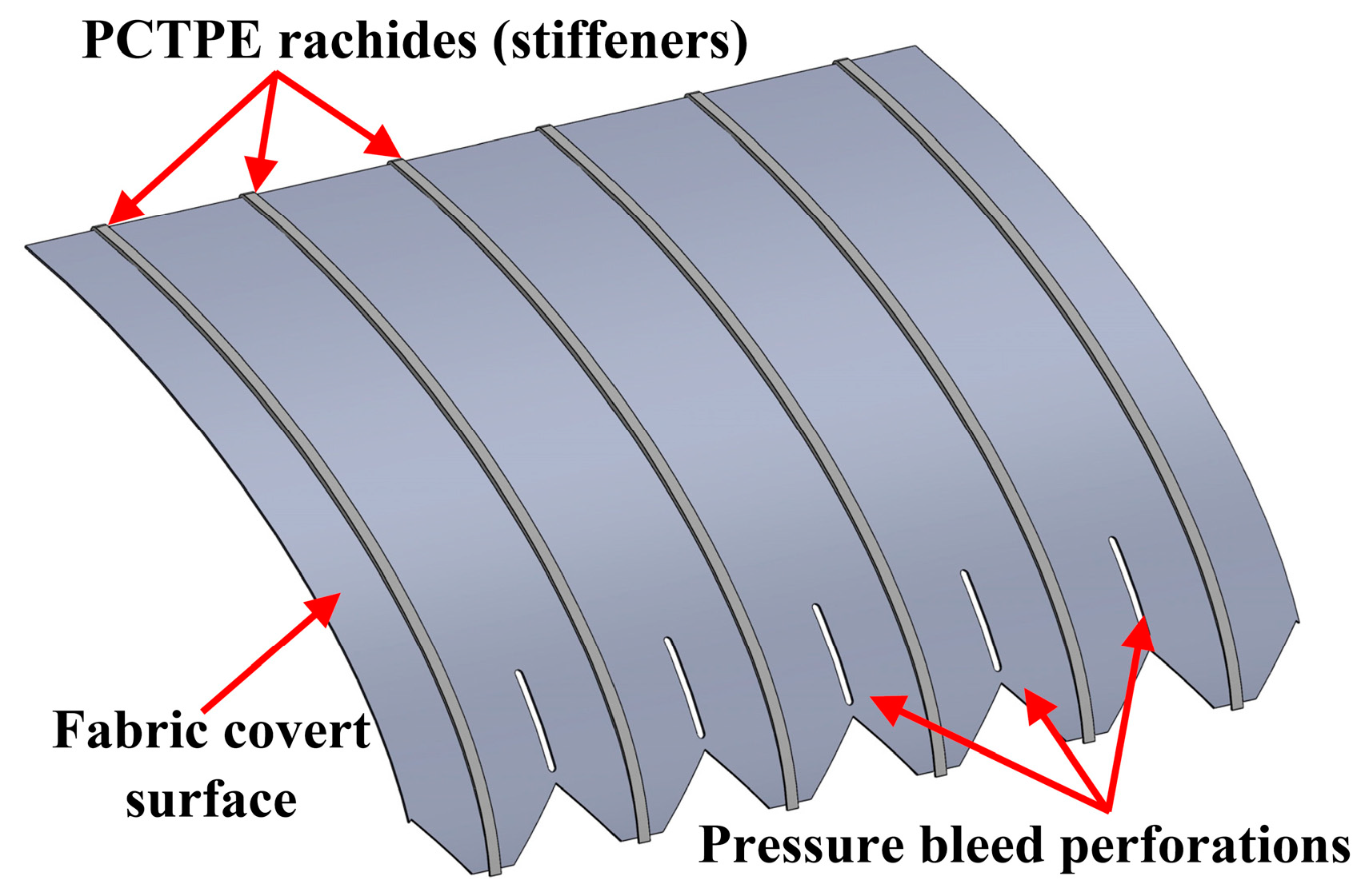
2.1. Wing Design
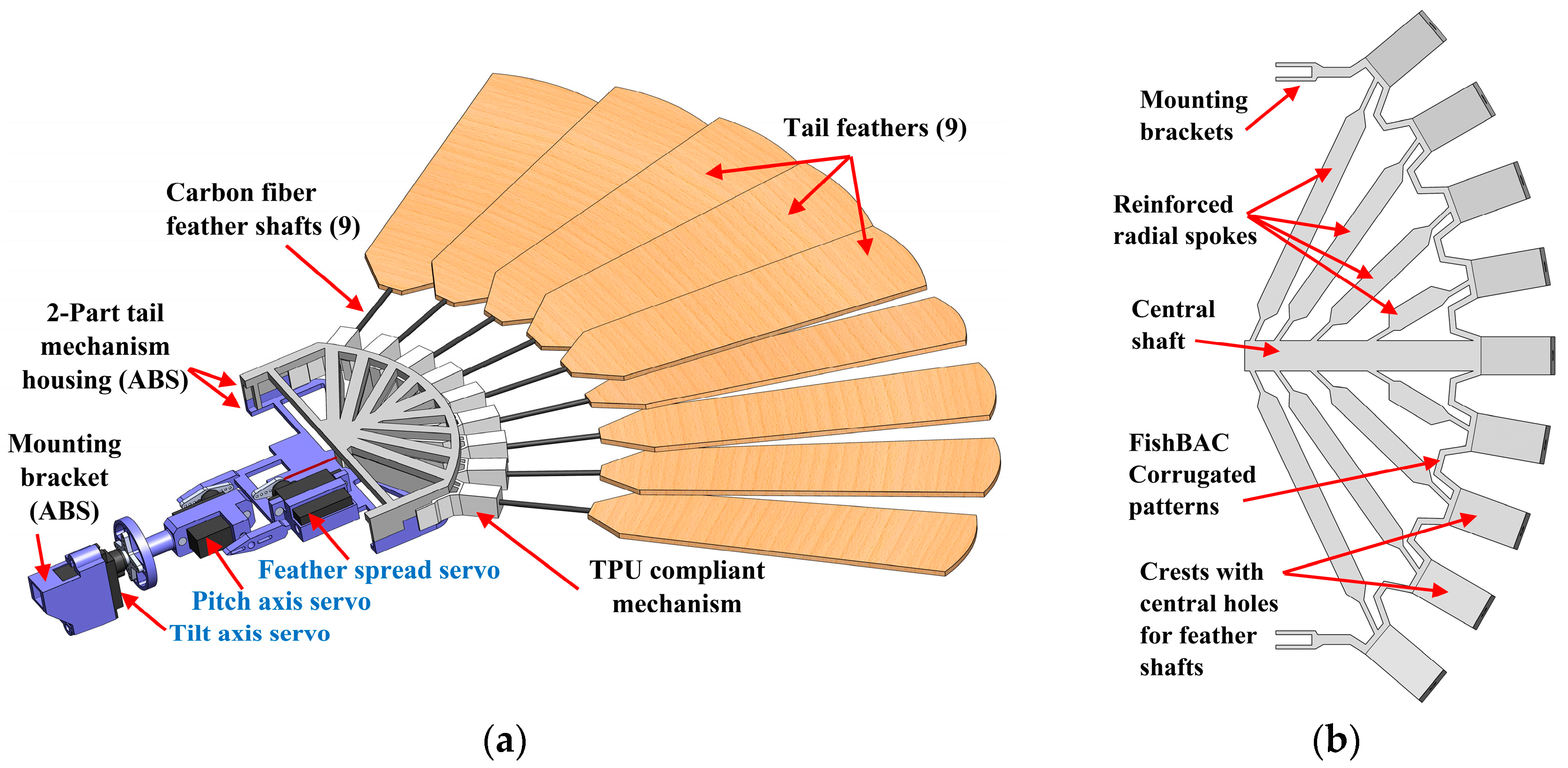
2.2. Tail Design
3. Results
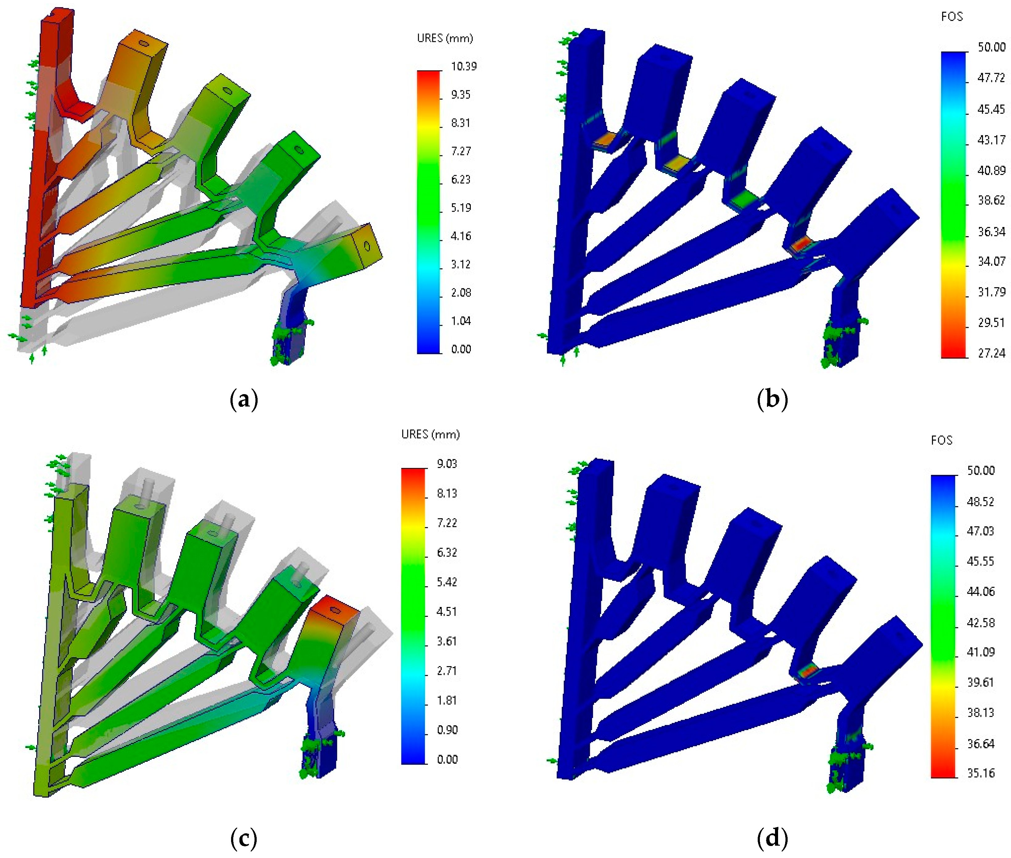
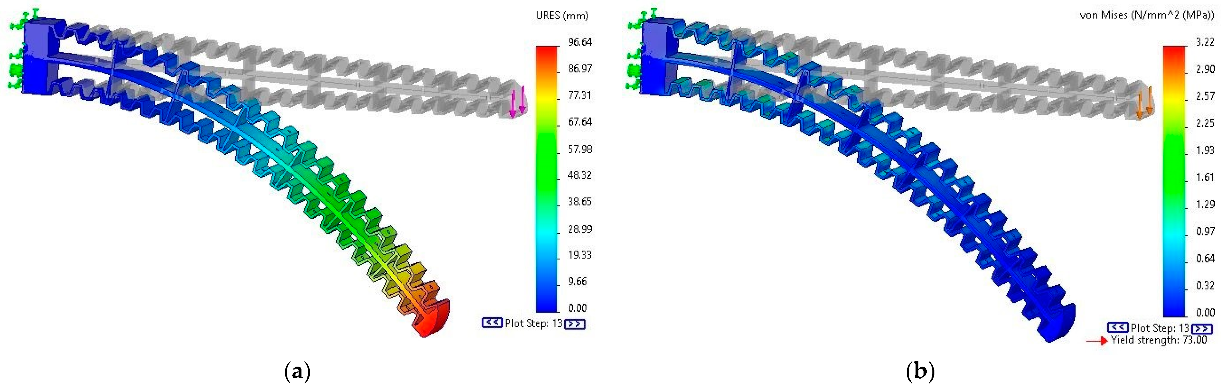
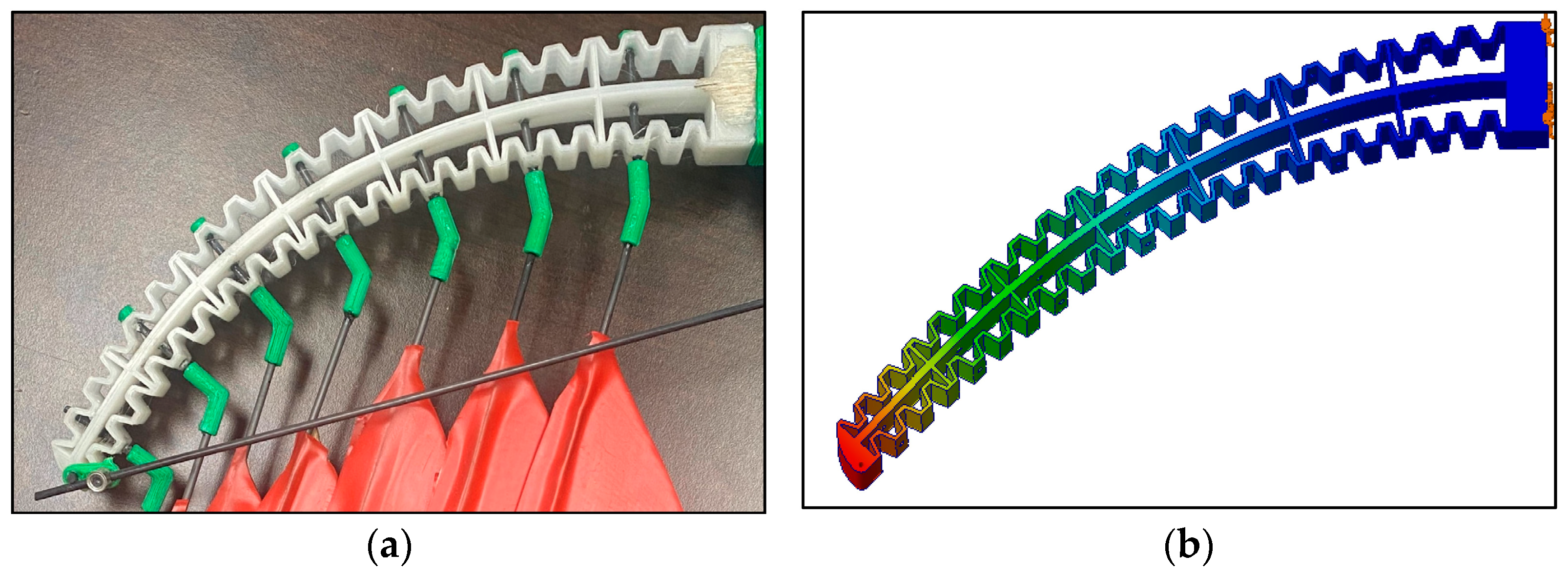
3.1. Finite Element Analyses
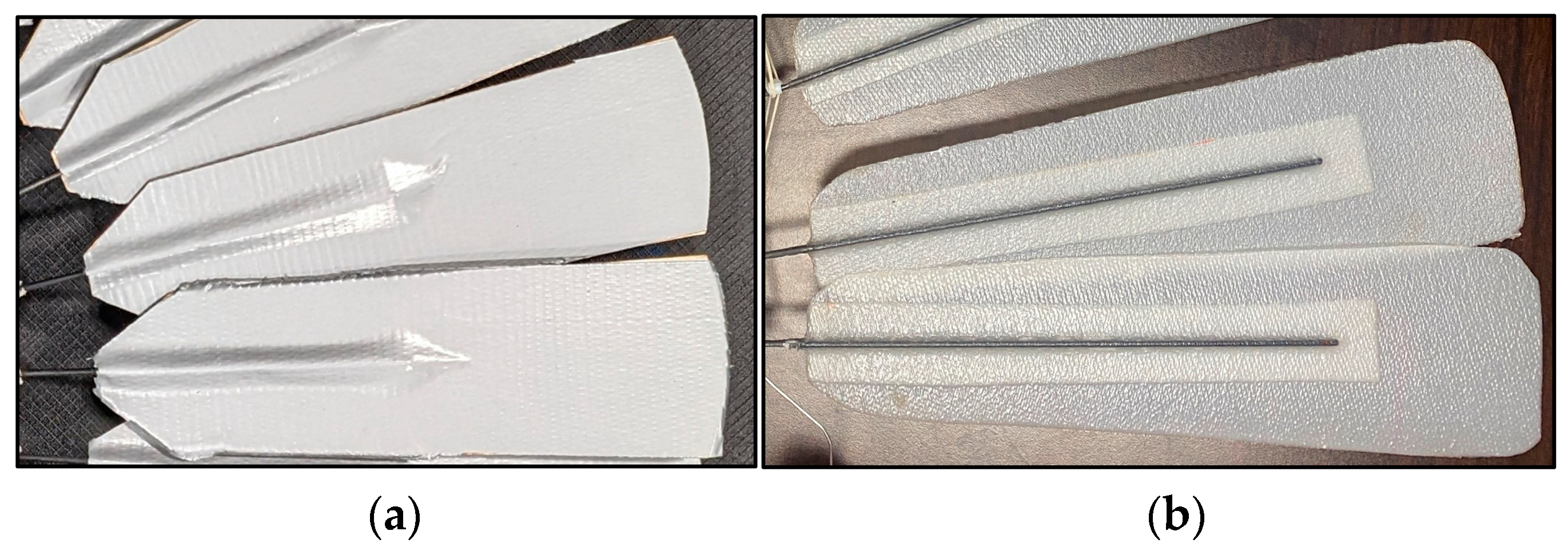
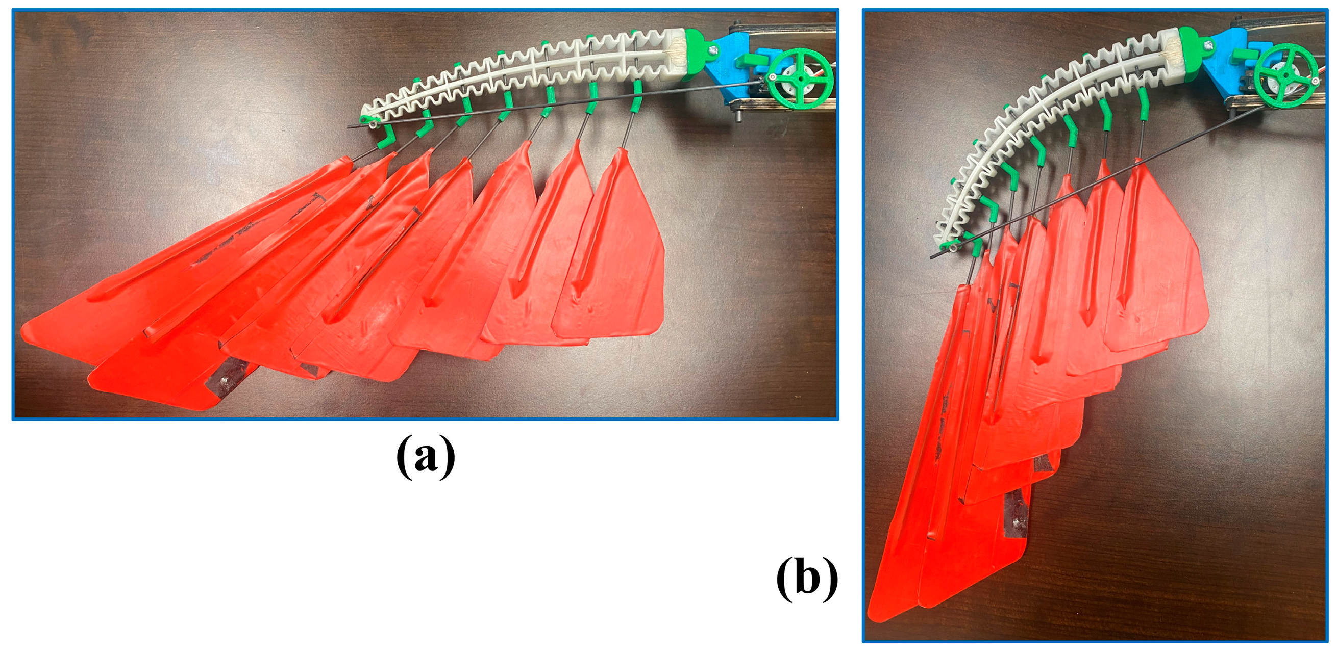
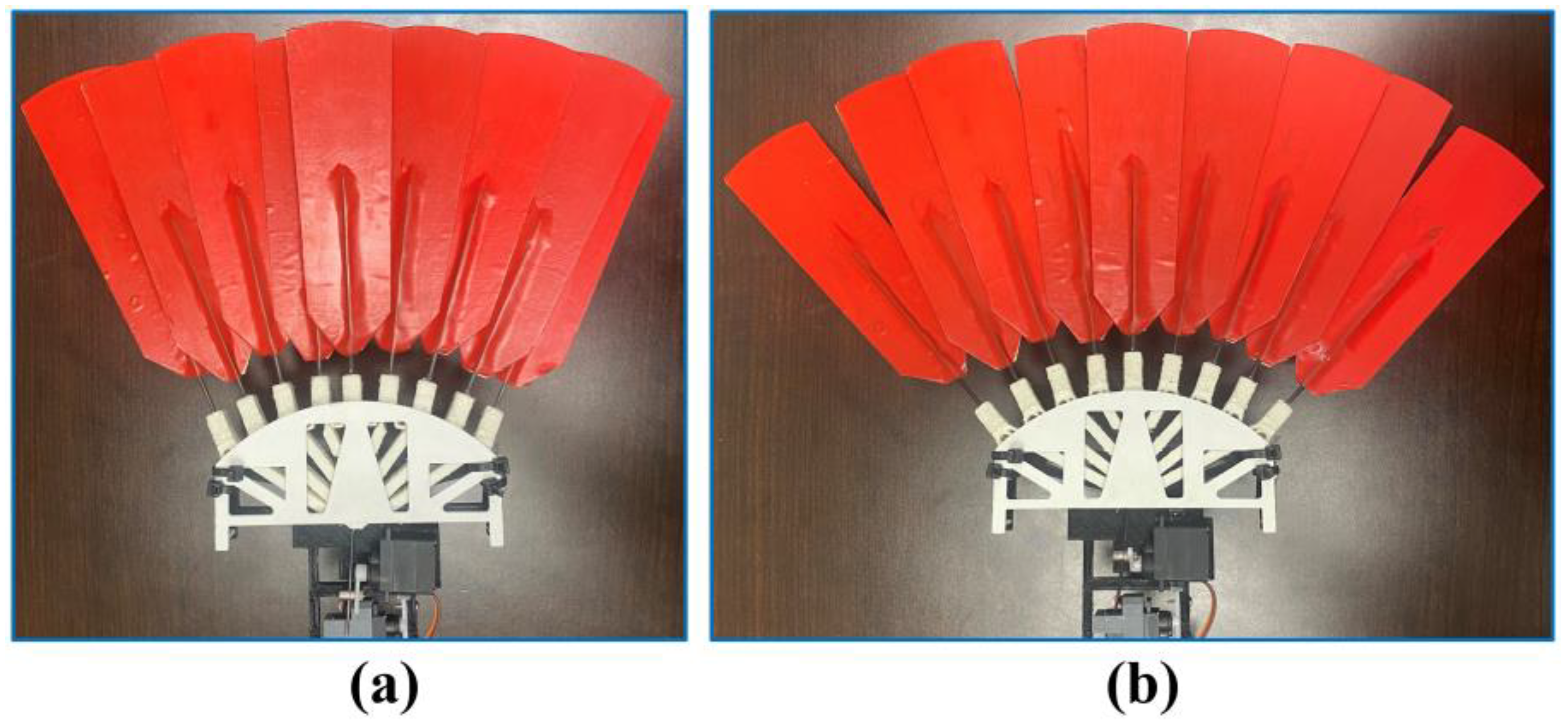
3.2. Manufacturing and Testing
4. Discussion and Conclusions
Supplementary Materials
Author Contributions
Funding
Institutional Review Board Statement
Informed Consent Statement
Data Availability Statement
Acknowledgments
Conflicts of Interest
References
- Han, J.; Hui, Z.; Tian, F.; Chen, G. Review on Bio-Inspired Flight Systems and Bionic Aerodynamics. Chin. J. Aeronaut. 2021, 34, 170–186. [Google Scholar] [CrossRef]
- Barbarino, S.; Bilgen, O.; Ajaj, R.M.; Friswell, M.I.; Inman, D.J. A Review of Morphing Aircraft. J. Intell. Mater. Syst. Struct. 2011, 22, 823–877. [Google Scholar] [CrossRef]
- Sofla, A.Y.N.; Meguid, S.A.; Tan, K.T.; Yeo, W.K. Shape Morphing of Aircraft Wing: Status and Challenges. Mater. Des. 2010, 31, 1284–1292. [Google Scholar] [CrossRef]
- Min, Z.; Kien, V.K.; Richard, L.J.Y. Aircraft Morphing Wing Concepts with Radical Geometry Change. IES J. Part A Civ. Struct. Eng. 2010, 3, 188–195. [Google Scholar] [CrossRef]
- Gomez, J.C.; Garcia, E. Morphing Unmanned Aerial Vehicles. Smart Mater. Struct. 2011, 20, 103001. [Google Scholar] [CrossRef]
- Sun, J.; Guan, Q.; Liu, Y.; Leng, J. Morphing Aircraft Based on Smart Materials and Structures: A State-of-the-Art Review. J. Intell. Mater. Syst. Struct. 2016, 27, 2289–2312. [Google Scholar] [CrossRef]
- Joshi, S.; Tidwell, Z.; Crossley, W.; Ramakrishnan, S. Comparison of Morphing Wing Stategies Based upon Aircraft Performance Impacts. In Proceedings of the 45th AIAA/ASME/ASCE/AHS/ASC Structures, Structural Dynamics & Materials Conference, Palm Springs, CA, USA, 19–22 April 2004. [Google Scholar]
- Ajaj, R.M.; Jankee, G.K. The Transformer Aircraft: A Multimission Unmanned Aerial Vehicle Capable of Symmetric and Asymmetric Span Morphing. Aerosp. Sci. Technol. 2018, 76, 512–522. [Google Scholar] [CrossRef]
- Schlup, A.; Bishay, P.; Mclennan, T.; Barajas, C.; Talebian, B.; Thatcher, G.; Flores, R.; Perez-Norwood, J.; Torres, C.; Kibret, K.; et al. MataMorph 2: A New Experimental UAV with Twist-Morphing Wings and Camber-Morphing Tail Stabilizers. In Proceedings of the AIAA Scitech 2021 Forum, Virtual, 11 January 2021. [Google Scholar]
- Bishay, P.L.; Kok, J.S.; Ferrusquilla, L.J.; Espinoza, B.M.; Heness, A.; Buendia, A.; Zadoorian, S.; Lacson, P.; Ortiz, J.D.; Basilio, R.; et al. Design and Analysis of MataMorph-3: A Fully Morphing UAV with Camber-Morphing Wings and Tail Stabilizers. Aerospace 2022, 9, 382. [Google Scholar] [CrossRef]
- Harvey, C.; Gamble, L.L.; Bolander, C.R.; Hunsaker, D.F.; Joo, J.J.; Inman, D.J. A Review of Avian-Inspired Morphing for UAV Flight Control. Prog. Aerosp. Sci. 2022, 132, 100825. [Google Scholar] [CrossRef]
- Mackenzie, D. A Flapping of Wings. Science 2012, 335, 1430–1433. [Google Scholar] [CrossRef]
- Ajanic, E.; Feroskhan, M.; Mintchev, S.; Noca, F.; Floreano, D. Bioinspired Wing and Tail Morphing Extends Drone Flight Capabilities. Sci. Robot. 2020, 5, eabc2897. [Google Scholar] [CrossRef] [PubMed]
- Ajanic, E.; Feroskhan, M.; Wüest, V.; Floreano, D. Sharp Turning Maneuvers with Avian-Inspired Wing and Tail Morphing. Commun. Eng. 2022, 1, 34. [Google Scholar] [CrossRef]
- Chang, E.; Matloff, L.Y.; Stowers, A.K.; Lentink, D. Soft Biohybrid Morphing Wings with Feathers Underactuated by Wrist and Finger Motion. Sci. Robot. 2020, 5, eaay1246. [Google Scholar] [CrossRef]
- Ajaj, R.M.; Beaverstock, C.S.; Friswell, M.I. Morphing Aircraft: The Need for a New Design Philosophy. Aerosp. Sci. Technol. 2016, 49, 154–166. [Google Scholar] [CrossRef]
- Parker, G.; Borbone, J. Wing and Gliding Dynamics of a Flapping Winged Ornithopter. In Proceedings of the 2010 World Automation Congress, Kobe, Japan, 19–23 September 2010; pp. 1–5. [Google Scholar]
- Usherwood, J.R.; Cheney, J.A.; Song, J.; Windsor, S.P.; Stevenson, J.P.J.; Dierksheide, U.; Nila, A.; Bomphrey, R.J. High Aerodynamic Lift from the Tail Reduces Drag in Gliding Raptors. J. Exp. Biol. 2020, 223, jeb214809. [Google Scholar] [CrossRef]
- Murayama, Y.; Nakata, T.; Liu, H. Aerodynamic Performance of a Bird-Inspired Morphing Tail. J. Biomech. Sci. Eng. 2023, 18, 22-00340. [Google Scholar] [CrossRef]
- Liu, T.; Kuykendoll, K.; Rhew, R.; Jones, S. Avian Wings. In Proceedings of the 24th AIAA Aerodynamic Measurement Technology and Ground Testing Conference, Portland, OR, USA, 28 June 2004. [Google Scholar]
- Shepard, E.L.C.; Williamson, C.; Windsor, S.P. Fine-Scale Flight Strategies of Gulls in Urban Airflows Indicate Risk and Reward in City Living. Phil. Trans. R. Soc. B 2016, 371, 20150394. [Google Scholar] [CrossRef]
- Harvey, C.; Baliga, V.B.; Lavoie, P.; Altshuler, D.L. Wing Morphing Allows Gulls to Modulate Static Pitch Stability during Gliding. J. R. Soc. Interface 2019, 16, 20180641. [Google Scholar] [CrossRef]
- Harvey, C.; Baliga, V.B.; Goates, C.D.; Hunsaker, D.F.; Inman, D.J. Gull-Inspired Joint-Driven Wing Morphing Allows Adaptive Longitudinal Flight Control. J. R. Soc. Interface 2021, 18, 20210132. [Google Scholar] [CrossRef]
- Harvey, C.; Inman, D.J. Gull Dynamic Pitch Stability Is Controlled by Wing Morphing. Proc. Natl. Acad. Sci. USA 2022, 119, e2204847119. [Google Scholar] [CrossRef]
- Meyer, R.; Hage, W.; Bechert, D.W.; Schatz, M.; Knacke, T.; Thiele, F. Separation Control by Self-Activated Movable Flaps. AIAA J. 2007, 45, 191–199. [Google Scholar] [CrossRef]
- Bishay, P.L.; Finden, R.; Recinos, S.; Alas, C.; Lopez, E.; Aslanpour, D.; Flores, D.; Gonzalez, E. Development of an SMA-Based Camber Morphing UAV Tail Core Design. Smart Mater. Struct. 2019, 28, 075024. [Google Scholar] [CrossRef]
- Bechert, D.W.; Bruse, M.; Hage, W.; Meyer, R. Fluid Mechanics of Biological Surfaces and Their Technological Application. Naturwissenschaften 2000, 87, 157–171. [Google Scholar] [CrossRef]
- Ponitz, B.; Triep, M.; Brücker, C. Aerodynamics of the Cupped Wings during Peregrine Falcon’s Diving Flight. Open J. Fluid Dyn. 2014, 4, 363–372. [Google Scholar] [CrossRef]
- Ponitz, B.; Schmitz, A.; Fischer, D.; Bleckmann, H.; Brücker, C. Diving-Flight Aerodynamics of a Peregrine Falcon (Falco Peregrinus). PLoS ONE 2014, 9, e86506. [Google Scholar] [CrossRef] [PubMed]
- Pons, J.-M.; Hassanin, A.; Crochet, P.-A. Phylogenetic Relationships within the Laridae (Charadriiformes: Aves) Inferred from Mitochondrial Markers. Mol. Phylogen. Evol. 2005, 37, 686–699. [Google Scholar] [CrossRef] [PubMed]
- Baliga, V.B.; Szabo, I.; Altshuler, D.L. Range of Motion in the Avian Wing Is Strongly Associated with Flight Behavior and Body Mass. Sci. Adv. 2019, 5, eaaw6670. [Google Scholar] [CrossRef]
- Gatesy, S.M.; Dial, K.P. From Frond to Fan: Archaeopteryx and the Evolution of Short-Tailed Birds. Evolution 1996, 50, 2037–2048. [Google Scholar] [CrossRef]
- Zusi, R.L.; Gill, F.B. The Marvelous Tail of Loddigesia mirabilis (Trochilidae). Auk 2009, 126, 590–603. [Google Scholar] [CrossRef]


| Young’s Modulus, E [MPa] | Poisson’s Ratio, υ | Yield Strength, σy [MPa] | |
|---|---|---|---|
| PCTPE | 73 | 0.392 | 73 |
| TPU | 40 | 0.394 | 79.3 |
Disclaimer/Publisher’s Note: The statements, opinions and data contained in all publications are solely those of the individual author(s) and contributor(s) and not of MDPI and/or the editor(s). MDPI and/or the editor(s) disclaim responsibility for any injury to people or property resulting from any ideas, methods, instructions or products referred to in the content. |
© 2023 by the authors. Licensee MDPI, Basel, Switzerland. This article is an open access article distributed under the terms and conditions of the Creative Commons Attribution (CC BY) license (https://creativecommons.org/licenses/by/4.0/).
Share and Cite
Bishay, P.L.; Brody, M.; Podell, D.; Corte Garcia, F.; Munoz, E.; Minassian, E.; Bradley, K. 3D-Printed Bio-Inspired Mechanisms for Bird-like Morphing Drones. Appl. Sci. 2023, 13, 11814. https://doi.org/10.3390/app132111814
Bishay PL, Brody M, Podell D, Corte Garcia F, Munoz E, Minassian E, Bradley K. 3D-Printed Bio-Inspired Mechanisms for Bird-like Morphing Drones. Applied Sciences. 2023; 13(21):11814. https://doi.org/10.3390/app132111814
Chicago/Turabian StyleBishay, Peter L., Matthew Brody, David Podell, Francisco Corte Garcia, Erik Munoz, Evette Minassian, and Kevin Bradley. 2023. "3D-Printed Bio-Inspired Mechanisms for Bird-like Morphing Drones" Applied Sciences 13, no. 21: 11814. https://doi.org/10.3390/app132111814
APA StyleBishay, P. L., Brody, M., Podell, D., Corte Garcia, F., Munoz, E., Minassian, E., & Bradley, K. (2023). 3D-Printed Bio-Inspired Mechanisms for Bird-like Morphing Drones. Applied Sciences, 13(21), 11814. https://doi.org/10.3390/app132111814