
An Improved Two-Dimensional Simplification Calculation Method for Axial Flux Permanent Magnet Synchronous Motor


Abstract
:1. Introduction
2. Existing Equivalent Methods for APMSM
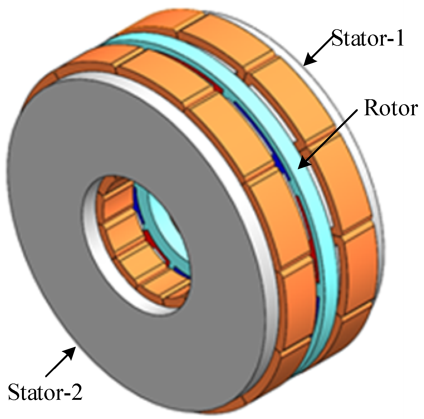
2.1. Three-Dimensional Structure of Axial Flux Permanent Magnet Synchronous Motors
2.2. Existing Equivalent Methods Based on 2D Multi-Layer Linear Permanent Magnet Synchronous Motors
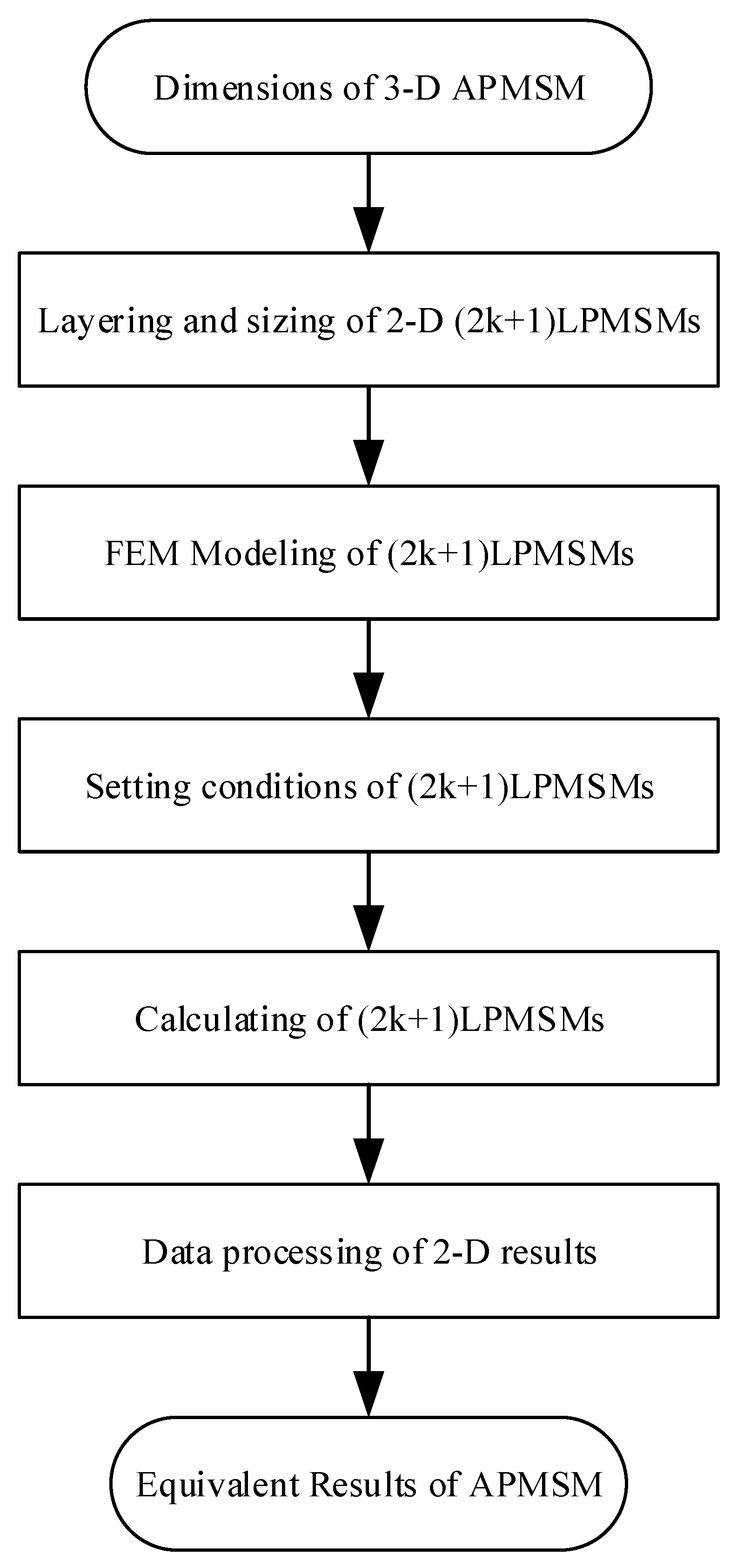
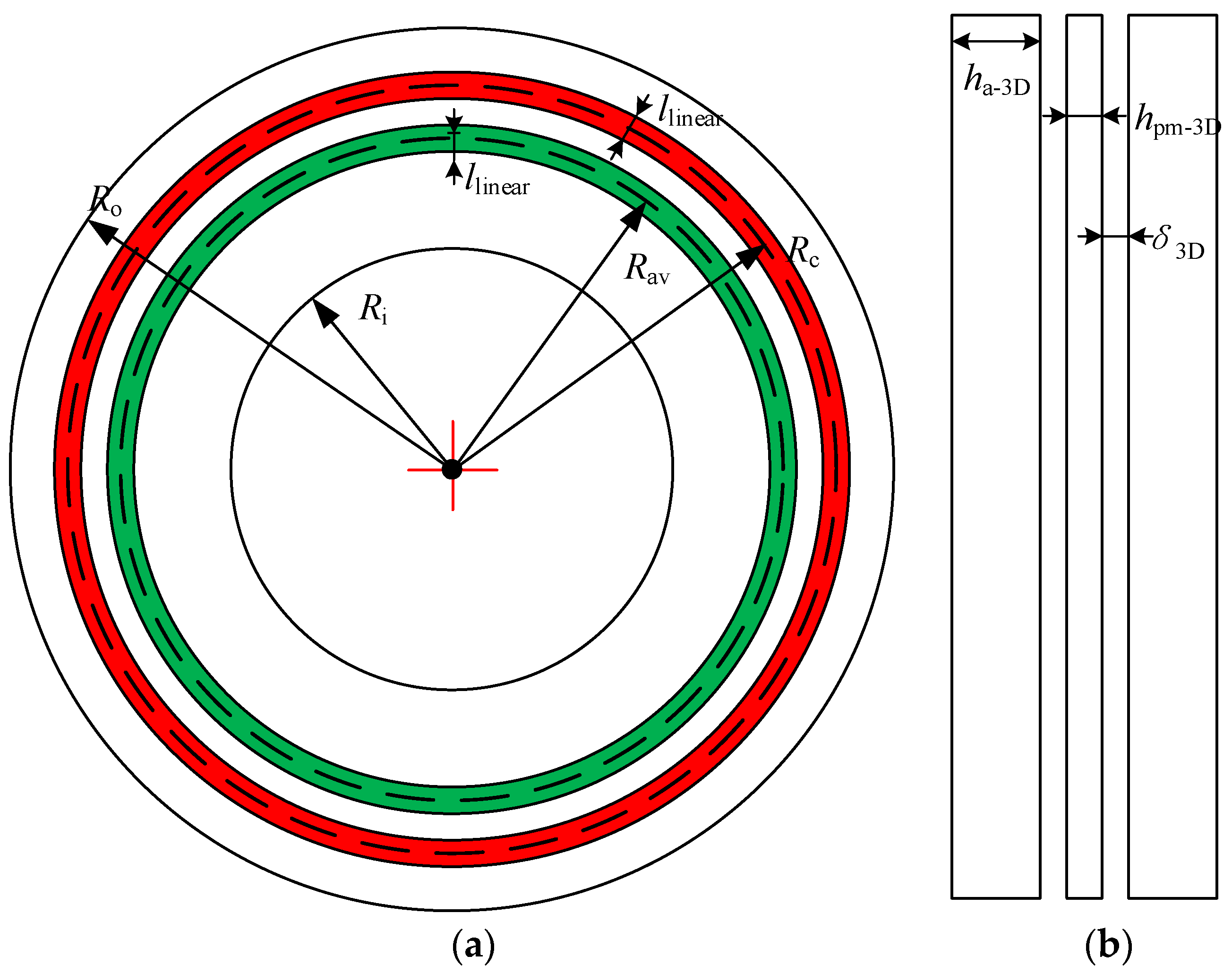
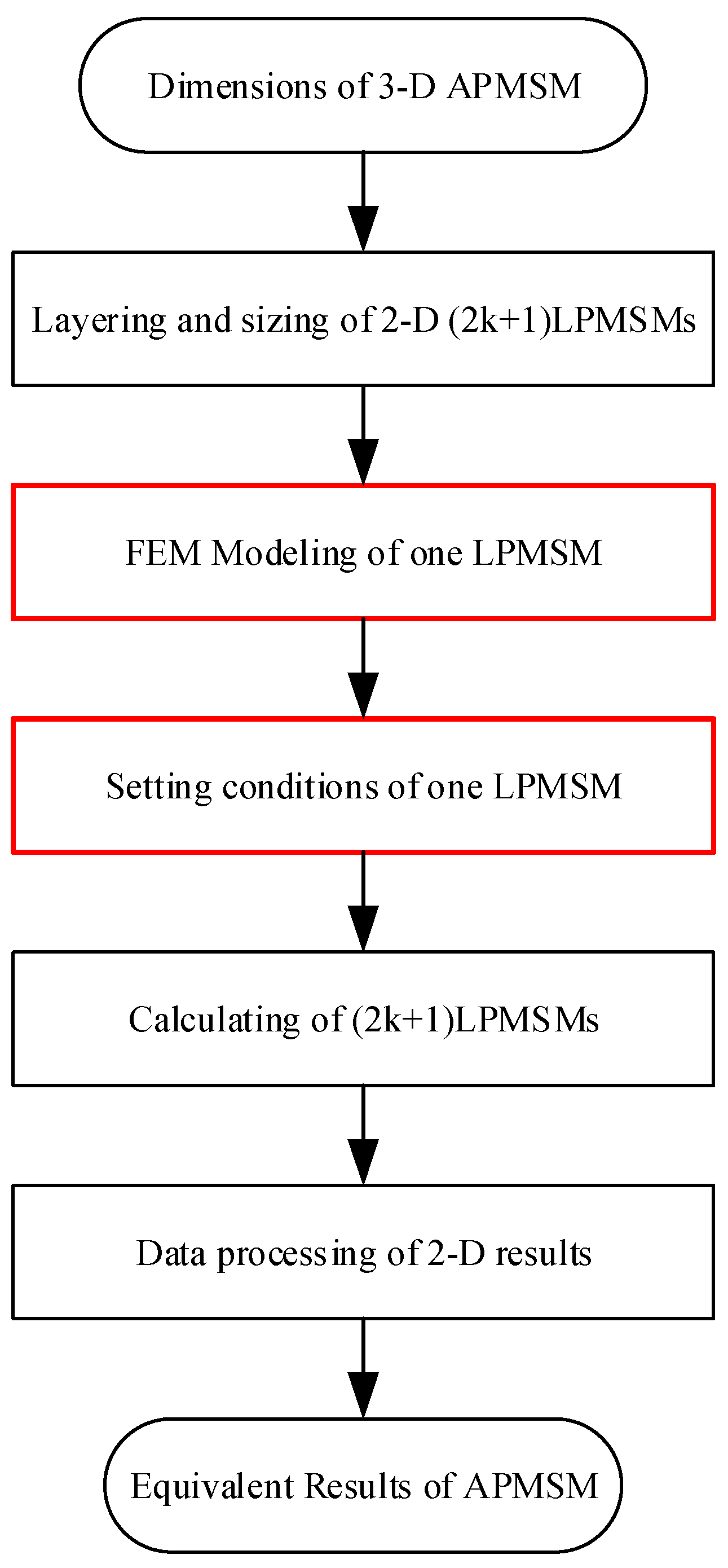
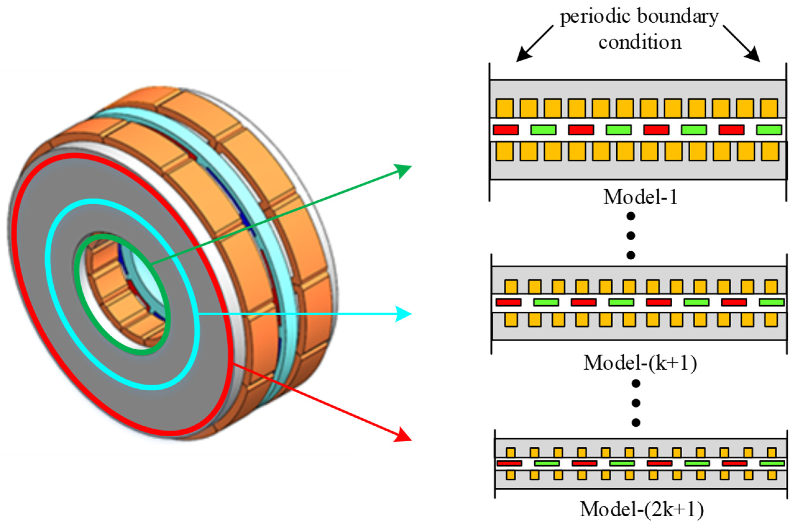
- First, divide the expected number of layers, and then calculate the average radius length and thickness of each layer of a thin circular ring;
- Then, calculate the specific parameters of the polar arc coefficient, slot width, tooth width, and slot height of the layer corresponding to its average radius;
- Afterward, an equivalent linear motor model of each layer of a thin circular ring is established in sequence, where the length of the linear motor model is consistent with the average radius circumference, and the tooth slot size of the linear motor is consistent with the previous calculation result;
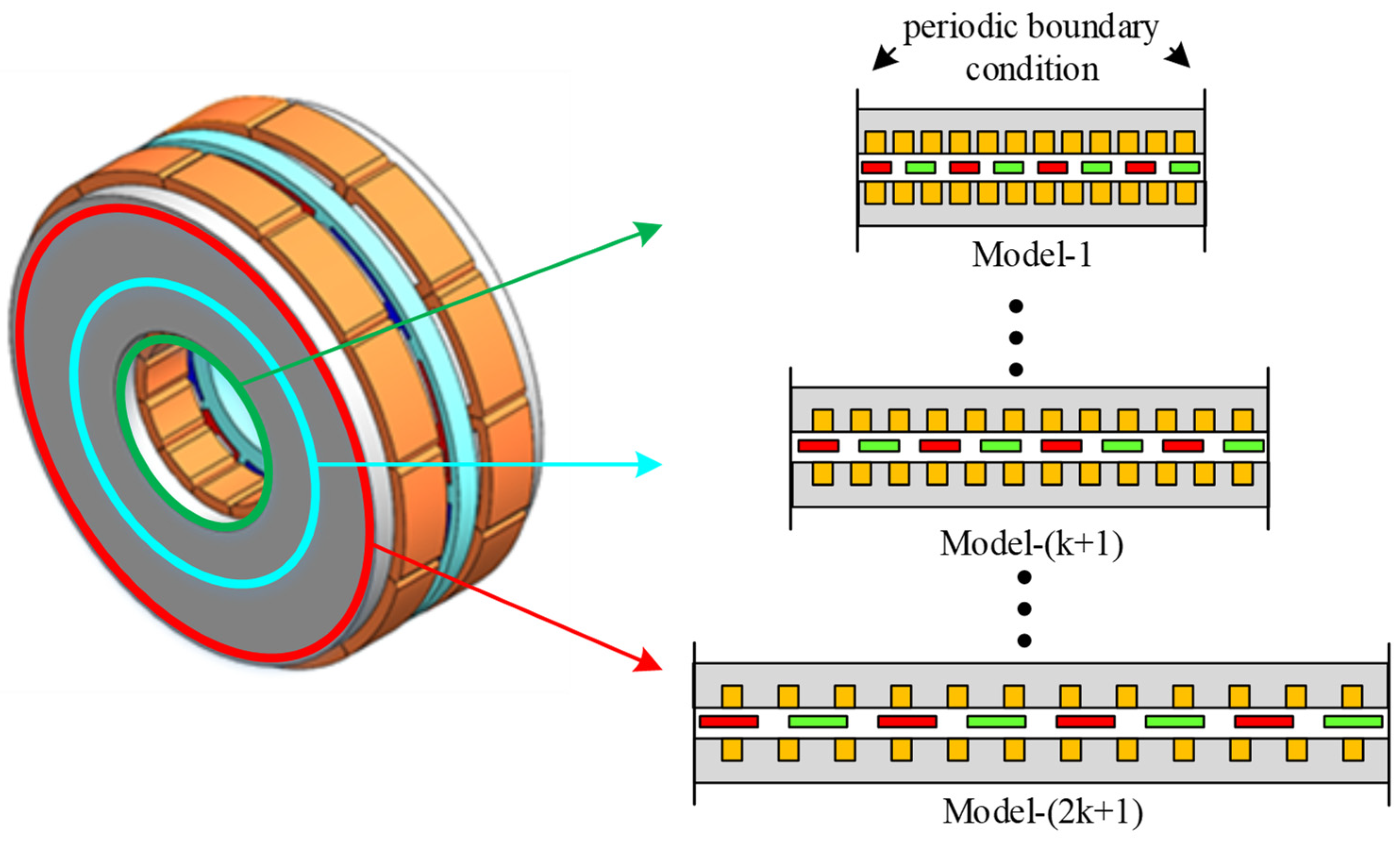
- Then, for each single-layer model, the materials and boundary conditions need to be set. It should be understood that due to the end magnetic field distortion caused by directly using an equivalent linear motor, calculation errors can be avoided. To avoid this effect, periodic boundary conditions are usually used to set the front and rear end contours of the linear motor. At this time, the linear motor is equivalent to the wireless length, which means there is no end effect;
- Next, calculate the two-dimensional electromagnetic field of the equivalent linear motor in each layer and obtain the force, magnetic linkage, back electromotive force, loss, and other data under no-load and load conditions;
- Finally, perform superposition processing to obtain the final electromagnetic calculation results of the axial flux motor.
3. Improved Equivalent Methods Based on 2D Multi-Layer Linear Permanent Magnet Synchronous Motors
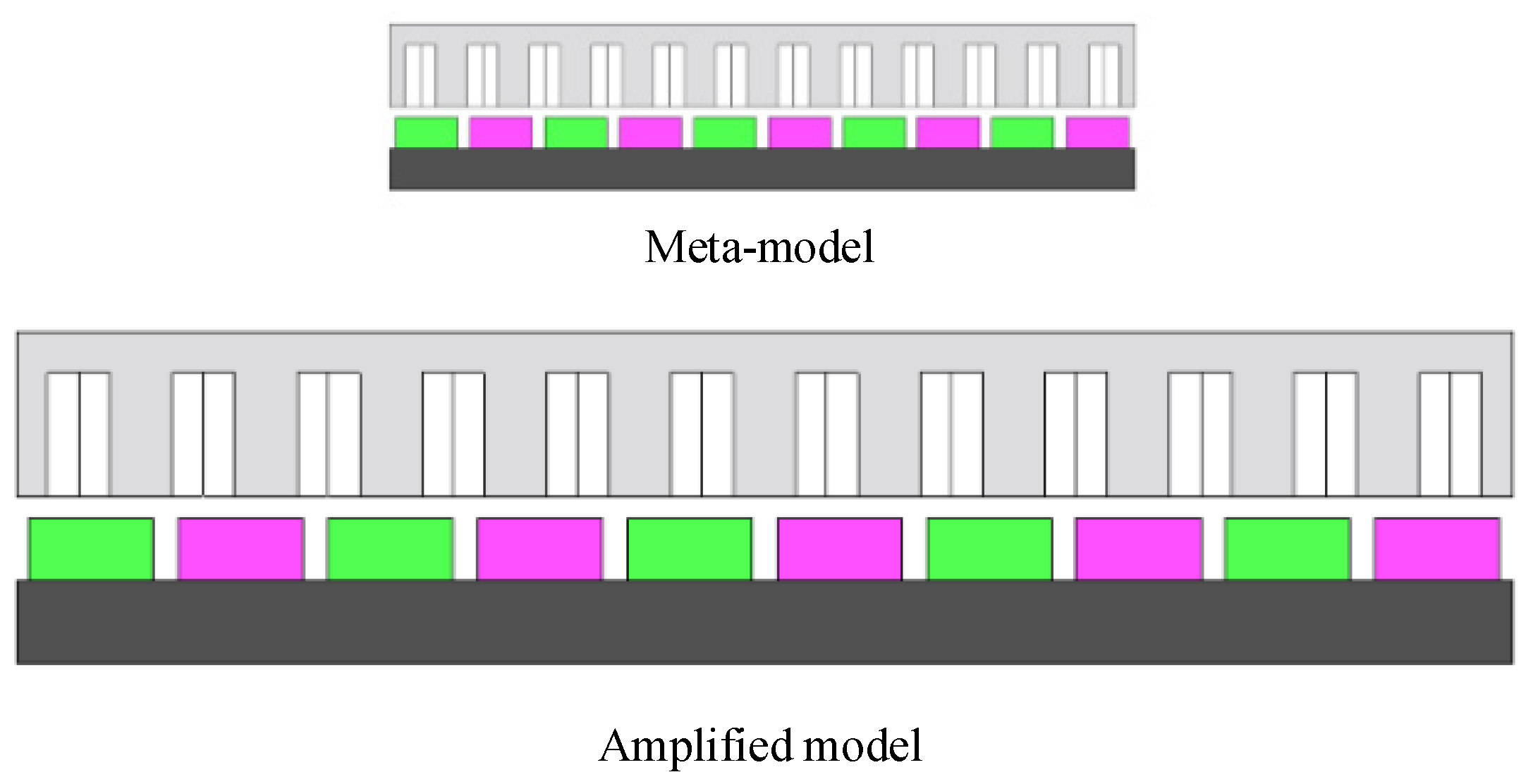
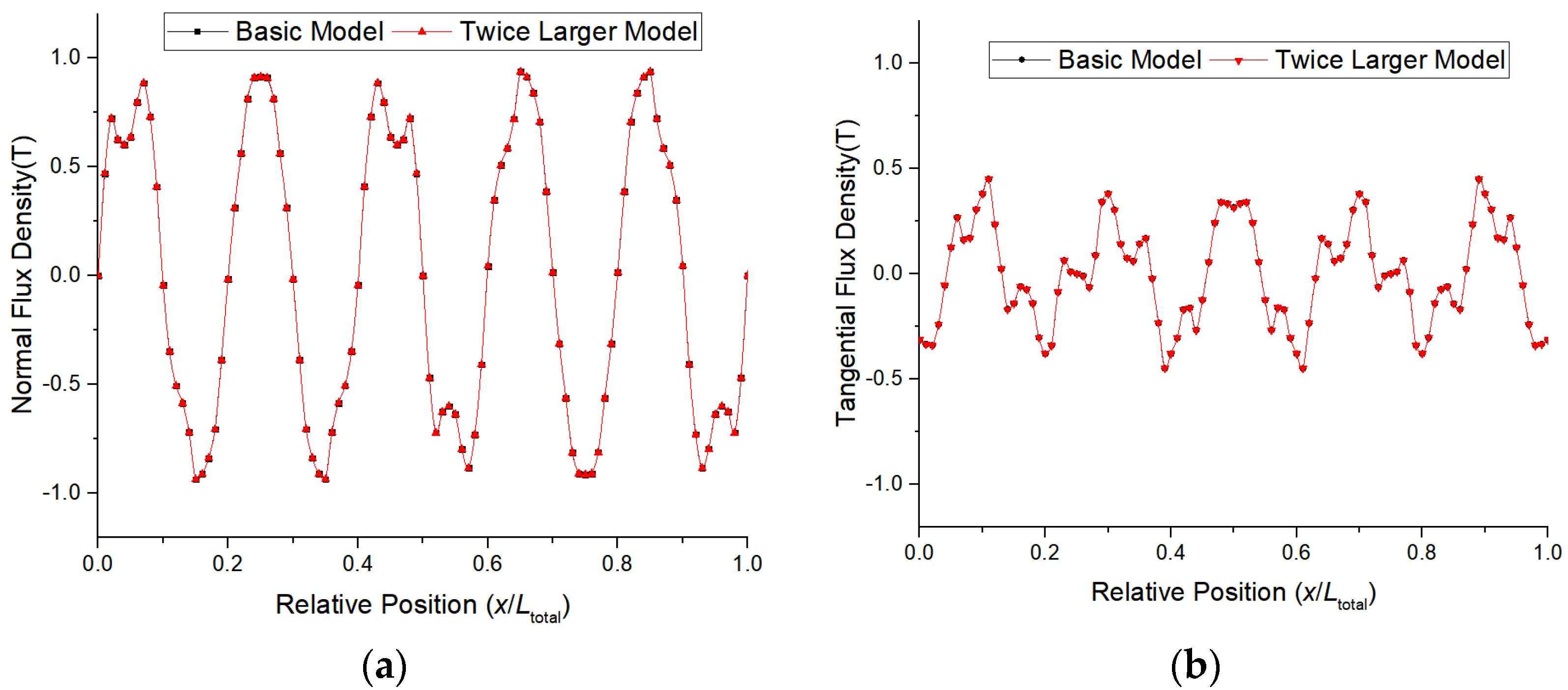
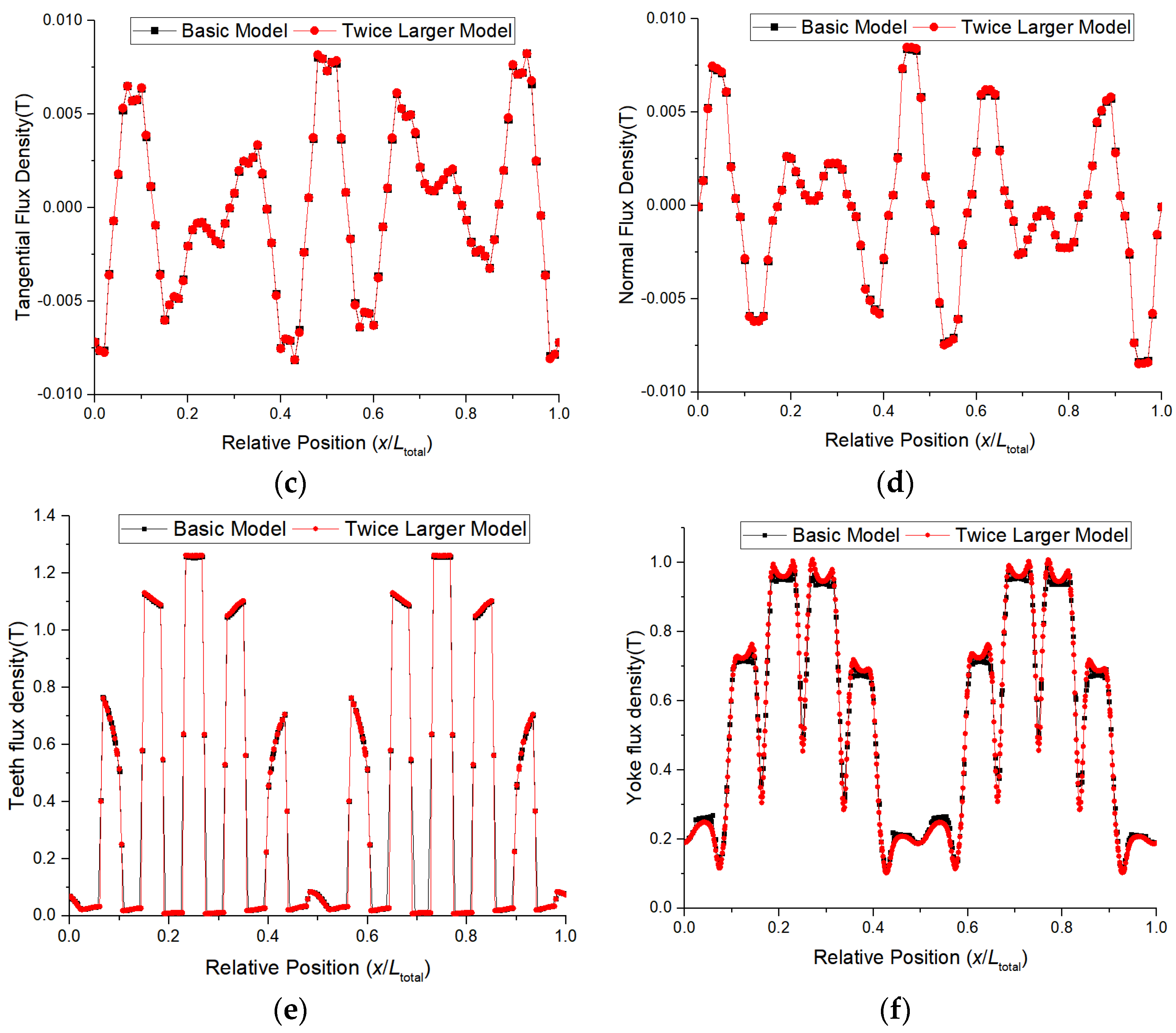
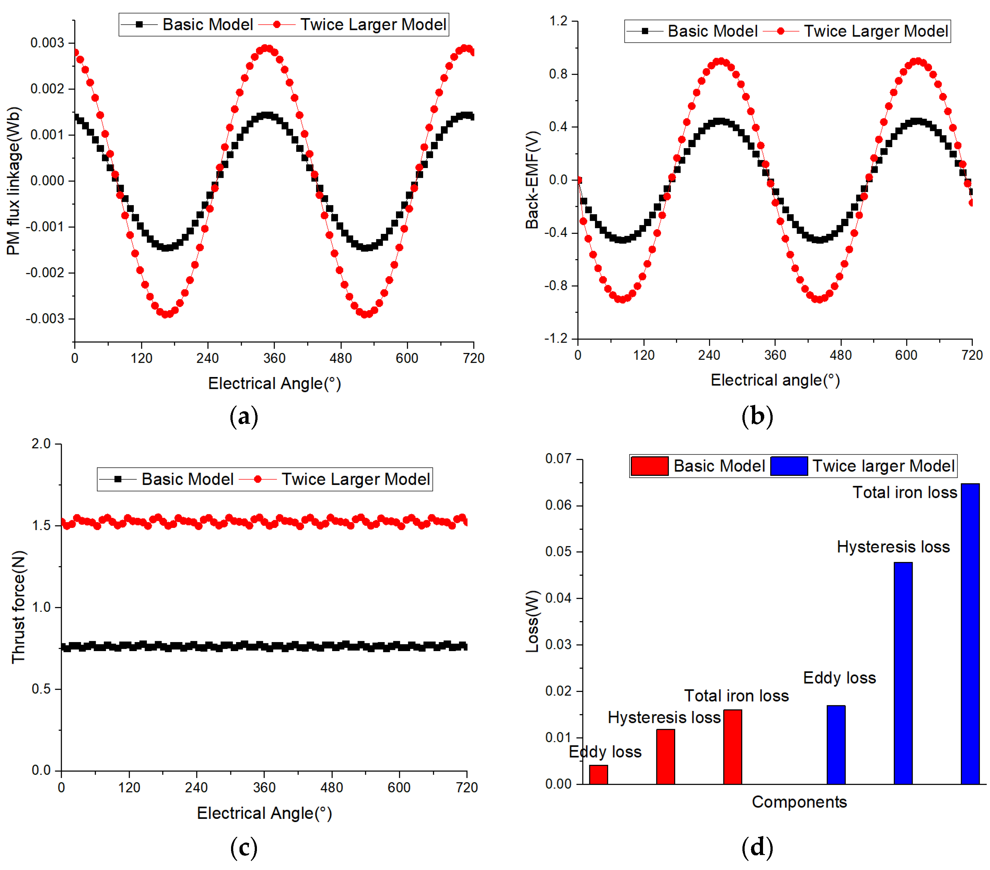
3.1. Analogy Principle of Linear Permanent Magnet Synchronous Motor Model
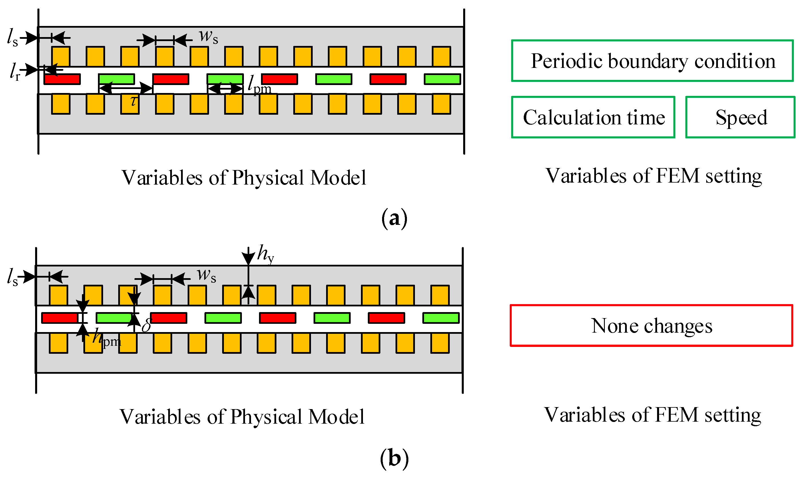
- The values of most major dimensions in the motor are proportionally amplified, including air gap length, permanent magnet thickness, permanent magnet width, pole spacing, tooth width, slot width, yoke height, and current. A small number of dimensional parameters remain unchanged, including material, pole number, slot number, and slot height.
- Set partial current, speed, and other proportional amplification while maintaining consistency in turns, frequency, and calculation steps.
3.2. Improved Equivalent Methods
- First, the expected number of layers is divided, and then the average radius length and thickness of each layer of a thin circular ring are calculated;
- Afterward, the specific parameters of the polar arc coefficient, slot width, tooth width, and slot height corresponding to the average radius of the layer are calculated and listed in the parameter table;
- Then, a two-dimensional linear motor model is established based on the parameters of the thin-layer ring in the middle of the motor, which is the overall average radius, and its materials and boundary conditions are set;
- Afterward, five parameters, namely tooth width, slot height, yoke height, permanent magnet thickness, and air gap length, are selected as variables. According to formula 11, the equivalent slot height, tooth width, air gap, and magnetic steel thickness at different radii are calculated sequentially, and they are set in the linear motor model in the previous step;
- Next, the two-dimensional electromagnetic field is calculated under different parameter conditions, and the force, magnetic linkage, back electromotive force, loss, and other data under no-load and load conditions are obtained;
- Finally, the electromagnetic calculation results of the axial flux motor are obtained by superposition processing.
4. Validation of Proposed Method
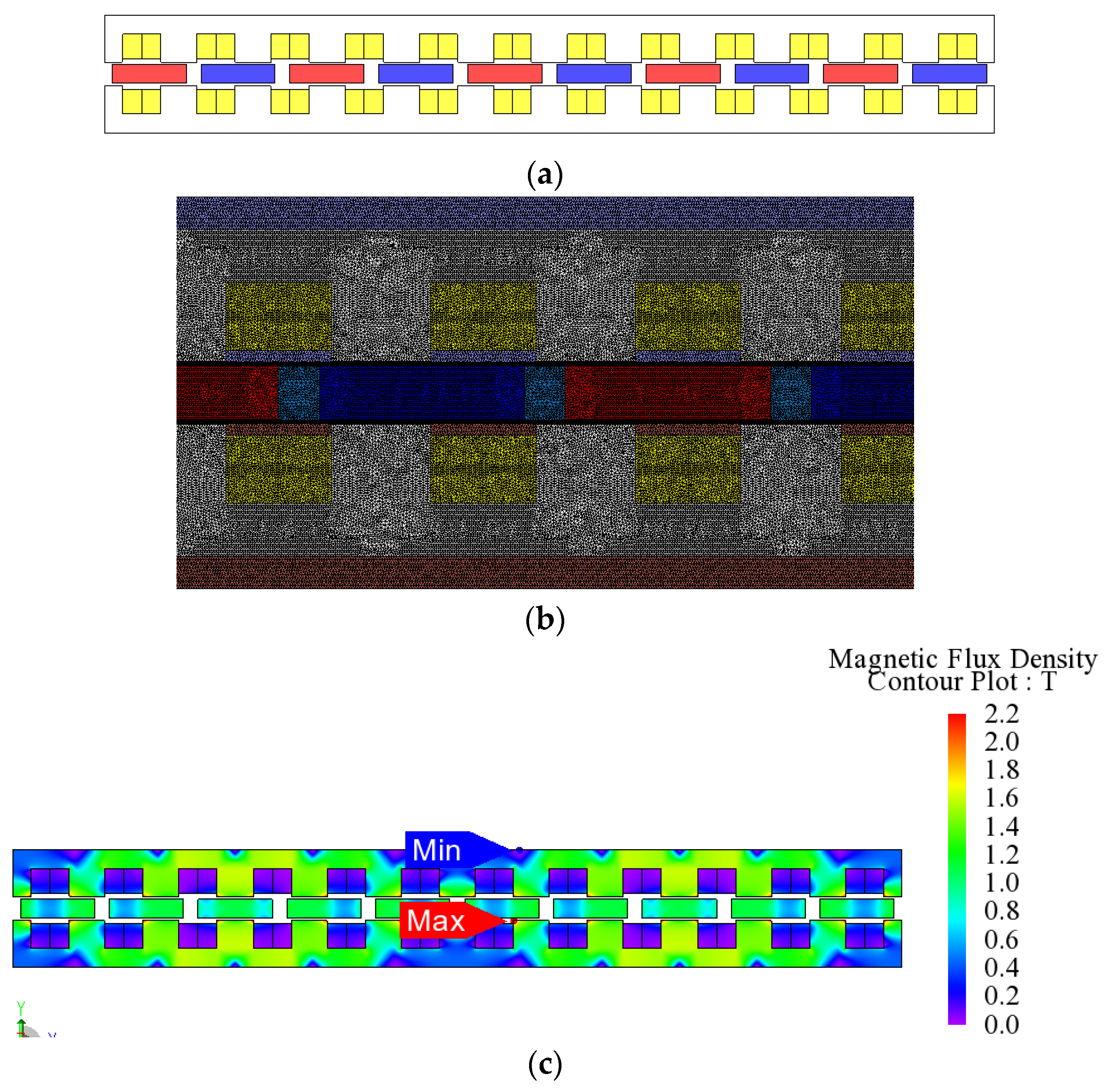
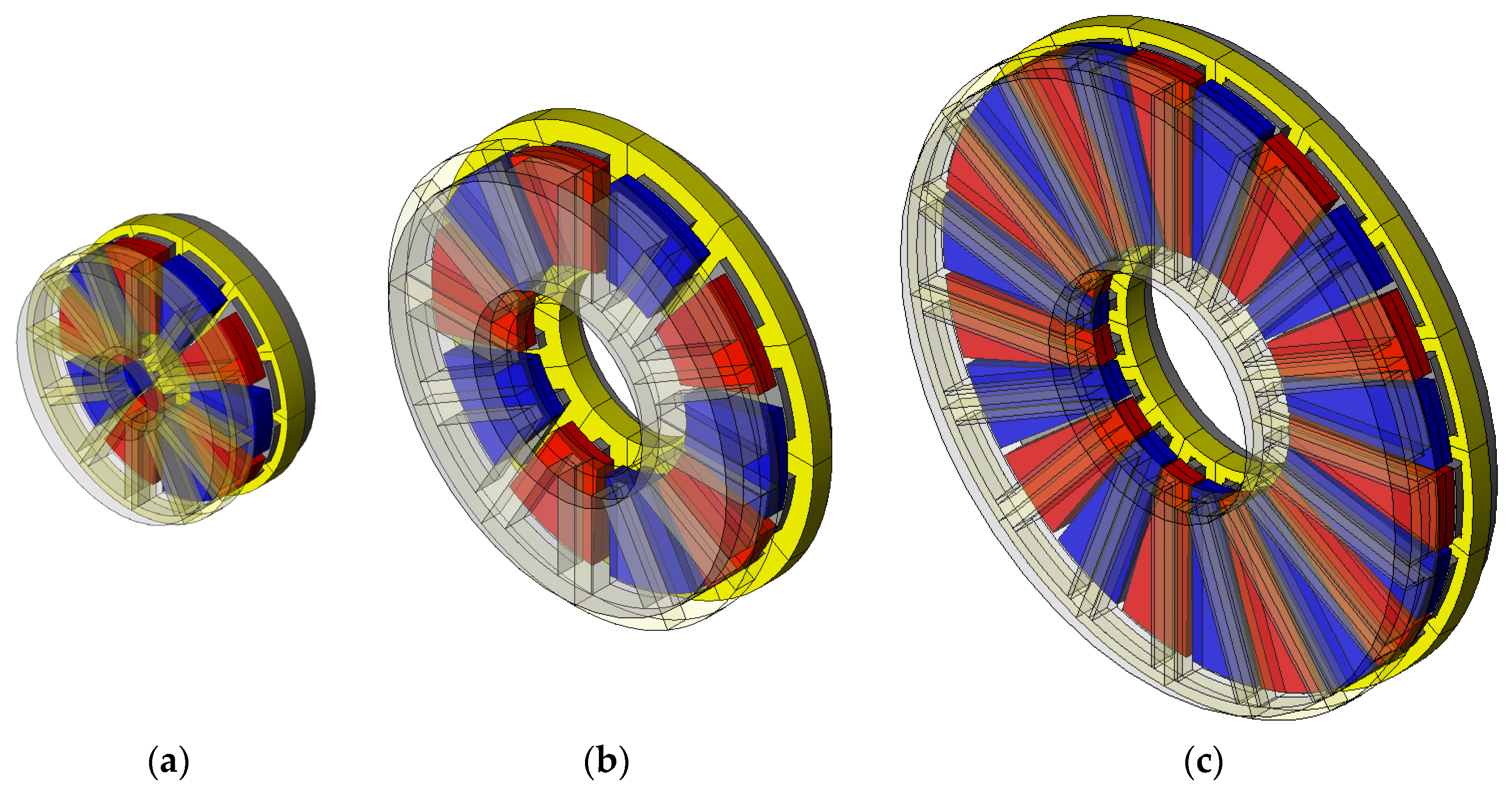
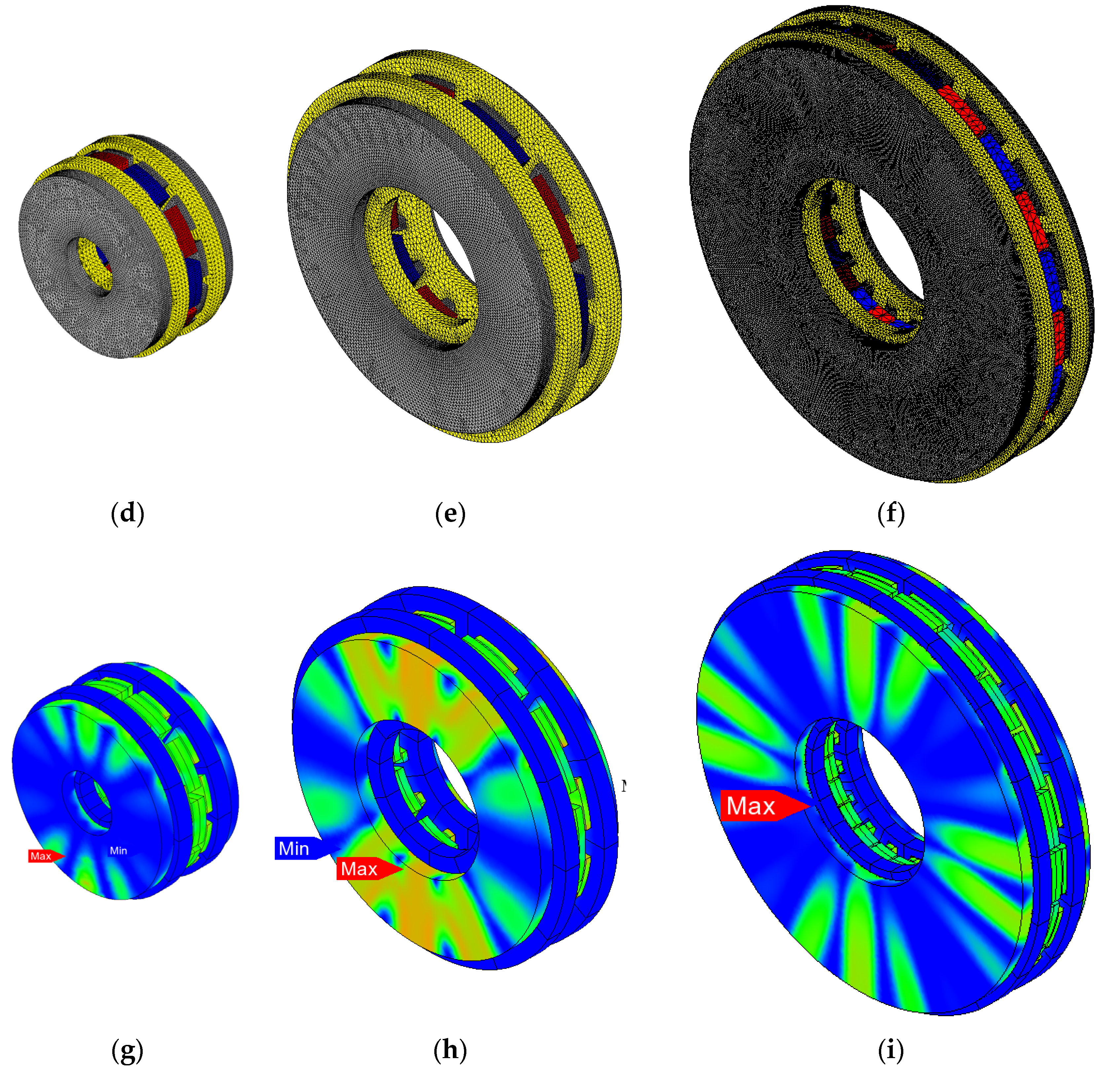
4.1. Three-Dimensional Model and Proposed Two-Dimensional Model
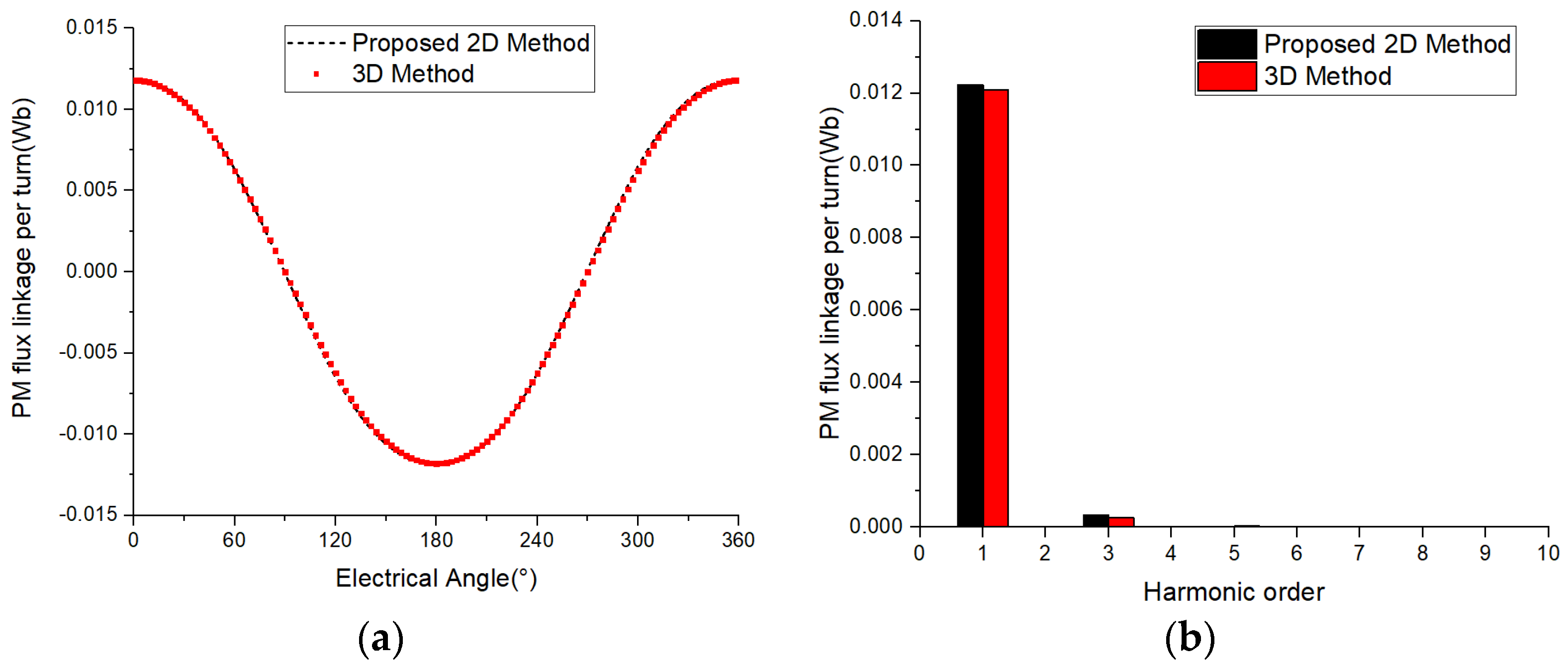
4.2. Comparison of Permanent Magnetic Flux Linkage
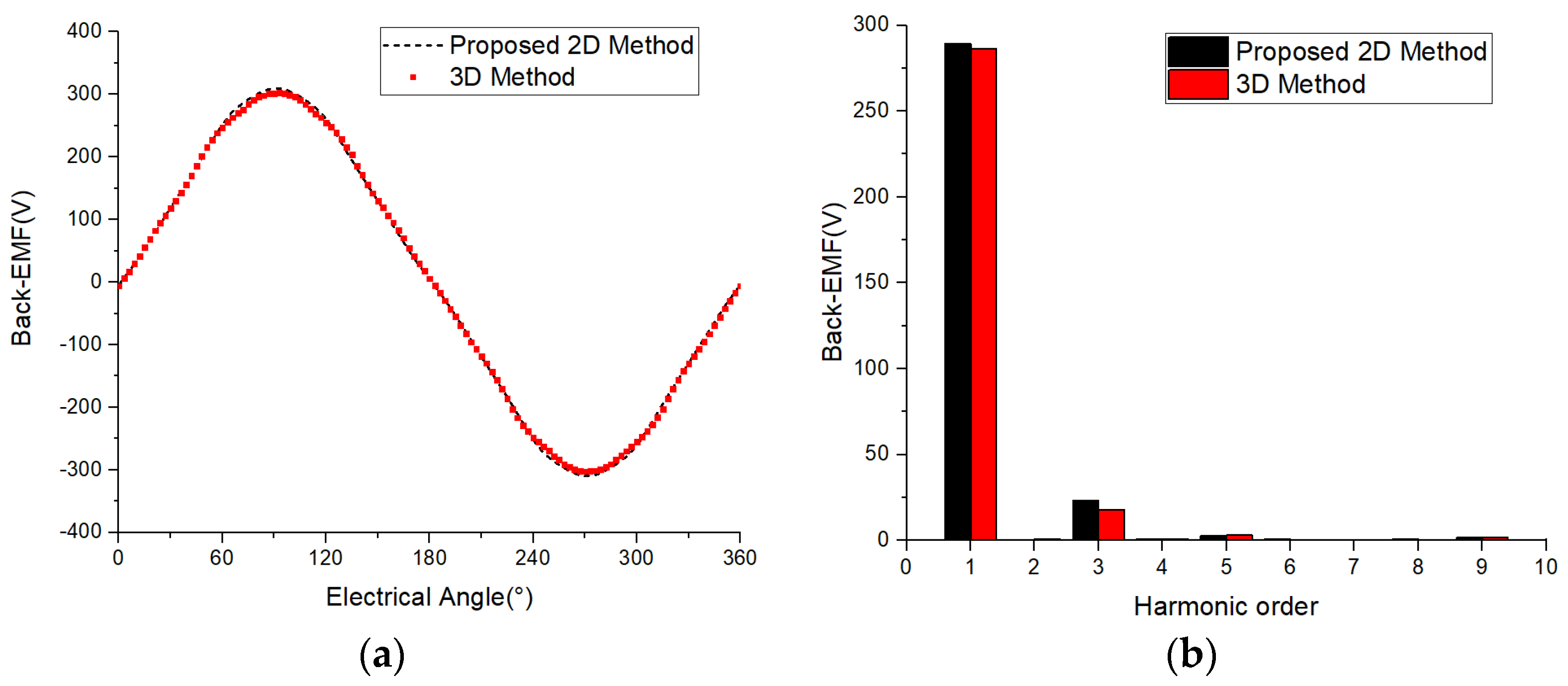
4.3. Comparison of No-Load Back Electromotive Force
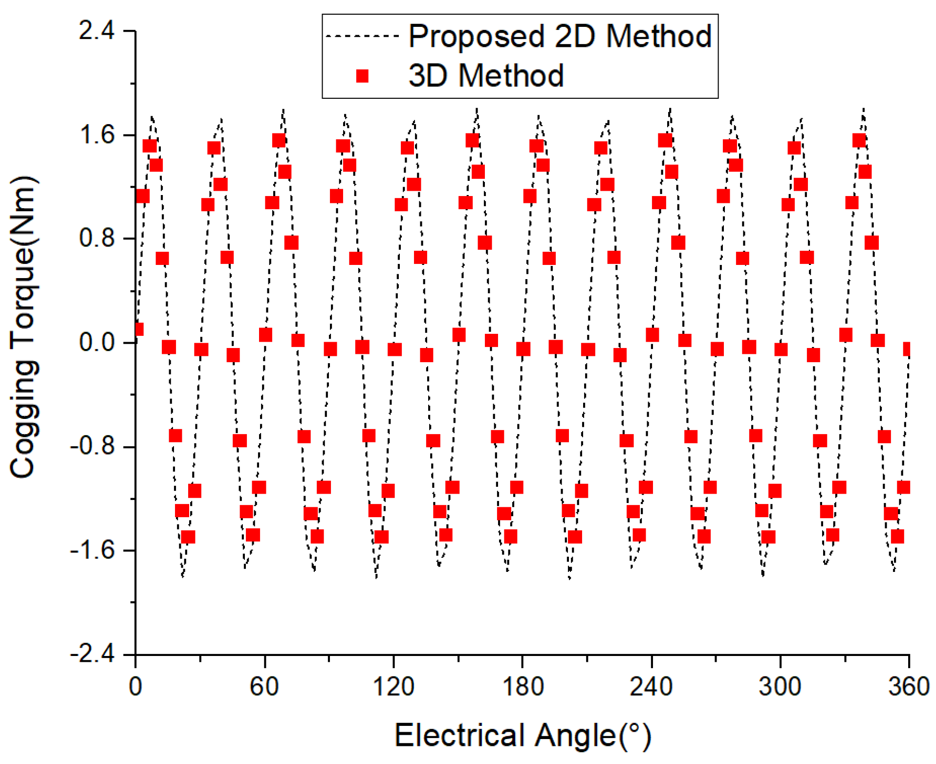
4.4. Comparison of Cogging Torque
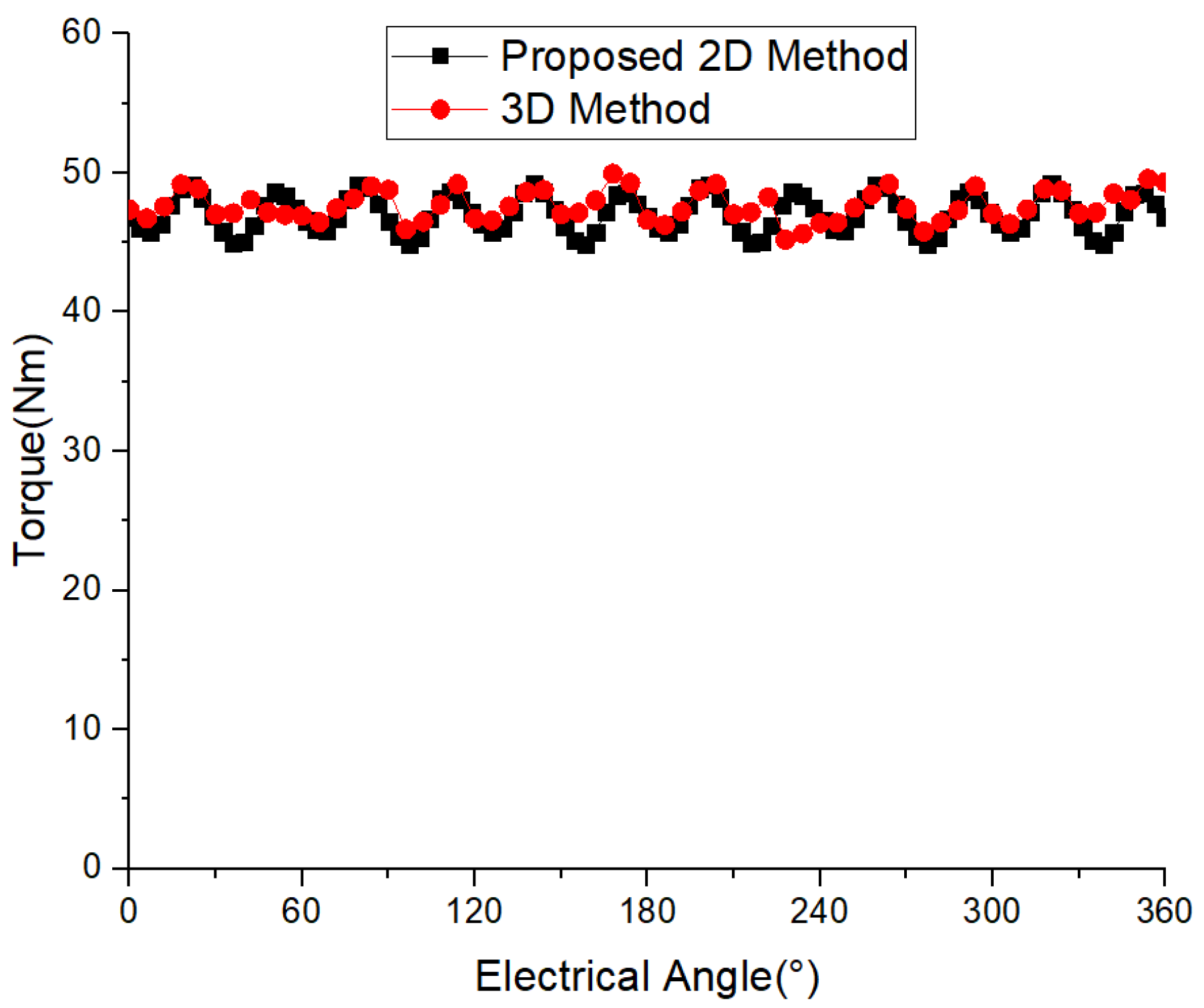
4.5. Comparison of Electromagnetic Torque
4.6. Comparison of Iron Loss
4.7. Calculation Time
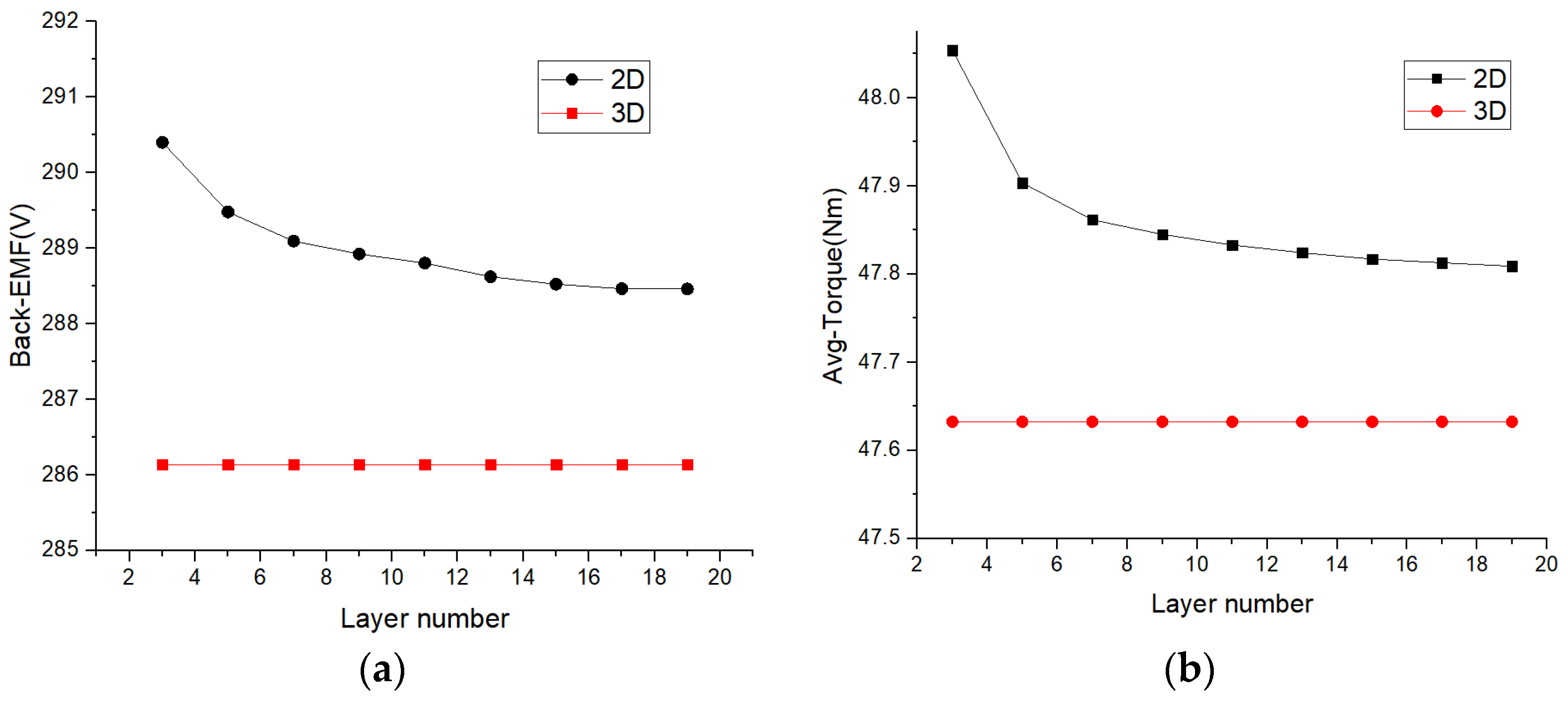
4.8. Impact of the Number of Layers on the Results
4.9. Validation of Other Random Models
5. Conclusions
Author Contributions
Funding
Institutional Review Board Statement
Informed Consent Statement
Data Availability Statement
Conflicts of Interest
References
- Tiegna, H.; Bellara, A.; Amara, Y.; Barakat, G. Analytical Modeling of the Open-Circuit Magnetic Field in Axial Flux Permanent-Magnet Machines with Semi-Closed Slots. IEEE Trans. Magn. 2012, 48, 1212–1226. [Google Scholar] [CrossRef]
- Azzouzi, J.; Barakat, G.; Dakyo, B. Quasi-3-D analytical modeling of the magnetic field of an axial flux permanent-magnet synchronous machine. IEEE Trans. Energy Convers. 2005, 20, 746–752. [Google Scholar] [CrossRef]
- Gieras, J.F.; Wang, R.J.; Kamper, M.J. Axial Flux Permanent Magnet Brushless Machines; Springer: Dordrecht, The Netherlands, 2004. [Google Scholar]
- Parviainen, A. Design of Axial-Flux Permanent-Magnet Low-Speed Machines and Performance Comparison between Radial-Flux and Axial-Flux Machines. Ph.D. Thesis, University of Technology, Lappeenranta, Finland, 2005. [Google Scholar]
- Nguyen, T.D.; Tseng, K.J.; Zhang, S.; Nguyen, H.T. A Novel Axial Flux Permanent-Magnet Machine for Flywheel Energy Storage System: Design and Analysis. IEEE Trans. Ind. Electron. 2011, 58, 3784–3794. [Google Scholar] [CrossRef]
- Liew, G.S.; Soong, W.L.; Ertugrul, N.; Gayler, J. Analysis and performance investigation of an axial-field PM motor utilising cut amorphous magnetic material. In Proceedings of the 2010 20th Australasian Universities Power Engineering Conference, Christchurch, New Zealand, 5–8 December 2010. [Google Scholar]
- Kumar, S.; Lipo, T.A.; Kwon, B.I. A 32 000 r/min Axial Flux Permanent Magnet Machine for Energy Storage with Mechanical Stress Analysis. IEEE Trans. Magn. 2016, 52, 1–4. [Google Scholar] [CrossRef]
- Andriollo, M.; Graziottin, F.; Tortella, A. Design of an Axial-Type Magnetic Gear for the Contact-Less Recharging of a Heavy-Duty Bus Flywheel Storage System. IEEE Trans. Ind. Appl. 2017, 53, 3476–3484. [Google Scholar] [CrossRef]
- Chen, Q.; Liang, D.; Jia, S.; Ze, Q.; Liu, Y. Analysis of Winding MMF and Loss for Axial Flux PMSM with FSCW Layout and YASA Topology. IEEE Trans. Ind. Appl. 2020, 56, 2622–2635. [Google Scholar] [CrossRef]
- Liu, Y.; Zhang, Z.; Wang, C.; Geng, W.; Yang, T. Design and analysis of oil-immersed cooling stator with nonoverlapping concentrated winding for high-power ironless stator axial-flux permanent magnet machines. IEEE Trans. Ind. Electron. 2021, 68, 2876–2886. [Google Scholar] [CrossRef]
- Huang, Y.; Zhou, T.; Dong, J.; Lin, H. Magnetic Equivalent Circuit Modeling of Yokeless Axial Flux Permanent Magnet Machine with Segmented Armature. IEEE Trans. Magn. 2014, 50, 1–4. [Google Scholar] [CrossRef]
- Zarko, D.; Ban, D.; Lipo, T.A. Analytical Solution for Cogging Torque in Surface Permanent-Magnet Motors Using Conformal Mapping. IEEE Trans. Magn. 2007, 44, 52–65. [Google Scholar] [CrossRef]
- Driscoll, T.A.; Trefethen, L.N. Schwarz-Christoffel Mapping; Cambridge University Press: Cambridge, UK, 2002. [Google Scholar]
- Zhu, Z.Q.; Wu, L.J.; Xia, Z.P. An Accurate Subdomain Model for Magnetic Field Computation in Slotted Surface-Mounted Permanent-Magnet Machines. IEEE Trans. Magn. 2010, 46, 1100–1115. [Google Scholar] [CrossRef]
- Yan, B.; Li, X.; Wang, X.; Yang, Y.; Chen, D. Magnetic Field Prediction for Line-Start Permanent Magnet Synchronous Motor via Incorporating Geometry Approximation and Finite Difference Method into Subdomain Model. IEEE Trans. Ind. Electron. 2023, 70, 2843–2854. [Google Scholar] [CrossRef]
- Ni, Y.; Jiang, X.; Xiao, B.; Wang, Q. Analytical modeling and optimization of dual-layer segmented Halbach permanent-magnet machines. IEEE Trans. Magn. 2020, 56, 8100811. [Google Scholar] [CrossRef]

| Size Parameter | Parameter Value |
|---|---|
| Inner radius of stator core (mm) | 50 |
| Outer radius of stator core (mm) | 100 |
| Permanent magnet thickness (mm) | 10 |
| Air gap length (mm) | 1 |
| Width of stator slot (mm) | 20 |
| Stator slot depth (mm) | 15 |
| Single stator axial length (mm) | 25 |
| Permanent magnet material | NdFeB42 |
| Number of turns (turns) | 76 |
| Rated speed (r/min) | 600 |
| Polar arc coefficient | 0.83 |
| Number of poles | 10 |
| Number of slots | 12 |
| Inner radius of permanent magnet (mm) | 50 |
| Layered Serial Number | Average Radius | Scaling Coefficient |
|---|---|---|
| 1st | 52.77778 | 0.7037 |
| 2nd | 58.33333 | 0.77778 |
| 3rd | 63.88889 | 0.85185 |
| 4th | 69.44444 | 0.92593 |
| 5th | 75 | 1 |
| 6th | 80.55556 | 1.07407 |
| 7th | 86.11111 | 1.14815 |
| 8th | 91.66667 | 1.22222 |
| 9th | 97.22222 | 1.2963 |
| Time-Consuming | Unit | 3D FEM | Existed 2D FEM | Proposed 2D FEM |
|---|---|---|---|---|
| Geometric modeling | min | 15 | 5 × 9 = 45 | 5 |
| Simulation settings | min | 3 | 3 × 9 = 45 | 3 |
| Solution time | min | 6000 | 20 × 9 = 180 | 20 × 9 = 180 |
| Result processing time | min | 3 | 10 | 10 |
| Total time | min | 6021 | 280 | 198 |
| 3-Layer | 5-Layer | 7-Layer | 9-Layer | 11-Layer | 13-Layer | 15-Layer | 17-Layer | 19-Layer | |
|---|---|---|---|---|---|---|---|---|---|
| 1st | 58.33333 | 55 | 53.57143 | 52.77778 | 52.27273 | 51.92308 | 51.66667 | 51.47059 | 51.31579 |
| 2nd | 75 | 65 | 60.71429 | 58.33333 | 56.81818 | 55.76923 | 55 | 54.41176 | 53.94737 |
| 3rd | 91.66667 | 75 | 67.85714 | 63.88889 | 61.36364 | 59.61538 | 58.33333 | 57.35294 | 56.57895 |
| 4th | 85 | 75 | 69.44444 | 65.90909 | 63.46154 | 61.66667 | 60.29412 | 59.21053 | |
| 5th | 95 | 82.14286 | 75 | 70.45455 | 67.30769 | 65 | 63.23529 | 61.84211 | |
| 6th | 89.28571 | 80.55556 | 75 | 71.15385 | 68.33333 | 66.17647 | 64.47368 | ||
| 7th | 96.42857 | 86.11111 | 79.54545 | 75 | 71.66667 | 69.11765 | 67.10526 | ||
| 8th | 91.66667 | 84.09091 | 78.84615 | 75 | 72.05882 | 69.73684 | |||
| 9th | 97.22222 | 88.63636 | 82.69231 | 78.33333 | 75 | 72.36842 | |||
| 10th | 93.18182 | 86.53846 | 81.66667 | 77.94118 | 75 | ||||
| 11th | 97.72727 | 90.38462 | 85 | 80.88235 | 77.63158 | ||||
| 12th | 94.23077 | 88.33333 | 83.82353 | 80.26316 | |||||
| 13th | 98.07692 | 91.66667 | 86.76471 | 82.89474 | |||||
| 14th | 95 | 89.70588 | 85.52632 | ||||||
| 15th | 98.33333 | 92.64706 | 88.15789 | ||||||
| 16th | 95.58824 | 90.78947 | |||||||
| 17th | 98.52941 | 93.42105 | |||||||
| 18th | 96.05263 | ||||||||
| 19th | 98.68421 |
| Parameter | Unit | Model-1 | Model-2 (Foregoing Analyzed One) | Model-3 |
|---|---|---|---|---|
| Inner radius | mm | 20 | 50 | 60 |
| Outer radius | mm | 60 | 100 | 150 |
| Single Stator axial length | mm | 27 | 25 | 20 |
| Rated speed | r/min | 2400 | 600 | 1500 |
| Polar arc coefficient | -- | 0.80 | 0.83 | 0.92 |
| Number of poles | -- | 10 | 10 | 22 |
| Number of slots | -- | 12 | 12 | 18 |
| Width of stator slot | mm | 8 | 20 | 16 |
| Stator slot depth | mm | 17 | 15 | 12 |
| Fundamental amplitudes of Back-EMF 3D | V | 113.52 | 286.14 | 285.32 |
| Fundamental amplitudes of Back-EMF 2D | V | 114.17 | 289.08 | 289.77 |
| error | % | 0.57 | 1.01 | 1.53 |
| Average torque 3D | N.m | 10.76 | 47.63 | 105.71 |
| Average torque 2D | N.m | 10.85 | 47.85 | 107.41 |
| error | % | 0.83 | 1.21 | 1.58 |
| Core loss 3D | W | 83.57 | 31.69 | 705.74 |
| Core loss 2D | W | 82.34 | 31.19 | 696.48 |
| error | % | 1.47 | 1.57 | 1.33 |
Disclaimer/Publisher’s Note: The statements, opinions and data contained in all publications are solely those of the individual author(s) and contributor(s) and not of MDPI and/or the editor(s). MDPI and/or the editor(s) disclaim responsibility for any injury to people or property resulting from any ideas, methods, instructions or products referred to in the content. |
© 2023 by the authors. Licensee MDPI, Basel, Switzerland. This article is an open access article distributed under the terms and conditions of the Creative Commons Attribution (CC BY) license (https://creativecommons.org/licenses/by/4.0/).
Share and Cite
Wu, H.; Zhou, Y.; Yang, X. An Improved Two-Dimensional Simplification Calculation Method for Axial Flux Permanent Magnet Synchronous Motor. Appl. Sci. 2023, 13, 11748. https://doi.org/10.3390/app132111748
Wu H, Zhou Y, Yang X. An Improved Two-Dimensional Simplification Calculation Method for Axial Flux Permanent Magnet Synchronous Motor. Applied Sciences. 2023; 13(21):11748. https://doi.org/10.3390/app132111748
Chicago/Turabian StyleWu, Hongxue, Yiheng Zhou, and Xiaobao Yang. 2023. "An Improved Two-Dimensional Simplification Calculation Method for Axial Flux Permanent Magnet Synchronous Motor" Applied Sciences 13, no. 21: 11748. https://doi.org/10.3390/app132111748
APA StyleWu, H., Zhou, Y., & Yang, X. (2023). An Improved Two-Dimensional Simplification Calculation Method for Axial Flux Permanent Magnet Synchronous Motor. Applied Sciences, 13(21), 11748. https://doi.org/10.3390/app132111748