Abstract
Metamaterial-based quarter-wave plates (QWPs) have emerged as promising candidates for advanced polarization control in a variety of optical applications, owing to their unique properties, such as ultra-thin profiles and tailored spectral responses. We design an ultra-thin, high-efficiency, and broadband QWP in transmission mode based on a TiO/Au grating structure. We show that multiple reflections and the near-field effects associated with the integration of these devices pose challenges that must be considered when combining multiple metamaterials. We present insights that facilitate improved design methodology and the optimization of integrated metamaterial QWPs and other metadevices. Our results contribute to the development of miniaturized and high-density advanced lightwave and polarization control devices in optical systems.
1. Introduction
The polarization degree of freedom has played a critical role in advanced sciences and technologies [1] involving weak to strong intensities of light. Recent research that considers the light polarization includes high-efficiency polarization locking [2], generalized polarization transformations [1], full-Stokes polarization perfect absorption [3], frequency tunable polarization conversion [4], and enhanced broadband nonlinear optical processes [5], to name a few. Metamaterials have garnered significant interest in the field due to their extraordinary properties and versatile applications, which stem from their ability to manipulate light in ways that are unattainable with conventional materials [6,7]. One metamaterial-based optical device is the quarter-wave plate (QWP), which is an indispensable tool for polarization control and manipulation [8,9,10]. QWPs work by introducing a phase shift between the orthogonal components of an incident lightwave, effectively transforming linearly polarized light into circularly polarized light or vice versa.
Recent advances in nanofabrication techniques and material science have enabled the construction of innovative metamaterial-based optical devices [11,12]. This progress has given rise to the design and fabrication of ultra-thin, sub-wavelength QWPs [13,14,15,16,17,18], emphasizing the ongoing trend towards device miniaturization and integration [19,20,21,22,23,24,25,26,27,28,29,30,31,32]. Such miniaturization and incorporation of metamaterials present exciting prospects in classical and quantum optical information systems (e.g., imaging, sensing, communications, and cryptography). This is made possible by the extensive degrees of freedom that metamaterials provide [26,27,28,29,30,31,33,34,35,36].
As the integration of metamaterials into optical systems undergoes size reductions and neighboring structures approach the near-field region, their interaction with electromagnetic fields becomes increasingly intricate. Controlling near-field interactions within the unit cells has enabled novel metamaterials and optical phenomena, such as classical analog of electromagnetically induced transparency [37], coupled plasmonic metamaterials [38], and, more recently, chiral perfect absorbers with strong near-field enhancement [3]. While metamaterials are recognized for their inherent near-field effects [39,40,41,42,43,44,45,46,47], the precise extent of this effective region and its consequential impact on adjacent structures remain a less explored domain. Unless accounted for within a metadevice, coupling among neighboring metamaterials or optical components can trigger unwanted energy transfer. Thus, to better understand the consequences of cascading metamaterials for future integration, a comprehensive analysis of how near-field effects [26,27,28,48,49] and multiple reflections [50,51] affect the performance of the metamaterial is essential. This will ensure appropriate integration into optical designs and to understand potential complications arising from multiple reflections between devices.
To understand some of the complications when integrating metamaterials into a single device, we present an analysis of a grating structure design for a metamaterial QWP, defining its effective length due to near-field effects and its performance in a cascaded system.
The paper is organized as follows. In Section 2, we provide an overview of the theoretical framework utilized to design a grating structure-based QWP. We discuss the principles of birefringence in the context of grating structures and outline the key considerations for designing our metamaterial QWP. Furthermore, we introduce a specific design, detailing the materials and parameters employed. Then, we present the simulation results obtained using COMSOL Multiphysics software and analyze the performance of the designed grating structure as a QWP. In Section 3, we analyze the near-field performance of the grating structure, highlighting the effective length required for QWP operation. Then, we demonstrate how cascading these structures can give rise to multiple reflections, which necessitate careful consideration during the design process. The impact of these near-field effects and multiple reflections on the overall performance of the optical system is analyzed. Our analyses provide insights for multilayer metamaterial and metaoptic [26,27,28,29,30,31,32] designs toward not only better integration into optical devices but also intriguing optical phenomena [52] emerging from such integrations.
2. QWP Design and Analysis
The ability of a QWP hinges on its capacity to induce an exact phase shift, which is contingent on the birefringence of the structure. Grating structures have been extensively studied in the literature [53,54,55,56,57]. Building upon this, we design a grating-based QWP. Given that our grating structure is translationally invariant along the Y direction, we utilize 2D simulations for our analysis. In grating-based metamaterials, birefringence originates from the anisotropic optical response, which is induced by the orientation of the layers in the grating structure [54,58].
To determine a starting point for the frequency domain solver in the COMSOL simulations (Figure 1), we employed the Maxwell–Garnett equations, which have been demonstrated to effectively characterize grating structures [26,53]. The equations using the coordinate system shown in Figure 1 are as follows:
where and are the relative permittivities of the metal and dielectric materials, respectively, and and denote the heights of the respective metal and dielectric materials within the unit cell. The use of and was due to the X propagating wave and the orientation of the layers as shown in Figure 1.
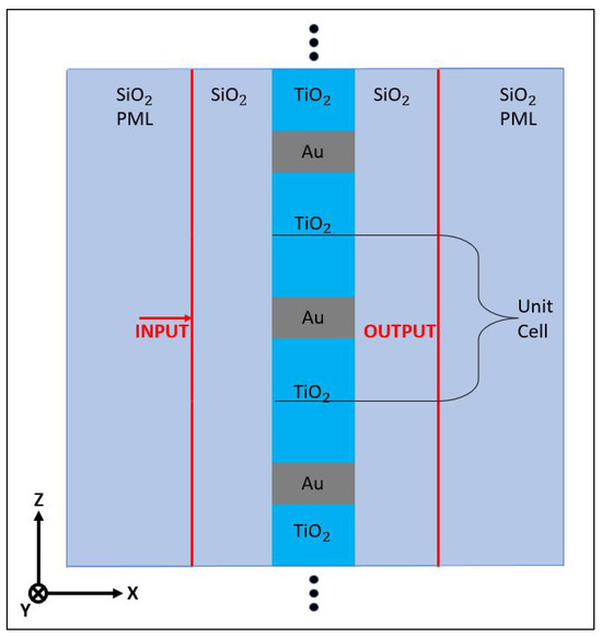
Figure 1.
The 2D design with the grating structure embedded in silicon dioxide. In the simulation, periodic boundaries are implemented at the top and bottom, while scattering boundaries are established on the left and right sides. Perfectly matched layers (PMLs) are positioned before the input and after the output to effectively mitigate any boundary-induced reflections that could compromise the data collection. The input is 150 nm before the grating and the output is located at 150 nm from the back side of the grating. The unit cell is 175 nm in the Z direction, with the gold taking 50 nm of the unit cell, and the titanium dioxide occupies the remaining 125 nm. The grating is 100 nm wide in the X direction.
In order to effectively assess a cascaded metamaterial system, our primary objective is to design a transmission-based QWP having a bandwidth centered around an 800 nm wavelength [59], optimized for a normally incident uniform plane wave. The transmission-based design along with the normally incident plane wave will allow for a seamless integration of the structure into a cascaded system. To achieve better agreement with the Maxwell–Garnet equation, the unit cell and feature sizes are minimized while staying within the practical limitations of contemporary fabrication techniques [56,60,61,62,63,64]. We do not exceed a depth-to-height ratio of 2:1, and the minimum feature height is set to 50 nm. Using the Maxwell–Garnett equations as a starting point and using COMSOL to finalize the design give the finalized grating a depth of 100 nm and a metal height of 50 nm. In the selection of materials, gold and silver emerge as strong candidates due to their advantageous permittivities (i.e., relatively low losses) at the desired 800 nm wavelength. However, the inclination of silver to oxidize led us to choose gold [65] as a more stable option. For the dielectric material, titanium dioxide [56] was selected. The grating structure is embedded in silicon dioxide [66]. We incorporated the relative electric permittivities of the chosen materials as given in Table 1. The design culminates in the configuration depicted in Figure 1 with a total unit cell height of 175 nm. Of this, 50 nm is occupied by gold, with the remaining 125 nm being titanium dioxide.

Table 1.
Complex relative electric permittivities () of SiO, TiO, and Au at the simulation wavelength limits and the targeted wavelength of 800 nm. The associated references detail the full material parameters employed throughout the wavelength sweeps in the simulations.
In order to effectively evaluate the performance of the proposed QWP design, we employ the Stokes parameters. These parameters provide a comprehensive characterization of our electromagnetic field propagating in the X-direction, taking into account the phase difference, , between the two orthogonal field components. They are given as [50,67,68,69]
where is the j′th component of the electric field, and we use convention consistent with COMSOL.
The Stokes parameters allow us to discern the proficiency of QWP in transforming linearly polarized light into circularly polarized light. One of the vital metrics for this characterization is ellipticity (), defined as [69]
The ellipticity metric provides an understanding of the degree of circularity in the wave polarization, with 1 representing a perfect left-handed circular polarization, −1 indicating a perfect right-handed circular polarization, and zero denoting a linear polarization. For our grating structure, we assume it performs an appropriate QWP operation if at the output is greater than 0.99 [69,70,71].
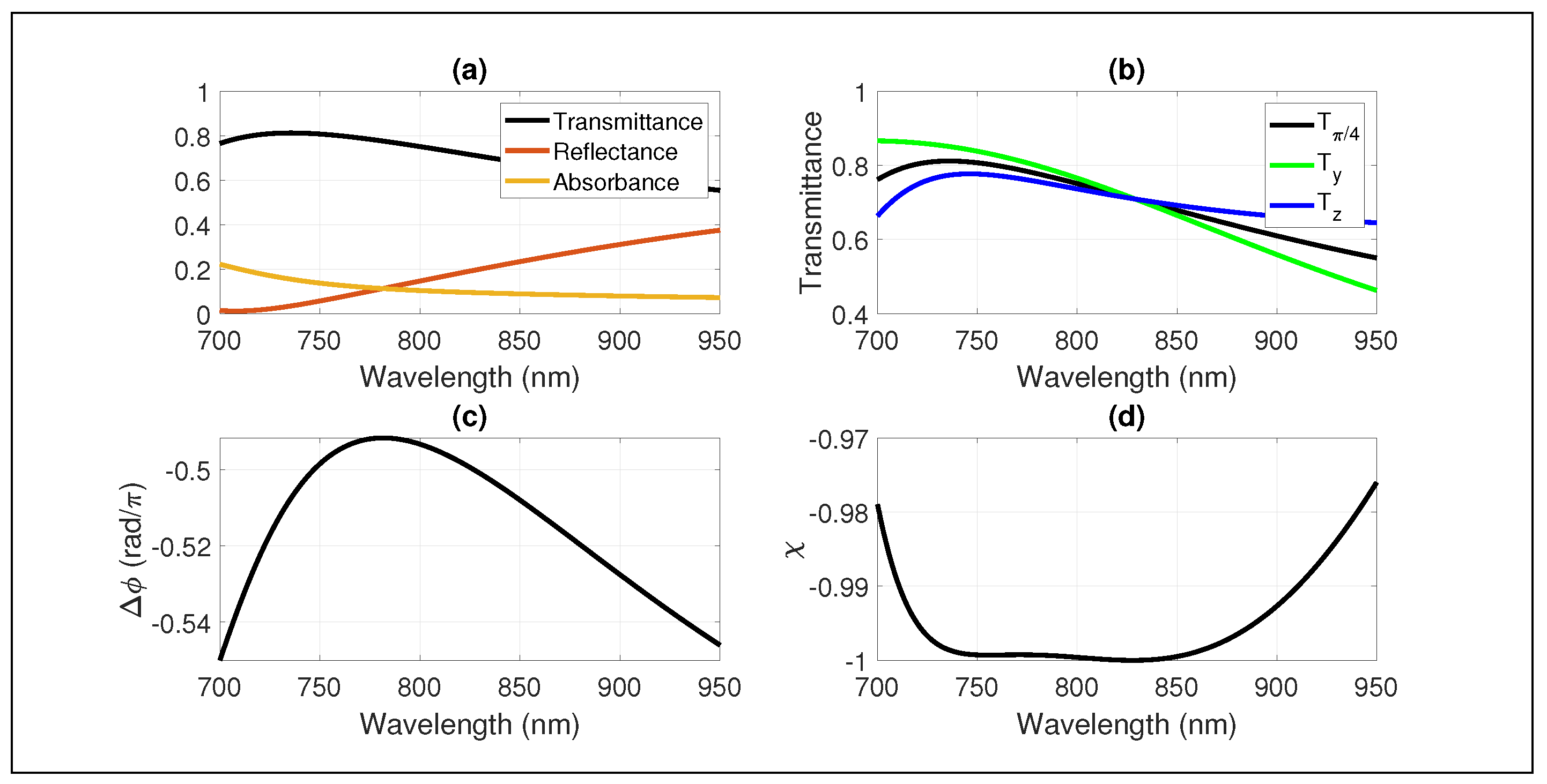
Having established the theoretical framework for evaluating the performance of our quarter-wave plate design, we now turn our attention to its empirical performance metrics. The succeeding Figure 2 presents a comprehensive view of the QWP performance, displaying the transmission, phase shift, and ellipticity from 700 nm to 950 nm. Accompanying this, the complex permittivities of the materials utilized at these wavelength limits are specified in Table 1. These figures are critical, as they provide clear evidence of the ability of QWP to convert linearly polarized light into circularly polarized light, a crucial measure of the device’s utility.
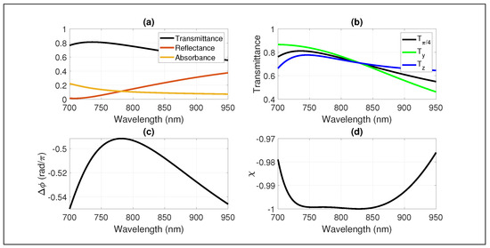
Figure 2.
Performance of the grating structure shown in Figure 1 as a QWP. The input uses a normally incident uniform plane wave with a 45-degree angle of polarization and is simulated over the wavelengths from 700 nm to 950 nm. Presented is the (a) transmittance, reflectance and absorbance of the 45-degree input over the wavelengths. (b) The transmittance split into Y and Z polarizations. (c) The phase difference between the Z and Y polarizations. (d) Ellipticity with respect to wavelength.
This QWP design exceeds the figure of merit (FOM) of 0.99 from 711 nm to 910 nm, having a bandwidth of approximately 200 nm as shown in Figure 2. We described a subwavelength QWP operating on a transmission basis. However, while the individual performance of this QWP is promising, it represents just one component in a more complex system. When we consider these devices as part of an integrated assembly, additional complexities emerge. With metamaterials, especially those that rely on strong resonance, the consideration of near-field effects along with multiple reflections between devices becomes increasingly necessary due to the potential impact on performance of the integrated device.
3. Near-Field Effects and Cascading Behaviors
As optical systems move towards the high-density integration of optical structures with sub-wavelength separations, the interactions of the individual components as well as their interactions within a system need to be known. To design a practical metamaterial for use within a compact optical system, we present an analysis process that showcases why this thorough analysis should be performed for all metamaterial designs. To illustrate our point, we use the grating structure depicted in Figure 1, shown to perform well as a QWP. We perform a near-field analysis, finding the effective length that the QWP operation takes. We also cascade the grating structure, using the effective length as a guide and observe any unique interactions in the system. We should note that the cascaded analysis of two QWPs is to understand the characteristics of the QWP designed and not to design a half-wave plate (HWP). A single device as a HWP would need redesigning, adhering to the current manufacturing standards.
To validate the grating structure’s efficacy as a QWP under a normally incident uniform plane wave, we examined its output to ensure it produces a uniform plane wave to minimize coupling and maintains a phase difference. For the output of the grating structure to be defined as a uniform plane wave, the variances of its field magnitude and phase must approach zero. Deviations in field magnitude or phase can potentially impact device effectiveness when considering an integrated system. Similar analyses may be devised for structured light, oblique incidence, waveguide modes, etc.
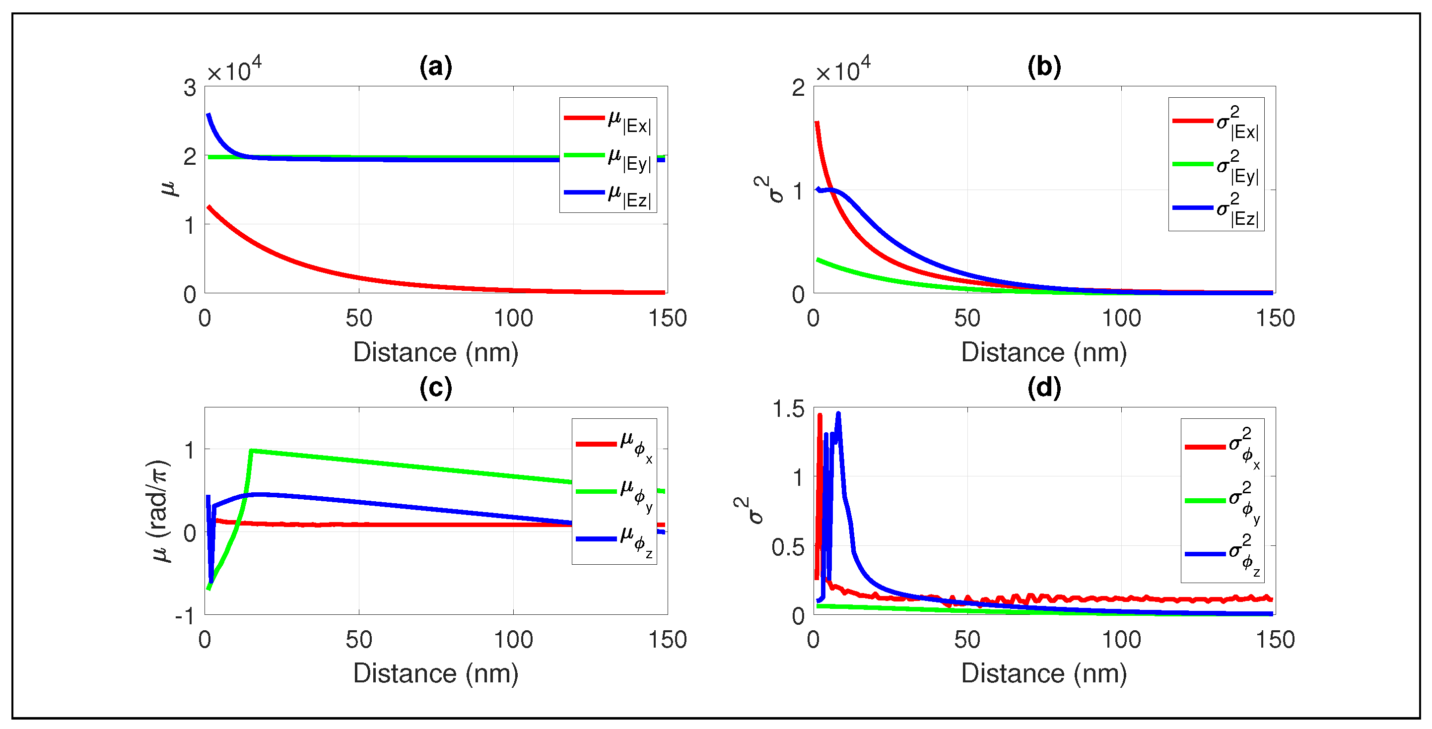
To appropriately simulate and analyze the output characteristics of the designed grating structure shown in Figure 1, modifications were made in which data lines with appropriate meshing were placed every nanometer after the back side of the grating. Using an 800 nm normally incident uniform plane wave with a 45-degree polarization angle, the output results shown in Figure 3 were collected. Figure 3 shows the mean and variance of the field magnitude and phase as a function of distance from the output of the grating structure. From the average field magnitudes, it can be seen that the grating structure has near-field effects, such as producing an X component (i.e., longitudinal cross-polarization) and a spike in the Z component. The field enhancement seen in the Z and X components of the output field magnitude can be mainly attributed to the sharp corners of the metallic portion of the grating [72,73], which can be reduced by increasing the radius of curvature at the corners [72]. This may decrease both the effective length of the QWP and Ohmic losses.
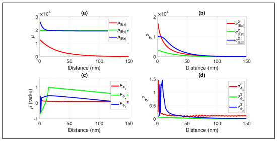
Figure 3.
Near- field analysis of the output of the grating structure using the same physical design as shown in Figure 1. The input is an 800 nm normally incident uniform plane wave with a 45-degree angle of polarization where the input is 150 nm before the grating. The output is sampled every nanometer until 150 nm of travel from the back side of the grating. This diagram displays the (a) mean and (b) variance of the electric field magnitude with respect to the distance from the output of the grating structure, showing that the X component dissipates within 100 nm and the variance of each of the components approaches zero. The (c) mean and the (d) variance of the radian phase components of the electric field polarizations indicate that the Y and Z polarizations have a variance that approaches zero, while the X polarization’s phase contains some variance throughout the measured distance.
While the grating structure is shown to convert some of the input into the X-polarization at the output of the grating structure, the field’s mean magnitude of the X component approaches zero within 100 nm, becoming two orders of magnitude less than either of the other polarizations. The variance of the X-polarization’s phase persists throughout the measured distance. As the X component approaches zero, the non-uniformity it contributes can be considered negligible at the 100 nm distance from the output of the grating structure. With the X component of the field magnitude approaching zero and the variance of the Y and Z polarizations field magnitudes and phase also approaching zero, the output of the grating structure can be considered a uniform plane wave after 100 nm at the 800 nm wavelength. Since there are no resonant spikes within the bandwidth (Figure 2a), the same analysis was performed at the edge cases of the bandwidth (i.e., 711 nm and 910 nm wavelengths) to confirm that the grating structure produced a uniform plane wave at 100 nm after the back side of the grating throughout the bandwidth. These results show that the effective length of the QWP in Figure 1 can be determined to be approximately 200 nm. This includes a 100 nm thick grating structure followed by 100 nm thick silicon dioxide layer on the right side of the grating for the field to stabilize. Due to the near-field effects, clearly shown in Figure 3, the QWP operation is not considered complete until after traveling 100 nm past the output side of the grating.
While it is well known that metamaterials have near-field effects, the effective length of the device is not considered in most works. However, for the appropriate incorporation of a designed metamaterial into a highly dense optical system with sub-wavelength separations, the near-field effects become important.
To analyze how the QWP performs in a cascaded structure, we use the effective length of the QWP found and put two of them consecutively back to back as shown in Figure 4, which illustrates both the geometry and the resultant distributions of the field magnitudes at the near-field. This cascade will lead to the two gratings having a separation of 100 nm, with the rest of the design parameters the same as in Figure 1. Also, the output port will be at 100 nm from the back side of the second grating, simulating two effective QWPs back to back. For the two consecutive QWPs as shown in Figure 4 to perform an effective HWP operation, the final output should be a uniform plane wave and reproduce linearly polarized light with the correct rotation. To determine the two QWPs’ effectiveness as a HWP, we will use the degree of linear polarization (DoLP) and the polarization conversion ratio (PCR). To determine the linearity of the output polarization, we use the DoLP derived from the Stokes parameters in Equation (2), defined as [74,75,76]
where the DoLP can range from 1, representing a perfect linear polarization, to zero, indicating no linear polarization [76]. DoLP = 0.94 may be considered appropriate for a HWP operation [76]. The PCR is determined by the polarization input and expected polarization output. For our system shown in Figure 4, the input has a 45-degree polarization with respect to the Y and Z axes. For a HWP operation with our setup, this should lead to a 90-degree rotation. For our system, the PCR is defined as follows [77,78,79]:
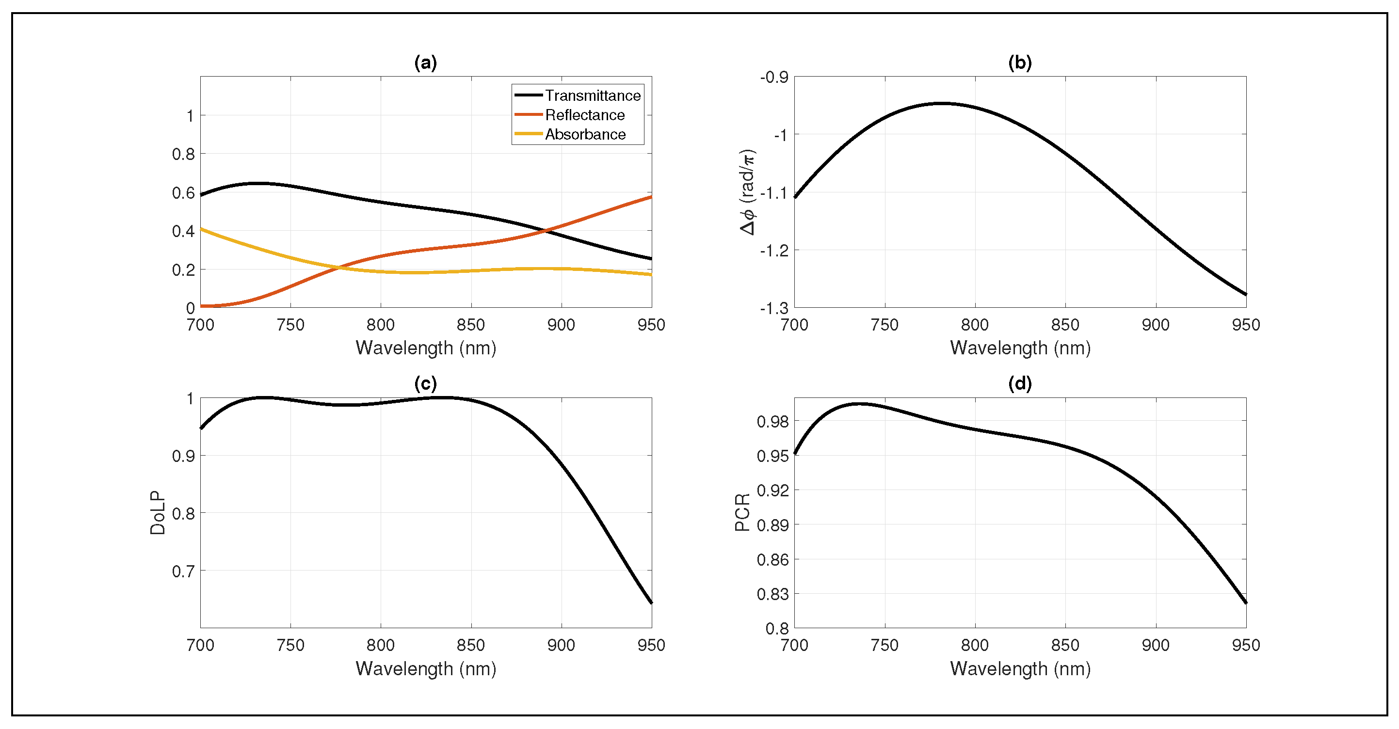
where corresponds to the transmission coefficient magnitude that aligns with the positive polarization angle of the input and corresponds to the expected 90-degree conversion of the output to a negative polarization angle. The PCR FOM that we would like the cascaded system to achieve is 0.98 [71,79]. Using the DoLP and PCR, the effectiveness of the two QWPs cascaded is shown in Figure 5. Analyzing the performance of the cascaded QWP system, it can be seen that the DoLP meets the targeted FOM from 700 nm to 880 nm with a majority of that range achieving >0.98. While the two QWPs provide linearly polarized light over this range, the PCR only achieves a value of >0.94. While the cascaded QWPs do not achieve the desired PCR at 800 nm (i.e., center of the operating bandwidth for the original QWP, see Figure 2d), the desired PCR is achieved from 712 nm to 778 nm.
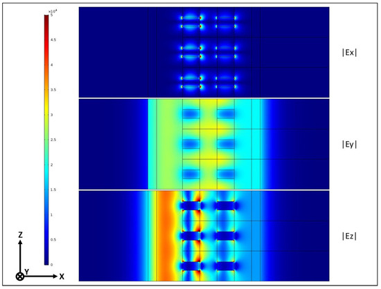
Figure 4.
Two cascaded gratings embedded in silicon dioxide using the the same grating design shown in Figure 1. The gratings are separated by 100 nm due to the effective length found for the grating structure. The magnitudes of the field components are presented at the 800 nm wavelength illustrating the near-field distributions. Vanishing fields on both sides of the geometry are due to the PML and scattering boundary conditions.

Figure 5.
Performance of the 2D cascaded QWP design in Figure 4 from 700 nm to 950 nm wavelength. The output port is placed at 100 nm from the back side of the second grating to simulate two cascaded effective QWPs. (a) Transmittance, reflectance, and absorbance of the 45-degree polarization input over the wavelengths. (b) The phase difference between the Z and Y polarizations. (c) Degree of linear polarization and (d) polarization conversion ratio with respect to wavelength.
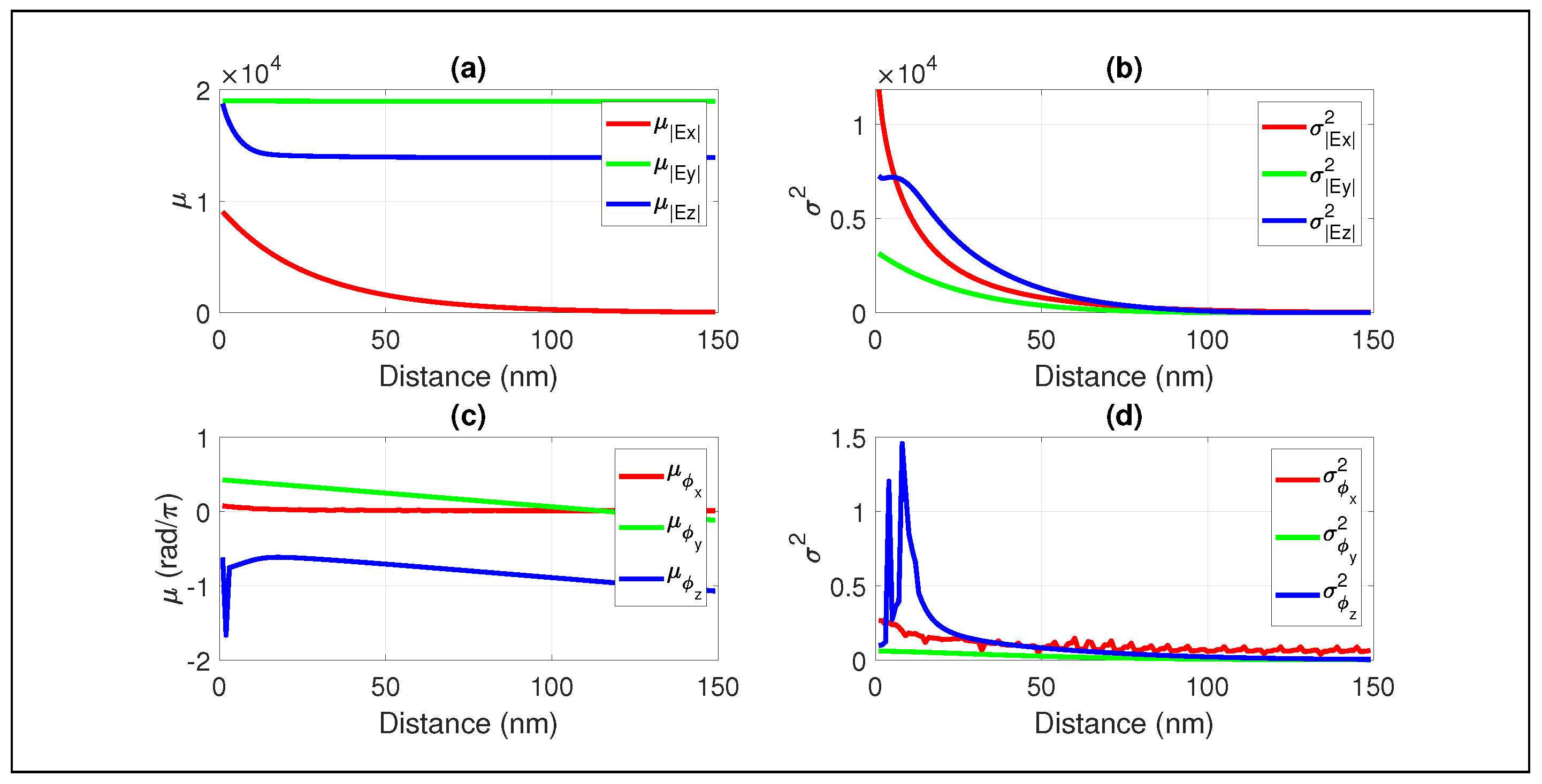
To better understand the impact of the cascaded devices, a near-field analysis was performed, where data were collected every nanometer for 150 nm after the second grating as shown in Figure 6. The near-field results showed that the cascaded QWPs still produced a uniform plane wave at the expected 100 nm after the second grating. From the output characteristics of the individual QWP, the observed magnitude of the Z component of the electric field from the cascaded QWPs deviated notably from expectations. While a slight reduction in the Z component was evident from the analysis presented in Figure 3, multiple reflections appear to have considerably influenced the Z component, resulting in a noticeable deviation from the ideal 90-degree polarization rotation at 800 nm (Figure 5d).
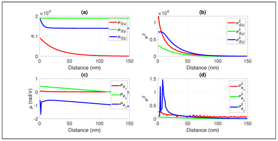
Figure 6.
The near-field output of the cascaded QWPs in Figure 4. The simulation follows the analysis process presented in Figure 3 with an 800 nm normally incident uniform plane wave. This diagram displays the (a) mean and (b) variance of the electric field magnitude with respect to the distance from the output of the second grating structure, showing that the X component dissipates within 100 nm similar to Figure 3, highlighting that the effective length of the QWP remains 100 nm. The (c) mean and the (d) variance of the radian phase components of the electric field polarizations. The output of the cascaded system is shown to be a uniform plane wave, as the Y and Z polarizations have a phase and magnitude variance that approaches zero.
While the observed results for the phase shift and transmittance diverge slightly from what was expected from cascading two QWPs, the deviations can be attributed to near-field effects and multiple reflections between the grating structures. For our designed grating structure, we have the Y and Z polarizations, which have different effective refractive indices, and , respectively, and the refractive index of the surrounding media, which will be written as . In the absence of losses, the transmission coefficient for the Y-polarization can be written as the following [50]:
Similarly, for the Z-polarization
Equations (6) and (7) show that the phase difference between the polarizations is not commensurate with the length due to the refractive index difference of the surrounding medium that results in multiple reflections. Note that when multiple reflections are not present, from Equations (6) and (7), we recover the phase difference , which is linearly proportional to the length. This relationship becomes more complicated when dealing with lossy and inhomogeneous metamaterials and can involve additionally evanescent coupling [26,27,28] and polarization-dependent meta-atom resonances. However, these equations already indicate that putting two of the designed QWPs in series, as shown in Figure 4, will not necessarily produce an ideal phase shift due to the introduction of more interfaces for multiple reflections. Similarly, the dependence of the transmission coefficient magnitudes and on and introduces asymmetry in the transmitted field magnitudes like in Figure 6a.
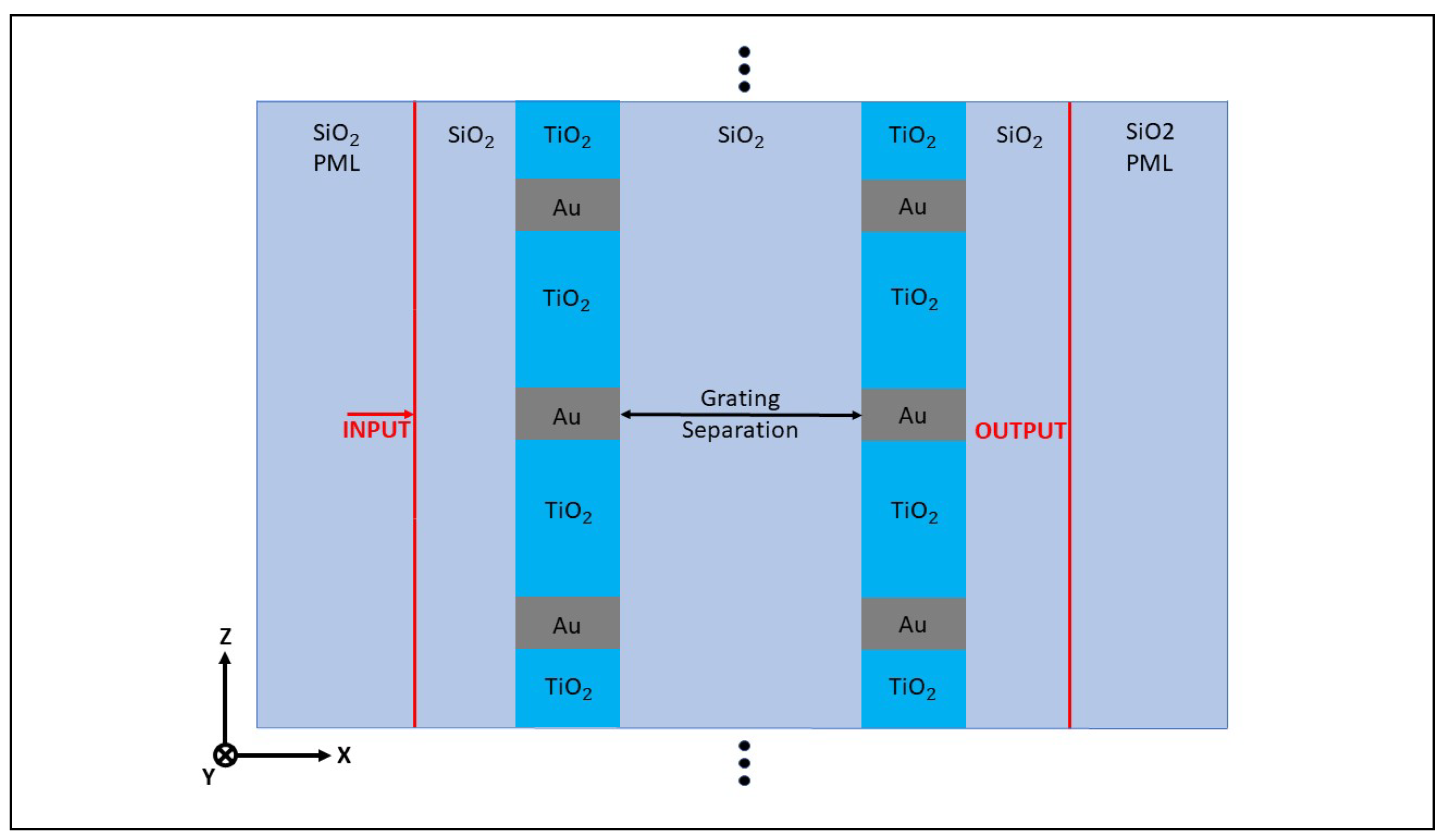
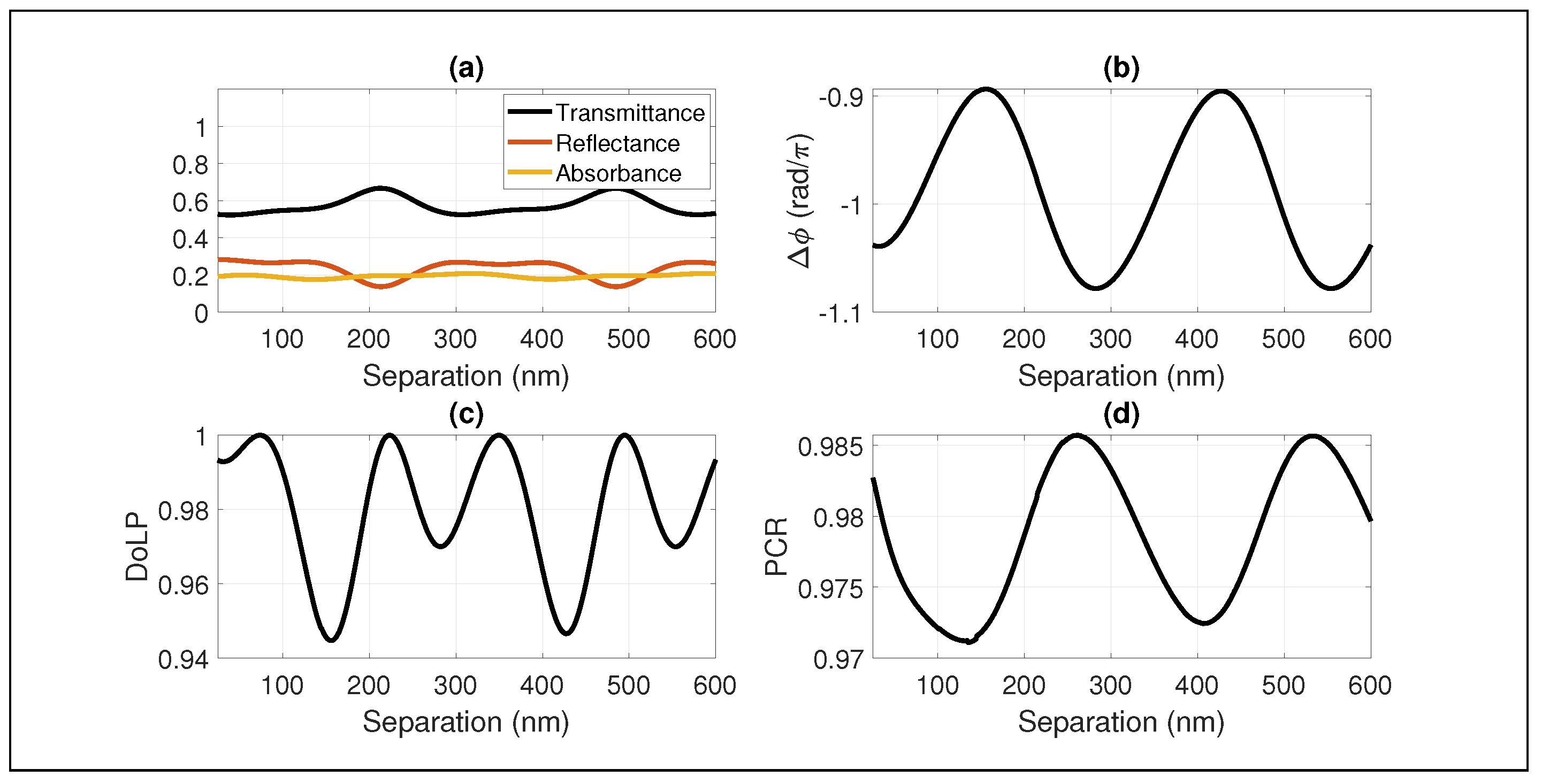
To further show how multiple reflections impact the performance of the cascaded gratings as a HWP, a sweep of separation distances was performed as illustrated in Figure 7. For this simulation, the effective length of the QWP was not adhered to, and the distance between the two gratings was varied from 25 nm to 600 nm. The output of the simulation was measured at 150 nm from the back side of the second grating, ensuring the measured output was a uniform plane wave for each simulation. The input of the simulation was an 800 nm 45-degree polarization angle uniform plane wave for every simulation. Figure 8 shows the performance of the cascaded gratings in Figure 7 with respect to separation distance. A periodic pattern emerged on each of the figures, showing one of the characteristics of multiple reflections between devices. There are two transmittance peaks in Figure 8a, one at the 218 nm separation and one at the 489 nm separation. At these two peaks, the phase shift between the two orthogonal polarizations (i.e., ) is equal to twice the phase shift of a single QWP in Figure 2. This shows that a separation distance between the two gratings can be found, in which the effects of multiple reflections are mitigated and the expected phase shift can be observed. Throughout the sweep of separation distances, the DoLP remained above the desired FOM of 0.94. The output polarization was again unable to achieve the full 90-degree rotation (i.e., PCR = 1), but the desired PCR (i.e., >0.98) was achieved at specific separation distances, highlighting the need for an in-depth analysis of metamaterial structures which presents the performance impact and considerations required for integrating into a larger system.
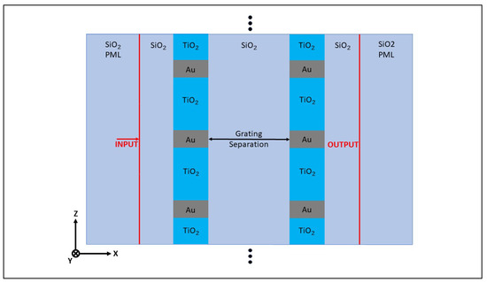
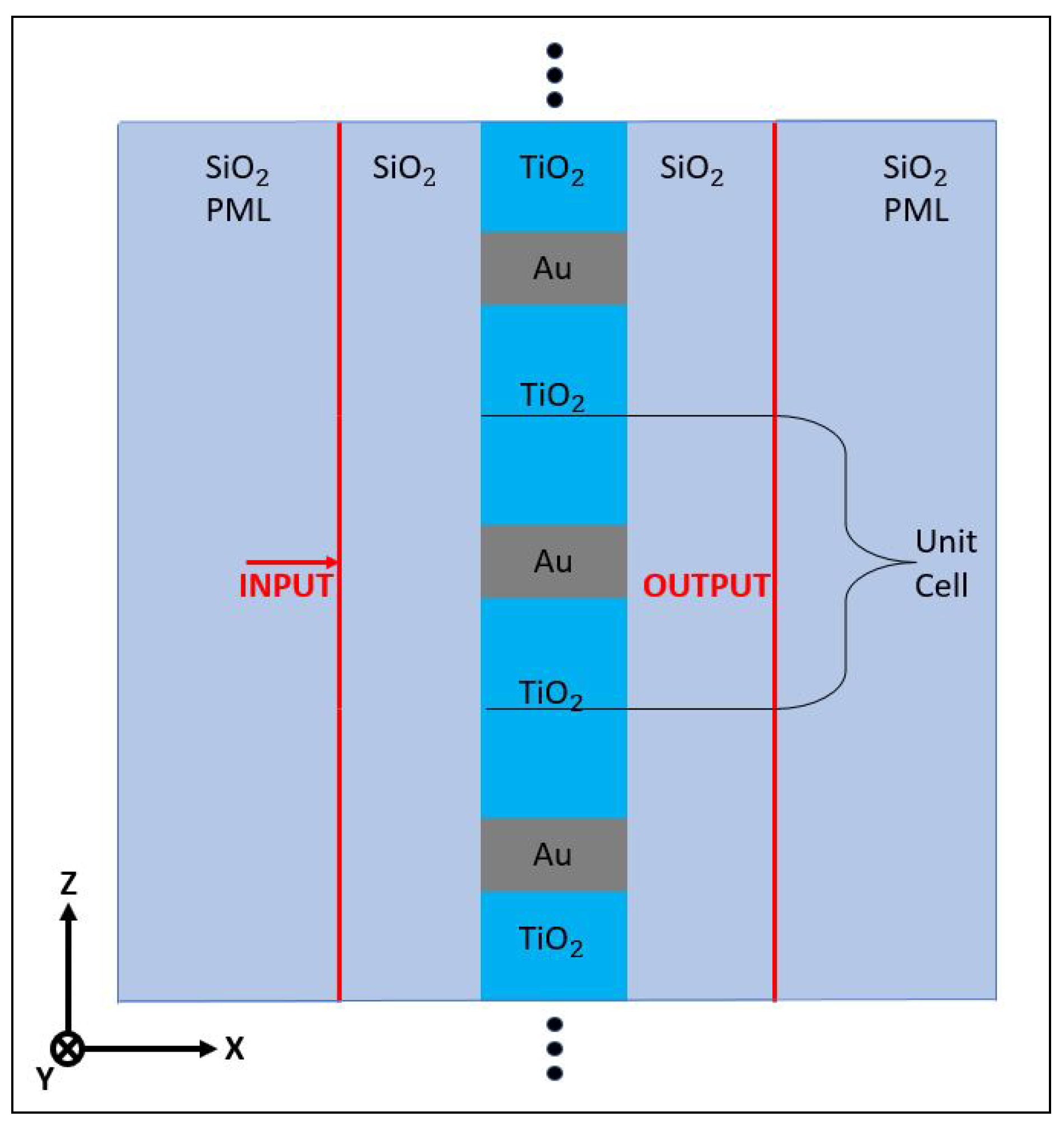
Figure 7.
2D cascaded grating separation simulation schematic following the same design in Figure 4, with varying separation distance between the gratings. Both the input and output ports are 150 nm away from the grating surfaces.
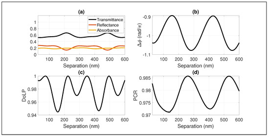
Figure 8.
The simulation results for the physical design in Figure 7 at 800 nm with an input of a normally incident uniform plane wave with a 45-degree polarization angle. Displayed are the (a) transmittance, reflectance, and absorbance of the 45-degree input, (b) the phase difference between the Z and Y polarizations, (c) degree of linear polarization, and (d) polarization conversion ratio with respect to separation distance.
4. Discussion
In this paper, we designed a broadband transmission-based QWP optimized for use around 800 nm. Our QWP stands out for its ultra-thin, broad bandwidth, and transmission-based features, further bolstered by its simple 2D design. A study of its near-field behavior gave rise to an effective length of the device. This notion is significant, as it suggests that a metamaterial’s dimensions should not only be determined by the device’s physical parameters but also by the length required to achieve the desired output. A further analysis was conducted of the designed QWP as part of a cascaded system, highlighting how multiple reflections dramatically increased the loss of the Z component. This had an important effect on the output angle of the cascaded system to never be able to fully achieve the 90-degree rotation expected from cascaded QWPs.
While metamaterials and metadevices have shown to have potential to miniaturize and revolutionize optical systems, the increased complexity of electromagnetic field interactions as these structures approach the near-field region poses a limitation that must be considered. We explored how this can lead to unwanted energy transfer, causing alterations to the transmittance and phase response of the cascaded QWP. Near-field effects are inherent to many metamaterial designs, yet the extent and implications of these effects often go unaddressed in standard design considerations. In the realm of high-density optical assemblies with components separated by sub-wavelength distances, it becomes paramount to grasp the potential interactions between these components. While simulations remain indispensable for every optical system, a prior understanding of device constraints within compact configurations can streamline the design process similar to large scale electronic circuit design. Such comprehension enhances the contributions of individual devices, facilitating the evolution of practical, high-density metamaterial optics. Comprehensive insight into metamaterial properties, inter-device interactions, and near-field dynamics will be pivotal for the advancement of future optical system designs and applications. A promising avenue for future research may involve leveraging auxiliary fields [80,81] to modulate these inter-device interactions and near-field effects, paving the way for dynamic and reconfigurable metadevices.
Author Contributions
Conceptualization, J.D. and D.G.; methodology, J.D. and D.G.; software, J.D.; validation, J.D. and D.G.; formal analysis, J.D.; investigation, J.D.; resources, D.G.; data curation, J.D.; writing—original draft preparation, J.D.; writing—review and editing, J.D. and D.G.; visualization, J.D.; supervision, D.G.; project administration, D.G.; funding acquisition, D.G. All authors have read and agreed to the published version of the manuscript.
Funding
This research received no external funding.
Institutional Review Board Statement
Not applicable.
Informed Consent Statement
Not applicable.
Data Availability Statement
All data are presented in this paper.
Conflicts of Interest
The authors declare no conflict of interest.
References
- Zaidi, A.; Rubin, N.A.; Dorrah, A.H.; Park, J.S.; Capasso, F. Generalized polarization transformations with metasurfaces. Opt. Express 2021, 29, 39065–39078. [Google Scholar] [CrossRef] [PubMed]
- Li, A.; Chen, W.; Wei, H.; Lu, G.; Alù, A.; Qiu, C.W.; Chen, L. Riemann-encircling exceptional points for efficient asymmetric polarization-locked devices. Phys. Rev. Lett. 2022, 129, 127401. [Google Scholar] [CrossRef] [PubMed]
- Liang, Y.; Lin, H.; Koshelev, K.; Zhang, F.; Yang, Y.; Wu, J.; Kivshar, Y.; Jia, B. Full-stokes polarization perfect absorption with diatomic metasurfaces. Nano Lett. 2021, 21, 1090–1095. [Google Scholar] [CrossRef] [PubMed]
- Zhao, J.; Li, N.; Cheng, Y. All-dielectric InSb metasurface for broadband and high-efficient thermal tunable terahertz reflective linear-polarization conversion. Opt. Commun. 2023, 536, 129372. [Google Scholar] [CrossRef]
- Li, J.; Hu, G.; Shi, L.; He, N.; Li, D.; Shang, Q.; Zhang, Q.; Fu, H.; Zhou, L.; Xiong, W.; et al. Full-color enhanced second harmonic generation using rainbow trapping in ultrathin hyperbolic metamaterials. Nat. Commun. 2021, 12, 6425. [Google Scholar] [CrossRef] [PubMed]
- Smith, D.R.; Pendry, J.B.; Wiltshire, M.C.K. Metamaterials and Negative Refractive Index. Science 2004, 305, 788–792. [Google Scholar] [CrossRef]
- Pendry, J.B.; Schurig, D.; Smith, D.R. Controlling electromagnetic fields. Science 2006, 312, 1780–1782. [Google Scholar] [CrossRef]
- Pors, A.; Bozhevolnyi, S.I. Efficient and broadband quarter-wave plates by gap-plasmon resonators. Opt. Express 2018, 26, 7287–7296. [Google Scholar] [CrossRef]
- Cheng, B.; Wang, L.; Zou, Y.; Lv, L.; Li, C.; Xu, Y.; Song, G. Large bandwidth and high-efficiency plasmonic quarter-wave plate. Opt. Express 2021, 29, 16939–16949. [Google Scholar] [CrossRef]
- Zhao, Y.; Alù, A. Manipulating light polarization with ultrathin plasmonic metasurfaces. Phys. Rev. B 2011, 84, 205428. [Google Scholar] [CrossRef]
- Chen, H.T.; Taylor, A.J.; Yu, N. A review of metasurfaces: Physics and applications. Rep. Prog. Phys. 2016, 79, 076401. [Google Scholar] [CrossRef] [PubMed]
- Thangarasu, S.; Siva, V.; Kannan, S.; Murugan, A. Highly Efficient Materials for Photonic Crystal-Based Optical Components. In Photonic Crystal and Its Applications for Next Generation Systems; Springer: Berlin/Heidelberg, Germany, 2023; pp. 53–69. [Google Scholar]
- Liu, D.; Lv, T.; Dong, G.; Liu, C.; Liu, Q.; Zhu, Z.; Li, Y.; Guan, C.; Shi, J. Broadband and wide angle quarter-wave plate based on single-layered anisotropic terahertz metasurface. Opt. Commun. 2021, 483, 126629. [Google Scholar] [CrossRef]
- Wang, D.; Gu, Y.; Gong, Y.; Qiu, C.W.; Hong, M. An ultrathin terahertz quarter-wave plate using planar babinet-inverted metasurface. Opt. Express 2015, 23, 11114–11122. [Google Scholar] [CrossRef]
- Weis, P.; Paul, O.; Imhof, C.; Beigang, R.; Rahm, M. Strongly birefringent metamaterials as negative index terahertz wave plates. Appl. Phys. Lett. 2009, 95, 171104. [Google Scholar] [CrossRef]
- Zhang, Z.; Gong, Y.; Pang, K. Optimization and design on multi-layers of dielectric metasurface as broadband terahertz quarter wave plate. J. Opt. 2022, 24, 105101. [Google Scholar] [CrossRef]
- Nouman, M.T.; Hwang, J.H.; Jang, J.H. Ultrathin terahertz quarter-wave plate based on split ring resonator and wire grating hybrid metasurface. Sci. Rep. 2016, 6, 39062. [Google Scholar] [CrossRef] [PubMed]
- Pors, A.; Nielsen, M.G.; Della Valle, G.; Willatzen, M.; Albrektsen, O.; Bozhevolnyi, S.I. Plasmonic metamaterial wave retarders in reflection by orthogonally oriented detuned electrical dipoles. Opt. Lett. 2011, 36, 1626–1628. [Google Scholar] [CrossRef]
- Takeda, S.; Mizuta, T.; Fuwa, M.; Van Loock, P.; Furusawa, A. Deterministic quantum teleportation of photonic quantum bits by a hybrid technique. Nature 2013, 500, 315–318. [Google Scholar] [CrossRef]
- Masada, G.; Miyata, K.; Politi, A.; Hashimoto, T.; O’brien, J.L.; Furusawa, A. Continuous-variable entanglement on a chip. Nat. Photonics 2015, 9, 316–319. [Google Scholar] [CrossRef]
- Qiang, X.; Zhou, X.; Wang, J.; Wilkes, C.M.; Loke, T.; O’Gara, S.; Kling, L.; Marshall, G.D.; Santagati, R.; Ralph, T.C.; et al. Large-scale silicon quantum photonics implementing arbitrary two-qubit processing. Nat. Photonics 2018, 12, 534–539. [Google Scholar] [CrossRef]
- Arrazola, J.M.; Bergholm, V.; Brádler, K.; Bromley, T.R.; Collins, M.J.; Dhand, I.; Fumagalli, A.; Gerrits, T.; Goussev, A.; Helt, L.G.; et al. Quantum circuits with many photons on a programmable nanophotonic chip. Nature 2021, 591, 54–60. [Google Scholar] [CrossRef]
- Cheng, X.; Chang, K.C.; Xie, Z.; Sarihan, M.C.; Lee, Y.S.; Li, Y.; Xu, X.; Vinod, A.K.; Kocaman, S.; Yu, M.; et al. A chip-scale polarization-spatial-momentum quantum SWAP gate in silicon nanophotonics. Nat. Photonics 2023, 17, 656–665. [Google Scholar] [CrossRef]
- Zhang, W.; Cheng, K.; Wu, C.; Wang, Y.; Li, H.; Zhang, X. Implementing quantum search algorithm with metamaterials. Adv. Mater. 2018, 30, 1703986. [Google Scholar] [CrossRef]
- Cheng, K.; Zhang, W.; Wei, Z.; Fan, Y.; Xu, C.; Wu, C.; Zhang, X.; Li, H. Simulate Deutsch-Jozsa algorithm with metamaterials. Opt. Express 2020, 28, 16230–16243. [Google Scholar] [CrossRef]
- Ranjbar, A.; Grbic, A. Broadband, multiband, and multifunctional all-dielectric metasurfaces. Phys. Rev. Appl. 2019, 11, 054066. [Google Scholar] [CrossRef]
- Raeker, B.O.; Grbic, A. Compound metaoptics for amplitude and phase control of wave fronts. Phys. Rev. Lett. 2019, 122, 113901. [Google Scholar] [CrossRef]
- Wu, Z.; Ra’di, Y.; Grbic, A. Tunable metasurfaces: A polarization rotator design. Phys. Rev. X 2019, 9, 011036. [Google Scholar] [CrossRef]
- Raeker, B.O.; Grbic, A. Lossless complex-valued optical-field control with compound metaoptics. Phys. Rev. Appl. 2021, 15, 054039. [Google Scholar] [CrossRef]
- Zhou, Y.; Kravchenko, I.I.; Wang, H.; Nolen, J.R.; Gu, G.; Valentine, J. Multilayer noninteracting dielectric metasurfaces for multiwavelength metaoptics. Nano Lett. 2018, 18, 7529–7537. [Google Scholar] [CrossRef]
- Zhou, Y.; Kravchenko, I.I.; Wang, H.; Zheng, H.; Gu, G.; Valentine, J. Multifunctional metaoptics based on bilayer metasurfaces. Light. Sci. Appl. 2019, 8, 80. [Google Scholar] [CrossRef] [PubMed]
- Zhou, Y.; Zheng, H.; Kravchenko, I.I.; Valentine, J. Flat optics for image differentiation. Nat. Photonics 2020, 14, 316–323. [Google Scholar] [CrossRef]
- Davis, J.E.; Güney, D.O. Effect of loss on linear optical quantum logic gates. J. Opt. Soc. Am. B 2021, 38, C153–C159. [Google Scholar] [CrossRef]
- Zhang, X.; Davis, J.E.; Güney, D.Ö. Ultra-thin metamaterial beam splitters. Appl. Sci. 2019, 10, 53. [Google Scholar] [CrossRef]
- Genevet, P.; Capasso, F.; Aieta, F.; Khorasaninejad, M.; Devlin, R. Recent advances in planar optics: From plasmonic to dielectric metasurfaces. Optica 2017, 4, 139–152. [Google Scholar] [CrossRef]
- Bin-Alam, M.S.; Reshef, O.; Mamchur, Y.; Alam, M.Z.; Carlow, G.; Upham, J.; Sullivan, B.T.; Ménard, J.M.; Huttunen, M.J.; Boyd, R.W.; et al. Ultra-high-Q resonances in plasmonic metasurfaces. Nat. Commun. 2021, 12, 974. [Google Scholar] [CrossRef]
- Zhang, S.; Genov, D.A.; Wang, Y.; Liu, M.; Zhang, X. Plasmon-induced transparency in metamaterials. Phys. Rev. Lett. 2008, 101, 047401. [Google Scholar] [CrossRef]
- Güney, D.Ö.; Koschny, T.; Soukoulis, C.M. Surface plasmon driven electric and magnetic resonators for metamaterials. Phys. Rev. B 2011, 83, 045107. [Google Scholar] [CrossRef]
- Tian, Y.; Ghanekar, A.; Ricci, M.; Hyde, M.; Gregory, O.; Zheng, Y. A review of tunable wavelength selectivity of metamaterials in near-field and far-field radiative thermal transport. Materials 2018, 11, 862. [Google Scholar] [CrossRef]
- Pendry, J. Manipulating the near field with metamaterials. Opt. Photonics News 2004, 15, 32–37. [Google Scholar] [CrossRef]
- Von Cube, F.; Irsen, S.; Diehl, R.; Niegemann, J.; Busch, K.; Linden, S. From isolated metaatoms to photonic metamaterials: Evolution of the plasmonic near-field. Nano Lett. 2013, 13, 703–708. [Google Scholar] [CrossRef]
- Sadatgol, M.; Bihari, N.; Pearce, J.M.; Guney, D.O. Scalable honeycomb top contact to increase the light absorption and reduce the series resistance of thin film solar cells. Opt. Mater. Express 2019, 9, 256–268. [Google Scholar] [CrossRef]
- Adams, W.; Ghoshroy, A.; Guney, D.O. Plasmonic superlens imaging enhanced by incoherent active convolved illumination. ACS Photonics 2018, 5, 1294–1302. [Google Scholar] [CrossRef]
- Ou, K.; Yu, F.; Li, G.; Wang, W.; Miroshnichenko, A.E.; Huang, L.; Wang, P.; Li, T.; Li, Z.; Chen, X.; et al. Mid-infrared polarization-controlled broadband achromatic metadevice. Sci. Adv. 2020, 6, eabc0711. [Google Scholar] [CrossRef] [PubMed]
- Chen, M.K.; Chu, C.H.; Lin, R.J.; Chen, J.W.; Huang, Y.T.; Huang, T.T.; Kuo, H.Y.; Tsai, D.P. Optical meta-devices: Advances and applications. Jpn. J. Appl. Phys. 2019, 58, SK0801. [Google Scholar] [CrossRef]
- Xiao, S.; Wang, T.; Liu, T.; Zhou, C.; Jiang, X.; Zhang, J. Active metamaterials and metadevices: A review. J. Phys. Appl. Phys. 2020, 53, 503002. [Google Scholar] [CrossRef]
- Zheludev, N.I.; Kivshar, Y.S. From metamaterials to metadevices. Nat. Mater. 2012, 11, 917–924. [Google Scholar] [CrossRef]
- Chen, F. Near-Field Coupling and Homogenization in All-Dielectric Metamaterials and Their Effects on Applications; Michigan Technological University: Houghton, MI, USA, 2014. [Google Scholar]
- Palmieri, A.; Dorrah, A.H.; Yang, J.; Oh, J.; Dainese, P.; Capasso, F. Do bilayer metasurfaces behave as a stack of decoupled single-layer metasurfaces? arXiv 2023, arXiv:2309.14960. [Google Scholar]
- Saleh, B.E.; Teich, M.C. Fundamentals of Photonics; John Wiley & Sons: Hoboken, NJ, USA, 2019. [Google Scholar]
- Chen, H.T. Interference theory of metamaterial perfect absorbers. Opt. Express 2012, 20, 7165–7172. [Google Scholar] [CrossRef]
- Aslam, M.I.; Güney, D.Ö. On negative index metamaterial spacers and their unusual optical properties. Prog. Electromagn. Res. B 2013, 47, 203. [Google Scholar] [CrossRef]
- Zhang, X.; Adams, W.; Güney, D.Ö. Analytical description of inverse filter emulating the plasmon injection loss compensation scheme and implementation for ultrahigh-resolution hyperlens. JOSA B 2017, 34, 1310–1318. [Google Scholar] [CrossRef]
- Gehr, R.J.; Boyd, R.W. Optical properties of nanostructured optical materials. Chem. Mater. 1996, 8, 1807–1819. [Google Scholar] [CrossRef]
- Siefke, T.; Kroker, S.; Pfeiffer, K.; Puffky, O.; Dietrich, K.; Franta, D.; Ohlídal, I.; Szeghalmi, A.; Kley, E.B.; Tünnermann, A. Materials pushing the application limits of wire grid polarizers further into the deep ultraviolet spectral range. Adv. Opt. Mater. 2016, 4, 1780–1786. [Google Scholar] [CrossRef]
- Siefke, T.; Kley, E.B.; Tünnermann, A.; Kroker, S. Design and fabrication of titanium dioxide wire grid polarizer for the far ultraviolet spectral range. In Proceedings of the Nanoengineering: Fabrication, Properties, Optics, and Devices XIII; SPIE: Bellingham, WA, USA, 2016; Volume 9927, pp. 22–27. [Google Scholar]
- Pang, Y.; Gordon, R. Metal nano-grid reflective wave plate. Opt. Express 2009, 17, 2871–2879. [Google Scholar] [CrossRef] [PubMed]
- Lalanne, P.; Lemercier-Lalanne, D. On the effective medium theory of subwavelength periodic structures. J. Mod. Opt. 1996, 43, 2063–2085. [Google Scholar] [CrossRef]
- Uriri, S.A.; Tashima, T.; Zhang, X.; Asano, M.; Bechu, M.; Güney, D.O.; Yamamoto, T.; Özdemir, S.K.; Wegener, M.; Tame, M.S. Active control of a plasmonic metamaterial for quantum state engineering. Phys. Rev. A 2018, 97, 053810. [Google Scholar] [CrossRef]
- Wang, D.; Liu, W.; Xiao, Q.; Shi, J. Embedded metal-wire nanograting and its application in an optical polarization beam splitter/combiner. Appl. Opt. 2008, 47, 312–316. [Google Scholar] [CrossRef]
- Alasaarela, T. Atomic Layer Deposited Titanium Dioxide in Optical Waveguiding Applications; Aalto University: Espoo, Finland, 2011. [Google Scholar]
- Sarkar, S.; Gupta, V.; Tsuda, T.; Gour, J.; Singh, A.; Aftenieva, O.; Steiner, A.M.; Hoffmann, M.; Kumar, S.; Fery, A.; et al. Plasmonic charge transfers in large-scale metallic and colloidal photonic crystal slabs. Adv. Funct. Mater. 2021, 31, 2011099. [Google Scholar] [CrossRef]
- Zabelin, D.; Zabelina, A.; Miliutina, E.; Trelin, A.; Elashnikov, R.; Nazarov, D.; Maximov, M.; Kalachyova, Y.; Sajdl, P.; Lancok, J.; et al. Design of hybrid Au grating/TiO2 structure for NIR enhanced photo-electrochemical water splitting. Chem. Eng. J. 2022, 443, 136440. [Google Scholar] [CrossRef]
- Grandi, S.; Nielsen, M.P.; Cambiasso, J.; Boissier, S.; Major, K.D.; Reardon, C.; Krauss, T.F.; Oulton, R.F.; Hinds, E.; Clark, A.S. Hybrid plasmonic waveguide coupling of photons from a single molecule. APL Photonics 2019, 4, 086101. [Google Scholar] [CrossRef]
- Rakić, A.D.; Djurišić, A.B.; Elazar, J.M.; Majewski, M.L. Optical properties of metallic films for vertical-cavity optoelectronic devices. Appl. Opt. 1998, 37, 5271–5283. [Google Scholar] [CrossRef]
- Rodríguez-de Marcos, L.V.; Larruquert, J.I.; Méndez, J.A.; Aznárez, J.A. Self-consistent optical constants of SiO2 and Ta2O5 films. Opt. Mater. Express 2016, 6, 3622–3637. [Google Scholar] [CrossRef]
- Ma, X.; Zhao, H.; Zeng, Y.; Gao, S.; Cheng, J.; He, Q.; Mao, J.; Zhou, C.; Xin, G.; Rao, Z. Stokes parameters measurement system designed by symmetric division of amplitude with double quarter-wave plate. Opt. Commun. 2023, 549, 129888. [Google Scholar] [CrossRef]
- Collett, E. Field Guide to Polarization; SPIE: Bellingham, WA, USA, 2005. [Google Scholar]
- Cong, L.; Xu, N.; Gu, J.; Singh, R.; Han, J.; Zhang, W. Highly flexible broadband terahertz metamaterial quarter-wave plate. Laser Photonics Rev. 2014, 8, 626–632. [Google Scholar] [CrossRef]
- Zhao, J.X.; Song, J.L.; Zhou, Y.; Liu, Y.C.; Zhou, J.H. Switching between the functions of half-wave plate and quarter-wave plate simply by using a vanadium dioxide film in a terahertz metamaterial. Chin. Phys. Lett. 2020, 37, 064204. [Google Scholar] [CrossRef]
- Luo, J.; Shi, X.; Luo, X.; Hu, F.; Li, G. Broadband switchable terahertz half-/quarter-wave plate based on metal-VO2 metamaterials. Opt. Express 2020, 28, 30861–30870. [Google Scholar] [CrossRef]
- Güney, D.Ö.; Koschny, T.; Soukoulis, C.M. Reducing ohmic losses in metamaterials by geometric tailoring. Phys. Rev. B 2009, 80, 125129. [Google Scholar] [CrossRef]
- Adams, W.; Sadatgol, M.; Güney, D.Ö. Review of near-field optics and superlenses for sub-diffraction-limited nano-imaging. AIP Adv. 2016, 6, 100701. [Google Scholar] [CrossRef]
- Goudail, F.; Bénière, A. Estimation precision of the degree of linear polarization and of the angle of polarization in the presence of different sources of noise. Appl. Opt. 2010, 49, 683–693. [Google Scholar] [CrossRef]
- Chen, D.; Zeng, H.; Qi, Y.; Liu, H.; Xue, Q.; Sun, X. Single-layer all-dielectric quarter-wave plate and half-wave plate metasurfaces for polarization conversion in the visible light region. Opt. Eng. 2022, 61, 025104. [Google Scholar] [CrossRef]
- Luo, X.; Hu, F.; Li, G. Broadband switchable terahertz half-/quarter-wave plate based on VO2-metal hybrid metasurface with over/underdamped transition. J. Phys. Appl. Phys. 2021, 54, 505111. [Google Scholar] [CrossRef]
- Wang, D.C.; Sun, S.; Feng, Z.; Tan, W.; Qiu, C.W. Multipolar-interference-assisted terahertz waveplates via all-dielectric metamaterials. Appl. Phys. Lett. 2018, 113, 201103. [Google Scholar] [CrossRef]
- Zi, J.; Xu, Q.; Wang, Q.; Tian, C.; Li, Y.; Zhang, X.; Han, J.; Zhang, W. Antireflection-assisted all-dielectric terahertz metamaterial polarization converter. Appl. Phys. Lett. 2018, 113, 101104. [Google Scholar] [CrossRef]
- Ding, F.; Wang, Z.; He, S.; Shalaev, V.M.; Kildishev, A.V. Broadband high-efficiency half-wave plate: A supercell-based plasmonic metasurface approach. ACS Nano 2015, 9, 4111–4119. [Google Scholar] [CrossRef]
- Sadatgol, M.; Özdemir, Ş.K.; Yang, L.; Güney, D.Ö. Plasmon injection to compensate and control losses in negative index metamaterials. Phys. Rev. Lett. 2015, 115, 035502. [Google Scholar] [CrossRef] [PubMed]
- Ghoshroy, A.; Özdemir, Ş.K.; Güney, D.Ö. Loss compensation in metamaterials and plasmonics with virtual gain. Opt. Mater. Express 2020, 10, 1862–1880. [Google Scholar] [CrossRef]

Disclaimer/Publisher’s Note: The statements, opinions and data contained in all publications are solely those of the individual author(s) and contributor(s) and not of MDPI and/or the editor(s). MDPI and/or the editor(s) disclaim responsibility for any injury to people or property resulting from any ideas, methods, instructions or products referred to in the content. |
© 2023 by the authors. Licensee MDPI, Basel, Switzerland. This article is an open access article distributed under the terms and conditions of the Creative Commons Attribution (CC BY) license (https://creativecommons.org/licenses/by/4.0/).