Article

The Mechanical Properties of Functionally Graded Lattice Structures Derived Using Computer-Aided Design for Additive Manufacturing

1
Graduate School of Natural and Applied Sciences, Gazi University, Ankara 06560, Turkey
2
Department of Industrial Design Engineering, Gazi University, Ankara 06560, Turkey
*
Author to whom correspondence should be addressed.
Appl. Sci. 2023, 13(21), 11667; https://doi.org/10.3390/app132111667
Submission received: 29 September 2023 / Revised: 14 October 2023 / Accepted: 18 October 2023 / Published: 25 October 2023
(This article belongs to the Special Issue Advanced Manufacturing Technologies and Their Applications, Volume II)

Abstract

:
This study aims to investigate the mechanical properties of Functionally Graded Lattice Structures (FGLSs) and to determine their industrial application possibilities through additive manufacturing. For this purpose, lattice structures with uniform and horizontal, vertical and radially graded configurations are designed using auxetic unit cells were fabricated with RGD720 photopolymer resin using Material Jetting. FGLSs are compared with uniform structures in regards with deformation behavior, structural strength and energy absorption. The results showed that the most significant deviation in the strut diameters of the uniform lattice structures was seen in the rotation lattice structure at 8.2%. The lowest deviation was seen in the chiral structure, which deviated by 5.4%. The lowest deviations (between 3.4% and 9%) in FGLSs were obtained in chiral structures. The highest relative density value (0.3049 g/cm3) among all configurations was observed in the vertically graded chiral structure. The lowest relative density value (0.1865 g/cm3) was obtained in uniform re-entrant structures. According to the compression test results, the highest compressive stress (2.61513 MPa) and elastic modulus (84.63192 MPa) were formed in the rotation structure. The maximum energy absorption capacity value (19.381 KJ) and the maximum specific energy absorption value (3649.905 KJ/kg) were obtained in the uniform chiral structure.

1. Introduction

Lattice structures have become an innovative three-dimensional (3D) design approach for weight reduction and energy absorption. These structures have greater crush strength against crushing loads due to the complex geometry of the struts, resulting in increased energy absorption efficiency [1]. Lattice structures, which have a lower density than solid structures, affect mechanical properties such as energy absorption [2], heat dissipation [3], stress–strain properties [4], deformation behavior [5] and compressive strength [6]. Lattice structures have been used in many industries, such as biomedical, aerospace and automotive, because they offer high-strength and lightweight structures [7]. Uniform lattice structures, frequently used in these industries, consist of nodes positioned in a certain order and at equal intervals, with struts connecting these nodes. On the other hand, the need for structures with mechanical properties that vary spatially along the structure has brought the use of functionally graded structures to prominence, as well as uniform lattice structures. Functionally graded materials (FGMs) are used to produce components with variable mechanical properties, depending on the product’s function [8]. Grading in FGMs is usually achieved by a gradient transition in material or design [9]. This gradient transition can be achieved via a dispersed to interconnected second phase structure [10] or by the arrangement of unit cells of varying sizes, shapes and orientations [11]. Additive Manufacturing (AM) technologies, which are at the forefront with the production of customized components, aim to gradually change the material organization in components by enabling the production of FGMs with controlled porosity [8]. The additive manufacturing of functionally graded materials gave rise to the term Functionally Graded Additive Manufacturing (FGAM). There are two different approaches for FGAM. In the first approach, gradient lattice structures are created by varying the printing parameters (laser power, laser speed, scanning range, etc.), but this approach does not provide proper control of the porous structure at the microscale [9,12]. In the second approach, CAD-based design, a series of unit cells are arranged in a specific order by shape, size and orientation to create gradient lattice structures in a controlled manner [9]. In this approach, Functionally Graded Lattice Structures (FGLSs) created with CAD software are structures in which the density of the structure is functionally graded instead of being uniform [13].
In contrast to uniform structures, the use of unit cells of varying sizes in FGLSs allows porous scaffolds to fulfil their function [1,14,15]. Recent studies show that the porosity of lattice structures can be graded by varying the strut thickness and size [16,17,18]. The strut diameters of the cellular units can be changed within the desired relative density range using different software in the FGLSs [13]. The relative density is the ratio of the density of the resulting lattice to the density of the base material [19]. In FGLSs, strut diameters and lengths, as well as unit cell sizes, shapes and orientations, can be varied to achieve a dimensional transition in porosity [13]. This allows gradient structures to be optimized for different applications and provides lower weight than uniform lattice structures with similar mechanical properties. The ability to design FGLSs to seamlessly transition using different unit cells can improve the overall mechanical performance of the structure. Overall, FGLSs offer a higher level of design flexibility and high performance compared to uniform lattice structures. In addition, FGLSs can be designed with progressive energy absorption features to increase their ability to withstand impacts and other high-energy loading conditions.
Previous research on the AM fabrication of FGLSs has mainly focused on the use of CAD software for pore shape, size and density variation. Maskery et al. (2017) investigated the energy absorption, deformation processes and mechanical performance of gradient and uniform lattice structures [16]. According to their results, the energy absorbed by uniform structures increased linearly with compressive strain. Additionally, they reported that FGLSs weaken periodically from low-density upper layers to high-density lower layers. Bai et al. (2020) created structures with different densities and configurations by varying the unidirectional dimension of the unit cell [17]. The specimens fabricated using Selective Laser Sintering (SLS) were tested with a quasi-static compression test. The results showed that the gradient structure has strong strength properties under small amounts of stress, while it has high-performance properties under large amounts of stress. Al-Saedi et al. (2018) performed experimental compression tests and Finite Element Analysis (FEA) to compare the mechanical properties and energy absorption capacity of lattice structures fabricated using Selective Laser Melting (SLM) [20]. The total energy absorption per unit volume of FGLSs was higher than the uniform structure. Although FGLSs entered the onset of densification strain earlier than the uniform structure, they were able to absorb higher amounts of energy than the uniform structure. Takezawa et al. (2019) optimized the gradient lattice density distribution by choosing the strut diameter as the design variable [18]. Although there were observable accuracy errors between the results obtained from the optimization and full-scale models, the optimization performance was reported to be successful.
Many parameters, such as the internal design of unit cells, porosity, mechanical strength, weight, compression time, etc., affect the production of porous parts to be used in industrial applications. On the other hand, the internal structure of cellular structures can also be designed in such a way that deformation results in negative Poisson’s ratio behavior [21]. These structures, defined as auxetic materials, have many engineering advantages such as high energy absorption, impact resistance and high fracture and shear resistance [22]. Therefore, auxetic structures can be used in the production of automotive components such as tires, bumpers and energy absorption devices [1] The main load-carrying properties of eutectic materials are that when a compressive load is applied in the longitudinal direction, the eutectic material contracts rather than expands in the lateral direction. Thus, under compression, the eutectic material moves towards the load and increases the stiffness of the structure around the point where the load is applied. Hou at al. (2018) proposed gradient auxetic cellular structures to design a superior structure in terms of energy efficiency [1]. The results showed that gradient structures have a lower resistance force and a higher energy absorption capacity than uniform structures. Similarly, Qiao and Chen, (2015) created both uniform and functionally graded structures using unit cells with double arrowhead honeycomb geometry [23]. The quasi-static and impact behaviors of these structures were investigated. It was observed that the FGLSs have a higher energy absorption capacity under high-speed impacts. There are also studies in the literature that use different approaches to construct FGLSs [24,25,26,27,28].
There have been several studies on the AM fabrication of FGLSs. Recently, the high-resolution capability, the use of hard and soft resins in a single printing process, inherent morphing capabilities and simplified finishing activities have motivated the use of Material Jetting (MJ) for the fabrication of lattice structures [29]. MJ enables the printing of thinner layers than other polymer printing techniques, resulting in products with high dimensional accuracy and low surface roughness [29,30]. In addition to the photopolymers commonly used as printing materials in MJ, Polylactic Acid (PLA), Acrylonitrile Butadiene Styrene (ABS), Polyamide (PA) and their composites can also be used [31]. The increase in stress and elongation of MJ-printed parts over time leads to the use of this technology for the fabrication of lattice structures [32]. The use of composite materials to improve the mechanical properties of MJ-printed lattice structures is widespread. It was observed that the compressive stress [33], tensile stress [34], impact resistance and energy absorption properties [35,36] of lattice structures fabricated with different composite materials via MJ were significantly strengthened. On the other hand, in addition to the use of composite materials, hybrid designs have also been used in recent years to improve the mechanical properties of these lattice structures [37]. They aimed to strengthen the mechanical properties of the lattice structure by transforming it into a graded form with hybrid designs.
Based on a literature review, it was found that there are few studies on the design, optimization and mechanical properties of MJ-fabricated uniform lattice structures. However, studies focusing on the CAD-based design and MJ fabrication of FGLSs, which are multifunctional due to the customizability of their structural distribution and performance, are quite limited. The aim of this study is to compare FGLSs and uniform structures obtained with three different auxetic unit cells in terms of mechanical properties and energy absorption. The main contribution of this study is the demonstration of the potential for the MJ fabrication of FGLSs designed with a parametric CAD plug-in that allows the use of customized unit cells. The novelty of this study is the presentation of a systematic approach focusing on the design and manufacturing process of FGLSs with different configurations (horizontal, vertical and radial) and varying mechanical properties in line with the target function. Another unique contribution of this study is the fabrication of auxetic FGLSs with RGD720 photopolymer resin using MJ, in contrast to the literature studies that mostly focus on the fabrication of metal-based FGLSs. Additionally, the mechanical test results of this study will serve as a reference for energy absorption and load-bearing applications to be realized in this field and will facilitate the process of conscious lattice structure fabrication.

2. Methodology

The FGLS design phase involves creating the lattice geometry, selecting the lattice topology, determining the unit cell types and setting the lattice parameters to provide the desired boundary conditions [38]. The choice of unit cell geometry is one of the key decisions in the design process of a lattice. Unit cell libraries are available in many CAD software programs and are often used to select lightweight additively manufactured parts. The choice of geometry, material and manufacturing approach is important in order for the parts to be produced with AM and to meet the desired function [39]. In this study, grasshopper software was used for the continuous and regular grading of the strut diameters of different unit cells. The designed gradient and uniform lattice structures were fabricated by means of the MJ technique using polymeric materials. The difficulties encountered in the manufacturing process of lattice structures, such as pore shape and size control, cause these structures to be realized mostly through experiments and simulations [40,41,42]. Therefore, in this study, the mechanical properties of 3D printed horizontal, vertical and radially graded and uniform lattice structures were tested via compression tests.

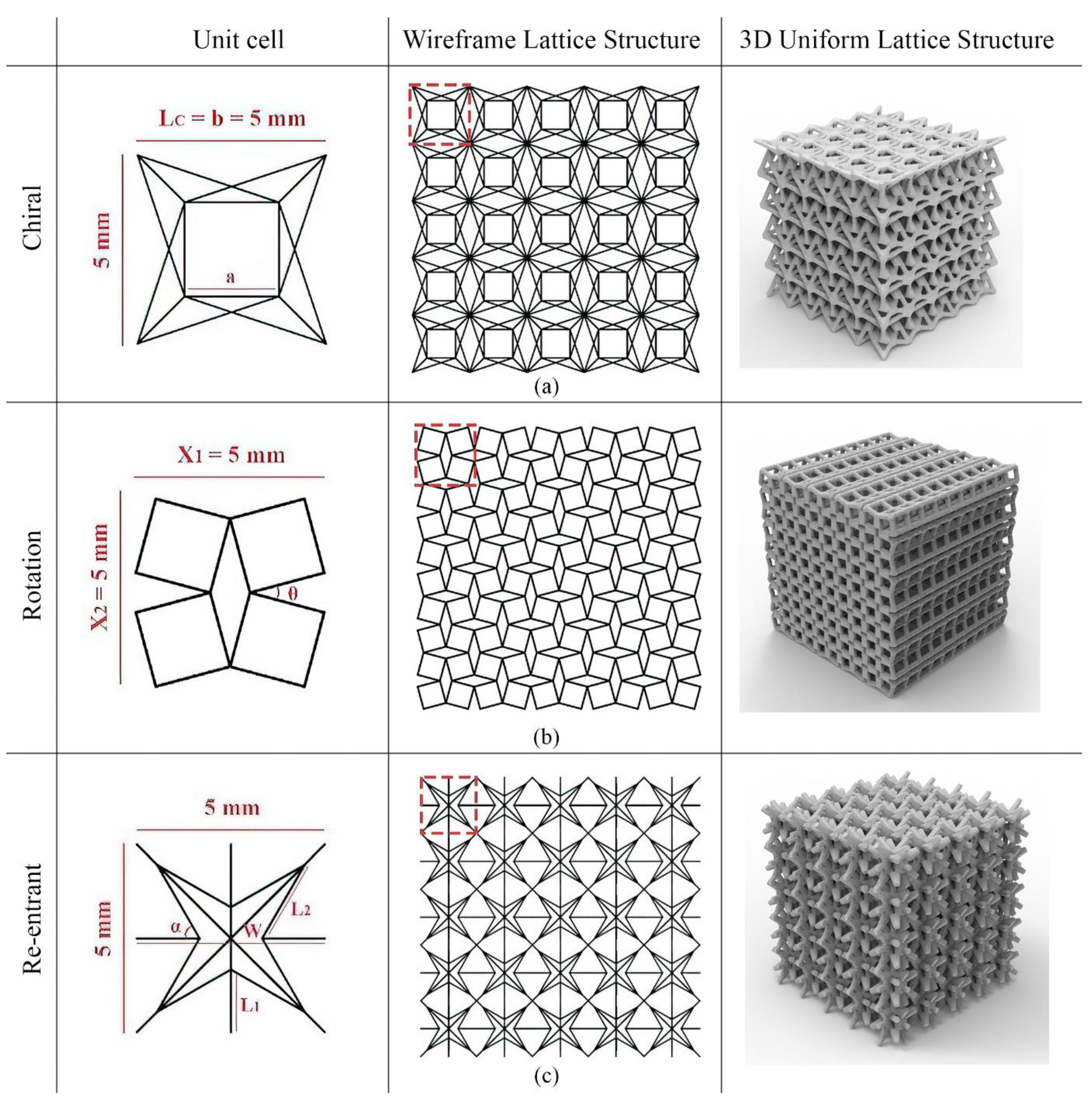
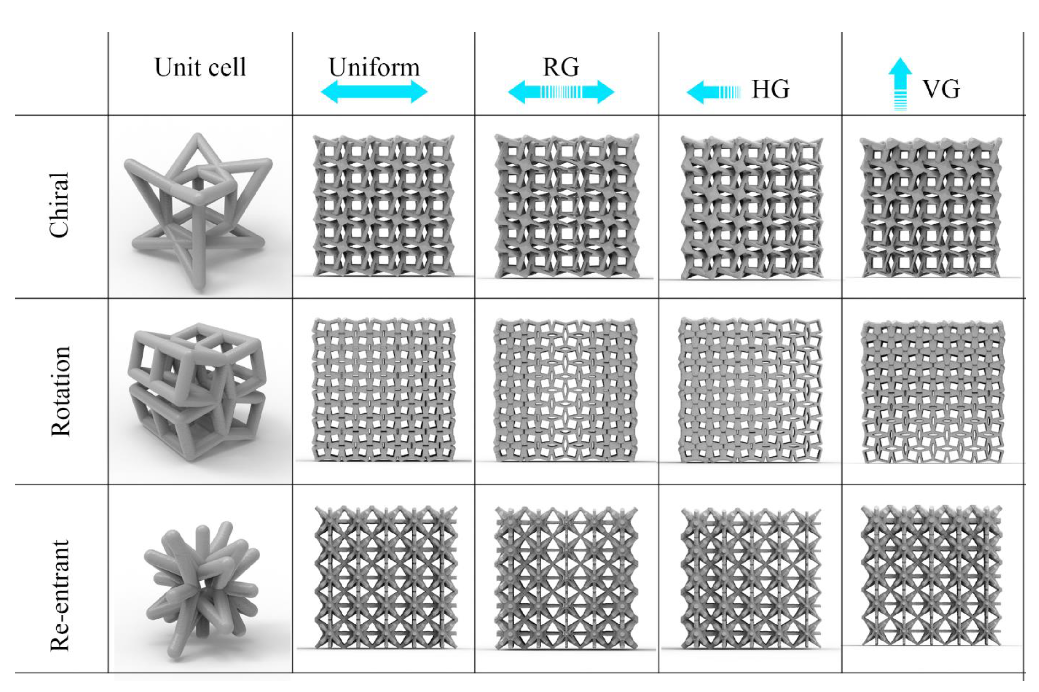
2.1. Design of Unit Cells and Lattice Structures

In this study, FGLSs with different configurations were designed using auxetic unit cells with advantages such as high energy absorption and impact resistance. Modified re-entrant star honeycomb, modified chiral and modified rotation unit cells were parametrically and knowledge-based modelled with dimensions of 5 × 5 × 5 mm in grasshopper. Two important features for the first of these unit cells, the re-entrant star honeycomb, are the re-entrant parts and the corners with hinge function. In the literature, the mechanism of this unit has been analysed assuming that the re-entrant parts and corners are elastically supported hinges where each element of the structure is modelled as a strut [43,44]. Star-shaped lattice structures have been extensively studied due to their attractive mechanical and physical properties such as negative Poisson’s ratio, low weight, high strength and high energy absorption. The star honeycomb unit cell chosen for this study was a simple model consisting of four straight beams of equal length (L1) joined by four re-entrant corners of equal length (L2) [45]. The corner angle between adjacent cell walls is denoted by α and the lattice constant is denoted by W (Figure 1c). Chen et al. (2018) reported the relationship between geometric parameters for the re-entrant star honeycomb unit cell (Equation (1)) [45]:
W = 2 × sin α 45 ° sin 45 ° × L 2 + L 1
The parameter settings for the re-entrant star honeycomb model: straight beam length L1 = 1.67 mm, re-entrant corner length L2 = 2.27 mm, corner angle α = 60° and lattice constant W = 5 mm. The re-entrant star honeycomb model, which is mostly used as a two-dimensional (2D) model in the literature, was converted into 3D by multiplying it in different axes and used as a unit cell in the design of lattice structures in this study.
Another cellular unit used in this study is the 3D chiral structure. Xu et al. (2022) proposed a new 3D chiral metamaterial that allows modular design [46]. The proposed chiral cellular unit consists of six independent units, useful for tailoring anisotropic chiral properties and combining unit cells with different geometries. In this study, for the 3D chiral unit, the prism length of the inner cube a, the edge length of the outer frame (b) and the outer edge length of the unit cell (Lc) are equalized, and the beams of the outer frame are extracted (Figure 1a).
The last unit cell used in this study was modified rotating squares. The rotating squares mechanism is one of the leading robust, feasible auxetic models [47]. The rotating square’s structure can easily turn corners when tensile force is applied. Due to its geometry, it can expand both upwards and downwards when under load [48,49]. Grima and Evans (2000) presented a detailed analysis of the relationships between rigid squares connected by hinges at the corners [48]. They expressed the size of the auxetic structure for a set of four connected squares, as shown in Equation (2). The auxetic rotating unit cell, which is mostly used in 2D in the literature, was converted to 3D in this study and used to form a lattice structure. The dimensions of X1 and X2 are both equal to 5 mm and the angle θ between the beams is 30° (Figure 1b).
X 1 = X 2 = 2 l   c o s θ 2 + s i n θ 2
The “intralattice” plugin of the grasshopper software was used for the design of the lattice structures in order to allow the unit cells to increase periodically. In this plugin, the customized unit cell designs created within the scope of this study have been added. FGLSs with uniform, vertically graded (VG), horizontally graded (HG) and radially graded (RG) configurations were created for each auxetic unit cell geometry (Figure 2).
The strut diameters of the cellular structures have a gradient structure ranging from 0.4 to 1 mm. The selection of these dimensions took into account the accuracy of the Stratasys Objet 30 Prime printer that was used in the production process. The strut diameters of the uniform structure were determined to be 0.7 mm by obtaining the arithmetic mean of the minimum and maximum strut diameters.

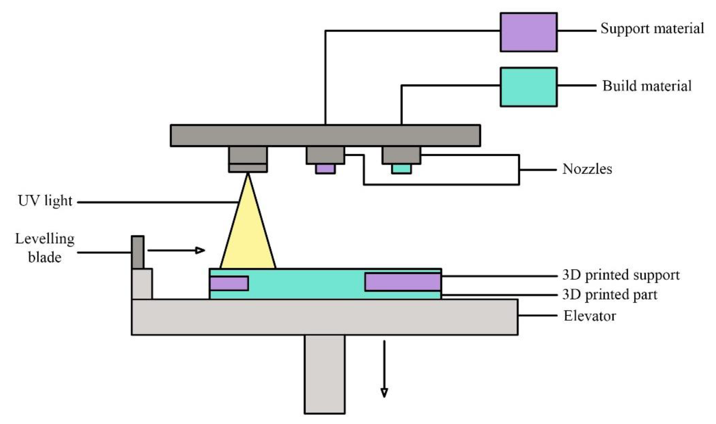
2.2. Additive Manufacturing of Lattice Structures with Material Jetting

The liquid photopolymer material was sprayed as droplets from the print heads and solidified via curing with the help of UV light in MJ (Figure 3). This process was repeated for each layer and the production process was completed [50]. MJ enabled the production of the highest layer thickness in the Z direction among all 3D printer systems. The most important advantage of this method was the production of parts with high dimensional accuracy and surface quality [51]. In this study, lattice structures were fabricated with semi-continuous acrylic based RGD720 photopolymer resin material using Stratasy Objet30 Prime working with MJ (Figure 4). The process parameters of the Objet30 Prime 3D printer are given in Table 1 [52]. Mechanical properties of the RGD720 photopolymer resin are given in Table 2 [53].

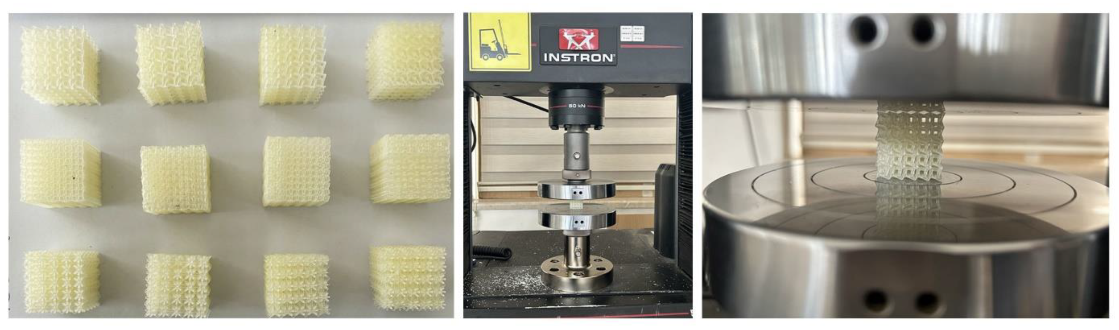
2.3. Compression Tests of Lattice Structures

As a result of the AM process, it was assumed that changes will occur in the mechanical properties of the 3D printed parts. Therefore, the mechanical properties of polymeric lattice structures were evaluated via compression tests. To characterize the compression behavior of the lattice structures, specimens were fabricated firstly with dimensions of 25 × 25 × 25 mm, in accordance with the standard for the Compression Testing of Rigid Cellular Plastics [54] (Figure 4). Mechanical tests were carried out with an Instron 5969 compression testing machine and the results were processed by a computer. To determine the strength properties of the lattice structures under load and to observe the effect of compression speed on mechanical behavior, the specimens were compressed 15 mm by applying a load of 50 kN at a 3 mm/min rate during the test.

3. Results and Discussions

In this section, the mechanical properties of the lattice structures of different configurations designed and fabricated are examined for their structural behavior, dimensional accuracy, relative density, deformation and displacement, compressive properties and energy absorption capabilities.

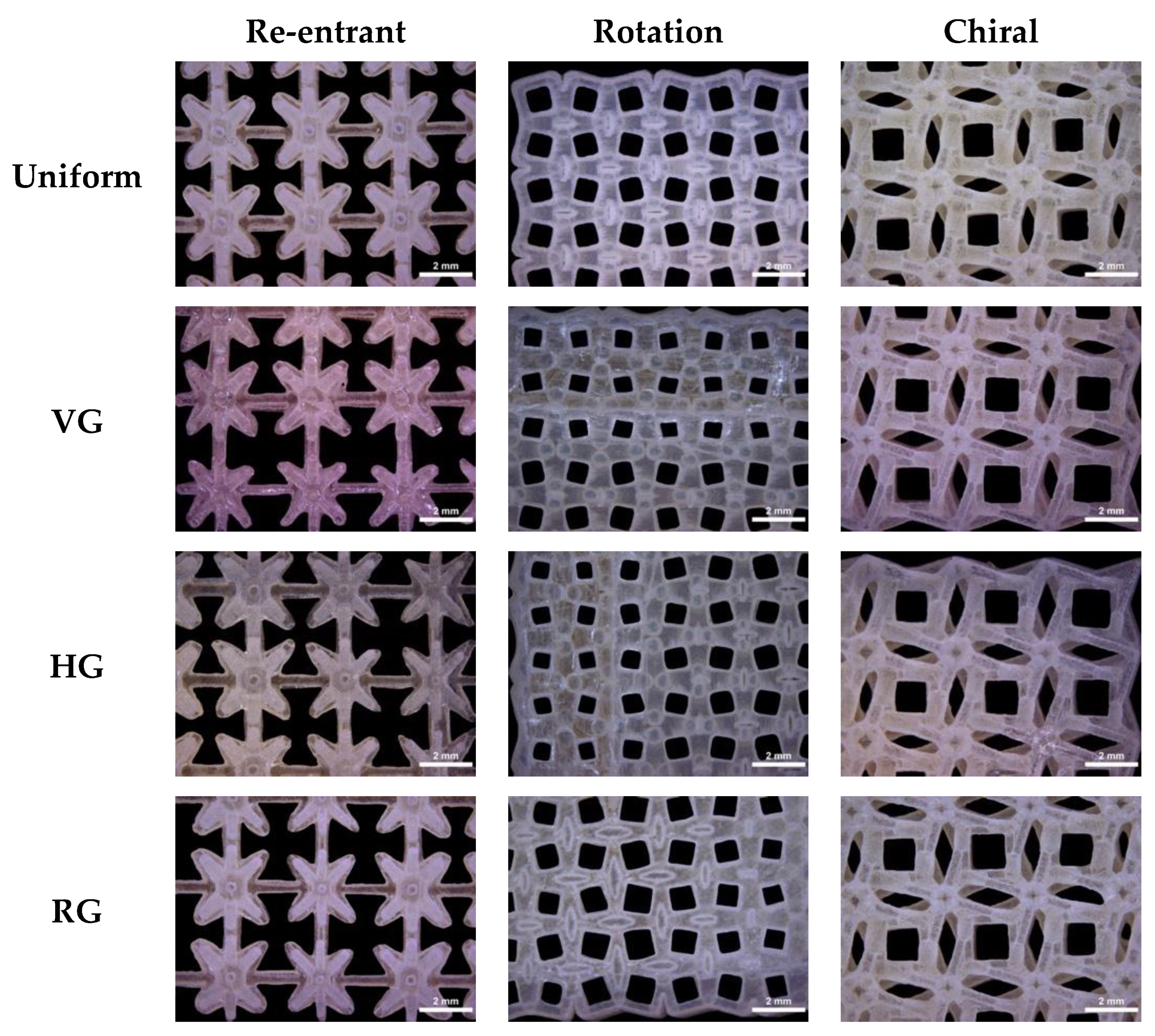
3.1. Structural Characteristics

3.1.1. Dimensional Accuracy

In order to determine the dimensional accuracy of the uniform lattice structures and FGLSs produced by MJ, all lattice structures were imaged with a Dino-Lite AM3113T Digital Microscope. The obtained values from the measurements are given in Table 3. The strut diameters of the lattice structures were measured from the top and bottom points with ImageJ® software for dimensional comparisons between CAD software and 3D printed struts (Figure 5).
As a result of the measurements, it was found that all strut diameters were larger than the CAD strut diameters. This was due to the lack of resolution of the support material used in MJ. For FGLSs graded from 0.4 mm to 1 mm strut diameter, it was observed that the difference between the CAD model and the printed specimens increased as the strut diameter decreased. In FGLSs, the maximum deviation at the minimum strut diameter, designed as 0.4 mm, was determined to be 18.5%, while the maximum deviation at the 1 mm strut diameter was determined to be 10.4%. The most important reason for the higher deviations for small strut diameters compared to large strut diameters is that the support material used during printing with MJ is more difficult to clean at small diameters. This suggests that thin structures are at greater risk of deflection due to incomplete dissolution of the support material.
It was observed that the dimensional deviation in uniform lattice structures was less than that in gradient structures. The largest deviation in the strut diameters of the uniform lattice structures was seen in the rotation lattice structure, with a deviation of 8.2%, while the lowest deviation was seen in the chiral structure, with a deviation of 5.4%. The lowest deviations between the strut diameters in FGLSs (between 3.4% and 9%) were obtained in chiral lattice structures. Thus, it was shown that the chiral lattice structure provides higher geometric accuracy. It was observed that the highest deviation among all strut diameter values was observed in the rotation lattice structure, with deviation values between 8.2% and 18.5%. In light of these evaluations, it can be said that the main factor that complicates the solution of the support material in rotating structures is CAD design.
In printing processes, the risk of defects is higher for thin structures and more careful finishing is required. The results show that the cleaning of support materials is still an important issue in the MJ method for high printing accuracy. Another consequence of this is that printed lattice structures are heavier than CAD designs (Table 3). Chiral structures are the heaviest lattice structures among both uniform and gradient structures.
According to the results obtained from microscopic images, the lattice structure that most meets the design expectations in terms of dimensional accuracy, geometry and strut connections are chiral structures. On the other hand, it was observed that the connections in the re-entrant structures are weaker than in the other structures. The reason for this is that the strut end connections cannot be formed strongly due to the star geometry in the re-entrant structure. As shown in Figure 5, in re-entrant lattice structures, the end connection of the star honeycombs could not be established; they were held only by body connections. Connection problems in cavity lattice structures also pose a problem in establishing specific geometric features during fabrication.

3.1.2. Relative Density

The relative density, denoted as ( ρ ¯ ), is determined as the ratio between the macroscopic density of a cellular solid ( ρ ) and the density of the base material ( ρ s ) . These are crucial parameters for understanding the mechanical properties of lattice structures, especially in terms of stiffness and strength [2].
ρ ¯ = ρ ρ s
Relative density is directly related to the porosity and the volume fraction of the material. As the relative density increases, the lattice structure generally becomes stiffer and stronger, but also heavier. On the contrary, as the relative density decreases, the structure becomes lighter, but can also become less stiff and weak. The values shown in Table 3 confirmed these descriptions. The measured relative densities for FGLSs are smaller for re-entrant structures than for other lattice designs. In addition, for re-entrant structures, the uniform configuration has been seen to have smaller relative densities than other configurations. The re-entrant structure has a lower relative density than the other structures, which is consistent with its low weight. The VG configuration of the chiral lattice structure has the highest relative density value. As seen in Equation (3), the relative density is directly related to the weight and volume of the structure. In this respect, it is consistent that the relative density is higher in the VG chiral lattice structure, which is a heavier structure than the other structures. The highest relative density among all specimens was found in the VG chiral lattice structure, followed by the VG rotation lattice structure.
Among all of the configurations, chirals have higher relative density values than other structures. The lowest relative density values were obtained for re-entrant structures. Except for the HG rotation lattice structure, uniform configurations have lower relative densities than gradient lattice structures. Uniform configurations have thinner strut diameters than FGLSs and the support material dissolves better than FGLSs, resulting in a lower relative density. Less material will result in less resistance to the applied force [9]. The relative density differences, which reduces the strength of the FGLS specimens discussed in Section 3.3, is also reflected in the mechanical strength values of the specimens.

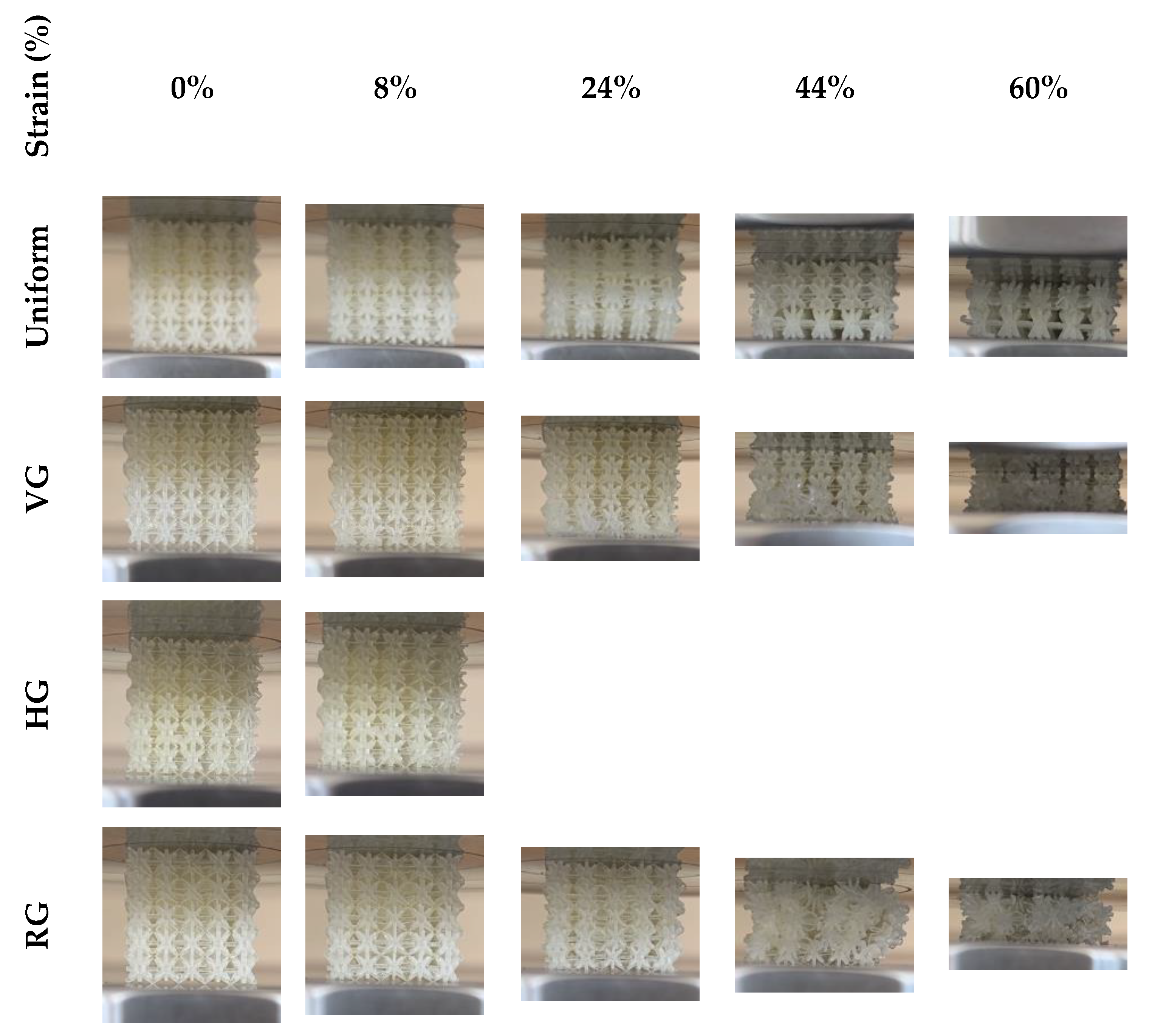
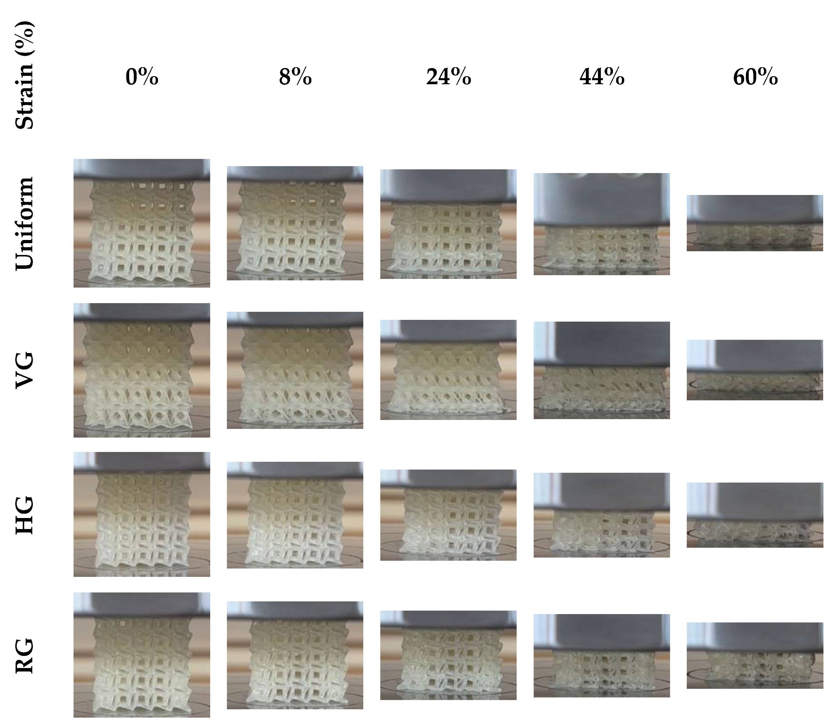
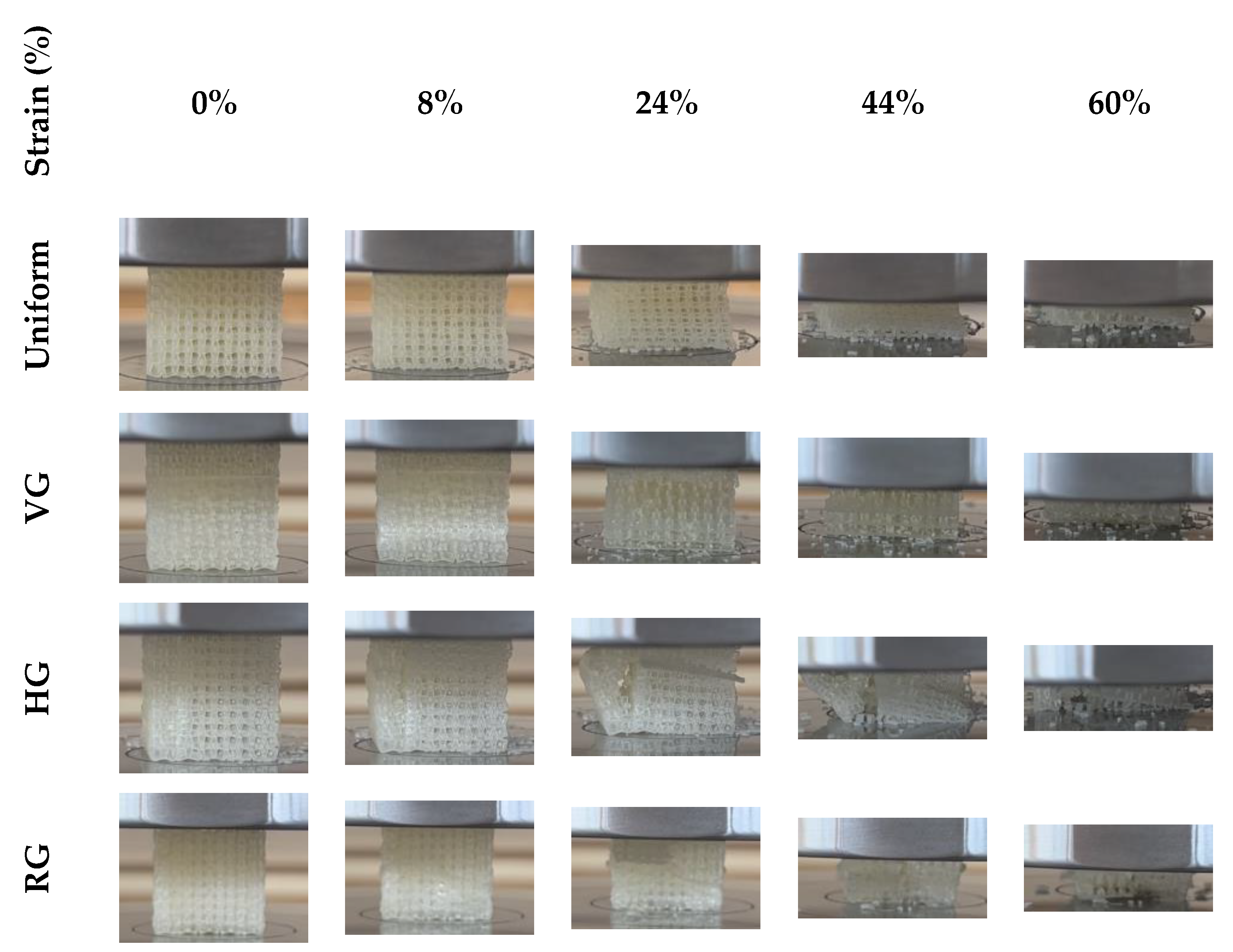
3.2. Deformation Behaviors

Deformation is the response of a material to stress or failure under external forces. The general behavior of lattice structures is evaluated using Maxwell’s criteria (M), specifically defined by the number of struts (s) and nodes (n) in the unit cell of the lattice (Equation (4) [55]. If M is less than 0, the number of struts in the lattice structure is insufficient to balance the bending moments at the nodes. In such cases, the struts are subjected to bending stresses and such structures are called “bending dominated”. On the other hand, if M is 0 or greater, the lattice is assumed to have a sufficient number of struts to balance the external forces [56]. These supports are primarily subjected to axial stresses and are referred to as “stretch dominated”. Stretch-dominated structures exhibit higher strength and stiffness than bending ones. Equation (4) is used to evaluate the spatial behavior of lattice structures:
M = s 3 n + 6
The deformation behavior of the 12 different lattice structures fabricated in this study is shown in Figure 6, Figure 7 and Figure 8. All designed structures were modified with additional struts. The calculations show that all of the structures in this study retained the bending-dominated structure, in accordance with the literature. The chiral unit cell had 16 nodes and 28 struts, while the rotation unit cell had 36 nodes and 60 struts and the re-entrant unit cell had 26 nodes and 42 struts. Therefore, the Maxwell numbers for the chiral, rotating and re-entrant unit cells were −14, −42 and −30, respectively, and bending was considered to be dominant. The bending-dominated properties of the lattice structures were also observed experimentally during compression tests. Figure 6, Figure 7 and Figure 8 show the deformation behavior of the test specimens at different strain rates during the compression test. The main crushing strength test showed similar behavior for chiral and re-entrant FGLSs, with densification occurring at around 50% strain. The rotation structure started to fracture and disintegrate after 24% strain and disintegrated at 60% strain, showing an utterly brittle material feature. The brittle structure is more evident in HG and RG structures. Chiral and re-entrant lattice structures showed ductile behavior in uniform and gradient structures. All chiral lattice structures showed high crushing strength in compression tests and were characterized by crashworthiness.
FGLSs deformations started in the thin strut layers and moved towards the thick strut layer. This was particularly evident in VG structures. The thin struts perpendicular to the load were displaced more, while the overlying thick layers stacked up towards the thin layer. As can be seen in Figure 6 and Figure 8, in VG specimens with chiral and re-entrant lattice structures, the high-density area remained intact, while the low-density area was damaged first. In re-entrant lattice structures, the underlying low-density region showed significant lateral expansion after damage. This means that the hardness varies in different density regions, which is different from the uniform lattice structure. In HG specimens, the geometry of the lattice structure was not disturbed in regions of high density. RG chiral and RG re-entrant lattice structures maintained their geometric integrity during the compression test. Chiral and re-entrant structures showed a typical flexural dominant deformation. In the HG configuration of the re-entrant structure, it was observed that the deformation did not continue after the first peak stress in compression. This is thought to be due to the faster transition of the struts in the re-entrant structure into the plastic region.
The shear bands were not observed ©n the uniform designs of the chiral and re-entrant structures during the compression test. The lattice structures showed similar densification stress under fracture force. This was consistent for chiral, rotation and re-entrant structures, which are known to be auxetic in the literature [57,58]. The rotation structure showed non-auxetic behavior at the mid-strain stage (ε ≥ 24%). This may be due to the use of modified unit cells in the lattice design. After the mid-strain stage (ε ≥ 24%), buckling of the specimens was observed, which ended with densification. Due to the strut diameter variations in the VG structures, the crushing process progressed from the upper high-density region to the lower low-density region until the structure was fully compacted. The deformation in the low-density region in the bottom layer was faster. Each layer collapse resulted in a linear stress increase and plateau, characteristic of ideal cellular solids. The shear bands were not observed in the FGLSs during the compression test. This can be explained by the collapse of thick layers into thin layers and is consistent with the literature [59,60].

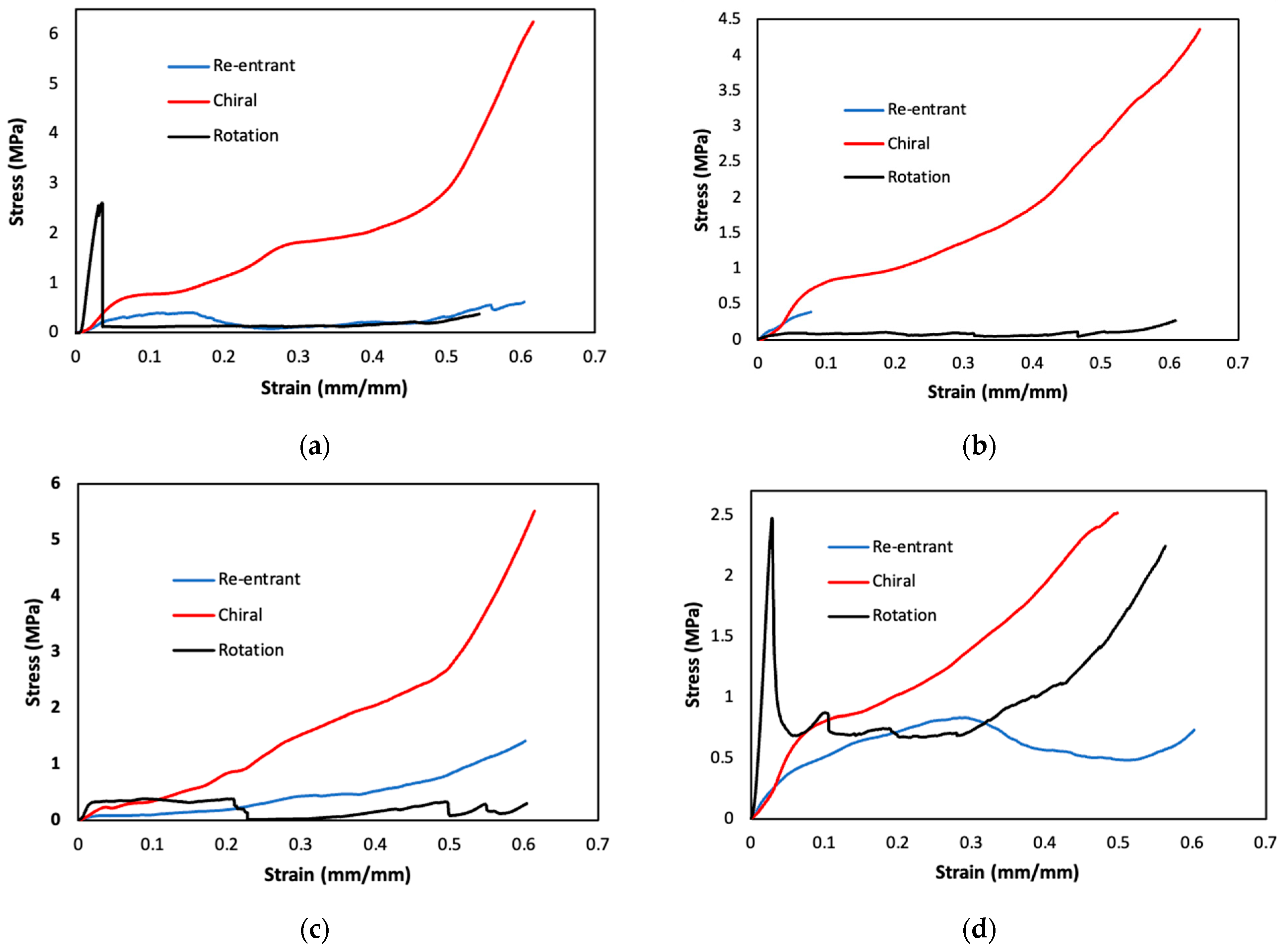
3.3. Compressive Properties

In this section, the results of compression tests carried out to investigate the mechanical properties of lattice structures are analysed. The reactions and deformation processes of lattice structures during compression testing reveal their load-carrying ability and energy absorption properties. During the compression test, 12 different specimens were compressed by 15 mm by applying a 50 kN load at a speed of 3 mm/min.
Young’s modulus, compressive strain, energy absorption and specific energy absorption values were calculated using the maximum compressive stress and extension (L) values obtained from the test and shown in Table 4. At each stage of the compression test, the tester calculated the compressive stress in the specimen to determine the maximum stress (σ) and strain ( L ) [61]. The strain value was calculated using Equation (5).
ε = L L 0
where L0 and L represent the original length of the specimen and the change in length, respectively. Young’s modulus © is the measurement of the elastic deformation of the material under force [51]. Young’s modulus is calculated analytically from the slope of the linear elastic region of the stress (σ)–strain (ε) curve. The elastic modulus was calculated using Equation (6) and the results are shown in Table 4.
E = σ ε

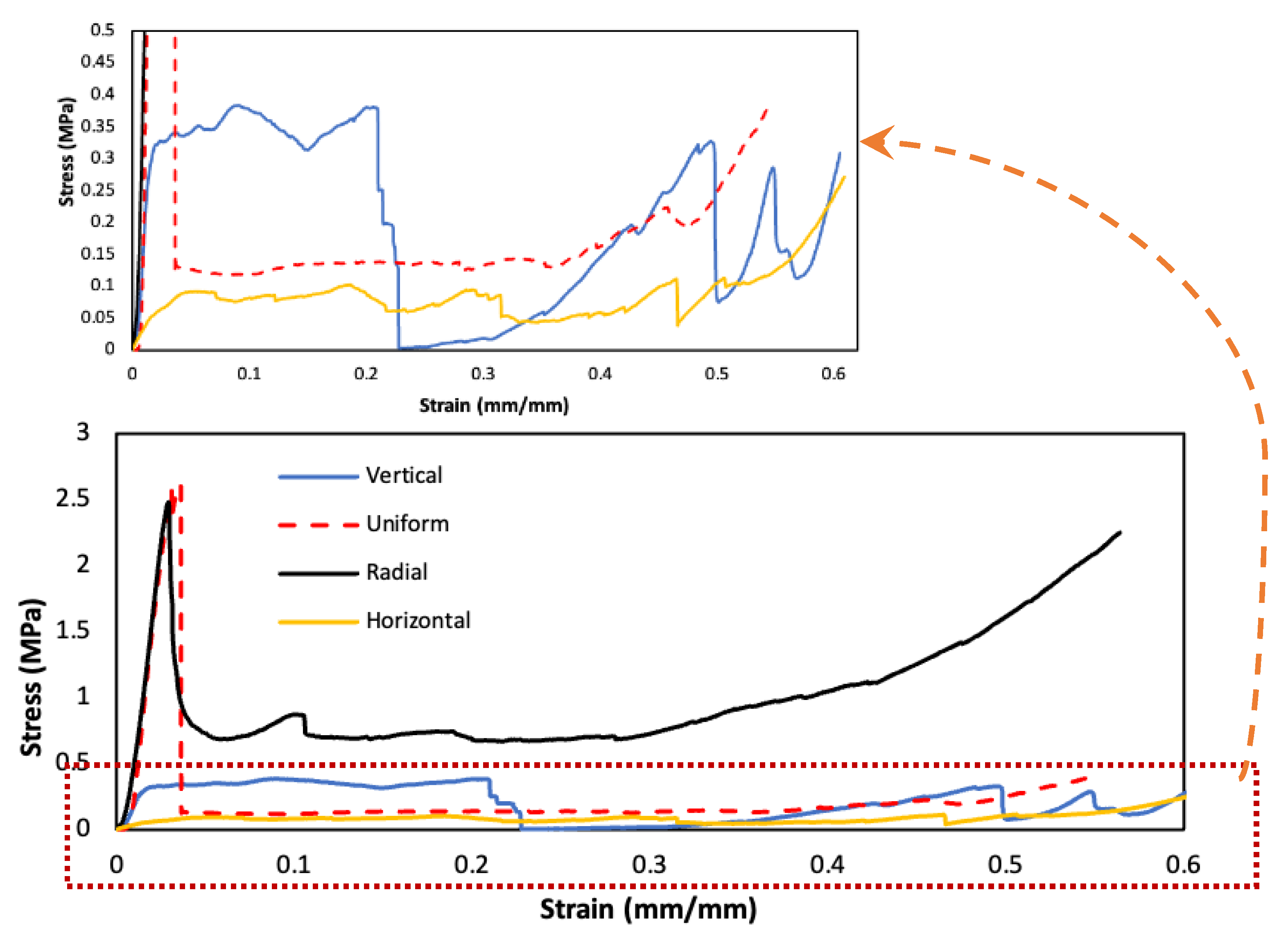
3.3.1. Compressive Test Results for Chiral Structures

According to the compression test results, the highest compressive stress (0.85715 Mpa) in the chiral structures occurred in the HG specimen. The maximum compressive stress of the uniform specimen was 0.81773 Mpa, while the compressive stress of the RG specimens was 0.8067 Mpa. The lowest compressive stress (0.22529 Mpa) in chiral lattice structures occurred in the VG specimens. The highest elastic modulus was observed in the RG specimen, while the Young modulus of the uniform specimen was lower than the elastic modulus of the HG and RG specimens (Table 4). The compressive stress of the VG specimen was 72.4% lower than the uniform specimen, while the elastic modulus was only 3.5% lower.
Hence, the strain value of the VG specimen (ε = 0.0376) was very low compared to the other specimens. From the stress–strain curve in Figure 9, the low-density region in the bottom layer of the VG specimen deformed rapidly. This rapid deformation caused the specimen to reach maximum stress at a very small strain rate. The reason is that the elastic modulus is relatively higher than the other structures. The fact that the elastic modulus of the horizontal (7.2848 Mpa) and radially graded specimens (7.3443 Mpa) in the chiral design were higher than the uniform specimens (6.0109 Mpa) indicates that the gradient structure provided a more balanced load distribution.

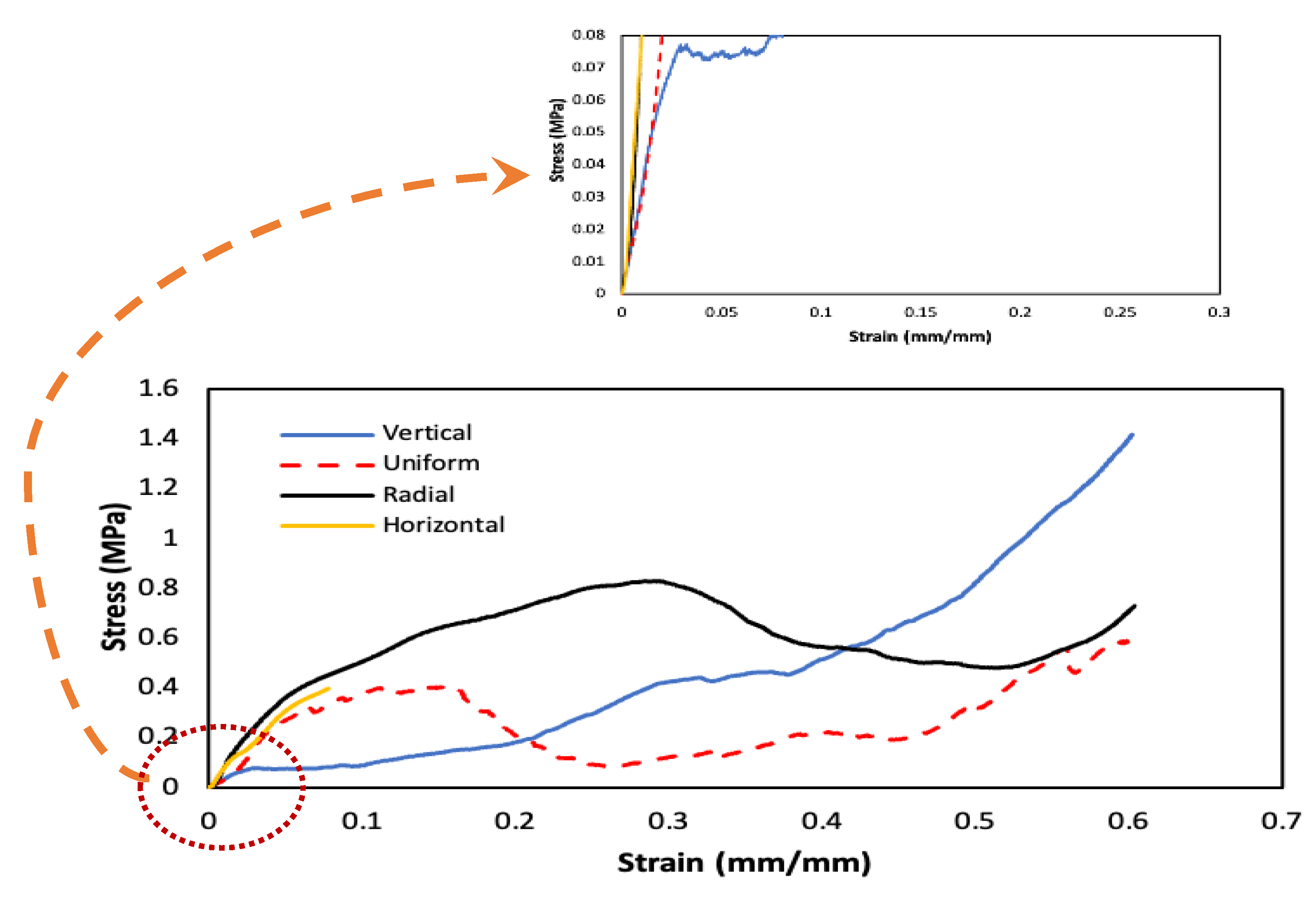
3.3.2. Compressive Test Results for Re-Entrant Structures

The highest compressive stresses in re-entrant structures were observed in RG (0.83003 Mpa) and uniform (0.40694 Mpa) specimens. As seen in Table 4, the RG specimen carried higher stresses than the other configurations in the re-entrant lattice structure. On the other hand, the elastic modulus of the RG specimen was 76% lower than that of the HG configuration and was very close to the other combinations because it reached its maximum stress at a higher strain (ε = 0.2852). The HG specimen reached a maximum stress value of 0.39785 Mpa at a very low strain value (ε = 0.077) compared to the RG specimen. The HG specimen fractured without densification at very low strain values (Figure 10). This may be due to the weak connection characteristic of the re-entrant structure. The lowest maximum stress and elastic modulus in the re-entrant structures were found in the VG specimen, with 0.07614 Mpa and 2.4837 Mpa, respectively (Table 4). The maximum compressive stress value of the uniform specimen was 51.8% lower than that of the RG specimen, while the elastic modulus was 11.5% lower. This was due to the relatively high tensile value of the RG specimen. The RG specimen had higher stresses in the plateau and densification regions, resulting in a higher toughness value. This is also reflected in the energy absorption property discussed in the next section. Observations in the tests confirmed that in each configuration, the maximum stresses were seen in the collapse of layers in the lattice structure, with the layer with the thinnest supports collapsing first.

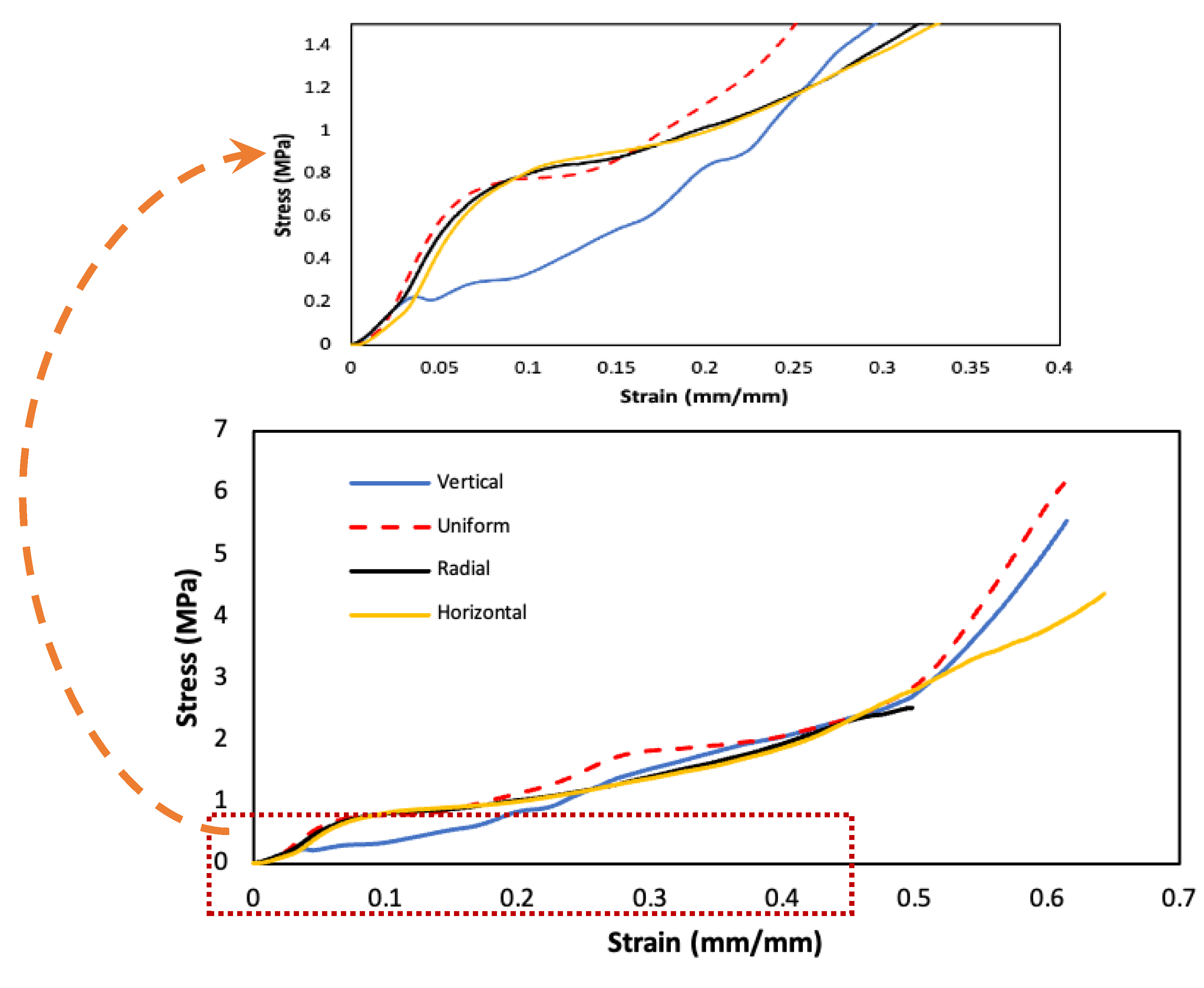
3.3.3. Compressive Test Results for Rotation Structures

In the rotation lattice structures, the uniform and RG specimens outperformed the other specimens in terms of both first compressive strength and elastic modulus (Figure 11). This indicates that these two configurations allow a more effective load distribution on the lattice.
According to the compression test results, the highest compressive stress and elastic modulus values are obtained in the rotation structure (Figure 12a,d). Maximum Young’s modulus values were obtained in the uniform and radial configurations of the rotation structure. This is due to the fact that these two configurations reach high compressive stress values at very low strain values.
The greater strength of the rotation structure compared to the other structures resulted in high compressive stress, while the brittle material properties resulted in a low strain value. FGLSs were seen to have the highest mechanical strength values among all of the lattices. Therefore, FGLSs gave the best results for the elastic modulus. The lowest mechanical strength and strain values were observed in the VG specimens (Figure 12c).
The results show that the gradient structure provides a more balanced load distribution. As seen Figure 12, although the mechanical strength and elastic modulus results obtained with the chiral structure were worse than the rotation structure, the ductile material property was reflected in the strain values. This was also reflected in the energy absorption capacity of the chiral structure.

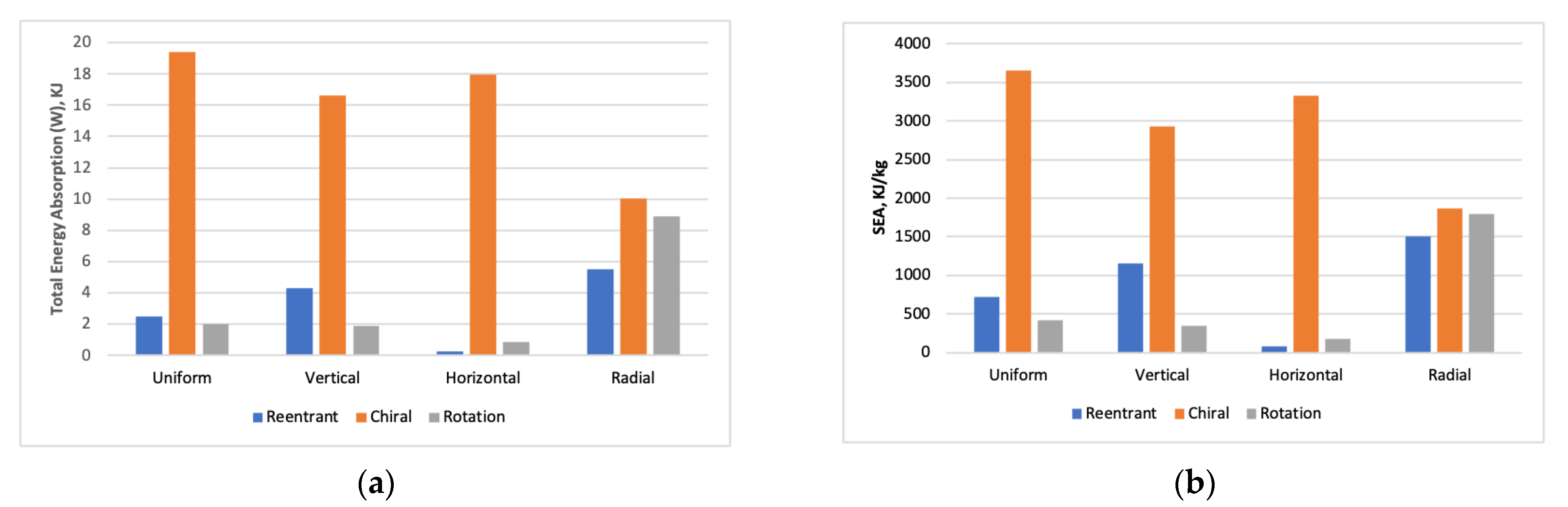
3.4. Energy Absorption Capabilities

The energy absorption behavior of a structure refers to its ability to dissipate energy without experiencing any failure, especially during impact or deformation. Energy is usually converted into other forms, such as plastic deformation, without causing the material or structure to fracture or shatter. The lattices deform significantly due to their high porosity. To evaluate the energy absorption capacity of lattice structures, it is necessary to define the relevant parameters. Energy absorption per unit volume (W) is the most commonly used way to represent the energy absorption capacity (Equation (7)) [17]:
W = 0 ε d σ ε d ε
where ε d   is the maximum strain and σ and ε represent the compressive stress and strain, respectively. The value of energy absorption per unit volume is the area enclosed by the stress–strain curve and the strain axis. Specific Energy Absorption (SEA) is defined as the sum of energy absorbed per unit mass [62]. It is calculated as total energy absorption (W) divided by mass (m) (Equation (8):
S E A = W m
Table 4 shows the total energy absorption (W) and SEA values of the lattice structures. The total energy absorption of RG configurations is high in all lattice structures except the chiral structure. For the RG configurations of FGLSs, an energy absorption of 5.505 KJ was found in the re-entrant specimen and 8.907 KJ in the rotation specimen. This indicates that the internal microstructure design of the RG configuration can absorb energy more effectively.
As shown in Figure 13a, the best total energy absorption results in all combinations were obtained in the chiral structure. In the chiral structure, the uniform lattice has the highest energy absorption. It was followed by the horizontal graded structure with only 7% lower energy absorption. Among all of the structures, the highest energy absorption was obtained in chiral structures. Although the uniform chiral lattice has the highest energy absorption, FGLSs generally performed well in terms of energy absorption. The best SEA performance was also obtained with chiral structures (Figure 13b). These results indicate that chiral designs would give good results in applications where high toughness and energy absorption would be expected.
The fact that RG structures have better energy absorption capabilities than uniform structures in rotation and re-entrant structures shows the energy absorption potential of FGLSs. These results can be further improved by making modifications to the unit cell designs. Re-entrant lattice structures, which have weaker compressive strength values than other structures, show a better energy absorption performance. This indicates that such designs have a high energy absorption potential. Although the re-entrant structure had a weak first compressive stress value, its high energy absorption performance indicates that the energy absorption capacity of this design is more critical than the compressive strength.
The results obtained for lattice with different configurations designed within the scope of this study show that the internal design (cell model) of the structures is decisive in obtaining a more ideal energy-absorbing structure in line with the literature [63]. The maximum energy absorption capacity value (19.381 KJ) and the maximum SEA value (3649.905 KJ/kg) were obtained in the uniform configuration of the chiral lattice structure. This was due to the high strain value of the uniform configuration of the chiral structure, as well as the high compressive stress peak values in the plateau region. Nevertheless, the energy absorption values of the HG and VG specimens in the chiral structures were only 7.3% and 14.2% lower, respectively, than the uniform structure. This indicates that the performance of FGLSs with chiral structures can potentially be improved. As a result, when all designs were evaluated, the chiral lattice structure was advantageous compared to other designs in terms of total and specific energy absorption.

4. Conclusions

In this study, horizontal, vertical and radially graded lattice structures were compared with uniform structures in terms of deformation behavior, mechanical properties and energy absorption. The main conclusions were obtained as follows:
  • According to the results of the compression test performed in this study, the highest compressive strength value was obtained in the uniform configuration of the rotation lattice structure. When only FGLSs are considered, the best results were obtained in the RG configuration of the rotation lattice structure. The HG and RG configurations of the chiral lattice structure stand out for their high energy absorption.
  • It was found that the energy absorption capacities of rotating and re-entrant FGLSs were more successful than those of uniform structures. The energy absorption potentials of FGLSs in chiral lattice structures can be further enhanced with improvements to the design.
  • It was found that the dimensional deviation in uniform lattice was less than that in gradient lattice. The chiral structure was superior in geometric accuracy and dimensional completeness.
  • The problem of the incomplete dissolution of the support material, which occurs in the post-production process with MJ, leads to dimensional deviations, especially in thin geometries. Therefore, the largest geometric deviations occurred in thin geometries. CAD design has an impact on dimensional accuracy, which complicates the solution of the support material in rotation lattice.
  • The connection problems in the re-entrant lattice structure showed that geometric features can cause problems during fabrication. This was due to the inability to create strong strut-end connections in the re-entrant structure.
  • Consistent with the literature [63], the results showed that the internal design of lattice structures is decisive in achieving a more ideal energy-absorbing structure.
  • The maximum energy absorption capacity value (19.381 KJ) and the maximum SEA value (3649.905 KJ/kg) were obtained from the uniform configuration of the chiral lattice structure.
  • Generally, the best SEA performance was obtained for chiral structures. The results showed that chiral lattice structures can be used for applications where high toughness and energy dissipation are expected.
  • This study shows that FGLSs have significant advantages over uniform structures in terms of dimensional accuracy, mechanical strength and energy absorption and demonstrates the potential of these structures for industrial applications.

Author Contributions

Conceptualization, N.T. and İ.Ş.; investigation, N.T., İ.Ş. and H.G.; validation, data analysis, İ.Ş., N.T. and H.G.; writing—original draft preparation, N.T. and İ.Ş.; writing—review and editing, H.G. and N.T.; supervision, İ.Ş. and H.G. All authors have read and agreed to the published version of the manuscript.

Funding

This research was funded by Gazi University Scientific Research Projects Unit, Turkey (Grant No.: FGA-2023-8673).

Institutional Review Board Statement

Not applicable.

Informed Consent Statement

Not applicable.

Data Availability Statement

Data are included in the article. Additional data are available by contacting the author.

Acknowledgments

We would like to thank Başaran Yenilikçi Teknolojiler San. Ve Tic. Ltd. Şti. for supporting the 3D printing process of the samples.

Conflicts of Interest

The authors declare no conflict of interest.

References

  1. Hou, W.; Yang, X.; Zhang, W.; Xia, Y. Design of energy-dissipating structure with functionally graded auxetic cellular material. Int. J. Crashworthiness 2018, 23, 366–376. [Google Scholar] [CrossRef]
  2. Tancogne-Dejean, T.; Spierings, A.B.; Mohr, D. Additively-manufactured metallic micro-lattice materials for high specific energy absorption under static and dynamic loading. Acta Mater. 2016, 116, 14–28. [Google Scholar] [CrossRef]
  3. Handler, E.; Sterling, A.; Pegues, J.; Ozdes, H.; Masoomi, M.; Shamsaei, N.; Thompson, S.M. Design and process considerations for effective additive manufacturing of heat exchangers. In Proceedings of the 2017 International Solid Freeform Fabrication Symposium, Austin, TX, USA, 7–9 August 2017. [Google Scholar]
  4. Pan, G.T.; Chong, S.; Tsai, H.J.; Lu, W.H.; Yang, T.C.K. The effects of iron, silicon, chromium, and aluminium additions on the physical and mechanical properties of recycled 3D printing filaments. Adv. Polym. Technol. 2018, 37, 1176–1184. [Google Scholar] [CrossRef]
  5. Köhnen, P.; Haase, C.; Bültmann, J.; Ziegler, S.; Schleifenbaum, J.H.; Bleck, W. Mechanical properties and deformation behavior of additively manufactured lattice structures of stainless steel. Mater. Des. 2018, 145, 205–217. [Google Scholar] [CrossRef]
  6. Chen, Z.; Wang, Z.; Zhou, S.; Shao, J.; Wu, X. Novel negative Poisson’s ratio lattice structures with enhanced stiffness and energy absorption capacity. Materials 2018, 11, 1095. [Google Scholar] [CrossRef]
  7. Pan, C.; Han, Y.; Lu, J. Design and optimization of lattice structures: A review. Appl. Sci. 2020, 10, 6374. [Google Scholar] [CrossRef]
  8. Loh, G.H.; Pei, E.; Harrison, D.; Monzón, M.D. An overview of functionally graded additive manufacturing. Addit. Manuf. 2018, 23, 34–44. [Google Scholar] [CrossRef]
  9. Choy, S.Y.; Sun, C.N.; Leong, K.F.; Wei, J. Compressive properties of functionally graded lattice structures manufactured by selective laser melting. Mater. Des. 2017, 131, 112–120. [Google Scholar] [CrossRef]
  10. Miyamoto, Y.; Kaysser, W.A.; Rabin, B.H.; Kawasaki, A.; Ford, R.G. Functionally Graded Materials: Design, Processing and Applications; Springer Science & Business Media: New York, NY, USA, 2013; Volume 5, pp. 29–63. [Google Scholar]
  11. Khan, S. Analysis of tribological applications of functionally graded materials in mobility engineering. Int. J. Sci. Eng. Res. 2015, 6, 1150–1160. [Google Scholar]
  12. Niendorf, T.; Leuders, S.; Riemer, A.; Brenne, F.; Tröster, T.; Richard, H.A.; Schwarze, D. Functionally graded alloys obtained by additive manufacturing. Adv. Eng. Mater. 2014, 16, 857–861. [Google Scholar] [CrossRef]
  13. Xu, Z.; Razavi, S.M.J.; Ayatollahi, M.R. Functionally Graded Lattice Structures: Fabrication Methods, Mechanical Properties, Failure Mechanisms and Applications. Int. J. Impact Eng. 2022, 125, 163–172. [Google Scholar]
  14. Schumacher, C.; Bickel, B.; Rys, J.; Marschner, S.; Daraio, C.; Gross, M. Microstructures to control elasticity in 3D printing. ACM Trans. Graph. (TOG) 2015, 34, 136. [Google Scholar] [CrossRef]
  15. Zhang, W.; Ma, Z.; Hu, P. Mechanical properties of a cellular vehicle body structure with negative Poisson’s ratio and enhanced strength. J. Reinf. Plast. Compos. 2014, 33, 342–349. [Google Scholar] [CrossRef]
  16. Maskery, I.; Hussey, A.; Panesar, A.; Aremu, A.; Tuck, C.; Ashcroft, I.; Hague, R. An investigation into reinforced and functionally graded lattice structures. J. Cell. Plast. 2017, 53, 151–165. [Google Scholar] [CrossRef]
  17. Bai, L.; Gong, C.; Chen, X.; Sun, Y.; Xin, L.; Pu, H.; Peng, Y.; Luo, J. Mechanical properties and energy absorption capabilities of functionally graded lattice structures: Experiments and simulations. Int. J. Mech. Sci. 2020, 182, 105735. [Google Scholar] [CrossRef]
  18. Takezawa, A.; Zhang, X.; Kato, M.; Kitamura, M. Method to optimize an additively-manufactured functionally-graded lattice structure for effective liquid cooling. Addit. Manuf. 2019, 28, 285–298. [Google Scholar] [CrossRef]
  19. Plocher, J.; Panesar, A. Mechanical performance of additively manufactured fiber-reinforced functionally graded lattices. JOM 2020, 72, 1292–1298. [Google Scholar] [CrossRef]
  20. Al-Saedi, D.S.; Masood, S.H.; Faizan-Ur-Rab, M.; Alomarah, A.; Ponnusamy, P. Mechanical properties and energy absorption capability of functionally graded F2BCC lattice fabricated by SLM. Mater. Des. 2018, 144, 32–44. [Google Scholar] [CrossRef]
  21. Novak, N.; Vesenjak, M.; Ren, Z. Auxetic cellular materials-a review. Stroj. Vestn. J. Mech. Eng. 2016, 62, 485–493. [Google Scholar] [CrossRef]
  22. Li, C.; Shen, H.S.; Wang, H.; Yu, Z. Large amplitude vibration of sandwich plates with functionally graded auxetic 3D lattice core. Int. J. Mech. Sci. 2020, 174, 105472. [Google Scholar] [CrossRef]
  23. Qiao, J.X.; Chen, C.Q. Impact resistance of uniform and functionally graded auxetic double arrowhead honeycombs. Int. J. Impact Eng. 2015, 83, 47–58. [Google Scholar] [CrossRef]
  24. Aremu, A.O.; Brennan-Craddock, J.P.J.; Panesar, A.; Ashcroft, I.A.; Hague, R.J.; Wildman, R.D.; Tuck, C. A voxel-based method of constructing and skinning conformal and functionally graded lattice structures suitable for additive manufacturing. Addit. Manuf. 2017, 13, 1–13. [Google Scholar] [CrossRef]
  25. Daynes, S.; Feih, S.; Lu, W.F.; Wei, J. Optimisation of functionally graded lattice structures using isostatic lines. Mater. Des. 2017, 127, 215–223. [Google Scholar] [CrossRef]
  26. Nguyen, C.H.P.; Choi, Y. Concurrent density distribution and build orientation optimization of additively manufactured functionally graded lattice structures. Comput. Aided Des. 2020, 127, 102884. [Google Scholar] [CrossRef]
  27. Nguyen, C.H.P.; Kim, Y.; Choi, Y. Design for additive manufacturing of functionally graded lattice structures: A design method with process induced anisotropy consideration. Int. J. Precis. Eng. Manuf. Green Technol. 2021, 8, 29–45. [Google Scholar] [CrossRef]
  28. Yi, B.; Zhou, Y.; Yoon, G.H.; Saitou, K. Topology optimization of functionally-graded lattice structures with buckling constraints. Comput. Methods Appl. Mech. Eng. 2019, 354, 593–619. [Google Scholar] [CrossRef]
  29. Mora, S.; Pugno, N.M.; Misseroni, D. 3D printed architected lattice structures by material jetting. Mater. Today 2022, 59, 107–132. [Google Scholar] [CrossRef]
  30. Gülcan, O.; Günaydın, K.; Tamer, A. The state of the art of material jetting—A critical review. Polymers 2021, 13, 2829. [Google Scholar] [CrossRef]
  31. Meteyer, S.; Xu, X.; Perry, N.; Zhao, Y.F. Energy and material flow analysis of binder-jetting additive manufacturing processes. Procedia CIRP 2014, 15, 19–25. [Google Scholar] [CrossRef]
  32. Golhin, A.P.; Srivastava, C.; Strandlie, A.; Sole, A.S.; Grammatikos, S. Effects of accelerated aging on the appearance and mechanical performance of materials jetting products. Mater. Des. 2023, 228, 111863. [Google Scholar] [CrossRef]
  33. Hao, W.; Liu, J.; Kanwal, H. Compressive properties of cementitious composites reinforced by 3D printed PA 6 lattice. Polym. Test. 2023, 117, 107811. [Google Scholar] [CrossRef]
  34. Tee, Y.L.; Tran, P.; Leary, M.; Pille, P.; Brandt, M. 3D Printing of polymer composites with material jetting: Mechanical and fractographic analysis. Addit. Manuf. 2020, 36, 101558. [Google Scholar] [CrossRef]
  35. Wang, Z.; Bo, R.; Bai, H.; Cao, S.; Wang, S.; Chang, J.; Lan, Y.; Li, Y.; Zhang, Y. Flexible Impact-Resistant Composites with Bioinspired Three-Dimensional Solid–Liquid Lattice Designs. ACS Appl. Mater. Interfaces 2023, 15, 22553–22562. [Google Scholar] [CrossRef] [PubMed]
  36. Guo, X.; Hu, Y.; Li, X.; Fuh, J.Y.H.; Lu, W.F. 3D printing microlattice interpenetrating phase composites for energy absorption, damage resistance, and fracture toughness. Compos. Struct. 2023, 325, 117617. [Google Scholar] [CrossRef]
  37. Thirunavukkarasu, N.; Gao, J.; Peng, S.; Laroui, A.; Wu, L.; Weng, Z. Mechanically robust 3D printed elastomeric lattices inspired by strong and tough hierarchical structures. Addit. Manuf. 2023, 66, 103451. [Google Scholar] [CrossRef]
  38. Veloso, F.; Gomes-Fonseca, J.; Morais, P.; Correia-Pinto, J.; Pinho, A.C.; Vilaça, J.L. Overview of methods and software for the design of functionally graded lattice structures. Adv. Eng. Mater. 2022, 24, 2200483. [Google Scholar] [CrossRef]
  39. Dangal, B.; Jung, S. The Impact of Additive Manufacturing Constraints and Design Objectives on Structural Topology Optimization. Appl. Sci. 2023, 13, 10161. [Google Scholar] [CrossRef]
  40. Duarte, I.; Vesenjak, M.; Krstulović-Opara, L.; Ren, Z. Static and dynamic axial crush performance of in-situ foam-filled tubes. Compos. Struct. 2015, 124, 128–139. [Google Scholar] [CrossRef]
  41. Vesenjak, M.; Hokamoto, K.; Matsumoto, S.; Marumo, Y.; Ren, Z. Uni-directional porous metal fabricated by rolling of copper sheet and explosive compaction. Mater. Lett. 2016, 170, 39–43. [Google Scholar] [CrossRef]
  42. Vesenjak, M.; Kovačič, A.; Tane, M.; Borovinšek, M.; Nakajima, H.; Ren, Z. Compressive properties of lotus-type porous iron. Comput. Mater. Sci. 2012, 65, 37–43. [Google Scholar] [CrossRef]
  43. Milton, G.W. Composite materials with Poisson’s ratios close to—1. J. Mech. Phys. Solids 1992, 40, 1105–1137. [Google Scholar] [CrossRef]
  44. Grima, J.N.; Gatt, R.; Alderson, A.; Evans, K.E. On the potential of connected stars as auxetic systems. Mol. Simul. 2005, 31, 925–935. [Google Scholar] [CrossRef]
  45. Chen, M.; Jiang, H.; Zhang, H.; Li, D.; Wang, Y. Design of an acoustic superlens using single-phase metamaterials with a star-shaped lattice structure. Sci. Rep. 2018, 8, 1861. [Google Scholar] [CrossRef] [PubMed]
  46. Xu, W.; Liu, Z.; Wang, L.; Zhu, P. 3D chiral metamaterial modular design with highly-tunable tension-twisting properties. Mater. Today Commun. 2022, 30, 103006. [Google Scholar] [CrossRef]
  47. Chen, Z.; Wu, X.; Xie, Y.M.; Wang, Z.; Zhou, S. Re-entrant auxetic lattices with enhanced stiffness: A numerical study. Int. J. Mech. Sci. 2020, 178, 105619. [Google Scholar] [CrossRef]
  48. Grima, J.N.; Evans, K.E. Auxetic behavior from rotating squares. J. Mater. Sci. Lett. 2000, 19, 1563–1565. [Google Scholar] [CrossRef]
  49. Plewa, J.; Płońska, M.; Lis, P. Investigation of modified auxetic structures from rigid rotating squares. Materials 2022, 15, 2848. [Google Scholar] [CrossRef]
  50. Moore, J.P.; Williams, C.B. Fatigue properties of parts printed by PolyJet material jetting. Rapid Prototyp. J. 2015, 21, 675–685. [Google Scholar] [CrossRef]
  51. Eren, O.; Sezer, H.K.; Yalçın, N. Effect of lattice design on mechanical response of PolyJet additively manufactured cellular structures. J. Manuf. Process. 2022, 75, 1175–1188. [Google Scholar] [CrossRef]
  52. Objet30 Series Specifications. Available online: https://proto3000.com/product/objet30-series/#Specifications (accessed on 12 October 2023).
  53. RGD720 Rigid Translucent Photosensitive Resin Data Sheet. Available online: https://www.stratasys.com/materials/search/rgd720 (accessed on 1 June 2023).
  54. ASTM D1621. Standard Test Method for Compressive Properties of Rigid Cellular Plastics. ASTM International: West Conshohocken, PA, USA, 2000. [CrossRef]
  55. Alghamdi, A.; Maconachie, T.; Downing, D.; Brandt, M.; Qian, M.; Leary, M. Effect of additive manufactured lattice defects on mechanical properties: An automated method for the enhancement of lattice geometry. Int. J. Adv. Manuf. Technol. 2020, 108, 957–971. [Google Scholar] [CrossRef]
  56. Maxwell, J.C.L. On the calculation of the equilibrium and stiffness of frames. Lond. Edinb. Dublin Philos. Mag. J. Sci. 1864, 27, 294–299. [Google Scholar] [CrossRef]
  57. Gao, Y.; Wei, X.; Han, X.; Zhou, Z.; Xiong, J. Novel 3D auxetic lattice structures developed based on the rotating rigid mechanism. Int. J. Solids Struct. 2021, 233, 111232. [Google Scholar] [CrossRef]
  58. Xue, Y.; Wang, W.; Han, F. Enhanced compressive mechanical properties of aluminum based auxetic lattice structures filled with polymers. Compos. Part B Eng. 2019, 171, 183–191. [Google Scholar] [CrossRef]
  59. Ashby, M.F.; Evans, T.; Fleck, N.A.; Hutchinson, J.W.; Wadley, H.N.G.; Gibson, L.J. Metal Foams: A Design Guide; Butterworth-Heinemann: Woburn, UK, 2000. [Google Scholar]
  60. Maskery, I.; Aboulkhair, N.T.; Aremu, A.O.; Tuck, C.J.; Ashcroft, I.A.; Wildman, R.D.; Hague, R.J.M. A mechanical property evaluation of graded density Al-Si10-Mg lattice structures manufactured by selective laser melting. Mater. Sci. Eng. A 2016, 670, 264–274. [Google Scholar] [CrossRef]
  61. Mangla, S.K.; Kazancoglu, Y.; Sezer, M.D.; Top, N.; Sahin, I. Optimizing fused deposition modelling parameters based on the design for additive manufacturing to enhance product sustainability. Comput. Ind. 2023, 145, 103833. [Google Scholar] [CrossRef]
  62. Al-Qrimli, F.; Khalid, S.K.; Mahdi, F.A. The Effect of Cone Angle on Composite Tubes Subjected to Axial Loading. Br. J. Appl. Sci. Technol. 2015, 7, 351–363. [Google Scholar] [CrossRef]
  63. Ren, K.; Chew, Y.; Zhang, Y.F.; Fuh, J.Y.H.; Bi, G.J. Thermal field prediction for laser scanning paths in laser aided additive manufacturing by physics-based machine learning. Comput. Methods Appl. Mech. Eng. 2020, 362, 112734. [Google Scholar] [CrossRef]
Figure 1. Design of unit cells and uniform lattice structures (a) chiral, (b) rotation, (c) re-entrant.
Applsci 13 11667 g001
Figure 2. CAD-based design of FGLSs and uniform lattice structures.
Applsci 13 11667 g002
Figure 3. Schematic representation of the MJ process.
Applsci 13 11667 g003
Figure 4. Compression tests of lattice structures fabricated by MJ.
Applsci 13 11667 g004
Figure 5. Optical images of lattice structures.
Applsci 13 11667 g005
Figure 6. Variations in the chiral lattice structure depending on the amount of compression.
Applsci 13 11667 g006
Figure 7. Variations in the rotation lattice structure depending on the amount of compression.
Applsci 13 11667 g007
Figure 8. Variations in the re-entrant lattice structure depending on the amount of compression.
Applsci 13 11667 g008
Figure 9. Stress–strain curves for chiral specimens.
Applsci 13 11667 g009
Figure 10. Stress–strain curves for re-entrant specimens.
Applsci 13 11667 g010
Figure 11. Stress–strain curves for rotation specimens.
Applsci 13 11667 g011
Figure 12. Stress–strain curves (a) uniform specimens, (b) horizontal graded specimens, (c) vertical graded and (d) radial graded.
Applsci 13 11667 g012
Figure 13. (a) Total energy absorption and (b) specific energy absorption results of uniform and FGLSs.
Applsci 13 11667 g013
Table 1. Process parameters of the Objet30 Prime 3D printer [52].
3D Printer Specifications
ModeThe High Quality (HQ)
Layer thickness16 micron
Temperature for operating conditions18–25 °C (64–77 °F)
ResolutionX, Y and Z axis: 600, 600, 1600 dpi
Table 2. Mechanical properties of the RGD 720 [53].
PropertyStandardUnitValue
Tensile strengthASTM D-638-03MPa50–65
Elongation at breakD-638-05% 15–25%15–25
Elastic modulusD-638-04MPa2000–3000
Flexural strengthD-790-03MPa80–110
Distortion temperatureD-648-06°C45–50
Table 3. Comparison of basic dimensions for lattice structures.
GeometryConfigurationsCAD Strut
Diameter
(μm)
Printed Strut
Diameter
(μm)
Deviation
%
Weight
(g)
ρ ¯
Re-entrantUniform7007486.83.480.1865
VG—min. strut40046215.53.70.1989
VG—max. strut100010868.63.70.1989
HG—min. strut400448123.610.1941
HG—max. strut100010747.43.610.1941
RG—min. strut40045413.53.660.1968
RG—max. strut100010828.23.660.1968
ChiralUniform7007385.45.310.2855
VG—min. strut4004266.55.670.3049
VG—max. strut100010565.65.670.3049
HG—min. strut40043695.40.2904
HG—max. strut100010444.45.40.2904
RG—min. strut4004307.55.360.2882
RG—max. strut100010343.45.360.2882
RotationUniform7007588.24.870.2619
VG—min. strut40047418.55.550.2984
VG—max. strut1000110810.85.550.2984
HG—min. strut40044210.54.640.2495
HG—max. strut100010828.24.640.2495
RG—min. strut40046616.54.960.2667
RG—max. strut1000114414.44.960.2667
Table 4. Compressive properties of functionally graded and uniform lattice structures.
SampleMax. Comp.
Stress
(Mpa)
Energy
Absorption
(KJ)
Young’s
Modulus
(Mpa)
Strain at Max.
Comp. Stress
(mm/mm)
SEA
(KJ/kg)
Re-entrantUniform0.406942.4892.5746310.1580576715.229
Vertical0.076144.2922.4837870.03065481160
Horizontal0.397850.2795.1232090.077656477.285
Radial0.830035.5052.9097110.2852621504.098
ChiralUniform0.8177319.3816.01090.1363649.905
Vertical0.2252916.6265.98220.03762932.275
Horizontal0.8571517.957.28480.11763324.074
Radial0.8287710.01697.34430.112841868
RotationUniform2.615132.033173.504960.0355776417.474
Vertical0.321361.89116.33790.01966340.72
Horizontal0.090460.8281.92270.047178.448
Radial2.475898.90784.631920.02925481795.766
Disclaimer/Publisher’s Note: The statements, opinions and data contained in all publications are solely those of the individual author(s) and contributor(s) and not of MDPI and/or the editor(s). MDPI and/or the editor(s) disclaim responsibility for any injury to people or property resulting from any ideas, methods, instructions or products referred to in the content.

