
Study on the Strength and Deformation Characteristics of Coarse-Grained Soil under End-Restraint and End-Free (Microfriction) Conditions


Abstract
:Featured Application
Abstract
1. Introduction
2. Large-Scale Triaxial Test with Different End Restraint Conditions
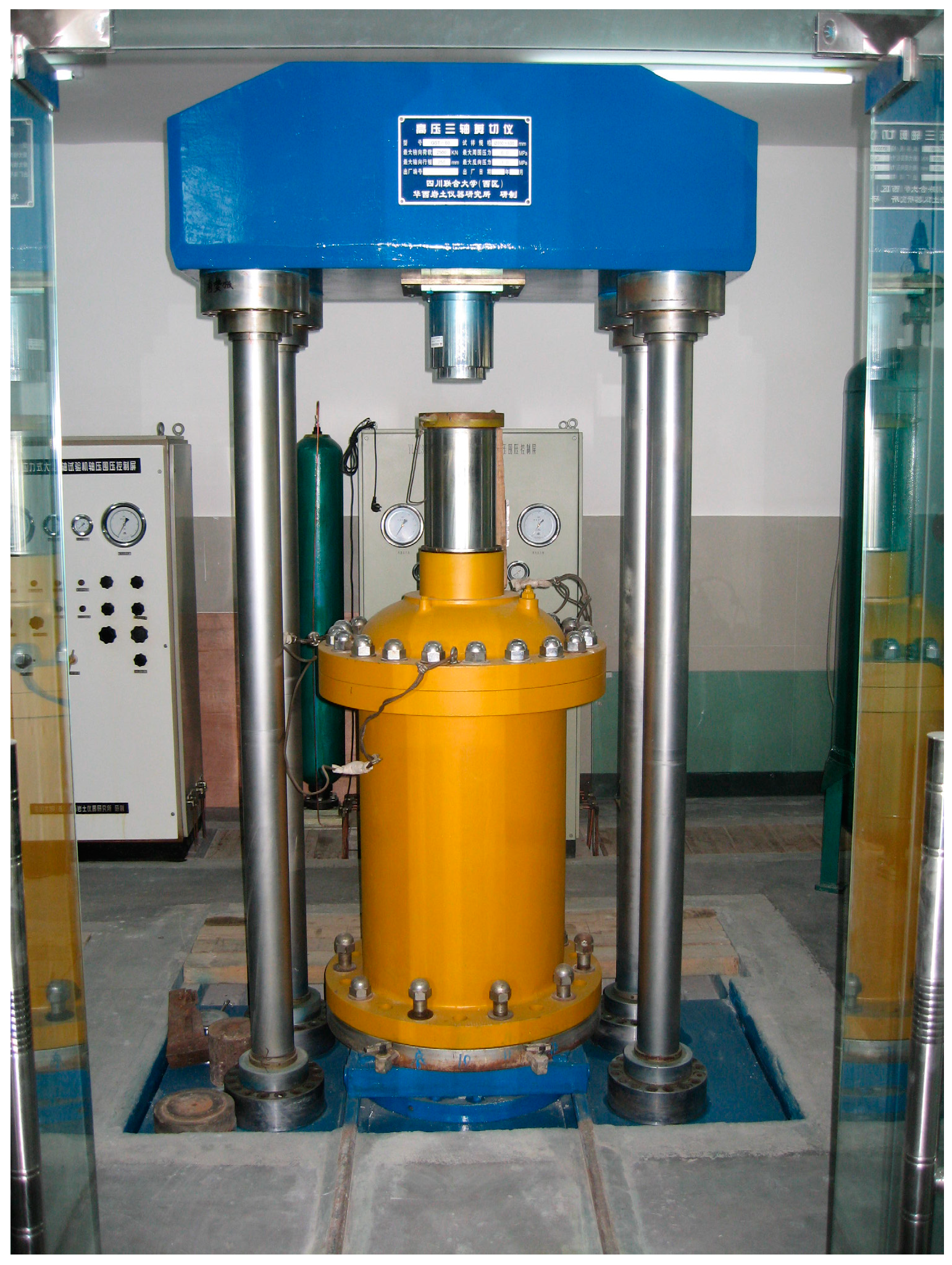
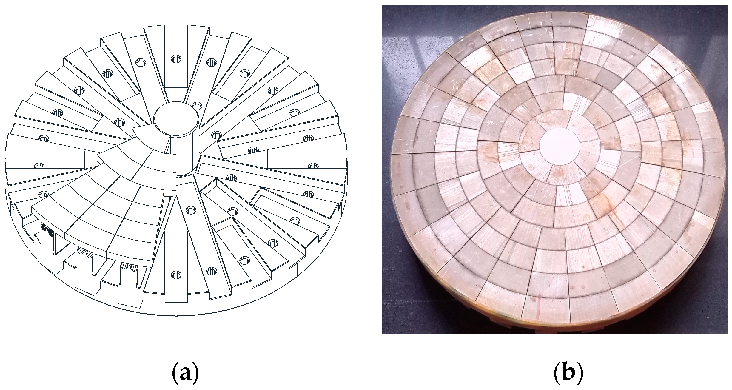
2.1. Test Equipment
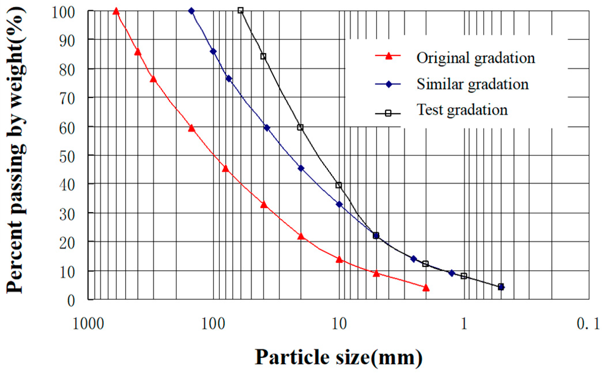
2.2. Test Materials
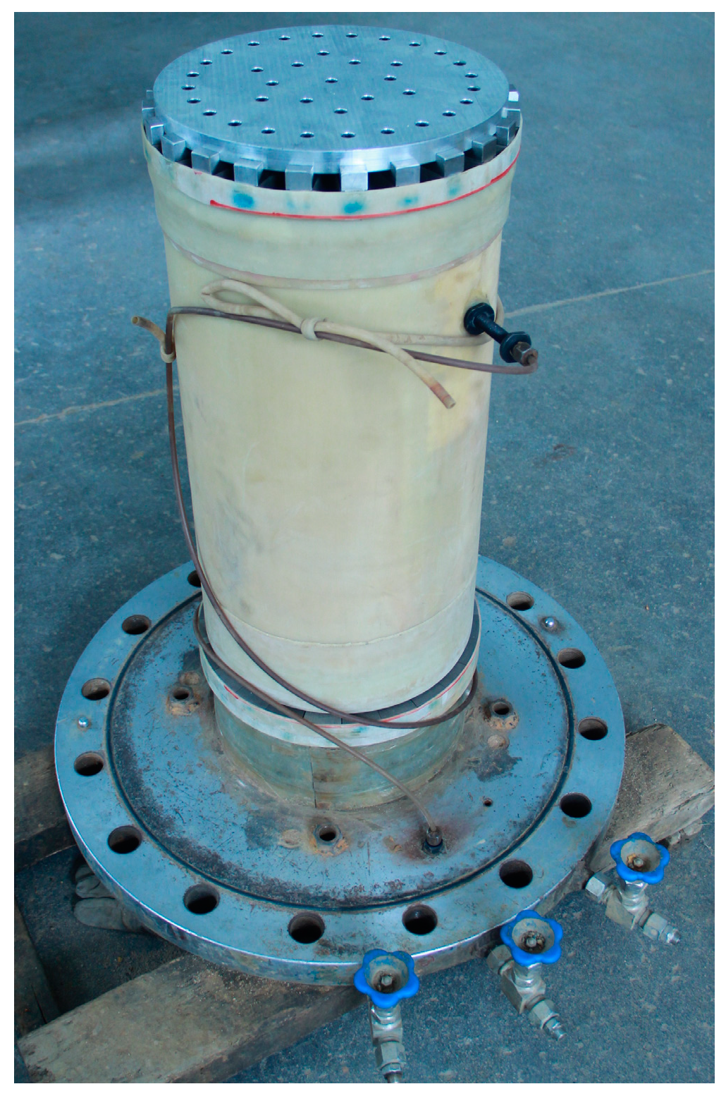
2.3. Triaxial Testing Procedure
3. Test Results and Discussion
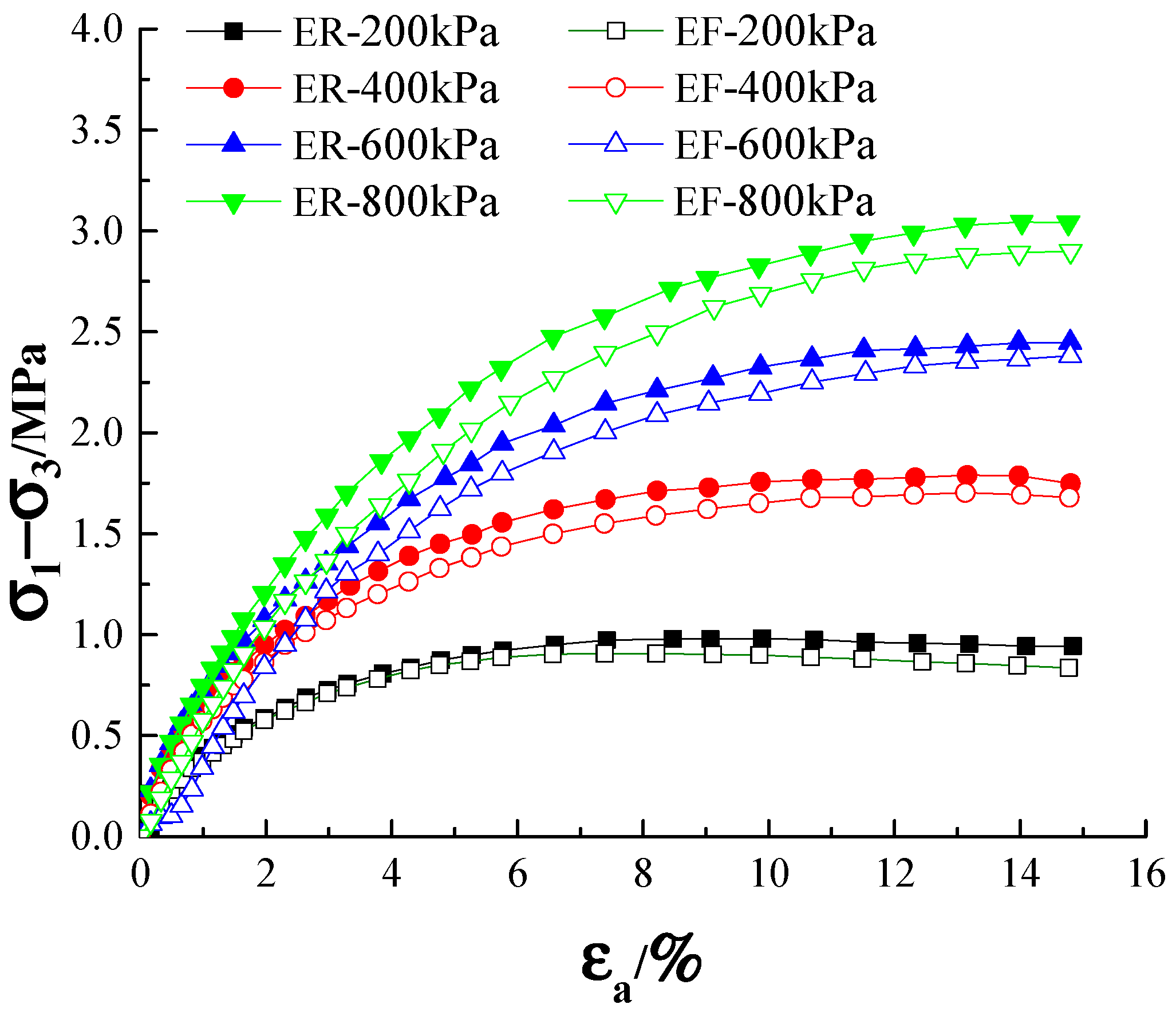
3.1. Stress–Strain Relationship
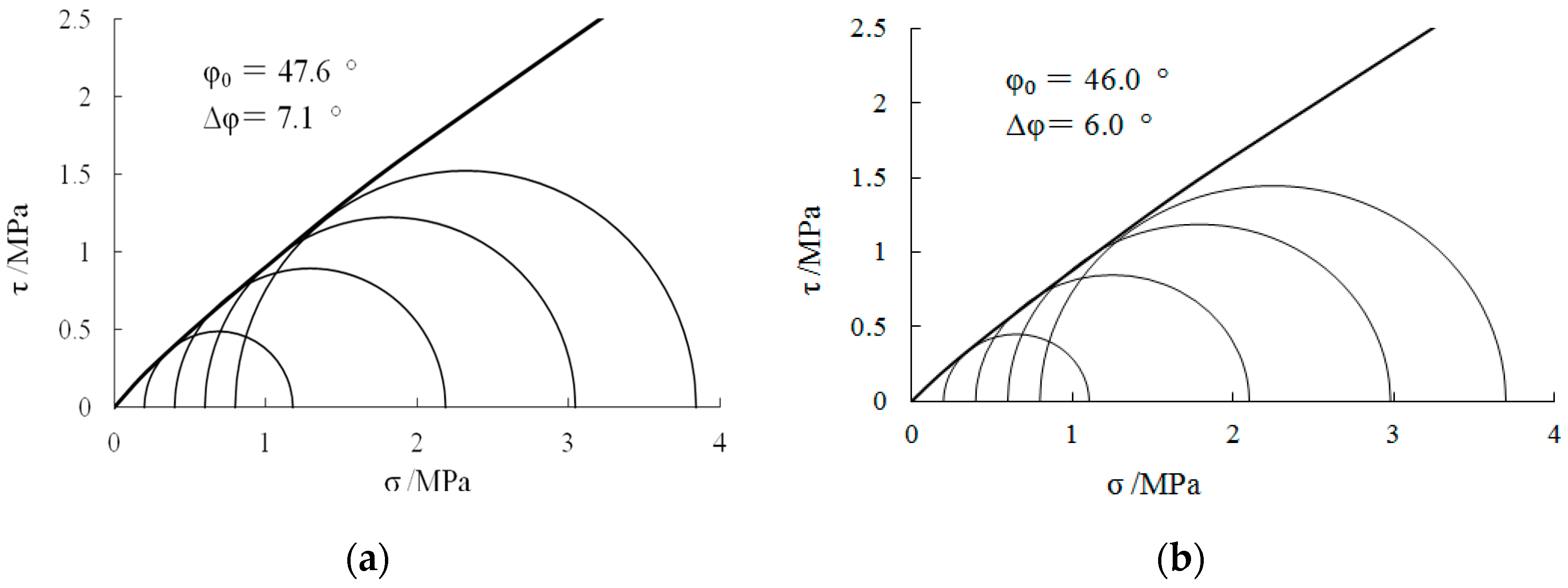
3.2. Strength Characteristics
3.3. Volumetric Strain Characteristics
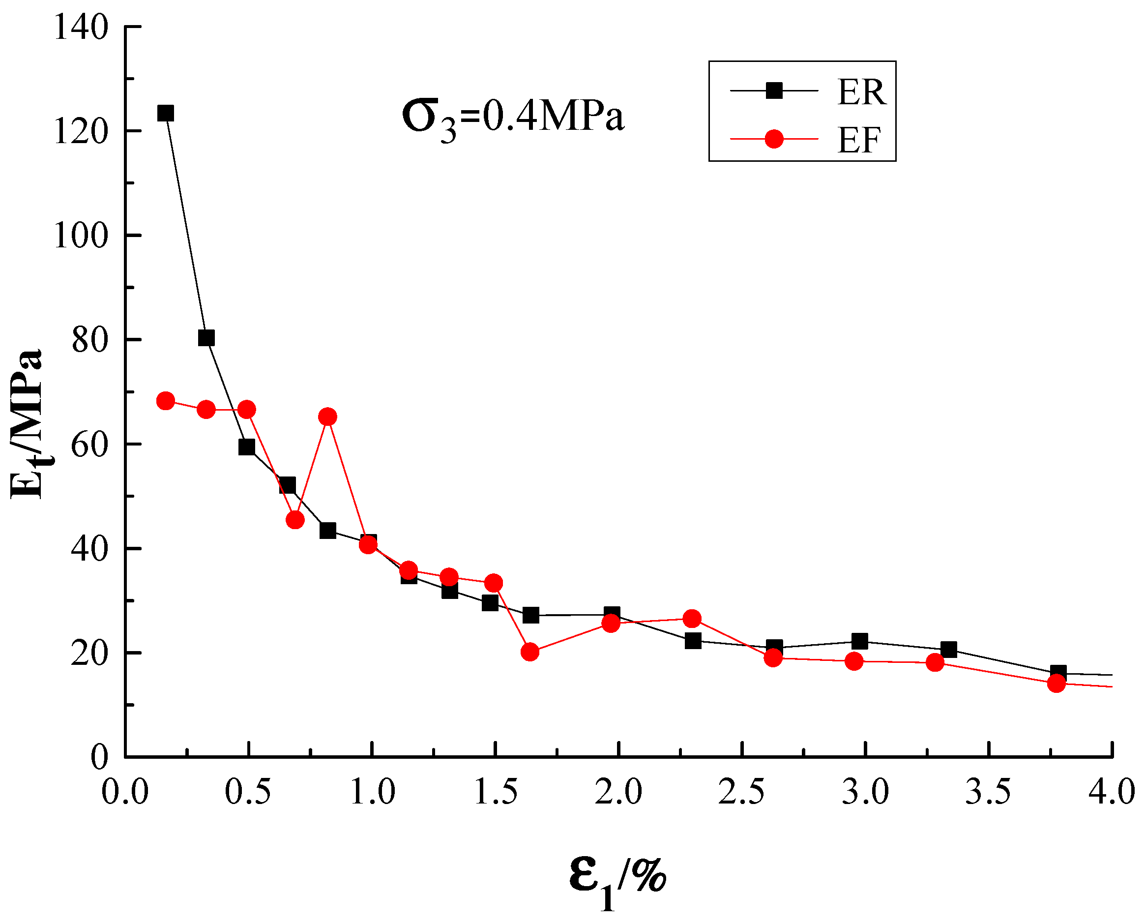
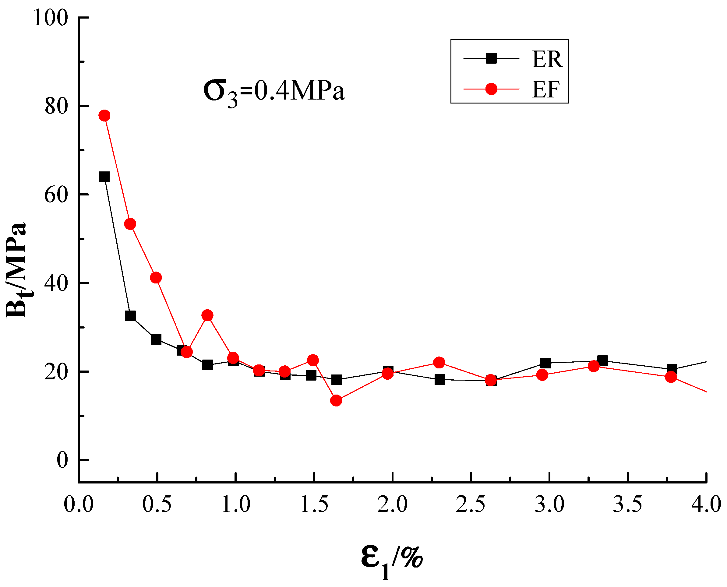
3.4. Modulus Characteristics
3.5. Duncan–Chang Model Parameters
3.6. Sample Deformation
4. Conclusions
- (1)
- The stress–strain relationship curves of the coarse-grained soil had similar properties under the end-restraint and end-free (microfriction) conditions. With regards to the dense coarse-grained soil, the deviator stress–strain curve of the specimen with the end restraint showed strain-softening behavior under a smaller confining pressure but strain-hardening behavior under a larger confining pressure. When it was subjected to a modest confining pressure, the behavior of the end-free specimen showed a more pronounced propensity to soften than the specimen with the end restraint.
- (2)
- The volumetric strain behavior of the coarse-grained soil was consistent both under the end-restraint and end-free (microfriction) conditions. Under a low confining pressure, the coarse-grained soil first exhibited volumetric contraction, followed by volumetric dilation, and only exhibited volumetric contraction under a higher confining pressure. The tendency of the coarse-grained soil to show volumetric shrinkage under a low confining pressure was more pronounced in the initial stages of shearing. With the emergence of shearing, the volumetric dilation tendency of the coarse-grained soil under the end-free (microfriction) condition became more pronounced. When the confining pressure was higher, the volumetric strain of the specimen with the end restraint was consistently greater than the end-free specimen, which displayed a marked tendency for volumetric contraction throughout the whole shearing process.
- (3)
- The end restraint had little effect on the strength parameters of the coarse-grained soil, but it had a greater impact on its deformation parameters. When the Duncan–Chang E-B and E-μ models were used for fitting, compared with the end-free (microfriction) model, the linear strength indices and and the nonlinear strength indices and of the end-restraint model were slightly increased. Further, the deformation parameter indicators and increased significantly, indicating that the end restraint condition had a higher effect than the end-free condition on the deformation properties of the coarse-grained soil.
- (4)
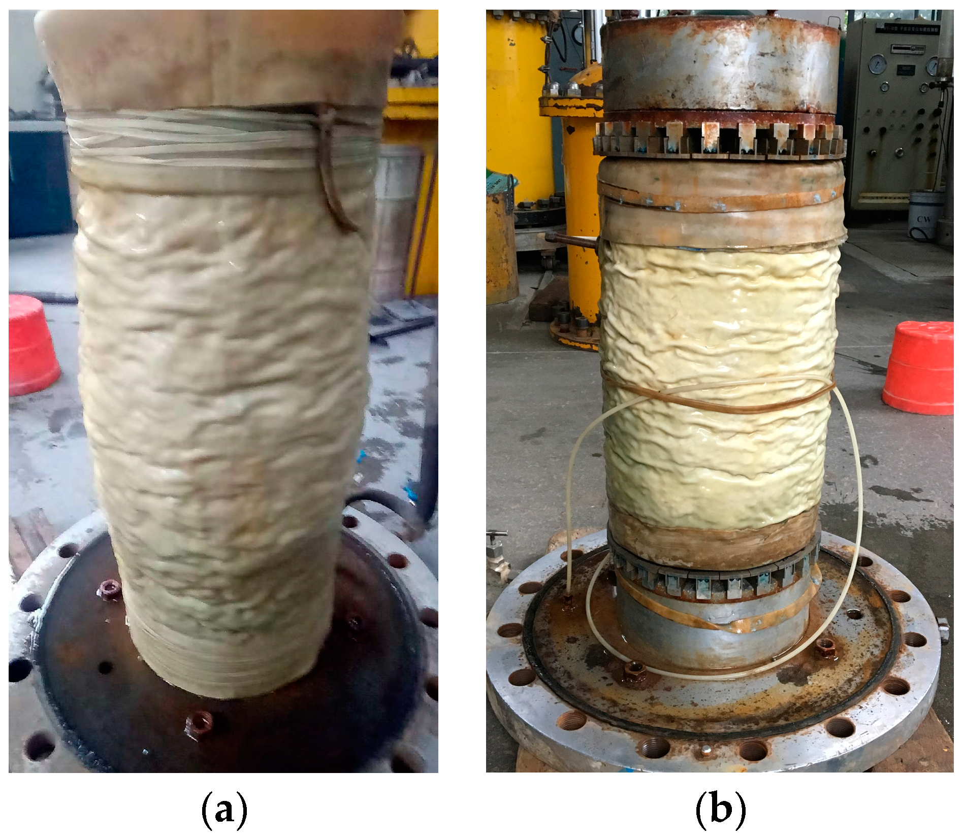
- For the end-restraint specimen, it can be seen that the end-restraint restricted the radial deformation at the specimen’s end, but the radial deformation of the specimen’s middle portion was significantly larger than that of the end-free specimen, indicating bulging. The microfriction-affected specimens had a substantially more consistent deformation distribution.
Author Contributions
Funding
Institutional Review Board Statement
Informed Consent Statement
Data Availability Statement
Acknowledgments
Conflicts of Interest
References
- Omar, T.; Sadrekarimi, A. Pecimen size effects on behavior of loose sand in triaxial compression tests. Can. Geotech. J. 2015, 52, 732–746. [Google Scholar] [CrossRef]
- Wei, X.X.; Chau, K.T. Finite and transversely isotropic elastic cylinders under compression with end constraint induced by friction. Int. J. Solids Struct. 2009, 46, 1953–1965. [Google Scholar] [CrossRef]
- Li, Y.L. Study on the Influence of End Contact and End Constraint in Geotechnical Triaxial Test. Master’s Thesis, Dalian University of Technology, Dalian, China, 2007. [Google Scholar]
- Duncan, J.M.; Dunlop, P. The significance of cap and base restraint. J. Soil Mech. Found. Div. 1968, 94, 271–290. [Google Scholar] [CrossRef]
- Timoshenko, S.P. History of Strength of Materials; Dover Publications Inc.: New York, NY, USA, 1983. [Google Scholar]
- Taylor, D.W. Seventh Progress Report on Shear Research to U.S. Engineers; MIT Publication: Cambridge, MA, USA, 1941. [Google Scholar]
- Rowe, P.W.; Barden, L. Importance of free ends in triaxial testing. J. Soil Mech. Found. Div. 1964, 90, 1–27. [Google Scholar] [CrossRef]
- Blight, G.E. Shear stress and pore pressures in triaxial testing. J. Soil Mech. Found. Div. 1965, 91, 25–39. [Google Scholar] [CrossRef]
- Bishop, A.W.; Green, E.G. The influence of end restraint on the compression strength of a cohesionless soil. Geotechnique 1965, 15, 243–266. [Google Scholar] [CrossRef]
- Lee, K.L. End restraint effects on undrained static triaxial strength of sand. J. Geotech. Eng. Div. 1978, 104, 687–704. [Google Scholar] [CrossRef]
- Ueng, T.; Tzou, Y.; Lee, C. The effect of end restraint on volume change and particle breakage of sands in triaxial tests. In Advanced Triaxial Testing of Soil and Rock; ASTM STP 977; ASTM International: West Conshohocken, PA, USA, 1988; pp. 679–691. [Google Scholar]
- Zhang, H.M.; Zeng, Q.L. Steady state strength of sand:concepts and experiment. Chin. J. Geotech. Eng. 1999, 21, 95–100. [Google Scholar]
- Lu, X.; Sun, M.; Chen, H.; Chu, F. Effects of end restraint in triaxial tests on coarse-grained soil. Chin. J. Geotech. Eng. 2010, 29, 1937–1944. [Google Scholar]
- Garga, V.K.; Zhang, H. Volume changes in undrained triaxial tests on sands. Can. Geotech. J. 1997, 34, 762–772. [Google Scholar] [CrossRef]
- Rechenmacher, A.L. Grain-scale processes governing shear band initiation and evolution in sands. J. Mech. Phys. Solids 2006, 54, 22–45. [Google Scholar] [CrossRef]
- Han, L.; Penumadu, D. Strain localization in combined axial-torsional testing on kaolin clay. J. Eng. Mech. 2006, 132, 555–564. [Google Scholar]
- Jacquot, P.; Facchini, M. Interferometric imaging: Involvement in civil engineering. J. Comput. Civ. Eng. 1999, 13, 59–60. [Google Scholar] [CrossRef]
- Shao, L.T.; Wang, Z.P.; Liu, Y.L. Digital image processing technique for measurement of the local deformation of soil specimen in triaxial tests. Chin. J. Geotech. Eng. 2002, 24, 159–163. [Google Scholar]
- Shao, L.T.; Sun, Y.Z.; Wang, Z.P.; Liu, Y.L. Application of digital image processing technique to triaxial test in soil mechanics. Rock Soil Mech. 2006, 27, 29–34. [Google Scholar]
- Wang, Z.P.; Shao, L.T. Research on influence of end effect of soil specimens in triaxial tests. Rock Soil Mech. 2003, 24, 363–368. [Google Scholar]
- Dong, J.J.; Shao, L.T. Study of unsaturated compacted soil considering influence of end effect by triaxial test. Chin. J. Rock Mech. Eng. 2010, 29, 1937–1944. [Google Scholar]
- Airey, D.W. Finite element analyses of triaxial tests with different end and drainage conditions. In Proceedings of the 7th International Conference on Computer Methods and Advances in Geomechanics, Cairns, Australia, 6–10 May 1991; Volume 1, pp. 225–230. [Google Scholar]
- Schanz, T.; Gussmann, P. The influence of geometry and end restraint on the strength in triaxial compression in numerical simulation. In Proceedings of the 3rd European Conference in Numerical Methods in Geotechnical Engineering, Manchester, UK, 7–9 September 1994; Balkema: Rotterdam, The Netherlands, 1994; pp. 129–133. [Google Scholar]
- Sheng, D.; Westerberg, B.; Mattsson, H.; Axelsson, K. Effects of end restraint and strain rate in triaxial tests. Comput. Geotech. 1997, 21, 163–182. [Google Scholar] [CrossRef]
- Jeremic, B.; Yang, Z.H.; Sture, S. Numerical assessment of the influence of end conditions on constitutive behavior of geomaterials. J. Eng. Mech. 2004, 130, 741–745. [Google Scholar] [CrossRef]
- Liyanapathirana, D.S.; Carter, J.P.; Airey, D.W. Numercal modeling of nonhomogencous behavior of structured soils during triaxial tests. Int. J. Geomcchanics 2005, 5, 10–23. [Google Scholar] [CrossRef]
- Hashash, Y.M.; Fu, Q.; Ghaboussi, J.; Lade, P.V.; Saucier, C. Inverse analysis-based interpretation of sand behavior from triaxial compression tests subjected to full end restraint. Can. Geotech. J. 2009, 46, 768–791. [Google Scholar] [CrossRef]
- Cheng, Z.; Wang, Y.; Pan, J.; Xu, H.; Wang, J. A Micro-Friction Load Transfer Plate in Triaxial Compression Test of Geotechnical Engineering. Chinese Patent CN201410333749, 14 July 2014. (In Chinese). [Google Scholar]
- Duncan, J.M.; Chang, C.Y. Nonlinear analysis of stress and strain in soils. J. Soil Mech. Found. Eng. Div. 1970, 96, 1629–1653. [Google Scholar] [CrossRef]
- Duncan, J.M.; Byrne, P.; Wong, K.S.; Mabry, P. Strength, Stress-Strain and Bulk Modulus Parameters for Finite Element Analyses of Stresses and Movements in Soil Massses; Report No. UBC/GT/80-01; Department of Civil Engineering, University of California: Berkeley, CA, USA, 1980. [Google Scholar]


| Minimum Dry Density, ρdmin (g/cm3) | Maximum Dry Density, ρdmax (g/cm3) | Specific Gravity Gs | Test Dry Density, ρd (g/cm3) | Porosity N (%) | Relative Density Dr |
|---|---|---|---|---|---|
| 1.629 | 2.178 | 2.72 | 2.11 | 22.4 | 0.90 |
| Confining Pressure (MPa) | Peak Strength (MPa) | Error | ||
|---|---|---|---|---|
| End Restraint | End Free (Microfriction) | Peak Strength Increasing Ratio (%) | ||
| 0.2 | 0.981 | 0.907 | 7.5 | - |
| 0.4 | 1.789 | 1.703 | 4.8 | - |
| 0.6 | 2.447 | 2.382 | 2.7 | - |
| 0.8 | 3.045 | 2.910 | 4.4 | - |
| Test Program | Shear Strength Index | E~B(μ) Model Parameters | ||||||||||
|---|---|---|---|---|---|---|---|---|---|---|---|---|
(kPa) | (°) | (°) | (°) | |||||||||
| End restraint | 82.5 | 39.2 | 47.6 | 7.1 | 614 | 0.23 | 0.83 | 279 | 0.12 | 0.379 | 0.337 | 5.50 |
| End free (microfriction) | 77.1 | 38.8 | 46.0 | 6.0 | 521 | 0.21 | 0.77 | 218 | 0.10 | 0.383 | 0.113 | 1.91 |
Disclaimer/Publisher’s Note: The statements, opinions and data contained in all publications are solely those of the individual author(s) and contributor(s) and not of MDPI and/or the editor(s). MDPI and/or the editor(s) disclaim responsibility for any injury to people or property resulting from any ideas, methods, instructions or products referred to in the content. |
© 2023 by the authors. Licensee MDPI, Basel, Switzerland. This article is an open access article distributed under the terms and conditions of the Creative Commons Attribution (CC BY) license (https://creativecommons.org/licenses/by/4.0/).
Share and Cite
Wang, Y.; Pan, J.; Zhang, H.; Zhou, S.; Xu, H. Study on the Strength and Deformation Characteristics of Coarse-Grained Soil under End-Restraint and End-Free (Microfriction) Conditions. Appl. Sci. 2023, 13, 11521. https://doi.org/10.3390/app132011521
Wang Y, Pan J, Zhang H, Zhou S, Xu H. Study on the Strength and Deformation Characteristics of Coarse-Grained Soil under End-Restraint and End-Free (Microfriction) Conditions. Applied Sciences. 2023; 13(20):11521. https://doi.org/10.3390/app132011521
Chicago/Turabian StyleWang, Yanli, Jiajun Pan, Hailong Zhang, Song Zhou, and Han Xu. 2023. "Study on the Strength and Deformation Characteristics of Coarse-Grained Soil under End-Restraint and End-Free (Microfriction) Conditions" Applied Sciences 13, no. 20: 11521. https://doi.org/10.3390/app132011521
APA StyleWang, Y., Pan, J., Zhang, H., Zhou, S., & Xu, H. (2023). Study on the Strength and Deformation Characteristics of Coarse-Grained Soil under End-Restraint and End-Free (Microfriction) Conditions. Applied Sciences, 13(20), 11521. https://doi.org/10.3390/app132011521