
Verifying the Stability of the Working Fronts of Lignite Open Pits Developed in Hilly Areas—A Case Study of Jilț North Open Pit (Romania)


Abstract
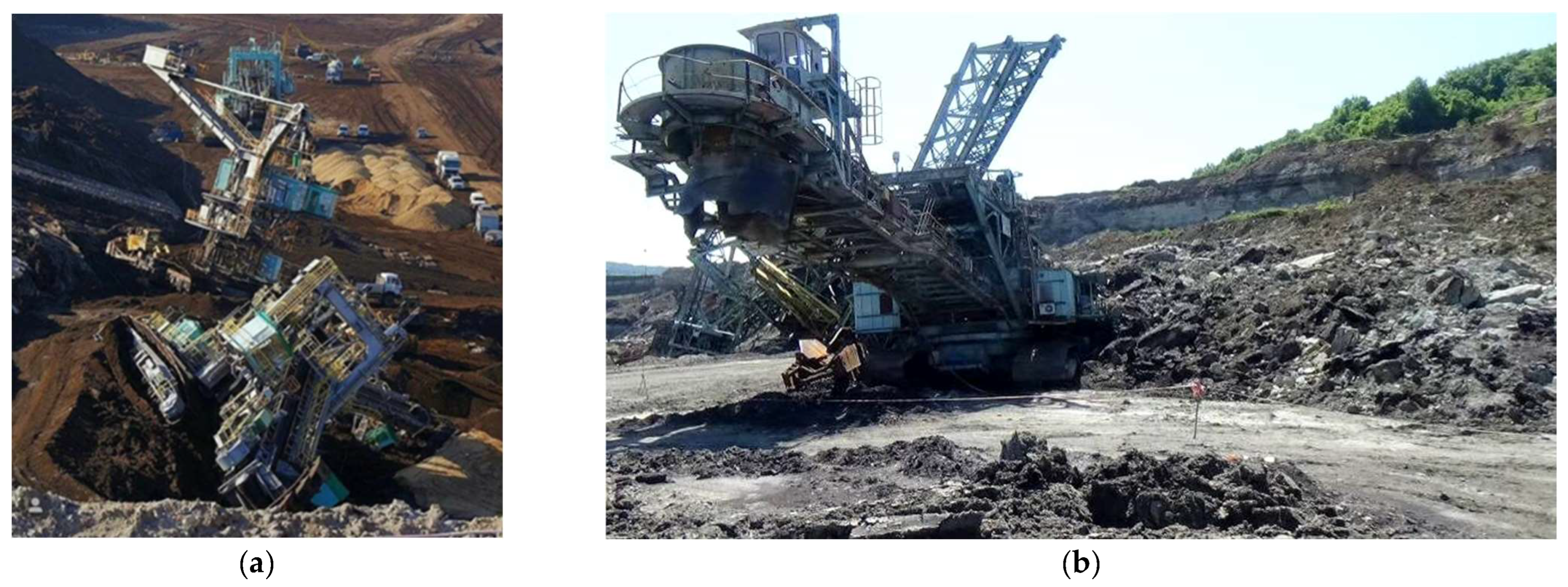
:1. Introduction
2. Description of Jilț North Mining Perimeter
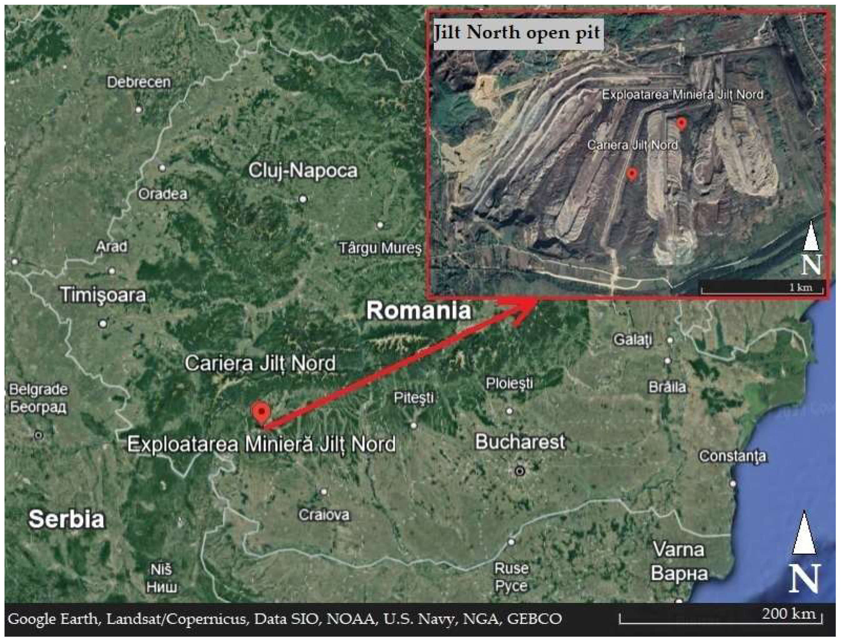
2.1. Location and Short Geological Description
- Filiaşi–Turceni–Dragoteşti–Mătăsari railway;
- County road DJ 673 Turceni–Dragotești–Strâmba–Vulcan, connected to DN 66 Craiova–Târgu Jiu, which ensures access from the south;
- The modernized county road Pieptani–Strâmba–Mătăsari, connected to DN 67 Târgu Jiu–Motru–Drobeta-Turnu Severin, which provides access from the north and west.
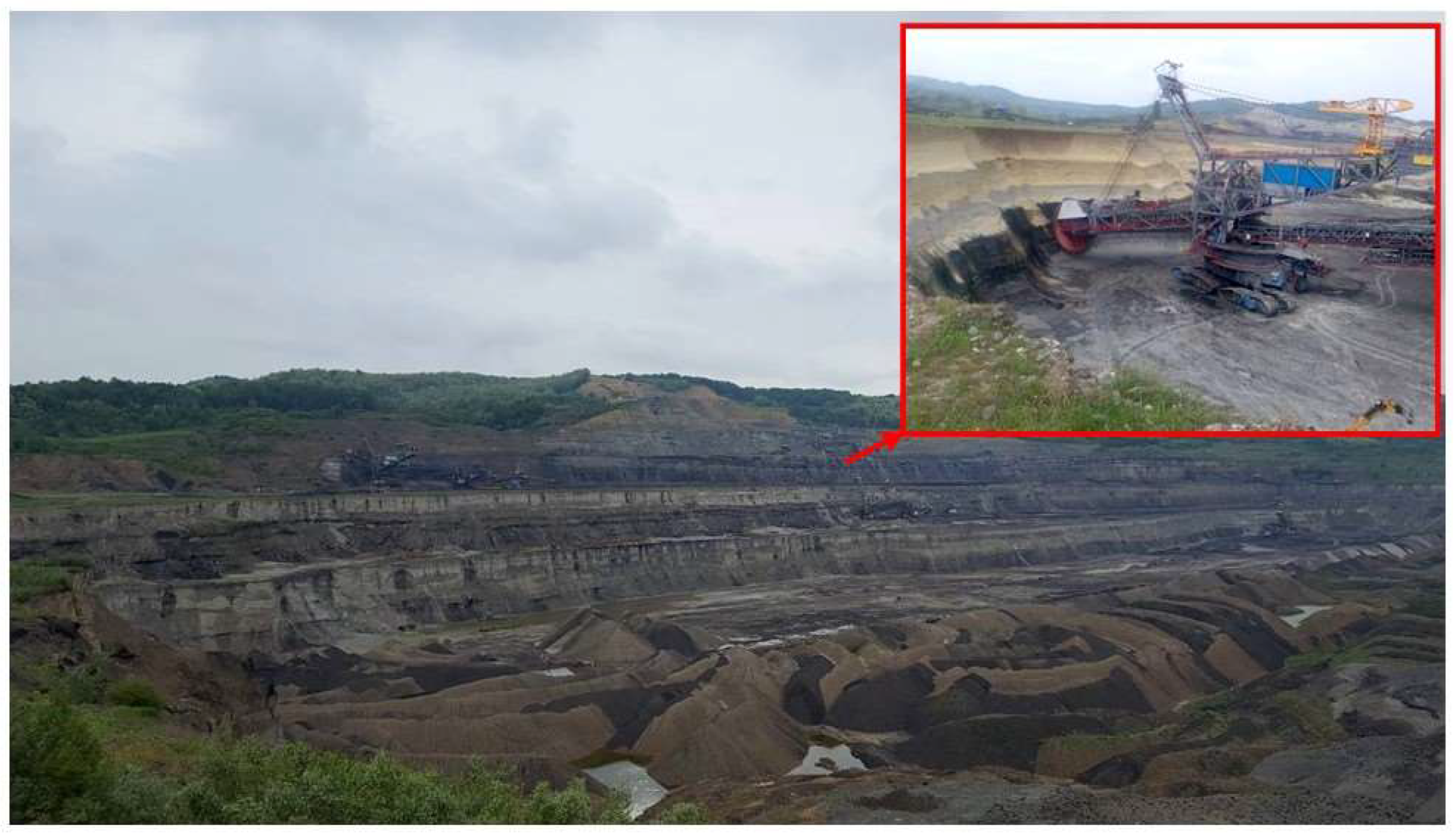
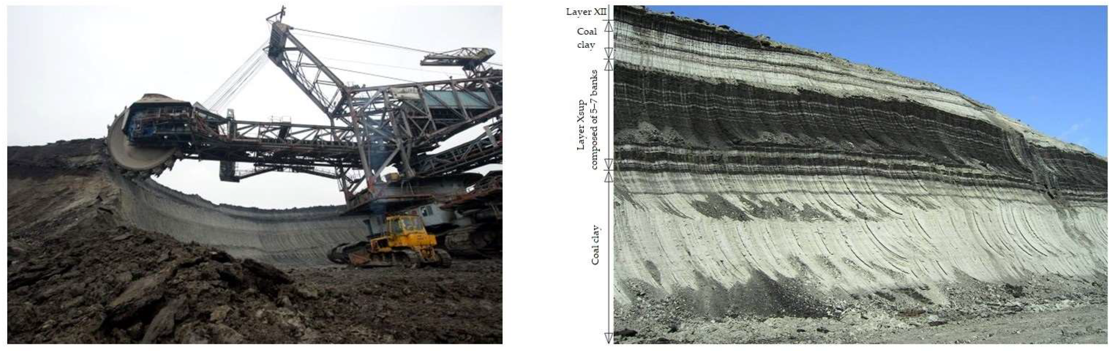
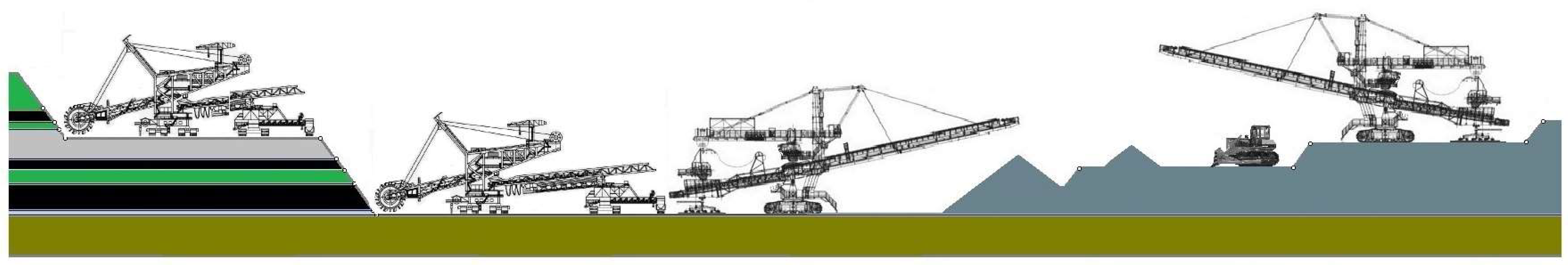
2.2. Equipment and Working Technologies
- BWEs: 6 × SRs 1400—30/7 (E06; E07; E14; E17; E18; E19);
- BWEs: 3 × SRs 470—15/3.5 (E09; E11; E16)—removed from the technological flux (in conservation, near the premises of the administrative building and the coal depot);
- High capacity conveyor belts, types: B1400; B1600; B1800; B2000; B2250, over 30 km;
- Belt wagons;
- Spreaders: 3 × A2RsB 6500.90 (A01, A03, A05) and one A2RsB 6500.60 (A02);
- Depositing machines: combined machine-type KsS 5600 × 40 and stacking machine-type ASG 6000.
3. Stability Analyses for the Initially Designed Geometry
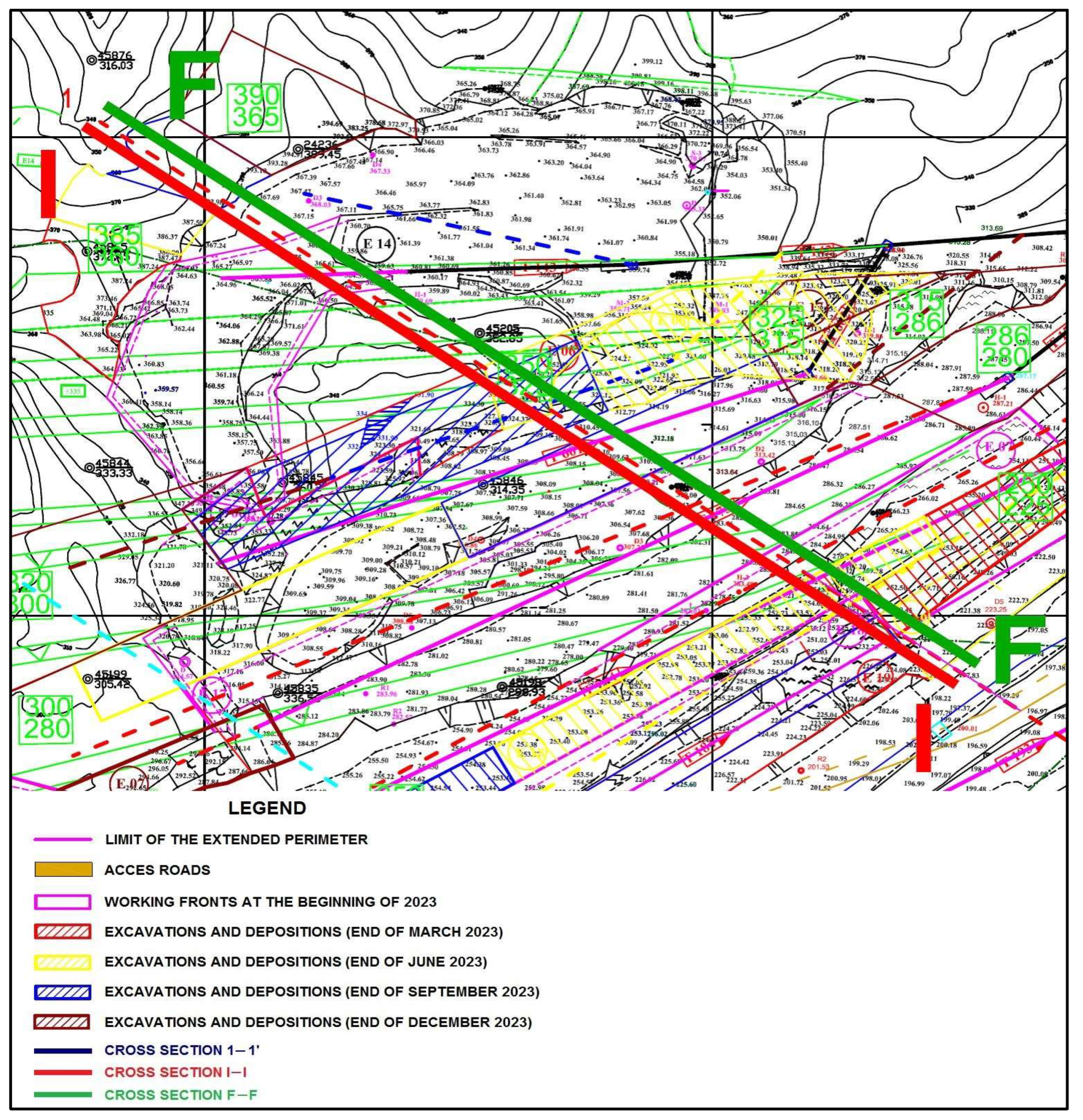
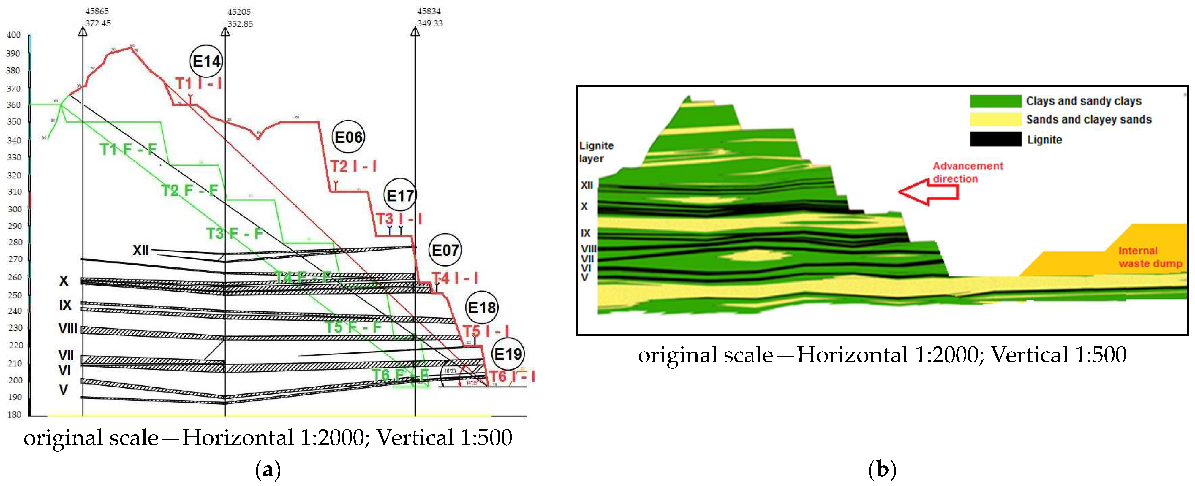
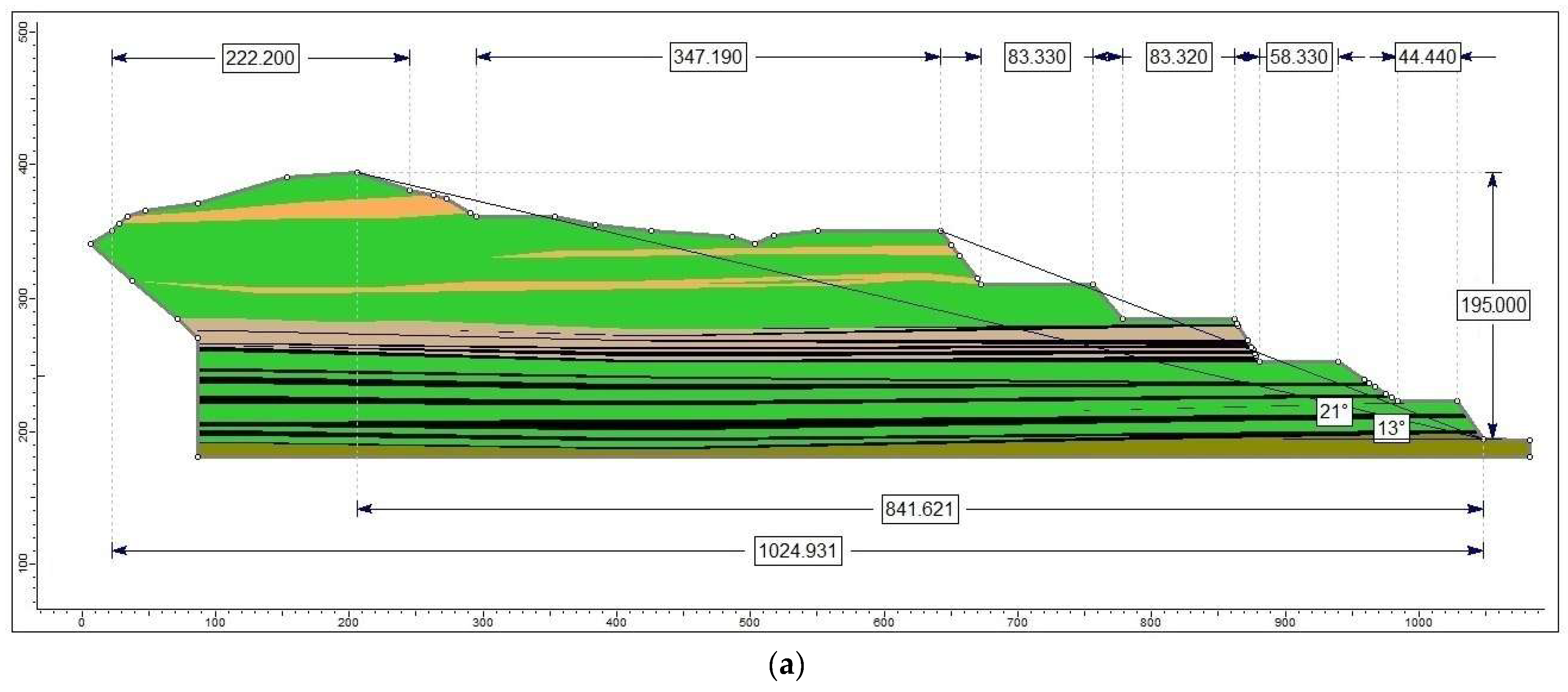
3.1. Modeling the Analysis Section
3.2. Preliminary Studies and Investigations
- 1.
- Studying the documentation made available by Jilț North open pit (description of the lignite deposit, the results of several geotechnical drillings, situation plan, longitudinal and cross sections, stratigraphic columns, etc.) [43], as well as previous research/service contracts, which concerned this exploitation perimeter;
- 2.
- On site investigations related to the technical condition of the slopes of the working fronts. During these field visits, discussions took place with representatives of the Jilț North open pit, regarding working technologies and problems of slope stability encountered so far. From these discussions, it was established that, in essence, the slopes exhibit some degree of instability. There are flows of material on the slopes in both dry and wet conditions. Following these field visits, some relevant findings were made:
- There are some geometric non-uniformities of the working fronts caused by the morphology of the terrain and excavation technology;
- Rock displacements (dry flows and material rolling) in conditions of low humidity and tendencies of plastic flow in conditions of saturation especially on the slopes of T1, T2 and T3 steps. Usually they do not involve large volumes of material (can be regarded as superficial landslides);
- Displacements that affect the stability of the step over the entire height, with variable extent depending on the slope structure and the hydrometeorological conditions.
- 3.
- Determining some physical and mechanical characteristics relevant for the rocks encountered in the slopes of the working fronts through laboratory tests, retrieving data from the specialized literature and their statistical processing.
3.3. Selection of Physical–Mechanical Characteristics
- S1 clays from step T1;
- S2 clayey sands from step T1;
- S3 clays from step T2;
- S4 clayey sands from step T2;
- S5 clays from step T3;
- S6 coal clay from step T4;
- S7 lignite from step T4 (layer X);
- S8 lignite from step T5 (layer VIII);
- S9 clays from step T5;
- S10 clays from step T6.
3.4. Results of the Stability Analyses
- The static equilibrium of each strip is ensured by the equilibrium of the projections in two orthogonal directions and the equilibrium of the moments of the forces with respect to any point;
- Total vertical equilibrium is ensured when the vertical component of the resistance forces on the sliding surface balances the entire weight of the body (including external forces) and the vertical forces on the contour;
- Total horizontal equilibrium is ensured when the horizontal component of the resistance forces acting on the sliding surface is in equilibrium with the horizontal forces acting on the contour;
- The equilibrium of the total moments is ensured when the sum of the moments of the differential forces between the slices is in equilibrium with the moments of the forces acting on the contour.
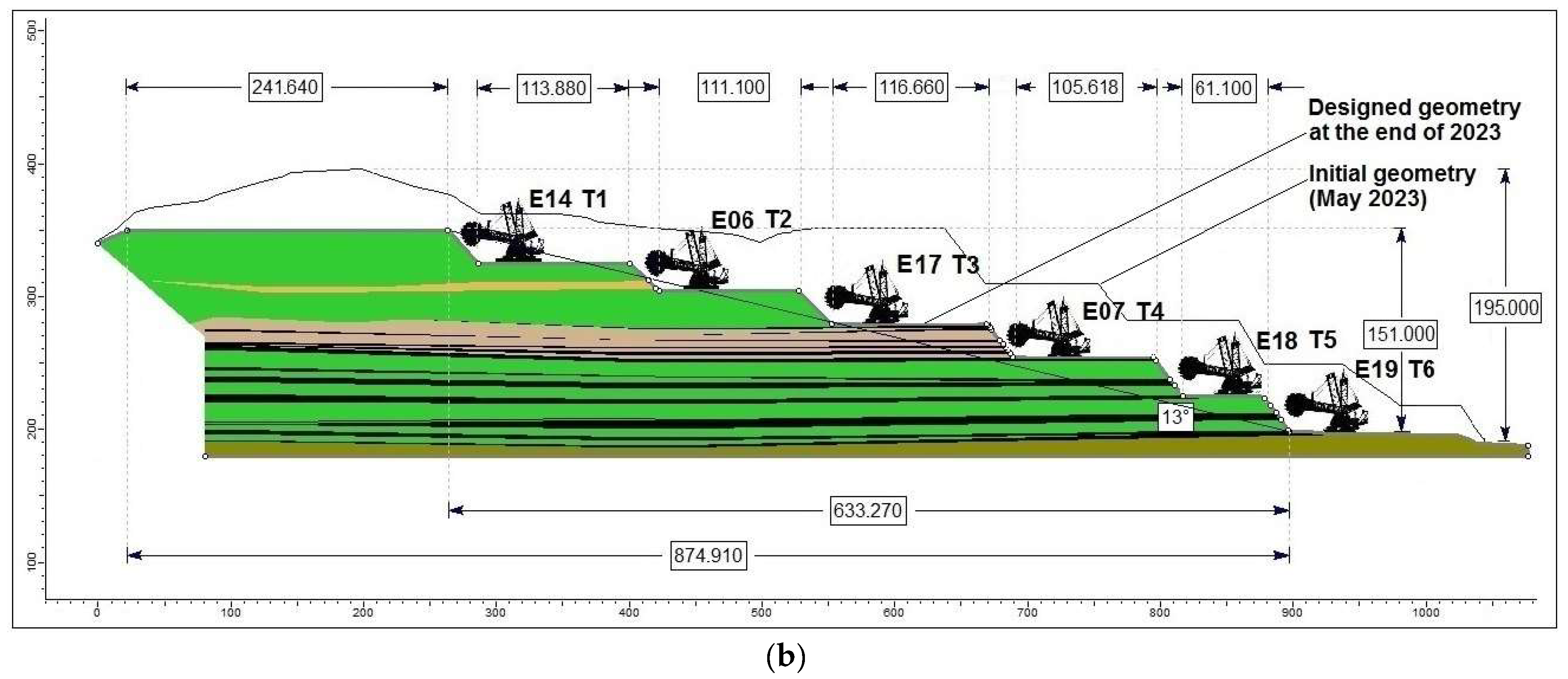
- The stability analyses in this paragraph were carried out for the designed conditions, the geometry considered for the analysis section to be achieved at the end of 2023, and took into account the stratigraphic columns received from the Jilț North open pit;
- For most situations, the lowest values of the stability factor were determined by Janbu’s method;
- For the T1 step, the stability analyses highlighted a sub-unit value of the stability factor, i.e., a slope below the equilibrium limit. The main reasons are represented by the relatively unfavorable geometrical elements (height of 25 m and inclination of 48°), but also by the physical–mechanical characteristics of the rocks in the structure of the slope. In order to solve the problem of the stability of this step, a reshaping of the initially designed geometric elements is necessary, by using a scientific method, which guarantees the continuation of extractive activities in safe conditions;
- In the case of the T3 step, following the performance of stability analyses, it was found that there is the possibility of materializing a critical sliding surface, which starts from approx. 5 m away from the edge of the upper berm and passes close to the tip of the slope. Such a slide, although superficial, can cause interruptions in the productive activity and, implicitly, economic losses. To prevent such a situation, a reshaping of the geometric elements is also recommended;
- For the rest of the situations analyzed (the rest of the individual slopes, different systems of steps, and the general slope), the values of the stability factor indicate a satisfactory reserve, in accordance with the national technical prescriptions [67] and the recommendations from the specialized literature [2,3,4,5,7,8,9,10,17,49,57] (in general, they recommend a minimum stability reserve between 10 and 15% for working slopes—with a reduced duration of staying in place);
- In the case of the steps whose structure also includes lignite layers (T4–T6), although they have more unfavorable geometrical elements (theoretically) than the steps excavated in waste rocks (T1–T3), due to the superior physical and mechanical characteristics of lignite (especially the shear strength), the values of the stability factor (coefficient) are satisfactory (stability reserves above 15%).
4. Redesigning the Unstable Working Fronts
- Construction of a sub-step ST1, with a height of 10 m, a berm of 25–30 m, and a slope angle of 45°, excavated using a BWE type SRs 470, and a second sub-step ST2, 15 m high, excavated using BWE E14, type SRs 1400—30 (currently operating on the T1 step). At the same time, the slope angle for the ST2 sub-step will be reduced to 40°. Since the three BWEs type SRs 470 excavators, under conservation (as specified in paragraph 2.2), are at a distance of approx. 4 km and at a difference in elevation of more than 150 m compared to the elevation of the T1 excavation step, this option would involve a relatively long period of interruption in the productive flux, with important economic consequences, which is why it is not recommended.
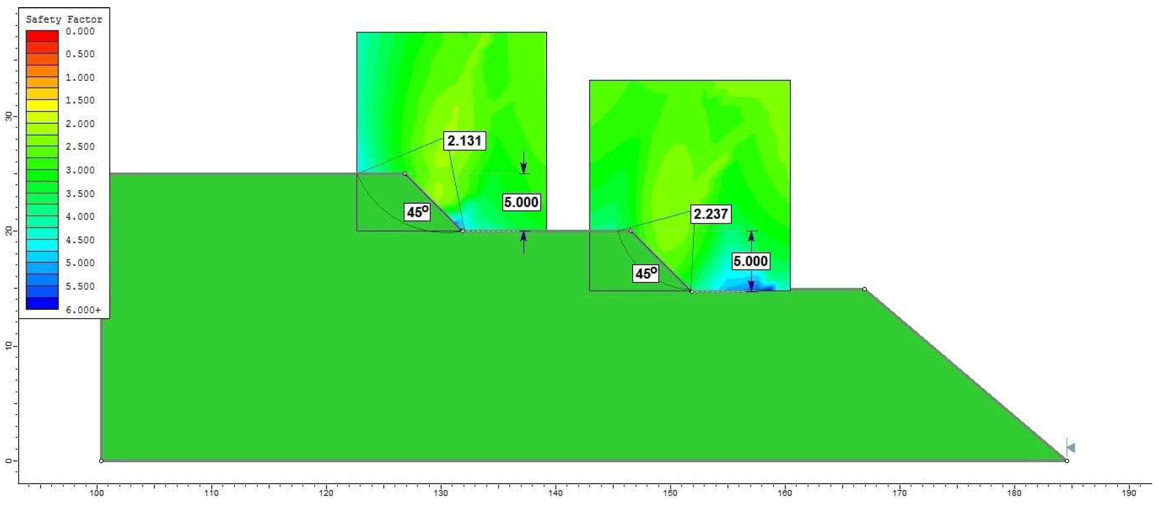
- Construction of two sub-steps, ST1 and ST2, with a height of 5 m, berms of 15 m, and a slope angle of 45°, excavated with wheeled classic excavators and transport of waste rocks with dumping trucks (discontinuous flux) and a third sub-step ST3, 15 m high, excavated with BWE E14, type SRs 1400—30 (currently operating on the T1 step). At the same time, the slope angle for the ST3 sub-step will be reduced to 40° (Figure 17).
5. Discussion and Conclusions
Author Contributions
Funding
Institutional Review Board Statement
Informed Consent Statement
Data Availability Statement
Conflicts of Interest
References
- Lazar, M.; Faur, F.; Apostu, I.M. Stability conditions in lignite open pits from Romania. Case study: Oltețu open pit. Appl. Sci. 2022, 12, 9607. [Google Scholar] [CrossRef]
- Hoek, E.; Bray, J.W. Rock Slope Engineering, 3rd ed.; Institution of Mining and Metallurgy: London, UK, 1981. [Google Scholar]
- Duncan, C.W.; Christopher, W.M. Rock Slope Engineering. Civil and Mining, 4th ed.; Spon Press—Taylor & Francis Group: New York, NY, USA, 2004; Available online: https://civilenglineering.files.wordpress.com/2014/10/rock_slope_engineering_civil_and_mining.pdf (accessed on 4 July 2023).
- Duncan, J.M.; Wright, S.G.; Brandon, T.L. Soil Strength and Soil Stability, 2nd ed.; JohnWiley & Sons, Inc.: Hoboken, NJ, USA, 2014; pp. 81–132. [Google Scholar]
- Derek, H.C. Landslides in Practice: Investigation, Analysis, and Remedial/Preventative Options in Soils; John Wiley & Sons, Inc.: Hoboken, NJ, USA, 2005; pp. 170–219. [Google Scholar]
- Soltanmohammadi, M.; Osanloo, A.S.; Malekzadeh, S.B. Selection of practical bench height in open pit mining using a multicriteria decision-making solution. J. Geol. Min. Res. 2010, 2, 48–59. [Google Scholar] [CrossRef]
- Stanciucu, M. Stability of Natural and Artificial Slopes; Technical: Bucharest, Romania, 2018; pp. 11–150. (In Romanian) [Google Scholar]
- Abramson, L.W.; Lee, T.S.; Sharma, S.; Boyce, G.M. Slope Stability and Stabilization Methods; JohnWiley & Sons, Inc.: New York, NY, USA, 2002; pp. 378–382. [Google Scholar]
- Huang, Y.H. Slope Stability Analysis by the Limit Equilibrium Methods: Fundamentals and Methods; ASCE Press: New York, NY, USA, 2014; pp. 229–264. [Google Scholar]
- Salgado, R. The Engineering of Foundation Slopes and Retaining Structures, 2nd ed.; CRC Press: Boca Raton, FL, USA, 2022; pp. 894–917. [Google Scholar]
- Dana, H.; Kakaie, R.; Rafiee, R.; Bafghi, A. Effects of geometrical and geomechanical properties on slope stability of open-pit mines using 2D and 3D finite difference methods. J. Min. Environ. 2018, 9, 941–957. [Google Scholar] [CrossRef]
- Luo, S.; Huang, D.; Peng, J.; Tomás, R. Influence of permeability on the stability of dual-structure landslide with different deposit bedding interface morphology: The case of the three Gorges Reservoir area. China Eng. Geol. 2022, 296, 106480. [Google Scholar] [CrossRef]
- Kumar, M.; Raj Kumar, M. Factors Affecting Slope Stability of an Opencast Mine: A Brief Study. Int. J. Innov. Sci. Res. Technol. 2022, 7, 878–882. [Google Scholar] [CrossRef]
- Wang, C.Y.; Zhang, F.; Han, W.D. Sensitivity Analysis of Slope Stability Influence Factors Based on BP Neural Network. Adv. Mat. Res. 2014, 1010, 1544–1547. [Google Scholar] [CrossRef]
- Młyńczak, M. Bucket wheel excavators: Past to present experiences in safety operation. In Proceedings of the PSAM 12 (Probabilistic Safety Assessment and Management), Honolulu, HI, USA, 26 June 2014; Available online: https://silo.tips/download/bucket-wheel-excavators-past-to-present-experiences-in-safety-operation (accessed on 25 July 2023).
- Bošnjak, S.M.; Savićević, S.D.; Gnjatović, N.; Milenović, I.L.J.; Pantelić, M.P. Disaster of the bucket wheel excavator caused by extreme environmental impact: Consequences, rescue and reconstruction. Eng. Fail. Anal. 2015, 56, 360–374. [Google Scholar] [CrossRef]
- Faur, F.; Lazăr, M.; Apostu, I.M. Land Stability in the Influence Areas of Lignite Open Pits. A Case Study for the Berbești Mining Basin (Romania); Lambert Academic Publisher: Saarbrucken, Germany, 2022; p. 108. Available online: https://www.lap–publishing.com/catalog/details/store/gb/book/978-620-5-52831-0/land-stability-in-the-influence-areas-of-lignite-open-pits?search=Faur (accessed on 2 August 2023)ISBN 978-620-5-52831-0.
- Available online: https://www.reddit.com/r/CatastrophicFailure/comments/ojt6tu/bucket_wheel_excavator_collapse_51195/?rdt=34247 (accessed on 1 August 2023).
- Steiakakis, E.; Kavouridis, K.; Monopolis, D. Large scale failure of the external waste dump at the “South Field” lignite mine, Northern Greece. Eng. Geol. 2009, 104, 269–279. [Google Scholar] [CrossRef]
- Ylber, M. Evaluation of landslides and engineering measures on lignite open pit slope in south east Sibovc-Kosovo Coal Basin. In Proceedings of the Landslide and Flood Hazard Assessment, 1st Regional Symposium on Landslides in the Adriatic-Balkan Region and 3rd Workshop of the Japanese-Croatian Project “Risk Identification and Land-Use Planning for Disaster Mitigation of Landslides and Floods in Croatia”, Zagreb, Croatia, 6–9 March 2013; Arbanas, S.M., Arbanas, Z., Eds.; City of Zagreb Emergency Management Office: Zagreb, Croatia, 2013; Volume 1. [Google Scholar]
- Bednarczyk, Z. Slope instabilities in Polish open-pit mines. In Landslides and Engineered Slopes. Experience, Theory and Practice, 1st ed.; CRC Press: New York, NY, USA; Taylor and Francis Group: New York, NY, USA, 2016; 9p. [Google Scholar] [CrossRef]
- Steiakakis, C.; Apostolou, E.; Papavgeri, G.; Agioutantis, Z.G.; Schilizzi, P. Large moving landslide inside a lignite mine in northern Greece. In Landslides and Engineered Slopes. Experience, Theory and Practice; CRC Press: New York, NY, USA; Taylor and Francis Group: New York, NY, USA, 2016. [Google Scholar] [CrossRef]
- Steiakakis, E.; Thalassinakis, J.; Agioutantis, Z.G.; Galetakis, M. Failure process of the external waste dump of a lignite mine using FEM. In Proceedings of the 13th International Symposium Continuous Surface Mining (ISCSM 2016), Belgrade, Serbia, 12–14 September 2016. [Google Scholar]
- Baumann, A.B.G. Landslides from Space—Amyntaio Lignite Coal Mine Landslide (10 June 2017); Zenodo, European Organization for Nuclear Research: Meyrin, Switzerland, 2017. [Google Scholar] [CrossRef]
- Vanneschi, C.; Eyre, M.; Burda, J.; Žižka, L.; Francioniac, M.; Coggan, J.S. Investigation of landslide failure mechanisms adjacent to lignite mining operations in North Bohemia (Czech Republic) through a limit equilibrium/finite element modelling approach. Geomorphology 2018, 320, 142–153. [Google Scholar] [CrossRef]
- Chen, T.; Shu, J.; Han, L.; Tovele, G.S.V.; Li, B. Landslide mechanism and stability of an open-pit slope: The Manglai open-pit coal mine. Front. Earth Sci. 2023, 10, 1038499. [Google Scholar] [CrossRef]
- Zevgolis, I.; Deliveris, A.; Koukouzas, N. Slope failure incidents and other stability concerns in surface lignite mines in Greece. J. Sustain. Min. 2019, 18, 182–197. [Google Scholar] [CrossRef]
- Islam, S.; Hosain, M.; Islam, M.S.; Ahmed, D.; Hoque, F.; Karim, S.U.; Islam, A. Disaster due to slope failure in the Pahartoli area of the Chittagong city, Bangladesh. Int. J. Sci. Eng. Res. 2015, 6, 246–251. Available online: https://www.ijser.org/paper/Disaster-due-to-slope-failure-in-the-Pahartoli-Area-of-the-Chittagong-city.html (accessed on 30 June 2023).
- Ortiz, R.; Silva, R.; Michalak, N. Application of the Response Surface Methodology to 3DEC Analysis of Open Pit Slopes. In Proceedings of the 8th South American Congress on Rock Mechanics, Buenos Aires, Argentina, 15–18 November 2015. [Google Scholar]
- Dongping, D.; Li, L.; Zhao, L. Limit equilibrium method (LEM) of slope stability and calculation of comprehensive factor of safety with double strength-reduction technique. J. Mount. Sci. 2017, 14, 2311–2324. [Google Scholar] [CrossRef]
- Kolapo, P.; Oniyide, G.O.; Said, K.O.; Lawal, A.I.; Onifade, M.; Munemo, P. An Overview of Slope Failure in Mining Operations. Mining 2022, 2, 350–384. [Google Scholar] [CrossRef]
- Kavvadas, M.; Roumpos, C.; Servou, A.; Paraskevis, N. Geotechnical Issues in Decommissioning Surface Lignite Mines—The Case of Amyntaion Mine in Greece. Mining 2022, 2, 278–296. [Google Scholar] [CrossRef]
- Crosta, G.; Agliardi, F.; Show, C.R.; Alberti, S.; Dei Cas, L. Long-term evolution and early warning strategies for complex rockslides by real-time monitoring. Landslides 2017, 14, 1615–1632. [Google Scholar] [CrossRef]
- Aditiana, A.; Kubotab, T.; Shinoharab, Y. Comparison of GIS-based landslide susceptibility models using frequency ratio, logistic regression, and artificial neural network in a tertiary region of Ambon, Indonesia. Geomorphology 2018, 318, 101–111. [Google Scholar] [CrossRef]
- Pecoraro, G.; Calvello, M.; Piciullo, L. Monitoring strategies for local landslide early warning systems. Landslides 2019, 16, 213–231. [Google Scholar] [CrossRef]
- Intrieri, E.; Carlà, T.; Gigli, G. Forecasting the time of failure of landslides at slope-scale: A literature review. Earth-Sci. Rev. 2019, 193, 333–349. [Google Scholar] [CrossRef]
- Chen, M.; Jiang, Q. An early warning system integrating time-of-failure analysis and alert procedure for slope failures. Eng. Geol. 2020, 272, 105629. [Google Scholar] [CrossRef]
- Bazaluk, O.; Anisimov, O.; Saik, P.; Lozynskyi, V.; Akimov, O.; Hrytsenko, L. Determining the Safe Distance for Mining Equipment Operation When Forming an Internal Dump in a Deep Open Pit. Sustainability 2023, 15, 5912. [Google Scholar] [CrossRef]
- Shang, L.; Nguyen, H.; Bui, X.N.; Vu, T.H.; Costache, R.; Hanh, L.T.M. Toward state-of-the-art techniques in predicting and controlling slope stability in open-pit mines based on limit equilibrium analysis, radial basis function neural network, and brainstorm optimization. Acta Geotech. 2022, 17, 1295–1314. [Google Scholar] [CrossRef]
- Wang, J.; Schweizer, D.; Liu, Q.B.; Su, A.; Hu, X.; Blum, P. Three-dimensional landslide evolution model at the Yangtze River. Eng. Geol. 2021, 292, 106275. [Google Scholar] [CrossRef]
- Khan, M.I.; Wang, S. Slope Stability Analysis to Correlate Shear Strength with Slope Angle and Shear Stress by Considering Saturated and Unsaturated Seismic Conditions. Appl. Sci. 2021, 11, 4568. [Google Scholar] [CrossRef]
- Brujan, M. Conceptual Model of Ecological Rehabilitation of the Open Pits in the Jilț Mining Basin—Case Study Jilt North Open Pit. Doctoral Thesis, University of Petrosani, Petrosani, Romania, 2023. (In Romanian). [Google Scholar]
- Documentation, U.M.C. Jilț, Oltenia Energy Complex 2021–2023. Unpublished work. (In Romanian)
- Google Earth. Available online: https://www.google.com/earth/index.html (accessed on 9 August 2023).
- Danciu, C.; Toderaș, M. Rock Mechanics and Engineering Geology. In Practical Works; Universitas PH: Petrosani, Romania, 2019. (In Romanian) [Google Scholar]
- SR EN ISO 14688-1; Geotechnical Investigations and Tests. Identification and Classification of Lands. Part 1: Identification and Description. International Organization for Standardization: Geneva, Switzerland, 2017.
- SR EN ISO 14688-2; Geotechnical Investigations and Tests. Identification and Classification of Lands. Part 2: Principles for a Classification. International Organization for Standardization: Geneva, Switzerland, 2017.
- SR EN ISO 17892-12; Geotechnical Investigations and Tests. Soil Laboratory Tests. Part 12: Determination of Liquidity and Plasticity Limits. International Organization for Standardization: Geneva, Switzerland, 2018.
- Rotunjanu, I. Stability of Natural and Anthropogenic Slopes; Infomin PH: Deva, Romania, 2005. (In Romanian) [Google Scholar]
- Boujaj, A.; Lahcen, B.; Ouadif, L.; Khadija, B. A methodology based on GIS for 3D slope stability analysis. Int. J. Eng. Technol. 2016, 8, 2259–2264. [Google Scholar] [CrossRef]
- Albataineh, N. Slope Stability Analysis Using 2D and 3D Methods. Master’s Thesis, University of Akron, Akron, OH, USA, 2006. [Google Scholar]
- Michalowski, R.L. Limit analysis and stability charts for 3D slope failure. J. Geotech. Geoenviron. Eng. 2010, 136, 583–593. [Google Scholar] [CrossRef]
- Yu, G.; Xie, M.; Liang, J.; Farooq, A.; Williams, E.J. A GIS-based 3D slope stability analysis method based on the assumed normal stress on the slip surface. Sci. Rep. 2020, 10, 4442. [Google Scholar] [CrossRef]
- McQuillan, A.; Guy, G. The Evolution and Application of 3D Limit Equilibrium Modelling to Assessing Open Cut Coal Mine Slope Stability. Available online: https://encompassmining.com/wp-content/uploads/2023/06/Revolutionizing-Open-Cut-Coal-Mine-Slope-Stability-Assessment-with-3D-Modelling_McQuillan-Guy-GG.pdf (accessed on 17 August 2023).
- Rosenblueth, E. Two Point Estimates in Probabilities. Appl. Math. Model. 1981, 5, 329–335. [Google Scholar] [CrossRef]
- Luo, W. Application of Rosenblueth moment estimation method into probability analysis of slope stability. Chin. J. Rock Mech. Eng. 2003, 22, 232–235. [Google Scholar]
- Lazăr, M.; Nyari, I.-M.; Faur, F.G. Methodology for Assessing the Environmental Risk due to Mining Waste Dumps Sliding—Case Study of Jiu Valley. Carp. J. Earth Env. Sci. 2015, 10, 223–234. [Google Scholar]
- Peng, P.; Li, Z.; Zhang, X.; Zhang, W.; Dong, W. Efficient Method for Calculating Slope Failure Risk Based on Element Failure Probability. Appl. Sci. 2023, 13, 4806. [Google Scholar] [CrossRef]
- Jiang, Z.; Zhang, X.; Xu, W. Study on fuzzy finite element method of rock and soil slope analysis. Chin. J. Geotech. Eng. 2005, 27, 922–927. Available online: http://www.cgejournal.com/en/article/id/11758 (accessed on 25 July 2023).
- Daftaribesheli, A.; Ataei, M.; Sereshki, F. Assessment of rock slope stability using the Fuzzy Slope Mass Rating (FSMR) system. Appl. Soft Comput. 2011, 11, 4465–4473. [Google Scholar] [CrossRef]
- Zhang, Y.J.; Deng, J.Q.; Li, Y.J.; Wang, G.Y. Fuzzy reliability analysis of slopes considering characteristics of membership function. Chin. J. Geotech. Eng. 2018, 40, 1350–1358. [Google Scholar] [CrossRef]
- Lazăr, M.; Faur, F.; Apostu, I.M. Stability estimation for waste dumps from Jiu Valley using fuzzy theory in the context of their ecological reconstruction. In Proceedings of the 18th International Multidisciplinary Scientific GeoConference SGEM 2018, Economics, Education and Legislation, Ecology and Environmental Protection, Albena, Bulgaria, 2–8 July 2018; Volume 18, pp. 837–844. [Google Scholar] [CrossRef]
- Mao, Y.; Chen, L.; Nanehkaran, Y.A.; Azarafza, M.; Derakhshani, R. Fuzzy-Based Intelligent Model for Rapid Rock Slope Stability Analysis Using Qslope. Water 2023, 15, 2949. [Google Scholar] [CrossRef]
- Toderas, M.; Florea, V.A.; Itu, R.B. Stability Analysis of the Tailings Dam for the Purpose of Closing, Greening, and Ensuring Its Safety—Study Case. Sustainability 2023, 15, 7606. [Google Scholar] [CrossRef]
- Lazăr, M.; Faur, F. Stability and Arrangement of Slopes. Examples of Calculation; Universitas PH: Petrosani, Romania, 2015. (In Romanian) [Google Scholar]
- RocScience, Inc. Slide 2D Limit Equilibrium Slope Stability Program [User’s Guide], Version 6.0.2.5. 2013. Available online: www.rocscience.com (accessed on 5 June 2023).
- Ministry of Labor and Social Protection. Technical Regulations on “Specific Labor Protection Norms for Coal and Bituminous Shale Mines; Ministry of Labor and Social Protection: Bucharest, Romania, 1997. (In Romanian) [Google Scholar]


| Jilţ North Open Pit | International Classification | |||||
| Measured (331) | Indicated (332) | TOTAL (331 + 332) | Proven (111) | Probable (121 + 122) | TOTAL (111 + 121 + 122) | |
| 97,939 | 2,730 | 100,669 | 881 | 41,715 | 42,596 | |
| Crt. No. | Characteristics | MU | Determined Value |
|---|---|---|---|
| 1 | Total moisture | % | 27.27–50.77 |
| 2 | Ash relative to anhydrous coal | % | 22.36–40.20 |
| 3 | Volatile matter relative to combustible mass | % | 54.70–60.70 |
| 4 | Carbon relative to combustible mass | % | 2.43–2.67 |
| Geometric Elements | Slopes of the Open Pit | |
|---|---|---|
| Existing (May 2023) | Designed (End of 2023) | |
| Development of the steps system (m) | 1024.93 | 874.91 |
| Working fronts development (m) | 841.62 | 633.27 |
| Total height, (m) | 195.00 | 151.00 |
| Number of steps | 6 | 6 |
| General slope angle, (°) | 13 (21) * | 13 |
| Height of steps, (m) | 25.40–40.00 | 20.00–30.00 |
| Length of steps, (m) | 200.00–1550.00 | 160.00–1600.00 |
| Berm widths, (m) | 44.44–347.19 | 61.10–116.66 ** |
| Slope angle of individual steps, (°) | 32–59 | 42–53 |
| Types of Rocks Encountered in the Analysis Section | γvnat [kN/m3] | cnat [kN/m2] | φnat [°] | |
|---|---|---|---|---|
 | Sandy clays | 22.00 | 25.00 | 20.00 |
 | Clayey sands | 21.00 | 15.00 | 16.00 |
 | Coal clay (roof of layer X, intercalation between the banks of layer X, between layers X and XII and as discontinuity of layer XII) | 18.00 | 33.25 | 28.00 |
 | Lignite (layers V, VI, VII, VIII, IX, X, XII) | 13.40 | 200.00 | 35.00 |
 | Compact clay (roof of the pressurized aquifer, bed of layer V, base terrain for the internal waste dump) | 19.00 | 52.00 | 30.00 |
| Lignite Layer | Existing Profile (May 2023) | Designed Profile (End of 2023) | Observations |
|---|---|---|---|
| V | Intersects step T6 | Intersects step T6 | Formed of 2 banks |
| VI | Intersects step T6 | Intersects step T6 | - |
| VII | Intersects step T6 | Intersects step T6 | Presents a discontinuity, then forms a complex with layer VI |
| VIII | Intersects step T5 | Intersects steps T6 and T5 | - |
| IX | Intersects step T5 | Intersects step T5 | It splits into 2 banks |
| X | Intersects step T4 | Intersects steps T5 and T4 | Formed of 3–4 banks |
| XI | - | - | Not present in the advancement area of the open pit |
| XII | Intersects step T4 | Intersects step T4 | Without economic importance in the advancement area of the open pit. It splits into 2 banks |
| Method | Equilibrium of Moments | Equilibrium of Forces |
|---|---|---|
| Fellenius | YES | NO |
| Bishop | YES | NO |
| Janbu simplified | NO | YES |
| Section | Step No. | Height H, (m) | Slope Angle α, (°) | Stability Factor (Coefficient) Fs | Observations on the Transmission Mode of the Potential Sliding Surfaces | ||
|---|---|---|---|---|---|---|---|
| Fellenius | Bishop | Janbu | |||||
| F–F | T1 | 25 | 48 | 0.890 | 0.911 | 0.884 | The minimum surfaces materialize along the entire height of the slope, intersecting the upper berm, some passing through the tip of the slope, and some through the base (Figure 11) |
| T2 | 20 | 42 | 1.300 | 1.408 | 1.274 | The minimum surfaces materialize along the entire height of the slope, intersecting the upper berm, passing through the base of the slope | |
| T3 | 25 | 52 | 0.952 | 0.959 | 0.947 | One of the minimum surfaces traverses the entire height of the slope, intersecting the upper berm at 5 m from its edge, and passes through the tip of the slope (Figure 12) | |
| 1.355 | 1.422 | 1.341 | Most of the minimum surfaces materialize along the entire height of the slope, intersecting the upper berm, passing through the base of the slope | ||||
| T4 | 25 | 52 | 2.095 | 2.454 | 2.276 | The minimum surfaces materialize along the entire height of the slope, intersecting the upper berm, passing through the base of the slope | |
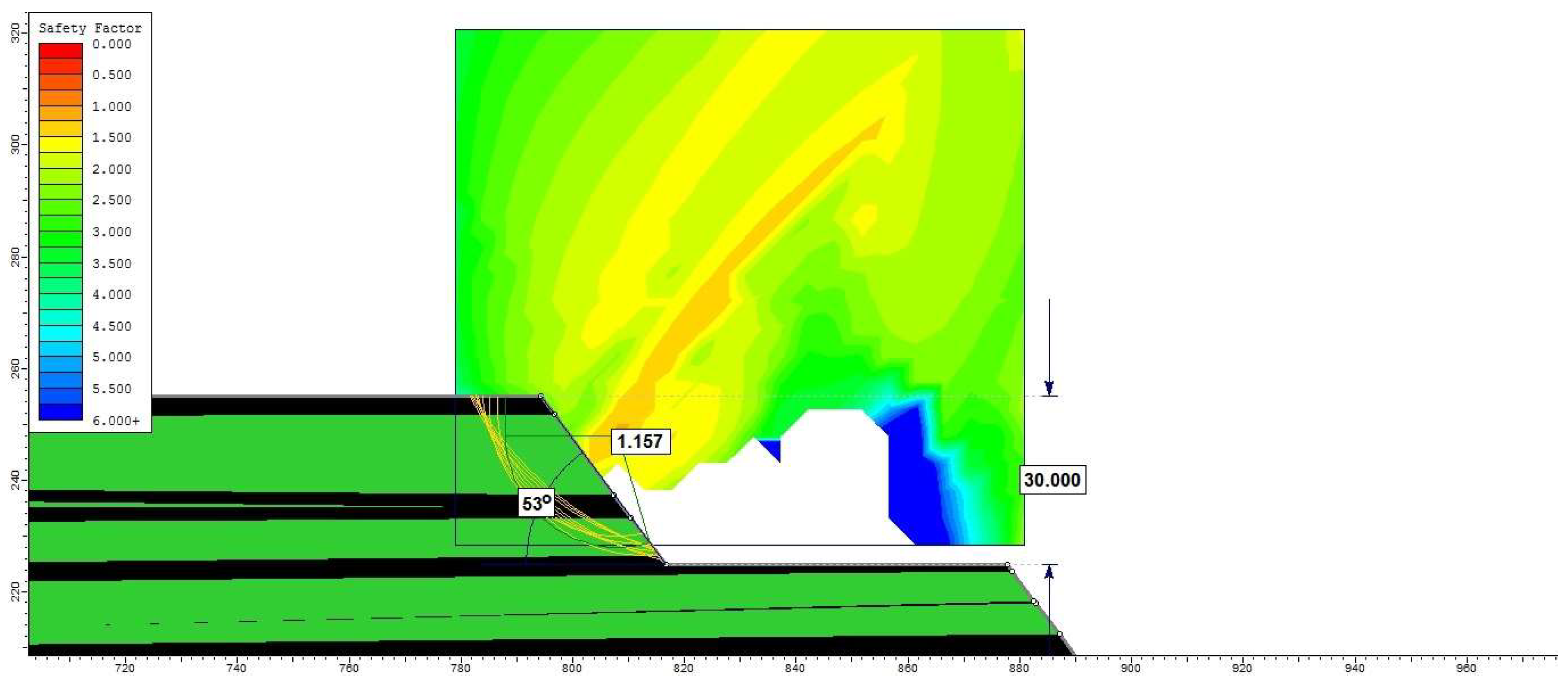
| T5 | 30 | 53 | 1.236 | 1.232 | 1.157 | The minimum surfaces materialize on a part of the slope, intersect the upper berm, and pass through the roof of lignite layer VIII (Figure 13) | |
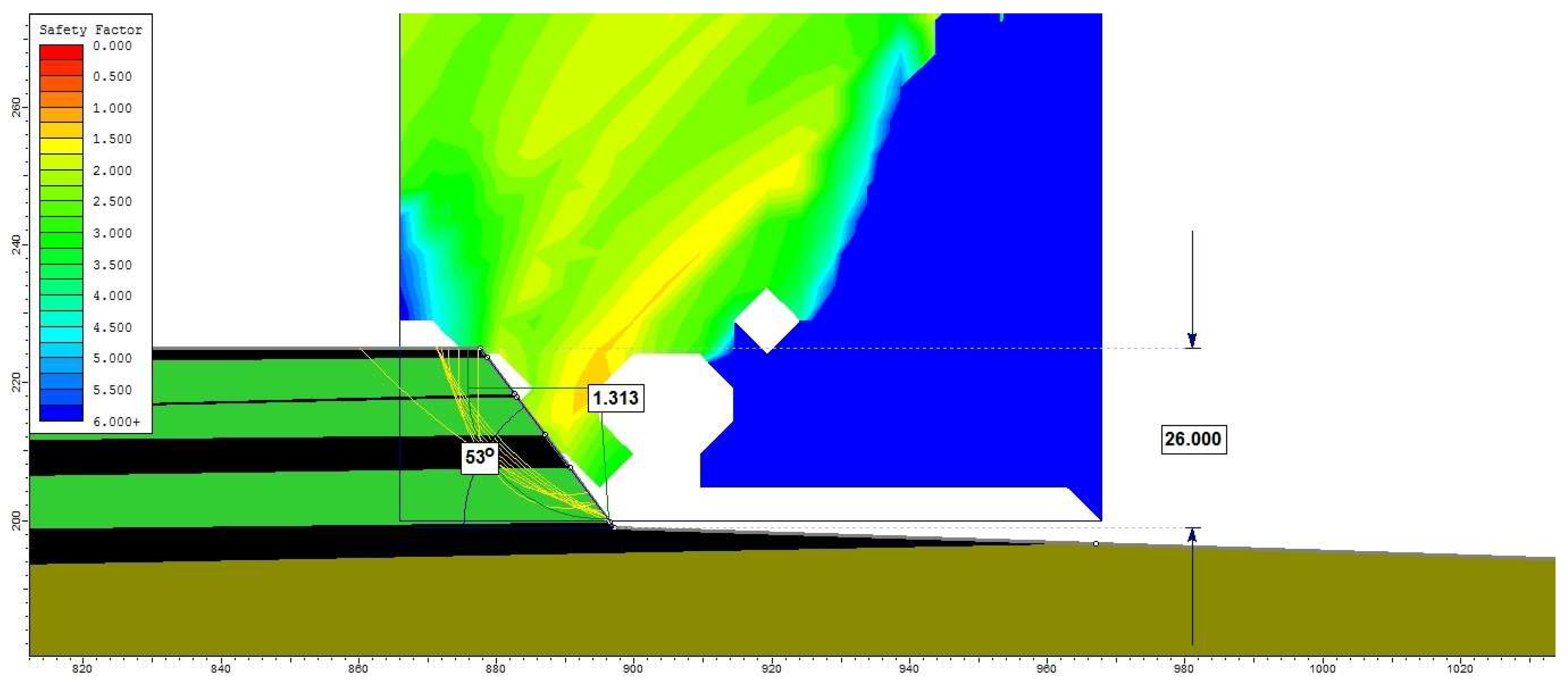
| T6 | 26 | 53 | 1.354 | 1.374 | 1.313 | The minimum surfaces materialize on a part of the slope, intersect the upper berm, and pass through the roof of lignite layer V (Figure 14) | |
| Step systems | Fellenius | Bishop | Janbu | Observations on the transmission mode of the potential sliding surface | |||
| T1–T2 | 2.559 | 2.754 | 2.460 | Intersects the sandy clays and clayey sands layers in the overburden (Figure 15) | |||
| T2–T3 | 3.516 | 3.665 | 3.430 | Passes through the base of step T3, partly through the X lignite layer and coal clays (Figure 15) | |||
| T3–T4 | 3.687 | 4.028 | 3.458 | Passes through the base of step T4, intersecting lignite layers VIII–X and coal clays (Figure 15) | |||
| T4–T5 | 3.732 | 3.795 | 3.598 | Passes through the slope of step T5, intersecting lignite layers VII–X and coal clays (Figure 15) | |||
| T4–T6 | 2.579 | 2.703 | 2.552 | Passes through the slope of step T6, intersecting lignite layers VI–X and coal clays (Figure 15) | |||
| T5–T6 | 1.995 | 2.059 | 1.947 | Passes through the slope of step T6 and through the roof of the lignite layer V (Figure 15) | |||
| General slope (all steps) | Fellenius | Bishop | Janbu | Observations on the transmission mode of the potential sliding surface | |||
| T1–T6 | 2.726 | 2.761 | 2.702 | Passes through the slope of step T6 and through the roof of the lignite layer V | |||
| Step No. | Sub-Step No. | Height H, [m] | Slope Angle α, [°] | Stability Factor (Coefficient) Fs | Observations on the Transmission Mode of the Potential Sliding Surface | ||
|---|---|---|---|---|---|---|---|
| Fellenius | Bishop | Janbu | |||||
| T1 | ST1 | 5 | 45 | 2.158 | 2.215 | 2.131 | The critical sliding surface materializes along the entire height of the slope, intersecting the upper berm of ST1 (at 3.5 m from the edge), and passing through the tip of the slope (Figure 18) |
| ST2 | 5 | 45 | 2.265 | 2.269 | 2.237 | The critical sliding surface materializes along the entire height of the slope, intersecting the upper berm of ST2 (at 1 m from the edge), and passing through the tip of the slope (Figure 18) | |
| ST3 | 15 | 40 | 1.163 | 1.204 | 1.138 | The critical sliding surface materializes along the entire height of the slope, intersecting the upper berm of ST3 (at 4 m from the edge), and passing through the tip of the slope (Figure 19) | |
| ST1–ST2–ST3 (sub-step system) | 25 | 23 | 1.803 | 1.938 | 1.751 | The critical sliding surface materializes along the entire height of the sub-step system (or T1), intersecting the upper berm of ST1 (at 5 m from the edge), and passing through the slope of ST3 (Figure 19) | |
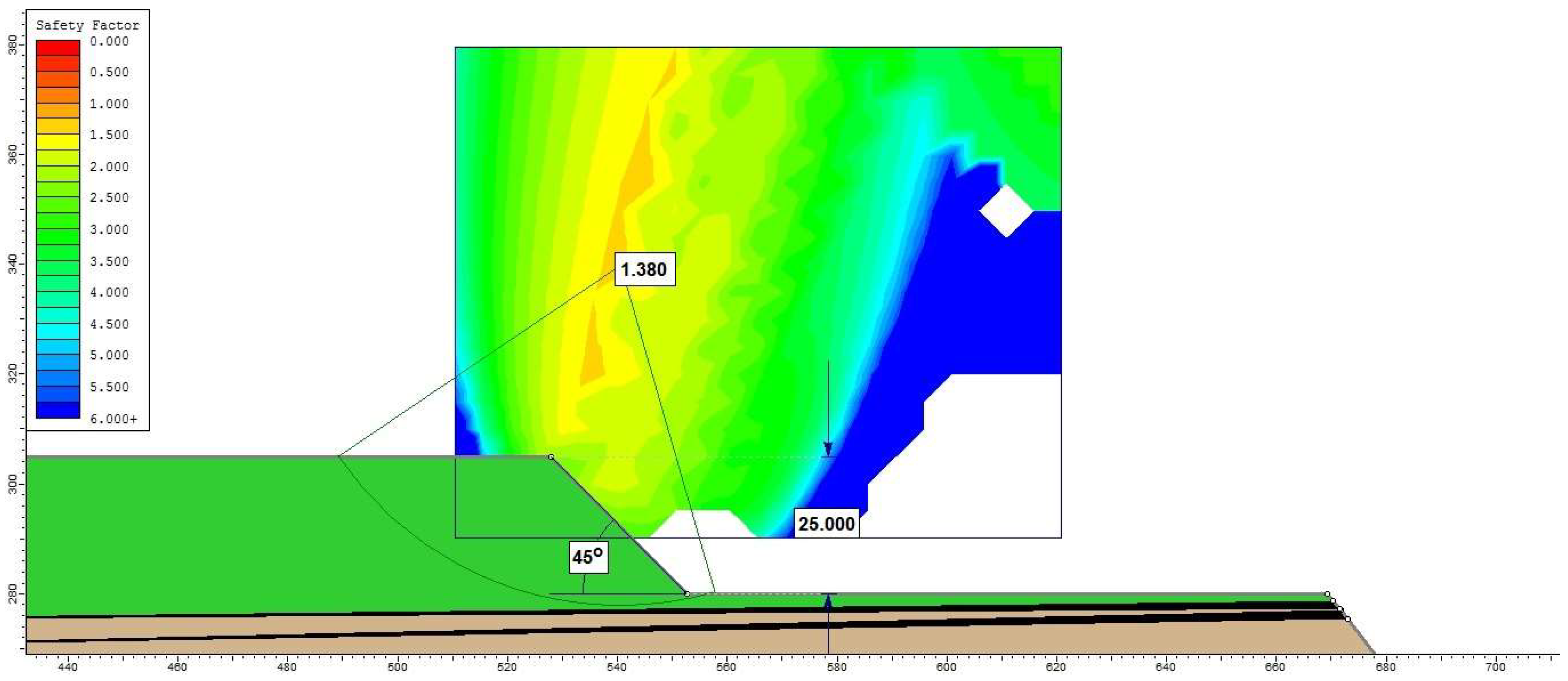
| T3 | - | 25 | 45 | 1.396 | 1.472 | 1.380 | The critical slip surface materializes over the entire height of the slope, intersecting the upper berm, and passing through the base of the slope (Figure 20) |
Disclaimer/Publisher’s Note: The statements, opinions and data contained in all publications are solely those of the individual author(s) and contributor(s) and not of MDPI and/or the editor(s). MDPI and/or the editor(s) disclaim responsibility for any injury to people or property resulting from any ideas, methods, instructions or products referred to in the content. |
© 2023 by the authors. Licensee MDPI, Basel, Switzerland. This article is an open access article distributed under the terms and conditions of the Creative Commons Attribution (CC BY) license (https://creativecommons.org/licenses/by/4.0/).
Share and Cite
Faur, F.; Lazar, M.; Apostu, I.-M.; Brujan, M. Verifying the Stability of the Working Fronts of Lignite Open Pits Developed in Hilly Areas—A Case Study of Jilț North Open Pit (Romania). Appl. Sci. 2023, 13, 11480. https://doi.org/10.3390/app132011480
Faur F, Lazar M, Apostu I-M, Brujan M. Verifying the Stability of the Working Fronts of Lignite Open Pits Developed in Hilly Areas—A Case Study of Jilț North Open Pit (Romania). Applied Sciences. 2023; 13(20):11480. https://doi.org/10.3390/app132011480
Chicago/Turabian StyleFaur, Florin, Maria Lazar, Izabela-Maria Apostu, and Mioara Brujan (Predoiu). 2023. "Verifying the Stability of the Working Fronts of Lignite Open Pits Developed in Hilly Areas—A Case Study of Jilț North Open Pit (Romania)" Applied Sciences 13, no. 20: 11480. https://doi.org/10.3390/app132011480
APA StyleFaur, F., Lazar, M., Apostu, I.-M., & Brujan, M. (2023). Verifying the Stability of the Working Fronts of Lignite Open Pits Developed in Hilly Areas—A Case Study of Jilț North Open Pit (Romania). Applied Sciences, 13(20), 11480. https://doi.org/10.3390/app132011480