Abstract
Relative phase permeability is an important characteristic of multiphase flow in porous media. Its assessment is an urgent issue when the pore structure changes due to rock dissolution. This article examines the effect of carbonate rock dissolution on two-phase flow based on images obtained by X-ray microcomputed tomography with a spatial resolution of ~18 µm. The characteristics of the two-phase flow were calculated through pore network modeling. The studies were conducted on 20 sub-volumes, which were extracted from cylindrical samples A and B with permeabilities of 0.72 and 0.29 D. HCl solutions (12% and 18%) were injected into samples A and B at a rate of 8 and 2 mL/min, respectively. Due to rock dissolution, the porosity and absolute permeability of the sub-volumes increased by 1.1–33% and 44–368%, respectively. Due to dissolution, the residual oil and water saturations decreased by 20–46% and 25–60%, respectively. These results showed that an increase in absolute permeability led to a significant reduction in residual oil and water saturations. These results also demonstrated that rock dissolution resulted in a change in the spatial heterogeneity of the relative phase permeabilities. The spatial heterogeneity increased in sample A after rock dissolution, while in sample B, it decreased.
1. Introduction
The study of the influence of the microstructure of porous materials on multiphase flow is a key topic of modern oil and gas and geological science. In the context of the constant development of oil and gas production and the need for efficient methods of capturing and sequestrating CO2, the study of the pore structure of carbonate rocks during the injection of acid solutions becomes especially relevant. Carbonate rocks are not only a key factor in the oil industry but can also contribute to environmental sustainability by capturing and sequestrating CO2.
To achieve more accurate modeling results and gain a better understanding of flow mechanisms in porous media, researchers are utilizing modern research methods. One such method is X-ray micro-computed tomography (µCT), which allows for the generation of high-resolution 3D models of the pore structure. These models, in turn, serve as the foundation for analyzing the behavior of fluids in porous media using various modeling techniques [1,2,3].
One of the key factors in the study of carbonate rocks is the analysis of changes in their pore structure under the influence of various acidic solutions, as this can significantly impact their transport properties [4,5]. Measurements of absolute and relative phase permeabilities play a crucial role in determining the efficiency of displacing one fluid (oil or gas) with another fluid (water or other agents) and in utilizing the pore structure of carbonate rocks for CO2 sequestration [4,6,7,8].
For a deeper understanding of these processes, researchers use modern modeling techniques for the computation of micro and macro parameters of porous medium. One such technique is fluid flow simulation based on pore network modeling, which allows for the analysis of fluid flow behavior in porous media at the pore scale [9,10,11,12]. Confirmation of the importance of these studies can be found in research that utilizes 3D pore models of samples and numerical modeling to investigate the influence of pore geometry on fluid flow in porous media. These results demonstrate that even minor changes in the sizes and shapes of pores can have a significant impact on flow efficiency [13,14,15,16,17]. Furthermore, studies on the effects of acid injection on the structure and properties of porous materials, as well as on the relationship between permeability and pore size, highlight the importance of considering the pore structure when analyzing fluid flow in a porous media [18,19]. This is also supported by research demonstrating the influence of pore geometric parameters on fluid flow processes [20,21].
Niu and Krevor investigated the influence of rock mineral dissolution on multiphase flow characteristics in two distinct carbonate rocks with varying pore structures [4]. They conducted experimental tests involving the dissolution of 0.5% of the mineral volume within rock cores using a temperature-controlled acidic solution. This dissolution process significantly affected the pore structure, leading to changes in relative permeability and residual trapping. The impact of rock matrix dissolution is heavily reliant on changes in the underlying pore structure. If variations in the pore structure can be observed or estimated through modeling, it should be possible to predict the effects on multiphase flow properties.
One of the key points during the injection of solutions into rock samples is the wettability change of the rocks, which can lead to more efficient oil displacement. Aziz et al. indicated that wettability alterations occurred during low-salinity water flooding [22]. According to that study, wettability alteration from a more oil-wetting to a more water-wetting condition has been obtained as one of the most notable effects of low-salinity water flooding.
An important mechanism for wettability alteration in carbonate rocks is mineral dissolution. Sagbana et al., in their critical review, indicated that the equilibrium between carbonate rock, formation water and crude oil is disturbed when low salinity water, containing more ions than formation water, was injected [23]. This leads to the dissolution of calcite and a change in the wettability of the rock surface from oil-wet to water-wet.
Drexler et al. showed that carbonated water injection led to a change in rock wettability from neutral to water-wet [24]. This change in wettability also led to a shift in the relative permeability curves and showed an increase in oil mobility after carbonated water injection.
One of the important factors influencing the characteristics of two-phase flow in porous media are pore filling and snap-off, which depend on the topology and pore sizes [25]. They can lead to trapping of the non-wetting phase, which decreases its mobility.
Mahmud and Nguyen showed a significant effect of snap-off on relative phase permeabilities and residual saturations [26]. Under highly wetting conditions, snap-off significantly reduces the relative permeability and increases the residual saturation of the non-wetting phase. In addition, snap-off shifted the intersection point of the relative permeabilities to lower saturations of the wetting phase.
Yousef et al., using nuclear magnetic resonance, demonstrated that the process of calcite dissolution is capable of increasing pore sizes and improving the connection between micro- and macropores [27]. The authors hypothesized that changes in wettability due to calcite dissolution could help increase oil production.
However, a literature review has shown that there is a gap in the study of the influence of changes in the pore structure of carbonate rocks during rock dissolution on relative phase permeabilities. This study aimed to examine the effect of changes in the pore structure of two cylindrical carbonate samples during HCl injection on relative phase permeability curves and residual saturations using µCT images and pore-scale simulations. For this purpose, 20 sub-volumes were extracted from both samples, which were scanned before and after the injection of HCl solutions using X-ray µCT with a spatial resolution of 18 µm.
2. Materials and Methods
2.1. Sample Description
For this study, two cylindrical samples (A and B) were selected from the core of one of the carbonate reservoirs of the Republic of Tatarstan. The axis of the cylindrical samples was aligned parallel to the rock layering. Subsequently, these cylindrical samples were cleaned to remove any contained oil and bitumen using an alcohol–benzene mixture in a Soxhlet apparatus until a transparent color of the reagent was obtained, which indicates the absence of hydrocarbons. Afterward, the samples were subjected to a Soxhlet apparatus with distilled water to remove any water-soluble salts and then dried at 104 °C for 24 h until the change in mass did not exceed 0.01 g.
The total porosity of the samples was determined using the liquid saturation method. The mineral composition was analyzed using a Bruker D2 Phaser X-ray diffractometer (Figure 1a), which indicated that both samples were highly homogeneous in composition, which allowed for the exclusion of any influence of the mineral composition on the rock’s dissolution by acid solutions. The characteristics of these samples are provided in Table 1.
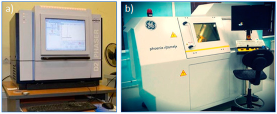
Figure 1.
(a) X-ray diffractometer and (b) X-ray computed tomography.

Table 1.
Characteristics of the samples.
2.2. Experimental Procedure
Flow-through experiments with the injection of 2% sodium chloride (NaCl) solution and hydrochloric acid (HCl) solutions were carried out using a Wille Geotechnik Y1000 electronic rock testing unit in reservoir conditions. A 2% NaCl solution was selected to replicate the characteristics of the formation water for the measurement of absolute permeability, with the intention of approximating reservoir conditions as closely as possible. HCl was employed to prepare an acidic solution for the purpose of dissolving the carbonate rock. This choice was made due to the fact that HCl is the most suitable acid for interacting with carbonate rocks, as substantiated by previous studies [16,17,28].
The experimental procedure is as follows (Figure 2). After cleaning and drying, the sample was scanned using a General Electric V|tome|X S240 X-ray µCT at a resolution of about 18 µm (Figure 1b). Then, it was saturated with 2% NaCl solution and kept for 12 h at a temperature of 20 °C and a pressure of 3 MPa (reservoir conditions).
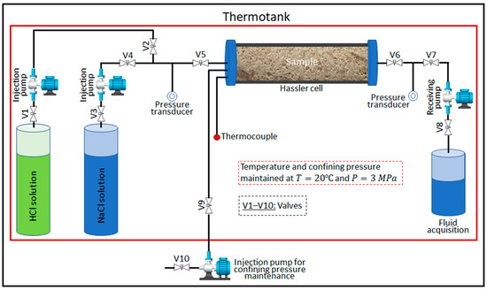
Figure 2.
Schematic of the experimental procedure.
After that, a 2% NaCl solution was injected through the sample, and the pressure drop was measured after its stabilization for at least three injection rates. Next, valves V3 and V4 were closed, and valves V1 and V2 were opened. Then, the HCl solution was injected into the sample until breakthrough. Until breakthrough, 4.2 and 2.9 pore volumes of HCl solution were required, respectively, for samples A and B. After completion of the injection of the HCl solutions, a 2% NaCl solution was injected again into the sample to measure the pressure drop throughout the sample until it stabilized. Then, each sample was dry scanned.
All experimental data were recorded on a computer. The water permeability of the samples was calculated according to Darcy’s law. All experiments were conducted at a constant temperature and confining pressure of 20 °C and 3 MPa. The injection rate and mass concentration of HCl in the solution, as well as the measured permeability of the samples before and after injection of the HCl solutions, are shown in Table 2.

Table 2.
Flow conditions of HCl solutions and measured absolute permeability.
2.3. Simulation of Two-Phase Fluid Flow
The basic principle of operation of the X-ray µCT method is to obtain a sequence of 2D X-ray images of an object. After this, this set of images is processed with Avizo software 2019.1 [29] in order to create a 3D volumetric image of the object. In this technique, the key unit that determines the resolution of a 3D model of an object is the voxel. Voxels are similar to pixels, but they operate in 3D space, allowing you to accurately determine the structure of an object. The result of 3D image reconstruction is a 3D array of voxels organized according to XYZ coordinate axes. This array is a 3D representation of the internal structure of the object, and it is used for further visualization and analysis.
Before the construction of 3D pore space, the µCT images went through several stages of image processing, which are illustrated in Figure 3. Image processing includes cropping, noise removal, and segmentation. The cropping was performed to remove unwanted edge noise. Filtering of the image was carried out to remove noise and artifacts directly within the sample. In this study, the median filter was used for noise removal. After filtering, segmentation of the pore space was performed. All operations were carried out using Avizo software.
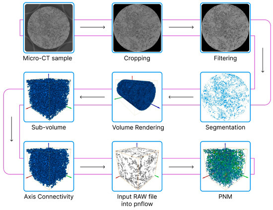
Figure 3.
Stages of processing of the µCT images.
After the image processing procedure, 3D models of both cylindrical samples were built using volume rendering (Figure 4a,b).
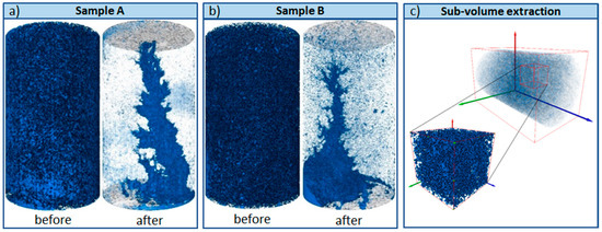
Figure 4.
Pore space of (a) sample A and (b) sample B. (c) Schematic illustration of the sub-volume extraction.
The dark blue color represents the pore space. It should be noted that the transparency of the images corresponding to the dissolved state of the samples was increased to visualize the wormholes formed due to dissolution. Also, it is important to note that the injection of acid solutions into the samples was carried out from bottom to top. As can be seen from Figure 4, as a result of rock dissolution, a dominant wormhole was formed in sample A when injecting a 12% HCl solution at a rate of 8 mL/min, whereas in sample B, a conical wormhole formed due to the comparatively low injection rate (2 mL/min), even though a more concentrated solution was used. For both samples, the injection of acid solutions led to a significant increase in their absolute permeability (see Table 2).
The initial data for the studies were cubic sub-volumes about 8 mm in size, extracted from the 3D model of each sample before and after rock dissolution (Figure 4c). The representative elementary volume (REV) selection is presented in Figure 5. As can be seen from the figure, the porosity becomes constant for a sub-volume with a volume higher than 150 mm3. The volume of extracted sub-volumes is ~83 mm3, which is larger than the REV (~63 mm3).
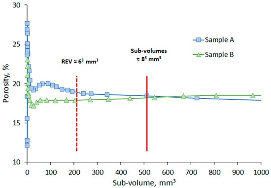
Figure 5.
Representative elementary volume selection.
In total, 10 sub-volumes were extracted from each sample, 5 before dissolution, 5 after dissolution. It should be noted that the extracted sub-volumes from the models of the same sample, corresponding to its undissolved and dissolved states, were extracted from the same location to achieve their identity. In total, 20 sub-volumes were extracted from both samples. The extraction of these sub-volumes from the samples was carried out using Avizo software. The pore space of the sub-volumes extracted from samples A and B before and after their dissolution is shown in Figure 6, where the gray color corresponds to the pore space, and white corresponds to the solid phase. As shown in Figure 6, there were noticeable changes in the pore structure of the sub-volumes as a result of rock dissolution.
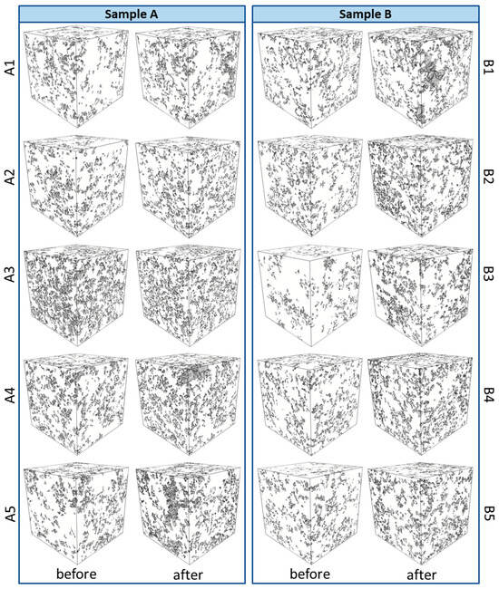
Figure 6.
Pore space (gray) of the sub-volumes extracted from cylindrical samples A and B.
Next, pore network models were extracted from the 3D pore space of the sub-volumes (Figure 3) to conduct pore network modeling of the two-phase fluid flow using the ‘pnflow’ software tool [30]. This software is based on an enhanced version of the maximal ball algorithm proposed by Dong and Blunt [31]. This method served as the basis for developing a more versatile approach to extracting porous structures, as described in [32]. Water and oil were used as wetting and non-wetting phases, respectively. During pore network modeling, connected porosity, absolute permeability, equivalent pore radius, and pore throat radius, as well as the relative phase permeabilities, were calculated. All calculations were performed using the following parameters: dynamic viscosity of oil and water—2.31 and 1 mPa·s, respectively; density of oil and water—783 and 1000 kg/m3, respectively; interfacial tension—30 mN/m; pressure drop—30 kPa; and initial contact angle—90 °C.
3. Results and Discussion
3.1. Pore Size Distribution, Porosity, and Absolute Permeability
Pore size distributions for sub-volumes from samples A and B before (blue columns) and after (orange columns) their dissolution are shown in Figure 7 and Figure 8. The equivalent pore radius was used as a characteristic size.
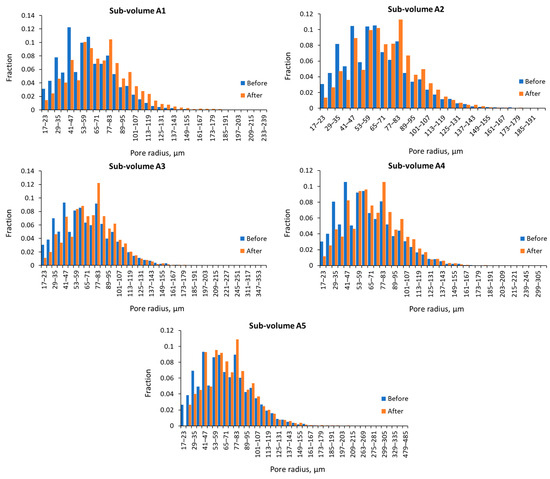
Figure 7.
Pore size distribution of sub-volumes from sample A.
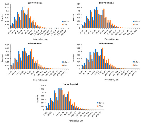
Figure 8.
Pore size distribution of sub-volumes from sample B.
As shown in Figure 7, the number of small pores (<50 µm) in all sub-volumes extracted from sample A decreased after rock dissolution. This indicates an increase in their radii due to the interaction of HCl solutions with the carbonate rock. Additionally, there was a noticeable increase in the number of large pores (those with radii greater than the average pore radii) after the rock dissolution, especially for sub-volumes A1, A2, and A4. These larger pores may have formed due to the widening of individual large pores or the merging of several small pores as a result of rock dissolution.
Despite the different conditions of acid solution injection (see Table 2), a similar situation was observed in the sub-volumes of sample B (Figure 8). However, it can be noted that there are relatively small decreases in the number of small pores (Figure 8) compared to the sub-volumes of sample A (Figure 7).
Table 3 provides a brief summary of pore statistics for the sub-volumes of both samples before and after their dissolution. As seen in this table, the lower boundary of the pore size distribution remained nearly unchanged for all sub-volumes except for sub-volume A5. In the case of A5, all interconnected small pores with radii below 23 µm disappeared as a result of rock dissolution. Furthermore, the shift of the lower boundary of the pore radius range to the right indicates that the rock dissolution did not lead to the formation of new interconnected pores with radii smaller than the original small pores. It is also worth noting that the upper boundary of the pore radius range increased for all considered sub-volumes, except A2, where it decreased by less than 5% from the initial value.

Table 3.
Brief statistics of the pore radius of sub-volumes from samples A and B.
Overall, there was a significant increase in the maximum pore radius, indicating the formation of wide channels connecting large pores as a result of rock dissolution. The average pore radius of the sub-volumes increased from 6.5 to 16.8%. The smallest and largest increases were obtained, respectively, for sub-volumes A5 and A1 (Table 3).
The effect of rock dissolution on the porosity and absolute permeability of the examined sub-volumes is demonstrated in Figure 9. The values of porosity and absolute permeability of the sub-volumes before and after their dissolution are given in Table 4. As Figure 9a shows, the porosity and absolute permeability of the sub-volumes changed differently as a result of rock dissolution. The changes in porosity and absolute permeability were relatively larger and more uniform for the sub-volumes from sample B than for the sub-volumes from sample A. Relatively large changes in porosity were observed for sub-volumes with relatively low initial porosities (see Figure 9a and Table 4). Figure 9b demonstrates the sensitivity of absolute permeability to changes in porosity, and as we can see, an increase in porosity leads to an almost linear increase in absolute permeability. This means that porosity is an important characteristic of a porous medium for assessing its absolute permeability.
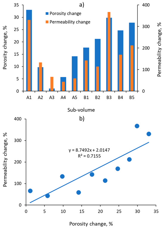
Figure 9.
(a) Porosity and absolute permeability changes of the sub-volumes and (b) the sensitivity of the absolute permeability change to porosity changes.

Table 4.
Porosity and absolute permeability of the sub-volumes from samples A and B.
3.2. Relative Phase Permeabilities
The calculated relative permeability of wetting (water) and non-wetting (oil) phases before (gray lines) and after (black lines) rock dissolution are illustrated in Figure 10 and Figure 11. As can be seen from these figures, the relative phase permeability curves changed differently during rock dissolution. In general, for all considered sub-volumes of both samples, an increase in the relative permeability of water and oil was observed as a result of the dissolution of carbonate rock (Figure 10 and Figure 11). Almost all sub-volumes, before their dissolution, could be characterized as water-wet, characterized by low relative water permeability and an almost linearly decreasing relative oil permeability with increasing water saturation.
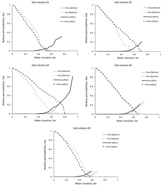
Figure 10.
Relative phase permeabilities of sub-volumes from sample A.
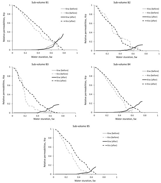
Figure 11.
Relative phase permeabilities of sub-volumes from sample B.
As Figure 10 displays, as a result of rock dissolution, a noticeable change in the relative phase permeability curves occurred in sub-volumes A2 and A3, while for the remaining sub-volumes, they practically did not change, with the exception of a slight decrease in the relative oil permeability. The significant increase in the relative water permeability of sub-volume A3 after rock dissolution may indicate a change in its wettability from water-wet to mixed-wet. Despite a noticeable increase in the relative water permeability after rock dissolution of sub-volume A3, its relative oil permeability increased significantly due to dissolution, which helped increase its mobility. Figure 10 also shows that the relative oil permeability curve of sub-volume A3 sharply decreases around the residual oil saturation.
It is noteworthy that sub-volume A3 has a relatively high initial absolute permeability, and its increase is moderate (67%) among the permeability increases of the other sub-volumes from sample A (Figure 9a). Furthermore, this sub-volume (A5) has the smallest increase (1.1%) in porosity (Figure 9a), despite having the highest initial porosity (see Table 4).
For sub-volume A2, the relative oil permeability after rock dissolution was placed higher than the pre-dissolution one for water saturations above 0.3, although the relative water permeability is still relatively low (Figure 10). Interestingly, this sub-volume (A2) had its upper boundary of the pore radius range decrease by almost 5%, whereas all other sub-volumes from both samples showed an increase (see Table 3).
Figure 11 demonstrates a significant increase in relative oil permeability after rock dissolution for sub-volumes B1 and B3–B5, which experienced substantial increases in porosity and absolute permeability (Figure 9a), while their relative water permeability shows a comparatively low increase as a result of rock dissolution.
As Figure 10 and Figure 11 illustrate, for all sub-volumes there is a significant change in critical points of the relative phase permeability curves, such as the residual oil and water saturations and the lower and upper boundaries of the range of water saturation variation, which are given in Table 5. As Table 5 describes, the residual oil saturation increased only in sub-volumes A1, A4, and A5, for which the relative phase permeabilities decreased insignificantly (Figure 10), while for the other sub-volumes, it decreased significantly.

Table 5.
Critical points of relative phase permeability curves.
As Table 5 also shows, the decrease in residual oil saturation is greater for sub-volumes of sample B than for sub-volumes of sample A. The decrease in residual oil saturation indicates that the pores have widened as a result of rock dissolution, which has led to increased oil mobility. Moreover, the widening of the range of water saturation changes in most sub-volumes as a result of rock dissolution indicates that the displacement of oil by water occurred in a relatively wide range of pore radii, and the oil in these pores was immobile before rock dissolution.
The increase in residual oil saturation for sub-volumes A1, A4, and A5 may be attributed to the formation of bypass channels as a result of rock dissolution, leading to inefficient displacement of oil from the pores. Overall, there is an observable influence of the increase in absolute permeability of sub-volumes on the residual phase saturations. The greater the increase in absolute permeability due to rock dissolution, the lower the residual phase saturations become (see Figure 12). This is particularly noticeable in the sub-volumes from sample B.
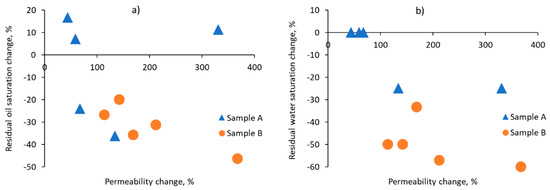
Figure 12.
Effect of changes in absolute permeability on the residual (a) oil and (b) water saturation.
Table 5 also indicates that the reduction in residual water saturation is more significant for sub-volumes from sample B compared to those from sample A.
3.3. Spatial Variability of Relative Permeabilities
Figure 11 shows graphs of the relative phase permeability curves of all sub-volumes from samples A (Figure 13a,b) and B (Figure 13c,d), respectively, before and after rock dissolution. These graphs are provided to analyze the spatial variability of the relative phase permeabilities. As can be seen from Figure 13a, before rock dissolution, sample A can be considered homogeneous in terms of relative phase permeabilities since the relative phase permeability curves of all sub-volumes from this sample are close to each other, and therefore, they can be described by single curves. This is convenient in modeling two-phase fluid flow in larger domains by considering the scaling of the endpoints of the relative phase permeability curves.
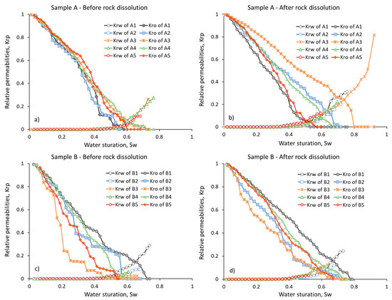
Figure 13.
Comparative graphs of the relative phase permeabilities of all sub-volumes from samples A (a,b) and B (c,d) before and after their dissolution.
Rock dissolution affected the sub-volumes of sample A differently, resulting in a redistribution of the relative oil permeability curves in space, and the relative water permeability curves are still close to each other although they have different endpoints (Figure 13b). This indicates an increase in spatial heterogeneity of fluid flow in sample A as a result of rock dissolution.
In the case of sub-volumes from sample B, there is an opposite trend (see Figure 13c,d). If, before the rock dissolution, the relative permeability curves of sub-volumes exhibited differences, after dissolution, they noticeably converged, indicating a reduction in the spatial heterogeneity of sample B. In addition, the relative oil permeability curves for sub-volumes from sample B became more linear, which could suggest a more uniform displacement of oil by water (see Figure 13d). When comparing Figure 13b with Figure 13d, we can conclude that the relative water permeability slightly changed for sample B, whereas it increased more significantly for sample A, indicating a potential change in wettability from strongly water-wet to less water-wet or even mixed-wet as a result of rock dissolution.
4. Conclusions
In this study, the influence of carbonate rock dissolution on the characteristics of two-phase fluid flow was examined based on images obtained through X-ray micro-computed tomography. Overall, the results demonstrated significant changes in the relative phase permeability of oil and water as a result of rock dissolution. Nevertheless, the following conclusions can be drawn:
Rock dissolution led to an intense decrease in the number of small pores and an increase in the number of large pores in all sub-volumes of both samples. The range of the pore radius distribution widened toward enlargement of the pores, which means the formation of new large pores, although practically no new small pores formed. The increase in the average pore radius ranged from 6.5 to 16.8% and from 6.6 to 9.1% for sub-volumes of samples A and B, respectively.
The increase in porosity and absolute permeability was higher when a more concentrated HCl solution was injected at a low flow rate compared to when a less concentrated HCl solution was injected at a high flow rate, although the initial porosity and absolute permeability were substantially smaller for the former case.
The relative phase permeability changed differently as a result of rock dissolution. The concentration of HCl and the injection rate have significant influences on the relative phase permeability. The relative phase permeability of sub-volumes A2 and A3 significantly increased due to rock dissolution, although they showed small increases in porosity and absolute permeability. In some sub-volumes, wettability changes from water-wet to mixed-wet were observed due to rock dissolution. The relative oil permeability increased for sample B, into which a more concentrated HCl solution was injected at a low rate.
Rock dissolution induced a significant decrease (20–46%) in oil residual saturation. There is a clear influence of the increase in absolute permeability on the residual oil and water saturation.
Rock dissolution led to a change in the spatial heterogeneity of the relative phase permeabilities. Sample A, which was practically homogeneous in terms of relative phase permeabilities, became heterogeneous due to rock dissolution. Conversely, for sample B, its heterogeneity decreased after rock dissolution.
Author Contributions
Conceptualization, B.K.A. and A.B.K.; methodology, B.K.A.; software, D.A.B. and K.S.U.; validation, D.A.B., A.B.K. and K.S.U.; formal analysis, D.A.B.; investigation, D.A.B.; resources, D.A.B.; data curation, B.K.A.; writing—original draft preparation, D.A.B. and A.B.K.; writing—review and editing, B.K.A.; visualization, K.S.U.; supervision, B.K.A.; project administration, A.B.K.; funding acquisition, B.K.A. All authors have read and agreed to the published version of the manuscript.
Funding
This research was funded by the Science Committee of the Ministry of Science and Higher Education of the Republic of Kazakhstan (Grant No. AP09058419) and “The APC was funded by (Grant No. AP09058419)”.
Institutional Review Board Statement
Not applicable.
Informed Consent Statement
Not applicable.
Data Availability Statement
All data used in this study can be downloaded at: https://github.com/BakhytzhanAssilbekov/Two-phase-flow-data.git.
Conflicts of Interest
The authors declare no conflict of interest.
References
- Blunt, M.J.; Bijeljic, B.; Dong, H.; Gharbi, O.; Iglauer, S.; Mostaghimi, P.; Paluszny, A.; Pentland, C. Pore-scale imaging and modelling. Adv. Water Resour. 2013, 51, 197–216. [Google Scholar] [CrossRef]
- Cnudde, V.; Boone, M.N. High-resolution X-ray computed tomography in geosciences: A review of the current technology and applications. Earth-Sci. Rev. 2013, 123, 1–17. [Google Scholar] [CrossRef]
- Sadeghnejad, S.; Enzmann, F.; Kersten, M. Digital rock physics, chemistry, and biology: Challenges and prospects of pore-scale modelling approach. Appl. Geochem. 2021, 131, 105028. [Google Scholar] [CrossRef]
- Niu, B.; Krevor, S. The Impact of Mineral Dissolution on Drainage Relative Permeability and Residual Trapping in Two Carbonate Rocks. Transp. Porous Media 2020, 131, 363–380. [Google Scholar] [CrossRef]
- Van der Land, C.; Wood, R.; Wu, K.; van Dijke, M.I.; Jiang, Z.; Corbett, P.W.; Couples, G. Modelling the permeability evolution of carbonate rocks. Mar. Pet. Geol. 2013, 48, 1–7. [Google Scholar] [CrossRef]
- Jeong, G.S.; Ki, S.; Lee, D.S.; Jang, I. Effect of the Flow Rate on the Relative Permeability Curve in the CO2 and Brine System for CO2 Sequestration. Sustainability 2021, 13, 1543. [Google Scholar] [CrossRef]
- Juanes, R.; Spiteri, E.J.; Orr, F.M.; Blunt, M.J. Impact of relative permeability hysteresis on geological CO2 storage. Water Resour. Res. 2006, 42, W12418. [Google Scholar] [CrossRef]
- Krevor, S.C.M.; Pini, R.; Zuo, L.; Benson, S.M. Relative permeability and trapping of CO2 and water in sandstone rocks at reservoir conditions. Water Resour. Res. 2012, 48, W02532. [Google Scholar] [CrossRef]
- Rodríguez de Castro, A.; Goyeau, B. A pore network modelling approach to investigate the interplay between local and Darcy viscosities during the flow of shear-thinning fluids in porous media. J. Colloid Interface Sci. 2021, 590, 446–457. [Google Scholar] [CrossRef]
- Song, R.; Liu, J.; Cui, M. Single- and two-phase flow simulation based on equivalent pore network extracted from micro-CT images of sandstone core. Springerplus 2016, 5, 817. [Google Scholar] [CrossRef]
- Yang, Y.; Wang, K.; Zhang, L.; Sun, H.; Zhang, K.; Ma, J. Pore-scale simulation of shale oil flow based on pore network model. Fuel 2019, 251, 683–692. [Google Scholar] [CrossRef]
- Zhao, J.; Qin, F.; Derome, D.; Kang, Q.; Carmeliet, J. Improved pore network models to simulate single-phase flow in porous media by coupling with lattice Boltzmann method. Adv. Water Resour. 2020, 145, 103738. [Google Scholar] [CrossRef]
- Gao, Y.; Raeini, A.Q.; Selem, A.M.; Bondino, I.; Blunt, M.J.; Bijeljic, B. Pore-scale imaging with measurement of relative permeability and capillary pressure on the same reservoir sandstone sample under water-wet and mixed-wet conditions. Adv. Water Resour. 2020, 146, 103786. [Google Scholar] [CrossRef]
- Masihi, M.; Shams, R.; King, P.R. Pore level characterization of Micro-CT images using percolation theory. J. Pet. Sci. Eng. 2022, 211, 110113. [Google Scholar] [CrossRef]
- Zhang, G.; Foroughi, S.; Raeini, A.Q.; Blunt, M.J.; Bijeljic, B. The impact of bimodal pore size distribution and wettability on relative permeability and capillary pressure in a microporous limestone with uncertainty quantification. Adv. Water Resour. 2023, 171, 104352. [Google Scholar] [CrossRef]
- Gray, F.; Anabaraonye, B.; Shah, S.; Boek, E.; Crawshaw, J. Chemical mechanisms of dissolution of calcite by HCl in porous media: Simulations and experiment. Adv. Water Resour. 2018, 121, 369–387. [Google Scholar] [CrossRef]
- Soulaine, C.; Roman, S.; Kovscek, A.; Tchelepi, H.A. Mineral dissolution and wormholing from a pore-scale perspective. J. Fluid Mech. 2017, 827, 457–483. [Google Scholar] [CrossRef]
- Steinwinder, J.; Beckingham, L.E. Role of Pore and Pore-Throat Distributions in Controlling Permeability in Heterogeneous Mineral Dissolution and Precipitation Scenarios. Water Resour. Res. 2019, 55, 5502–5517. [Google Scholar] [CrossRef]
- Yang, Y.; Li, Y.; Yao, J.; Iglauer, S.; Luquot, L.; Zhang, K.; Sun, H.; Zhang, L.; Song, W.; Wang, Z. Dynamic Pore-Scale Dissolution by CO2-Saturated Brine in Carbonates: Impact of Homogeneous Versus Fractured Versus Vuggy Pore Structure. Water Resour. Res. 2020, 56, e2019WR026112. [Google Scholar] [CrossRef]
- Bianchi Janetti, E.; Riva, M.; Guadagnini, A. Effects of Pore-Scale Geometry and Wettability on Two-Phase Relative Permeabilities within Elementary Cells. Water 2017, 9, 252. [Google Scholar] [CrossRef]
- Wu, Y.; Tahmasebi, P.; Lin, C.; Munawar, M.J.; Cnudde, V. Effects of micropores on geometric, topological and transport properties of pore systems for low-permeability porous media. J. Hydrol. 2019, 575, 327–342. [Google Scholar] [CrossRef]
- Aziz, R.; Joekar-Niasar, V.; Martínez-Ferrer, P.J.; Godinez-Brizuela, O.E.; Theodoropoulos, C.; Mahani, H. Novel insights into pore-scale dynamics of wettability alteration during low salinity waterflooding. Sci. Rep. 2019, 9, 9257. [Google Scholar] [CrossRef] [PubMed]
- Sagbana, P.I.; Sarkodie, K.; Nkrumah, W.A. A critical review of carbonate reservoir wettability modification during low salinity waterflooding. Petroleum 2023, 9, 317–330. [Google Scholar] [CrossRef]
- Drexler, S.; Hoerlle, F.; Godoy, W.; Boyd, A.; Couto, P. Wettability Alteration by Carbonated Brine Injection and Its Impact on Pore-Scale Multiphase Flow for Carbon Capture and Storage and Enhanced Oil Recovery in a Carbonate Reservoir. Appl. Sci. 2020, 10, 6496. [Google Scholar] [CrossRef]
- Singh, K.; Menke, H.; Andrew, M.; Lin, Q.; Rau, C.; Blunt, M.J.; Bijeljic, B. Dynamics of snap-off and pore-filling events during two-phase fluid flow in permeable media. Sci. Rep. 2017, 7, 5192. [Google Scholar] [CrossRef]
- Mahmud, W.M.; Nguyen, V.H. Effects of Snap-Off in Imbibition in Porous Media with Different Spatial Correlations. Transp. Porous Media 2006, 64, 279–300. [Google Scholar] [CrossRef]
- Yousef, A.A.; Al-Saleh, S.; Al-Jawfi, M. Smart water flooding for carbonate reservoirs: Salinity and role of ions. In Proceedings of the SPE Middle East Oil and Gas Show and Conference, Manama, Bahrain, 25–28 September 2011; SPE: Richardson, TX, USA, 2011. [Google Scholar]
- Fredd, C.N.; Scott Fogler, H. Influence of transport and reaction on wormhole formation in porous media. AIChE J. 1998, 44, 1933–1949. [Google Scholar] [CrossRef]
- Thermo Fisher Scientific. User’s Guide Avizo Software; Thermo Fisher Scientific: Waltham, MA, USA, 2019. [Google Scholar]
- Raeini, A.Q. Pnflow Simulation Code. Available online: https://github.com/aliraeini/pnflow (accessed on 27 January 2023).
- Dong, H.; Blunt, M.J. Pore-network extraction from micro-computerized-tomography images. Phys. Rev. E 2009, 80, 036307. [Google Scholar] [CrossRef]
- Raeini, A.Q.; Bijeljic, B.; Blunt, M.J. Generalized network modeling: Network extraction as a coarse-scale discretization of the void space of porous media. Phys. Rev. E 2017, 96, 013312. [Google Scholar] [CrossRef]
Disclaimer/Publisher’s Note: The statements, opinions and data contained in all publications are solely those of the individual author(s) and contributor(s) and not of MDPI and/or the editor(s). MDPI and/or the editor(s) disclaim responsibility for any injury to people or property resulting from any ideas, methods, instructions or products referred to in the content. |
© 2023 by the authors. Licensee MDPI, Basel, Switzerland. This article is an open access article distributed under the terms and conditions of the Creative Commons Attribution (CC BY) license (https://creativecommons.org/licenses/by/4.0/).