Abstract
The operation of the automatic emergency braking (AEB) system may lead to a significant increase in lateral offset of vehicles in curved road conditions, which can pose a potential risk of collisions with vehicles in adjacent lanes or road edges. In order to address this issue, this study proposes an integrated longitudinal and lateral control strategy for collision avoidance during emergency braking, which utilizes a control algorithm based on Time to Collision (TTC) for longitudinal control and a control algorithm based on yaw angle and preview point lateral deviation for lateral control. On one hand, the AEB system facilitates proactive longitudinal intervention to prevent collisions in the forward direction. On the other hand, the Lane Keeping Assist (LKA) system allows for lateral intervention, reducing the lateral offset of the vehicle during braking. To evaluate the effectiveness of this integrated control strategy, a collaborative simulation model involving Matlab/Simulink, PreScan, and CarSim is constructed. Under typical curved road conditions, comparative simulations are conducted among three different control systems: ➀ AEB control system alone; ➁ independent control system of AEB and LKA; and ➂ integrated control system of AEB and LKA. The results indicate that although all three control systems are effective in preventing longitudinal rear-end collisions, the integrated control system outperforms the other two control systems significantly in suppressing the vehicle’s lateral offset. In the scenario with a curve radius of 60 m and an initial vehicle speed of 60 km/h, System ➀ exhibits a lateral offset from the lane centerline reaching up to 1.72 m. In contrast, Systems ➁ and ➂ demonstrate significant improvements with lateral offsets of 0.29 m and 0.21 m, respectively.
1. Introduction
Every year, the lives of approximately 1.35 million people are cut short as a result of road traffic crashes. The road traffic safety situation is severe worldwide [1]. According to statistics from the National Safety Council of the United States, there were 32,744 fatalities due to traffic accidents in 2014, which increased to 35,398 in 2015 and further rose to 40,200 in 2017, indicating an overall upward trend in casualties [2]. Additionally, data from the South Korean National Police Agency’s investigation reported 45,921 pedestrian traffic accidents in 2019, resulting in 1487 fatalities and 46,400 injuries [3].
Advanced Driver Assistance Systems (ADASs) have experienced rapid development over the past decade, playing a crucial role in improving traffic safety [4,5]. Research indicates that comprehensive deployment of the six most common ADASs would reduce the frequency of road accidents in the UK by 23.8%, translating to a yearly reduction of 18,925 accidents [6]. In Europe, light vehicles produced after 2022 are required to be equipped with Lane Keeping Assist (LKA) and Autonomous Emergency Braking (AEB) functionalities [7]. As one crucial component of ADASs, the Autonomous Emergency Braking System (AEBS) is a vehicle control system designed to assist drivers in avoiding and reducing the severity of traffic accidents. It detects potential collisions and activates the brakes automatically without requiring the driver’s foot pedal action to initiate the braking. The LKAS alleviates the operational burden on drivers, curbing inadvertent lane departure and enhancing the vehicle’s travel safety and lateral stability [8,9,10].
In the research on the collision avoidance effects of the AEBS, Isaksson-Hellman et al. evaluated the collision mitigation effects of the automatic emergency braking system based on data reported by insurance companies. The results indicated that vehicles equipped with AEB showed a 27% reduction in rear-end collisions compared to those without the AEB system [11]. The safety benefits of AEB for a country are closely related to the market penetration rate of active safety systems. Tan et al. assessed the safety benefits of AEB in China using historical accident data and found that, compared to scenarios without AEB, with a 100% AEB penetration rate, the potential maximum reductions in deaths and injuries in China by 2030 could be 7.98% and 5.47%, respectively [12]. Furthermore, research by Fildes et al. demonstrated that vehicles equipped with AEB had a 38% lower probability of rear-end collisions compared to vehicles without AEB [13]. The study by Spicer et al. indicated that vehicles equipped with AEB systems could prevent 40% to 50% of rear-end collision accidents. The widespread adoption of AEB technology has the potential to prevent thousands of related fatalities and injury accidents each year [14]. Based on the actual data of thirty traffic accidents, it was confirmed that a total of twenty-seven accidents could have been prevented with the AEBS. Furthermore, it also demonstrated that the collision avoidance rate of vehicles gradually increased as the radar angle increased [15]. Cicchino et al. showed that low-speed AEB systems could reduce the rates of rear-end collisions and rear-end injury collisions by 43% and 45%, respectively [16]. Kullgren et al. indicated that the overall reduction in crash risk for AEB with pedestrian detection was 8%, and for AEB with bicyclist detection, it was 21% [17]. These findings underscore the significant importance of automatic emergency braking systems in collision avoidance.
In the realm of collision avoidance control algorithms, Bae et al. proposed an automatic emergency braking algorithm based on Time to Collision (TTC), which could satisfy both safety and ride comfort of a vehicle [18]. Doi et al. developed an automatic emergency collision avoidance system designed to reduce rear-end collisions. This system comprises components such as a laser radar, road estimation module, collision prediction module, and automatic braking module [19]. Fu et al. proposed an autonomous braking decision-making strategy based on Deep Reinforcement Learning (DRL), which took into account three key influencing factors including efficiency, accuracy, and passenger comfort [20]. Hang et al. introduced a rear-end Real-Time Automatic Emergency Braking (RTAEB) system, which could help successfully avoid collisions and enlarge the final headway distance. The results showed that a TTC threshold of 1.5 s and a maximum deceleration threshold of 7.5 m/s2 could achieve the best collision avoidance effect [21]. Alsuwian et al. introduced an Advanced Emergency Braking System (AEBS) with sensor fusion, which could autonomously identify a probable forward collision and activate the vehicle braking system to brake the vehicle to avoid or mitigate the collision. In addition, it incorporated a nonlinear speed controller to assist the AEBS to apply the brakes during emergency situations [22]. Xu et al. proposed an integrated Software-in-the-Loop (SIL) and Hardware-in-the-Loop (HIL) verification system to realize the rapid verification of the AEB control algorithm for a two-axle passenger car. It could verify the logic feasibility of the control algorithm through SIL testing and the implementation effectiveness of the control algorithm through HIL testing [23]. Zhang et al. proposed a dual-layer control strategy for collision avoidance during high-speed lane changes, which could track both the longitudinal and lateral trajectories well [24]. Yi et al. designed a road-adaptive collision avoidance algorithm including road friction estimation, distance warning, and braking control and its effectiveness was verified through HIL simulation testing [25]. Matsui et al. utilized incident data to identify the characteristics of dangerous traffic situations wherein vehicles turning right at intersections encountered pedestrians. This effort contributed to the pedestrian-AEB system development and the evaluation of safety systems for preventing collisions between right-turning vehicles and pedestrians at intersections [26].
Furthermore, a plethora of control strategies have been proposed by scholars worldwide for the Lane Keeping Assist System (LKAS). Dean et al. conducted a study that indicated that LDW (Lane Departure Warning) and LKA were effective in reducing the overall number of target population crashes by 3.0% ± 32% and 60% ± 16%, respectively. LKA was found to avoid more crashes than LDW because LKA begins evasive action earlier than the driver [27]. Chu et al. presented active disturbance rejection control as a solution for automated lane-keeping steering and confirmed its feasibility through experiments [28]. Liu et al. developed an end-to-end lane-keeping system including lane detection, tracking, and control components [29]. Based on the Global Navigation Satellite System (GNSS), Tominaga et al. developed LKA systems that were not affected by the surrounding environment such as weather and the lane marking [30]. Marino et al. introduced a vision-based method for automatic lane-keeping control, wherein lateral offset was used for yaw rate tracking [31]. To enhance the control accuracy of lane-keeping assistance systems for trucks encountering crosswind, Liu et al. proposed a control strategy based on a linear quadratic regulator using a path-tracking preview model [32]. Kim et al. proposed a nonlinear control of steering wheel angle using the self-aligning torque for Electric Power Steering (EPS) in the lateral control system of autonomous vehicles [33].
On average, the probability of accidents occurring on curved roads is five times higher than on straight roads [34]. Cicchino et al. analyzed rear-end collision data from 23 U.S. states during 2009 and 2016, revealing that vehicles equipped with AEB had a significantly higher likelihood of collisions when turning compared to moving straight [35]. Zhang et al. introduced a target recognition model designed to acquire road curvature and to calculate the relative lateral distances, addressing the issue of incorrect recognition in the AEB systems on curved roads [36]. Li et al. proposed a curved road collision prevention warning system based on V2X technology [37]. Lee et al. introduced a method to improve the performance of AEB systems for curves through curvilinear coordinate conversion, which was used to reflect the geometric information of roads for the navigation of an autonomous vehicle [38]. As for the research on lateral control, Lim et al. developed a model predictive control method using road geometry as constraints to allow all parts of the bus to remain within the lane during travel [39]. Li et al. developed a model-based system to activate the evasive maneuver assist function, which could help improve the driver’s steering and braking operation in a coordinated way [40]. In fact, the operation of the AEB system may cause the vehicle to move laterally out of the lane, especially when traveling on a curved path, posing potential risks of collisions with vehicles in adjacent lanes or roadside barriers [41].
In summary, there are few studies that consider both AEB and LKA simultaneously in curved road situations for intelligent vehicles. Based on this point, this paper proposes an integrated longitudinal and lateral control strategy of emergency collision avoidance for intelligent vehicles under curved road conditions, curbing the lateral offset of the vehicle during emergency braking. The lateral control is enhanced by incorporating the LKA system into the AEB system. This integration aims to suppress the lateral offset during emergency braking in curved road scenarios. To verify the effectiveness of the proposed collision avoidance strategy, a vehicle dynamics model is established using CarSim software 2020 version. A typical curved road scenario is constructed within PreScan software 2019 version, and the control algorithm is formulated using Matlab/Simulink R2022b version for joint simulation. Three different control systems are subjected to comparative testing: ➀ AEB control system alone; ➁ independent control system of AEB and LKA; and ➂ integrated control system of AEB and LKA.
The subsequent sections of this paper are outlined as follows: Section 2 introduces control objectives, examines the challenges encountered during emergency braking on curved paths, and offers potential solutions. Section 3 delivers a comprehensive elucidation of the control strategies for the AEB system, the LKA system, and three distinct control systems. Section 4 carries out a comparative simulation analysis of the three control systems across various curved radii and presents the outcomes of this comparative study. Finally, in Section 5, a summary of the entire content is provided, along with an assessment of its limitations.
2. Control Objectives
Figure 1 depicts a vehicle engaging in emergency braking on a curved road. The red phantom vehicle indicates the ego vehicle’s position during this event. Although the ego vehicle successfully avoids a collision with the stationary obstacle vehicle in the forward direction, there is a gradual increase in lateral deviation. This leads to the vehicle veering out of its original lane, potentially endangering vehicles in the opposite lane. To address this issue, this paper proposes an integrated AEB and LKA control system, which can effectively prevent collisions with obstacle vehicles ahead and also curtails the lateral offset during emergency braking in curves, reducing the risk of colliding with potential side targets.

Figure 1.
Lateral offset scenario during emergency braking on a curved road.
3. Control System Design
The overall control framework consists of three main components: the curved road driver model, the AEB control system, and the LKA control system. The curved road driver model simulates how a human driver typically manipulates the longitudinal and lateral movements of the vehicle when driving on a curved road. It provides a basis for understanding and replicating human driving behavior in the control system. When the vehicle encounters potential collision risks on the curved road, the AEB system intervenes proactively by applying emergency braking measures, to prevent rear-end collisions with the vehicle in front. The LKA system, on the other hand, is designed to curb the lateral deviation that might occur during emergency braking on curved roads, preventing the vehicle from veering out of its original lane.
Once the AEB system is activated, the LKA system can be triggered under two different conditions. Figure 2a illustrates the first control system framework, where both subsystems operate independently. Longitudinally, the AEB system actively applies braking pressure based on its designated strategy. Laterally, the LKA system determines if there is a potential lane deviation by analyzing factors such as the vehicle’s position within the lane and the direction and magnitude of deviation. If a deviation tendency is detected, the LKA system intervenes by adjusting the steering wheel angle to prevent the vehicle from veering out of the lane. If no deviation tendency is identified, the LKA system remains inactive. In contrast, the second control system framework, depicted in Figure 2b, differs in terms of the triggering mechanism for the LKA system. In this case, the LKA system is triggered when the AEB system engages emergency braking. Table 1 summarizes the functions of each control system and the corresponding triggering conditions for the subsystems.
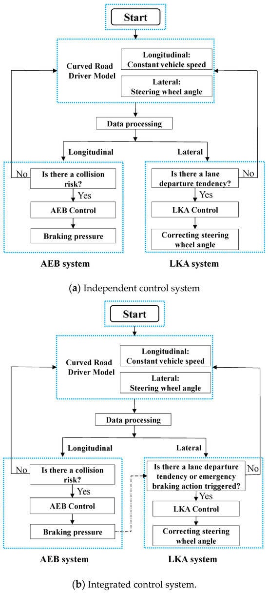
Figure 2.
Control system framework.

Table 1.
Different control systems.
3.1. Curved Road Driver Model
The curved road driver model is utilized in this study to simulate how a human driver controls the vehicle on a curved road. This model assumes a constant longitudinal vehicle speed and focuses only on the lateral control of the vehicle. The widely used pure pursuit control algorithm is used for lateral control. Figure 3 provides a simplified diagram of this model. A reference path is established along the lane centerline, starting from the vehicle’s rear axle center position A. Along this path, a preview point C is chosen by projecting it forward along the rear axle centerline for a certain distance. The steering wheel angle is then determined based on the geometric relationship among the preview distance l, the turn radius R, and the azimuth angle α of the preview point in the vehicle’s coordinate system.
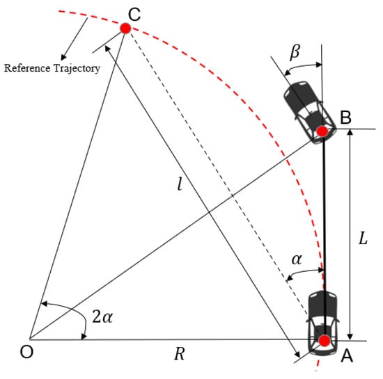
Figure 3.
Simplified diagram of pure pursuit model.
To ensure that the vehicle’s rear axle center reaches point C along the arc trajectory, △OAB must satisfy Equation (1). The front wheel steering angle can be calculated using Equation (2). By using Equations (1) and (2), the functions of and varying with time can be obtained, as shown in Equation (3). Additionally, defining the lateral error as the difference between the vehicle’s current orientation and the lateral position of the preview point, and assuming the angle in Equation (3) is small, the value of can be determined as Equation (4). Finally, the required adjustment of the steering wheel angle can be calculated through the front wheel steering angle.
To verify the effectiveness of the driver model, simulation tests are conducted when the vehicle runs on a curved road with a 90 m radius at a speed of 60 km/h. The simulation results are shown in Figure 4, where Figure 4a illustrates the variation in steering wheel angle and Figure 4b depicts the trajectory of the vehicle’s rear axle center during the tracking process. It can be observed that the steering wheel angle remains relatively constant throughout the control process, and the vehicle’s rear axle center consistently remains close to the lane centerline.
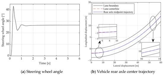
Figure 4.
Trajectory tracking control results.
3.2. AEB Control System Design
In the design of the AEB system, Time to Collision (TTC) is a crucial metric for assessing the potential danger of colliding with obstacles [42,43]. TTC can be calculated using Equation (5), where represents the relative distance between the subject vehicle and obstacle vehicles, and represents the relative velocity between the two vehicles.
Based on the calculated TTC, corresponding control strategies can be formulated. The typical AEB control logic diagram based on the TTC model is shown in Figure 5.

Figure 5.
AEB control logic.
The specific control logic is as follows:
- (1)
- TTC 2.6 s: the AEB control system not triggered;
- (2)
- 1.6 s < TTC ≤ 2.6 s: the FCW control system gives an audible alarm;
- (3)
- 0.6 s < TTC ≤ 1.6 s: the AEB control system intervenes moderately→40% braking;
- (4)
- TTC ≤ 0.6 s: the AEB control system intervenes seriously→100% braking.
3.3. LKA Control System Design
For the LKA control system, the desired target steering angle is determined based on the inputs of the vehicle’s current position and the lateral deviation at the lookahead position. These inputs are obtained from the lane detection sensor. The lane detection sensor detects the position of the vehicle relative to the lane lines. Based on this information, the system calculates the lateral deviation of the vehicle from the center of the lane at the lookahead position. The current position status of the vehicle is also taken into account to determine the desired target steering angle, considering two key variables, namely yaw angle and the difference in distance from the lookahead point to the left and right lane lines. Figure 6 illustrates a simplified diagram of the system model. In Figure 6(1), AC and BD are a pair of parallel lane detection lines separated by 4 m. The sensor’s center position is assumed to be at the centroid O, and OV represents the vehicle’s longitudinal central axis. CD can be approximated as a tangent line to the right lane arc intercepted by AC and BD. Line OE passes through centroid O and is parallel to CD, so the yaw angle α’, i.e., the angle between OV and OE, can be obtained. The sensor provides coordinates for points O, V, C, and D in the vehicle’s coordinate system. Through geometric relationships and coordinate calculations, the value of α can be calculated.
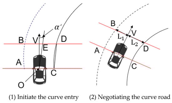
Figure 6.
Simplified diagram.
In Figure 6(2), and represent the distances from the intersection point of the vehicle’s central axis with the lane detection line CD to the left and right detection points B and D, respectively. The difference between and determines the angle β′ that needs to be adjusted for the vehicle’s center of mass to reach the lookahead point on the lane centerline. The specific calculation process is shown in Equation (6).
The ultimate desired target steering angle θ is determined by both α′ and β′, and the calculation process is shown in Equation (7), where and are proportional parameters required for converting to the steering wheel angle.
Furthermore, regarding the triggering conditions of the LKA system (independent control), whether the vehicle is deviating from the lane depends on the distance from the vehicle’s body edge on the deviation side to the lane edge on the same side. The distance serves as the criterion to ascertain if there is a tendency for the vehicle to deviate from the lane and is used as the triggering condition for the LKA system. The lane deviation scenario in curves is illustrated as Figure 7, where A and B represent the two nearest points on the deviation side, respectively. is the distance between points A and B, and it is the critical value for judging lane deviation tendency. In addition, a certain safety redundancy is considered; for example, 0.4 m selected in this study. When , it is assumed that the deviation caused by the emergency braking in curves would make the vehicle deviate from the original lane. In this case, the LKA system is triggered, adjusting the steering wheel angle to keep the vehicle’s position as close as possible to the lane centerline. Conversely, when , it is assumed that the deviation caused by the emergency braking will not make the vehicle deviate from the original lane. In this situation, the LKA system remains inactive.

Figure 7.
Lane deviation scenario.
4. Simulation and Analysis
By using a collaborative simulation platform involving Matlab/Simulink, PreScan, and CarSim, three different control systems depicted in Table 1 are validated through simulation tests. The validation process consists of constructing a collision avoidance scenario in PreScan, configuring key parameters of the test vehicle in CarSim (as listed in Table 2), and implementing the distinct control systems in Matlab/Simulink. For the constructed scenario, we set the lane width to 3.75 m and the inner radii of the lanes to 60, 90, and 120 m. The road friction is set to 0.9, and the initial distance between the host vehicle and the obstacle vehicle is 100 m. In the scenario, the obstacle vehicle remains stationary on the lane, while the host vehicle, equipped with the control systems, approaches the obstacle vehicle on the same lane at speeds of 50 km/h and 60 km/h, respectively, on the three different curved paths.
Table 2.
Main parameters of the ego vehicle.
Furthermore, prior to activating the AEB system, the vehicles are controlled using the driver model described in Section 3.1 to satisfy the lateral control requirements for normal movement on curved roads. In System ➀, it is assumed that the driver does not respond promptly after the AEB system’s warning is activated, resulting in no braking or steering actions. In terms of longitudinal control, the AEB system initiates emergency braking action. At the same time, it is assumed that the steering wheel remains unchanged during the braking process. Meanwhile, in both System ➁ and System ➂, the initial conditions remain the same, but after the AEB system is triggered, the LKA system takes over lateral control of the vehicle based on specific triggering conditions.
4.1. Curvature Radius R = 60 m
The simulation results for a vehicle running at 60 km/h on a curved road with a radius of 60 m are depicted in Figure 8. Figure 8a–d show the trajectory, distance from the center of mass to the lane centerline, steering wheel angle, and vehicle speed, respectively. Figure 8e–h display the relative distance, lateral acceleration, longitudinal acceleration, and yaw rate, respectively. Figure 9 provides a schematic representation of the simulation results for different systems in this scenario.
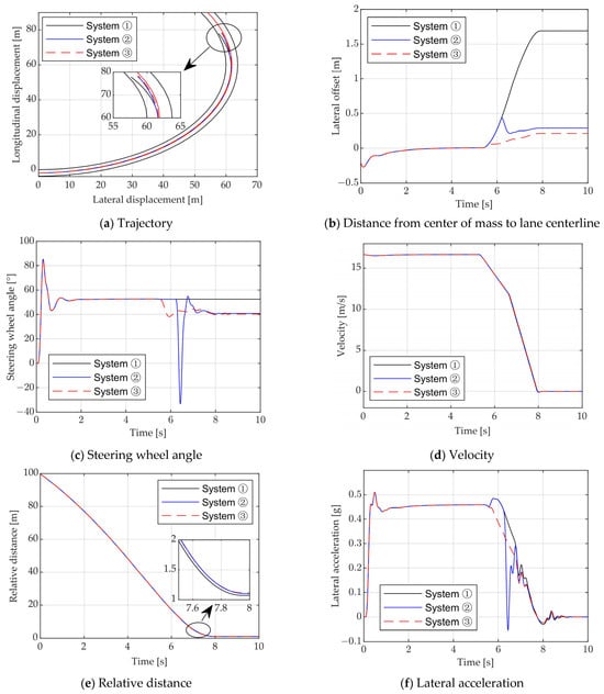
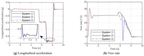
Figure 8.
Simulation results (V = 60 km/h, R = 60 m).
Figure 9.
Illustration of simulation results for different systems.
It is evident that all three control systems activate emergency braking at t = 5.6 s. The braking deceleration is increased in stages to effectively avoid a collision with the vehicle in front. By approximately t = 8.1 s, the distances between the host vehicle and the obstacle vehicle are 1.05 m, 1.11 m, and 1.15 m for Systems ➀, ➁, and ➂ respectively. Furthermore, in System ➀, the lateral offset of the vehicle’s center of mass gradually increases during emergency braking on the curved road. Eventually, at rest, the lateral offset reaches up to 1.72 m, causing the vehicle to deviate from its original lane. In System ➁, when the vehicle engages in emergency braking, the lateral offset of the center of mass also increases gradually. However, at t = 6.2 s, the system detects a tendency for the vehicle to deviate from its current lane and triggers the LKA system to make an urgent steering action. This prevents the vehicle from deviating from its original lane. At rest, the lateral displacement of the center of mass is only 0.29 m, keeping the vehicle close to the lane centerline. However, due to the emergency steering action, the vehicle’s yaw rate experiences significant changes, resulting in reduced lateral stability. In contrast, in System ➂, the LKA system is immediately triggered as the vehicle deviates laterally during emergency braking. The steering wheel is adjusted accordingly. At rest, the lateral offset of the center of mass is only 0.21 m. As the LKA system is activated earlier, the steering wheel adjustment is smaller than that of System ➁, resulting in smoother changes in yaw rate and better lateral stability.
Furthermore, simulation tests are conducted with an initial vehicle speed of 50 km/h. Table 3 presents the simulation results for two different vehicle speeds in the scenario with a 60 m radius curve. It can be observed that under both initial vehicle speeds of 50 km/h and 60 km/h, collision avoidance is achieved when the three different collision avoidance systems are triggered in the 60 m radius-curve scenario. In System ➀, there is a significant lateral offset of the center of mass during the emergency braking process. However, with the participation of the LKA system, the lateral offsets in Systems ➁ and ➂ are noticeably reduced.
Table 3.
Summary of simulation results for R = 60 m.
4.2. Curvature Radius R = 90 m
In this scenario, all other conditions remain unchanged from those described in Section 4.1, except for the curvature radius. The simulation results for the test scenario with an initial speed of 60 km/h are shown in Figure 10a–h. All three control systems avoid collision successfully, with relative distances of 1.05 m, 1.02 m, and 1.08 m. In System ➀, the lateral offset of the vehicle’s center of mass is 1.15 m when the vehicle comes to a stop. This represents a significant reduction compared to the scenario with a curvature radius of 60 m, although a portion of the vehicle’s body still deviates from the lane. In both System ➁ and System ➂, the triggering of the LKA system results in a noticeable decrease in the lateral offset of the center of mass. For System ➁, the lateral offset is 0.22 m, and for System ➂, it is 0.31 m. In both cases, the vehicle’s body remains close to the lane centerline when stationary. Furthermore, the variation in yaw rate indicates that the lateral stability of System ➂, after the LKA system is triggered, is notably superior to that of System ➁.
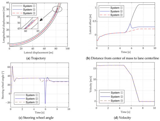
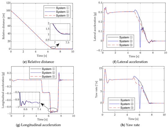
Figure 10.
Simulation results (V = 60 km/h, R = 90 m).
In addition, simulation tests are conducted with an initial vehicle speed of 50 km/h. Table 4 presents the simulation results for two different vehicle speeds in the scenario involving a 90 m radius curve. It is clear that collision avoidance is successfully achieved for both vehicle speed conditions in the 90 m radius-curve scenario with each of the three different collision avoidance control systems. With the involvement of the LKA system, Systems ➁ and ➂ demonstrate a significantly reduced lateral offset of the center of mass compared to System ➀.
Table 4.
Summary of simulation results for R = 90 m.
4.3. Curvature Radius R = 120 m
In this particular scenario, all conditions remain the same as those specified in Section 4.1, except for the curvature radius. Figure 11a–h present the results of the simulation comparison for this test scenario, where the initial speed is set at V = 60 km/h. All three control systems avoid collision successfully, maintaining distances of 1.08 m, 1.03 m, and 1.10 m to the front obstacle vehicle when stationary. In System ➀, the emergency braking process results in a lateral offset of the center of mass of the vehicle by 0.77 m. On the other hand, both System ➁ and System ➂ achieve lateral offsets of 0.25 m and 0.12 m, respectively, ensuring the vehicle body remains close to the lane centerline while stationary.
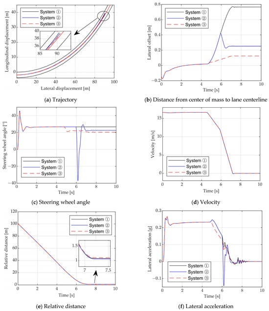
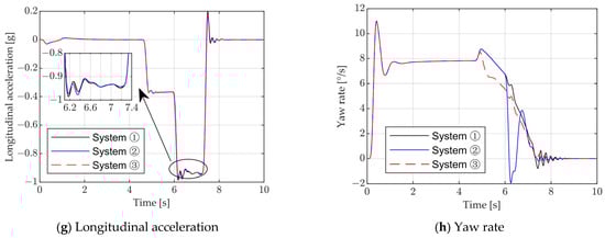
Figure 11.
Simulation results (V = 60 km/h, R = 120 m).
However, when the initial speed is decreased to 50 km/h, the vehicle’s lateral displacement is smaller, leading to the conclusion that there is no risk of deviating from the lane during the braking process in System ➁. As a result, the LKA system is not activated, resulting in the same simulation results as in System ➀. Table 5 displays the simulation results for the scenario with a curvature radius of 120 m. In this scenario, all three control systems successfully avoid collisions when activated.
Table 5.
Summary of simulation results for R = 120 m.
The simulation results above, comparing three different curve radii and two distinct initial vehicle speed conditions, clearly demonstrate the effectiveness of all three designed control systems in collision avoidance. In System ➀, where the LKA system is not engaged, a noticeable lateral offset of the center of mass is observed during emergency braking. Conversely, with the involvement of the LKA system, Systems ➁ and ➂ exhibit a substantial reduction in lateral offset, ensuring the vehicle remains closely aligned with the lane’s centerline throughout the emergency braking process. Additionally, System ➂ showcases superior lateral stability when compared to System ➁. Moreover, the lateral offset during emergency braking for System ➀ significantly decreases as the curve radius increases. However, the relationship between the lateral offset and the curve radius for the other two control systems is less pronounced.
5. Conclusions
This article proposes an integrated longitudinal and lateral control method for intelligent vehicles during emergency braking on curved roads. The purpose of this method is to effectively reduce the lateral offset of the vehicle and enhance its active safety. The proposed control method is validated through joint simulation using Matlab/Simulink, PreScan, and CarSim to simulate typical curved road scenarios. During emergency braking on curves, the existing AEB system can effectively prevent collisions with obstacles in front, but there is a risk of colliding with obstacles on the sides due to excessive lateral deviation. To address this issue, the proposed control method combines the longitudinal control by the AEB system with the lateral control by the LKA system. Three different control systems are designed for comparative simulation analysis. The results of the simulations show the following observations:
(1) In the control system without LKA system involvement, i.e., the AEB control system alone, there is a noticeable lateral offset of the vehicle during emergency braking.
(2) In the control system with LKA system participation, rear-end collisions are effectively avoided and the lateral offsets during emergency braking are reduced.
(3) The performance of the integrated control system, which triggers the LKA system immediately when the AEB system comes into action, is superior to the independent control system of AEB and LKA. In the scenario with a curve radius of 60 m and an initial vehicle speed of 60 km/h, the lateral offsets of the integrated control system, independent control system, and only the AEB control system are 0.21 m, 0.29 m, and 1.72 m, respectively.
(4) Based on these findings, it can be concluded that integrating the AEB and LKA systems leads to improved collision avoidance and reduced lateral offset during emergency braking on curved roads.
This study is limited in its focus on fixed-curvature-radius curves as the testing scenario. Future research should aim to investigate working conditions involving variable-curvature-radius curves. Furthermore, it is important to conduct additional investigation regarding passenger comfort during the collision avoidance process. Of course, experimental verification is a crucial research task in the future.
Author Contributions
Conceptualization, F.L.; methodology, formal analysis, F.L. and H.Y.; software, validation, H.Y.; writing, F.L. and H.Y.; supervision, project administration, F.L. All authors have read and agreed to the published version of the manuscript.
Funding
This work was supported by the Science and Technology Research Program of Chongqing Education Commission of China (KJQN202101105).
Institutional Review Board Statement
Not applicable.
Informed Consent Statement
Not applicable.
Data Availability Statement
Not applicable.
Conflicts of Interest
The authors declare no conflict of interest.
References
- Road Traffic Injuries. Available online: https://www.who.int/news-room/fact-sheets/detail/road-traffic-injuries (accessed on 16 July 2022).
- Sun, L.; Wu, Q.; Zhao, J.; Chen, T.; Wang, S.; Zhao, H. Empirical study on influencing factors of traffic accidents in China from 2004 to 2015. J. Southwest Univ. (Nat. Sci. Ed.) 2018, 13, 118–124. [Google Scholar]
- Kim, B.; Lee, S. A Study on the evaluation method of autonomous emergency vehicle braking for pedestrians test using monocular cameras. Appl. Sci. 2020, 10, 4683. [Google Scholar] [CrossRef]
- Viktorová, L.; Šucha, M. Drivers’ acceptance of advanced driver assistance systems—What to consider? Int. J. Traffic Transp. Eng. 2018, 8, 320–333. [Google Scholar]
- Losada, Á.; Páez, F.J.; Luque, F.; Piovano, L. Application of machine learning techniques for predicting potential vehicle-to-pedestrian collisions in virtual reality scenarios. Appl. Sci. 2022, 12, 11364. [Google Scholar] [CrossRef]
- Masello, L.; Castignani, G.; Sheehan, B.; Murphy, F.; McDonnell, K. On the road safety benefits of advanced driver assistance systems in different driving contexts. Transp. Res. Interdiscip. Perspect. 2022, 15, 100670. [Google Scholar] [CrossRef]
- Road Safety: Commission Welcomes Agreement on New EU Rules to Help Save Lives. Available online: https://ec.europa.eu/commission/presscorner/detail/en/IP_19_1793 (accessed on 15 June 2021).
- Chen, W.; Wang, W.; Wang, K.; Li, Z.; Li, H.; Liu, S. Lane departure warning systems and lane line detection methods based on image processing and semantic segmentation: A review. J. Traffic Transp. Eng. (Engl. Ed.) 2020, 7, 748–774. [Google Scholar] [CrossRef]
- Nguyen, B.; Famiglietti, N.; Khan, O.; Hoang, R.; Siddiqui, O.; Landerville, J. Testing and analysis of lane departure warning and lane keeping assist system response. SAE Int. J. Adv. Curr. Prac. 2021, 3, 2301–2316. [Google Scholar] [CrossRef]
- Peiris, S.; Newstead, S.; Berecki-Gisolf, J.; Chen, B.; Fildes, B. Quantifying the lost safety benefits of ADAS technologies due to inadequate supporting road infrastructure. Sustainability 2022, 14, 2234. [Google Scholar] [CrossRef]
- Isaksson-Hellman, I.; Lindman, M. Evaluation of the crash mitigation effect of low-speed automated emergency braking systems based on insurance claims data. Traffic Inj. Prev. 2016, 17, 42–47. [Google Scholar] [CrossRef] [PubMed]
- Tan, H.; Zhao, F.; Hao, H.; Liu, Z.; Amer, A.A.; Babiker, H. Automatic emergency braking (AEB) system impact on fatality and injury reduction in China. Int. J. Environ. Res. Public Health 2020, 17, 917. [Google Scholar] [CrossRef]
- Fildes, B.; Keall, M.; Bos, N.; Lie, A.; Page, Y.; Pastor, C.; Pennisi, L.; Rizzi, M.; Thomas, P.; Tingvall, C. Effectiveness of low speed autonomous emergency braking in real-world rear-end crashes. Accid. Anal. Prev. 2015, 81, 24–29. [Google Scholar] [CrossRef] [PubMed]
- Spicer, R.; Vahabaghaie, A.; Murakhovsky, D.; Bahouth, G.; Drayer, B. Effectiveness of advanced driver assistance systems in preventing system-relevant crashes. SAE Int. J. Adv. Curr. Prac. 2021, 3, 1697–1701. [Google Scholar] [CrossRef]
- Choi, Y.; Baek, S.; Kim, C.; Yoon, J.; Lee, S.M. Simulation of AEBS applicability by changing radar detection angle. Appl. Sci. 2021, 11, 2305. [Google Scholar] [CrossRef]
- Cicchino, J.B. Effectiveness of forward collision warning and autonomous emergency braking systems in reducing front-to-rear crash rates. Accid. Anal. Prev. 2017, 99, 142–152. [Google Scholar] [CrossRef]
- Kullgren, A.; Amin, K.; Tingvall, C. Effects on crash risk of automatic emergency braking systems for pedestrians and bicyclists. Traffic Inj. Prev. 2023, 24, S111–S115. [Google Scholar] [CrossRef]
- Bae, J.J.; Lee, M.S.; Kang, N. Partial and full braking algorithm according to time-to-collision for both safety and ride comfort in an autonomous vehicle. Int. J. Automot. Technol. 2022, 21, 351–360. [Google Scholar] [CrossRef]
- Doi, A.; Butsuen, T.; Niibe, T.; Takagi, T.; Yamamoto, T.; Seni, H. Development of a rear-end collision avoidance system with automatic brake control. JSAE Rev. 1994, 15, 335–340. [Google Scholar] [CrossRef]
- Fu, Y.; Li, C.; Yu, F.R.; Luan, T.H.; Zhang, Y. A decision-making strategy for vehicle autonomous braking in emergency via deep reinforcement learning. IEEE Trans. Veh. Technol. 2020, 69, 5876–5888. [Google Scholar] [CrossRef]
- Hang, J.; Yan, X.; Li, X.; Duan, K.; Yang, J.; Xue, Q. An improved automated braking system for rear-end collisions: A study based on a driving simulator experiment. J. Saf. Res. 2022, 80, 416–426. [Google Scholar] [CrossRef]
- Alsuwian, T.; Saeed, R.B.; Amin, A.A. Autonomous vehicle with emergency braking algorithm based on multi-sensor fusion and super twisting speed controller. Appl. Sci. 2022, 12, 8458. [Google Scholar] [CrossRef]
- Xu, J.; Li, L.; Zhao, R.; Deng, F.; Li, G. A rapid verification system for automatic emergency braking control algorithm of passenger car. Appl. Sci. 2022, 13, 508. [Google Scholar] [CrossRef]
- Zhang, S.; Liu, X.; Deng, G.; Ou, J.; Yang, E.; Yang, S.; Li, T. Longitudinal and lateral control strategies for automatic lane change to avoid collision in vehicle high-speed driving. Sensors 2023, 23, 5301. [Google Scholar] [CrossRef] [PubMed]
- Yi, K.; Woo, M.; Kim, S.; LEE, S. A study on a road-adaptive cw/ca algorithm for automobiles using hil simulations. JSME Int. J. Ser. C Mech. Syst. Mach. Elem. Manuf. 1999, 42, 163–170. [Google Scholar]
- Matsui, Y.; Oikawa, S. Characteristics of dangerous scenarios between vehicles turning right and pedestrians under left-hand traffic. Appl. Sci. 2023, 13, 4189. [Google Scholar] [CrossRef]
- Dean, M.E.; Riexinger, L.E. Estimating the Real-World Benefits of Lane departure Warning and Lane Keeping Assist; SAE Technical Paper 2022-01-0816; SAE: Warrendale, PA, USA, 2022. [Google Scholar]
- Chu, Z.; Sun, Y.; Wu, C.; Sepehri, N. Active disturbance rejection control applied to automated steering for lane keeping in autonomous vehicles. Control Eng. Pract. 2018, 74, 13–21. [Google Scholar] [CrossRef]
- Liu, M.; Deng, X.; Lei, Z.; Jiang, C.; Piao, C. Autonomous lane keeping system: Lane detection, tracking and control on embedded system. J. Electr. Eng. Technol. 2021, 16, 569–578. [Google Scholar] [CrossRef]
- Tominaga, K.; Takeuchi, Y.; Kitano, H.; Tomoki, U.; Quirynen, R.; Cairano, S. GNSS-Based Lane Keeping Assist System Using Model Predictive Control and Time Delay Compensation; SAE Technical Paper 2020-01-1023; SAE: Warrendale, PA, USA, 2020. [Google Scholar]
- Marino, R.; Scalzi, S.; Netto, M. Nested PID steering control for lane keeping in autonomous vehicles. Control Eng. Pract. 2011, 19, 1459–1467. [Google Scholar] [CrossRef]
- Liu, H.; Liu, C.; Hao, L.; Zhang, D. Stability analysis of lane-keeping assistance system for trucks under crosswind conditions. Appl. Sci. 2023, 13, 9891. [Google Scholar] [CrossRef]
- Kim, W.; Kang, C.M.; Son, Y.; Chuang, C.C. Nonlinear steering wheel angle control using self-aligning torque with torque and angle sensors for electrical power steering of lateral control system in autonomous vehicles. Sensors 2018, 18, 4384. [Google Scholar] [CrossRef] [PubMed]
- Lusetti, B.; Nouveliere, L.; Glaser, S.; Mammar, S. Experimental strategy for a system based curve warning system for a safe governed speed of a vehicle. In Proceedings of the 2008 IEEE Intelligent Vehicles Symposium, Eindhoven, The Netherlands, 4–6 June 2008; pp. 660–665. [Google Scholar]
- Cicchino, J.B.; Zuby, D.S. Characteristics of rear-end crashes involving passenger vehicles with automatic emergency braking. Traffic Inj. Prev. 2019, 20, S112–S118. [Google Scholar] [CrossRef] [PubMed]
- Zhang, L.; Yu, Z.; Xu, X.; Yan, Y. Research on automatic emergency braking system based on target recognition and fusion control strategy in curved road. Electronics 2023, 12, 3490. [Google Scholar] [CrossRef]
- Li, X.; Wu, J.; He, R.; Zhu, B.; Zhao, J.; Zhou, H. Simulation of Curved Road Collision Prevention Warning System of Automobile Based on V2X; SAE Technical Paper 2020-01-0707; SAE: Warrendale, PA, USA, 2020. [Google Scholar]
- Lee, J.; Kim, G.; Kim, B. Study on the improvement of a collision avoidance system for curves. Appl. Sci. 2019, 9, 5380. [Google Scholar] [CrossRef]
- Lim, H.; Kim, C.; Jo, A. Model Predictive Control-Based Lateral Control of Autonomous Large-Size Bus on Road with Large Curvature; SAE Technical Paper 2021-01-0099; SAE: Warrendale, PA, USA, 2021. [Google Scholar]
- Li, Y.; Petrovich, S.; Nybacka, M. Model-Based Coordinated Steering and Braking Control for a Collision Avoidance Driver Assist Function; SAE Technical Paper 2023-01-0678; SAE: Warrendale, PA, USA, 2023. [Google Scholar]
- Lai, F.; Huang, C.; Jiang, C.; Zhang, Y. Simulation analysis of automatic emergency braking system under constant steer conditions. SAE Int. J. Veh. Dyn. Stab. NVH 2022, 6, 461–476. [Google Scholar] [CrossRef]
- Coelingh, E.; Eidehall, A.; Bengtsson, M. Collision warning with full auto brake and pedestrian detection—A practical example of automatic emergency braking. In Proceedings of the 13th International IEEE Conference on Intelligent Transportation Systems, Funchal, Portugal, 19–22 September 2010; pp. 155–160. [Google Scholar]
- Han, S.; Ra, W.; Whang, I.; Park, J. Linear recursive target state and time-to-collision estimator for automotive collision warning system. In Proceedings of the IECON 2011—37th Annual Conference on IEEE Industrial Electronics Society, Melbourne, VIC, Australia, 7–10 November 2011; pp. 616–621. [Google Scholar]
Disclaimer/Publisher’s Note: The statements, opinions and data contained in all publications are solely those of the individual author(s) and contributor(s) and not of MDPI and/or the editor(s). MDPI and/or the editor(s) disclaim responsibility for any injury to people or property resulting from any ideas, methods, instructions or products referred to in the content. |
© 2023 by the authors. Licensee MDPI, Basel, Switzerland. This article is an open access article distributed under the terms and conditions of the Creative Commons Attribution (CC BY) license (https://creativecommons.org/licenses/by/4.0/).