Article

Effect of Shunt Resistor Value on the Performance of Resistive Superconducting Fault Current Limiters

1
Department of Electrical Engineering, College of Engineering, University of Ha’il, Ha’il 55476, Saudi Arabia
2
Department of Electrical Power Engineering, Faculty of Engineering, Egypt-Japan University of Science and Technology (E-JUST), Alexandria 21934, Egypt
3
Department of Electrical Power and Machines Engineering, Faculty of Engineering, Tanta University, Tanta 31511, Egypt
4
Department of Electronic and Electrical Engineering, University of Bath, Bath BA2 7AY, UK
5
Department of Mechanical Engineering, University of Bath, Bath BA2 7AY, UK
*
Author to whom correspondence should be addressed.
Appl. Sci. 2023, 13(20), 11339; https://doi.org/10.3390/app132011339
Submission received: 14 September 2023 / Revised: 12 October 2023 / Accepted: 13 October 2023 / Published: 16 October 2023
(This article belongs to the Special Issue State-of-the-Art of Power Systems)

Abstract

:
Resistive-type superconducting fault current limiters (r-SFCLs) have generated great interest for research and technical applications. This is attributed to their superior features, which include self-action, fast response, and simple operation. In low line impedance systems, r-SFCLs are seen as a viable protective mechanism for limiting high-magnitude fault currents. However, overcurrent caused by faults results in an increased temperature of the r-SFCL, possibly damaging the coils. Thus, the r-SFCL must be appropriately engineered to protect it while still allowing for effective fault current limitation. To achieve this goal, an appropriately sized shunt resistor must be used. Adding a shunt resistor benefits the r-SFCL in several ways, from lowering its maximum temperature to speeding up its recovery. Additionally, the shunt resistor protects the r-SFCL from excessive surges in temperature by giving the current an alternative path to flow down, thus saving it from further damage. A multilayer thermoelectric model was developed to examine the thermoelectrical behavior of the r-SFCL coil throughout a fault occurrence and the subsequent recovery period using three shunt resistors ranging from 4 to 16 Ω. MATLAB®/Simulink was used as the simulation platform in this study. The dependence of the current limitation capability and the voltage profile on the shunt resistor value was studied compared to the basic case without an r-SFCL. Increasing the shunt resistor value led to an enhanced ability to limit fault currents, although at the cost of higher temperatures and a longer recovery time. This study also presents guidance for optimizing the design parameters of r-SFCLs.

1. Introduction

1.1. Background and Motivation

In a highly dense electrical network, when a fault occurs near the power source where the line impedance is low, the fault magnitude will be high, which in some cases will exceed the circuit breaker (CB) rating [1]. The resistive superconducting fault current limiter (r-SFCL) is an ideal solution to deal with any high-magnitude fault currents in the presence of low line impedance in a highly dense electrical network [2]. If a fault occurs, the resistance of the r-SFCL will increase sharply due to the overcurrent and subsequent high temperature, resulting in a reduction in the fault current peak and thus enabling the CB to work safely [3]. Due to their self-acting mechanisms, fast and effective current limiting capability, and small size, r-SFCLs have garnered significant interest for academic and industrial applications. However, r-SFCLs must be properly designed to limit the fault current without excess overheating and possible damage to the coils. Using a shunt resistor is crucial to achieving this goal, as it provides an alternative path for the current, thereby reducing both the maximum developed temperature and the recovery time of the r-SFCL. The shunt resistor continues carrying the fault current until the r-SFCL fully recovers to its superconducting state. To adequately protect the r-SFCL while maintaining effective fault current limiting capability, the shunt resistor value must be carefully chosen.
The main motivation of this study was to illustrate the effect of the shunt resistor value on the r-SFCL’s performance. The r-SFCL device should reduce the fault current to below the CB rating to ensure safe operation of the CB. However, there are several constraints on the fault current limiting capability. The fault current should not be reduced to be below the pickup point of the CB; this will cause a fault detection problem, where the protective relays cannot detect the fault current. The second constraint is the thermal constraint; the temperature of the r-SFCL should not exceed the permanent damage temperature (>400 K). Testing the r-SFCL with different shunt resistors can lead to the ideal combination to deal with the constraints. The trade-off between protecting the r-SFCL and promoting its fault current limiting capability is demonstrated.

1.2. Literature Review

The “superconductivity” phenomenon was first observed in 1911 [4], and was exhibited by mercury at a critical temperature of 4.2 K. Currently, superconductivity has demonstrated success in multiple applications in power systems. Superconducting devices used in power systems include superconducting generators, motors, and cables, superconducting magnetic energy storage (SMES) systems, and SFCLs. Superconducting generators are considered to be a promising solution for two power system applications: direct-drive wind turbine generators and electric aircraft [5,6]. In ref. [7], a 3.6 MW superconducting generator was commissioned and tested as the first real-life demonstration of such generators. Meanwhile, superconducting motors are used in electrified vehicles such as electric aircraft and ships [8,9]. Superconducting cables have great potential for various applications in DC power systems despite their cost [10]. SMES systems are among the most widely used superconducting devices, with several applications in power systems including dynamic voltage restoration [11], power smoothing [12], and frequency control [13]. Finally, SFCLs have proven their effectiveness in numerous applications in power systems, such as limiting fault current contributions from distributed generating units [14], providing virtual inertia [15], and enhancing fault ride-through capability [16]. SFCLs can improve the durability of circuit breakers [17] when they are operated at lower fault current levels.
Generally, fault current limiters can be classified into two main types, superconducting and non-superconducting. During normal operation, non-superconducting FCLs have power losses, which is not desirable for the efficiency of power systems [18]. The two main types of SFCLs are resistive SFCLs (r-SFCLs) and inductive SFCLs (i-SFCLs) [18]. I-SFCLs are more complicated and heavier than r-SFCLs, and have power losses during normal operation [18,19]. For r-SFCLs, the yttrium barium copper oxide (YBCO) compound is most commonly used in the superconducting layer. During normal operation, this layer provides negligible impedance, enabling the current to flow through. When a fault occurs, the impedance of the superconducting layer increases, thus forcing part of the current to be redirected to the stabilizer layer. More details regarding power losses in FCLs can be found in [20,21].
R-SFCLs have been modeled and used in several applications to assess their performance, such as in an electric aircraft simulation environment to support the CB, where the fault magnitude is extremely high [22]. Laboratory experiments and MATLAB/Simulink simulations have been performed to understand the quench and recovery time behavior of r-SFCLs in AC systems [23]. The design of a 220 kV/150 kA r-SFCL was presented in [24]. It consisted of eight modules connected in series, each with 16 parallel bifilar coils. It was tested at its rated current in steady-state conditions and limited resistance under fault conditions, in addition to high-voltage testing. The impact of the stabilizer layer was investigated in refs. [25,26]; it was found to mainly affect the quench and recovery characteristics. In addition the impacts of stabilizer thickness, superconducting tape material, and coil geometry on the r-SFCL’s performance were investigated in ref. [27].
One of the important design considerations for r-SFCLs is determining the shunt resistor value. Adding a shunt resistor can benefit the r-SFCL in several ways, such as facilitating faster recovery and reducing the maximum temperature caused by faults. Furthermore, the shunt resistor prevents hot spot formation by redirecting the current to an alternative path, saving the r-SFCL from further damage. However, the shunt resistor will reduce the overall developed resistance of the r-SFCL, thereby reducing its fault current limiting capability. Therefore, it is important to select the appropriate value of the shunt resistor as a compromise between the fault current limiting capability and safe operation of the r-SFCL. At present, few studies have discussed the impact of the shunt resistor on the r-SFCL [2,28]. Figure 1 shows an equivalent electrical representation of an r-SFCL using AMSC-8602 superconductor tape and a shunt resistor. The AMSC-8602 stainless steel (SS) laminated tape consists of one superconducting layer (SC), a substrate (NiW), and silver (Ag) placed between two layers of stainless steel laminate, completing the tape [29].

1.3. Contribution

Based on the multilayer thermoelectric r-SFCL model in the MATLAB/Simulink environment, we investigated the impact of the shunt resistor on the performance of the r-SFCL. Few papers have investigated the effect of shunt resistors on the performance of r-SFCLs with copper stabilizers [2,26]. The modeled superconductor tape in this paper is AMSC-8602 with a stainless-steel stabilizer to ensure the highest fault current limiting capability during fault scenarios. Different shunt resistors were added to protect the r-SFCL from overheating and reduce its recovery time. The evaluated parameters were the current limiting behavior, voltage profile, and temperature profile. From the temperature profile, the maximum temperature and recovery time can be determined. Three shunt resistors were considered—low (4 Ω), medium (8 Ω), and high (16 Ω)—and the evaluated parameters were compared with those obtained without a shunt resistor. In this paper, the current was observed before, during, and after the fault clearance, and after the r-SFCL returned to its superconducting state.

1.4. Organization

After Section 1, the paper is organized as follows: The system description is discussed in Section 2. Section 3 describes the r-SFCL model in detail, including electrical and thermal modeling. Section 4 presents the simulation results obtained with various shunt resistor values. Finally, the conclusions of this study are presented in Section 5.

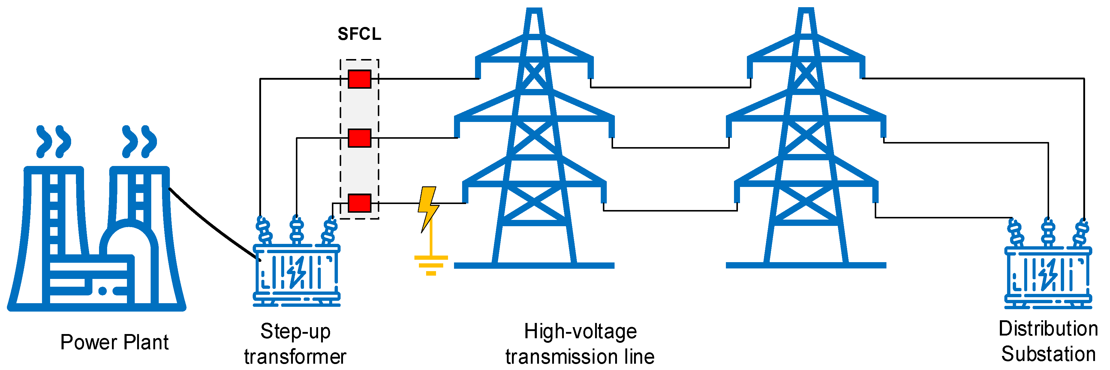
2. System Description

Figure 2 illustrates the structure of the power system under consideration for the integration of r-SFCL units in each phase. It comprises a synchronous generator, a step-up transformer, transmission lines, a distribution transformer, and loads. The r-SFCLs are installed at the beginning of the transmission lines. A solidly grounded line-to-ground fault was applied in one phase to investigate the impact of the shunt resistor on the performance of the r-SFCLs. The voltage level of the considered network was 33 kV. The line resistance of a single phase (Rcu) can be determined using (1):
    R c u = ρ c u   L A    
where ρcu is copper resistivity, L is the conductor length, and A is the conductor cross-sectional area. All simulations were performed using MATLAB®/Simulink software (MATLAB R2022b). The current flowing into the r-SFCLs and the voltage across them were then acquired. The detailed parameters of the system are shown in Table 1.

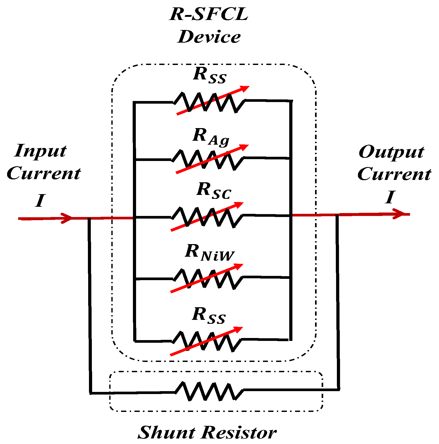
3. Superconducting Fault Current Limiter and Shunt Resistor Numerical Model

The r-SFCL devices considered in this study were used with AMSC-8602 superconducting tape, as shown in Figure 1. The tape was composed of several layers, each modeled by a current-dependent resistor. The operation of the r-SFCLs in the superconducting state was guaranteed if their current and temperature were less than the critical values for the tape. In this case, the entirety of the current flowed in the superconducting layer, which had zero resistivity. The geometry of the tape and the materials used in its construction governed its critical current and temperature.
Once a fault occurs, the current increases beyond the critical value, resulting in a sudden increase in the resistivity of the superconducting layer. As a result, the current is redistributed among the various layers of the superconducting tape and the shunt resistor. The superconducting layer resistivity (ρSC) is obtained in terms of the current density (J) as follows:
ρ S C = E c J c T ( J J c T ) N 1                                                         J > J C ,   T < T c          
where E c is the critical electrical field, J C is the critical current density, T C is the critical temperature, and N is a constant ranging between 21 and 30 [30]. The critical current density is a function of the critical temperature as follows:
J c T = J c o ( T c T t ) a ( T c T o ) a                                               T o < T < T c                
where Jco is the critical current density at the operating temperature (To), which equals 77 K in this case, and the exponent α is the density exponent, equal to 1.5 [31].
The resistivity ( ρ x ) of any other layer (x) is temperature-dependent and can be obtained from [32,33,34]. Then, the resistance of the layer itself can be obtained using (4):
R x = ρ x   l A x    
where l is the tape length and A x is the layer’s cross-sectional area. The total resistance of the r-SFCL and the shunt resistor can now be determined using (5):
1 R S F C L = 1 R Y B C O + 1 R S S + 1 R A g + 1 R N i W + 1 R S h u n t   R e s i s t o r  
The electrical representation of the r-SFCL, which contains YBCO, stainless steel, silver, and NiW layers, in addition to the shunt resistor, is given in (5).
The dependence of the electrical resistivity of each layer on temperature differs based on the temperature coefficient of the layer’s material. Consequently, it is important to precisely calculate the temperature of the r-SFCL. The temperature of the superconductor tape can be obtained as follows:
T t = T o + 1 C p   0 t Q s c t d t
where Cp is the heat capacity of the superconducting material and Qsc is the net power of the tape, which is given by the difference between the power dissipated in the tape (Pdiss) and the cooling power (Pcooling) calculated as follows:
Q s c t = P d i s s t P c o o l i n g t  
Pdiss (t) and Pcooling (t) are calculated by (8) and (9), respectively:
P d i s s t = i t 2 R s c t  
P c o o l i n g t = h A T t T o  
where A is the area exposed to the LN2 coolant and h is the heat transfer coefficient. To increase the exposure area, individual superconducting tapes and coils are separated to allow the LN2 coolant to permeate between the tapes [35,36]. We used AMSC-8602 superconducting tape from the American Superconductor Company (Ayer, MA, USA) [29], and the specifications are listed in Table 2. It has a width of 12 mm, a length of 300 m, and a critical current of 241 A.

4. Simulation Results and Discussion
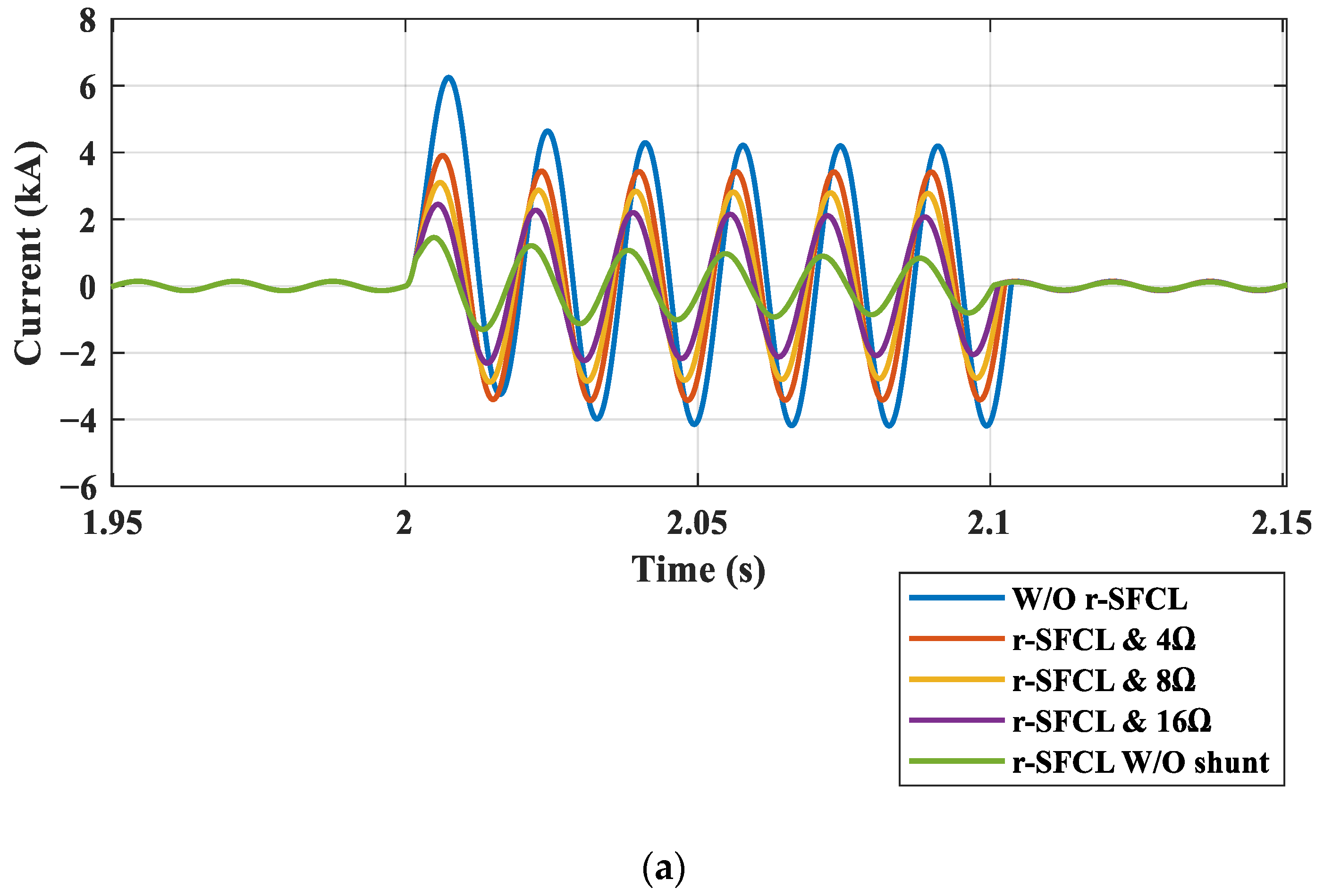
The architecture of the considered power system, illustrated in Figure 2, was modeled in the MATLAB®/Simulink environment to explore the fault behavior of a single line-to-ground fault with an r-SFCL using different shunt resistors. The fault was located at a distance of 10 km from the substation, corresponding to a total transmission line resistance of 0.6 Ω per phase.
Several case studies were investigated to assess the impact of the shunt resistors, including 4, 8, and 16 Ω shunt resistors, and one case study without a shunt resistor. The fault was applied at the time point of 2.0 s and cleared after 100 ms. In order to showcase and study both the behavior of the faults in the system as well as the system’s response, including the r-SFCL, the protection system was suppressed.

4.1. Case Studies

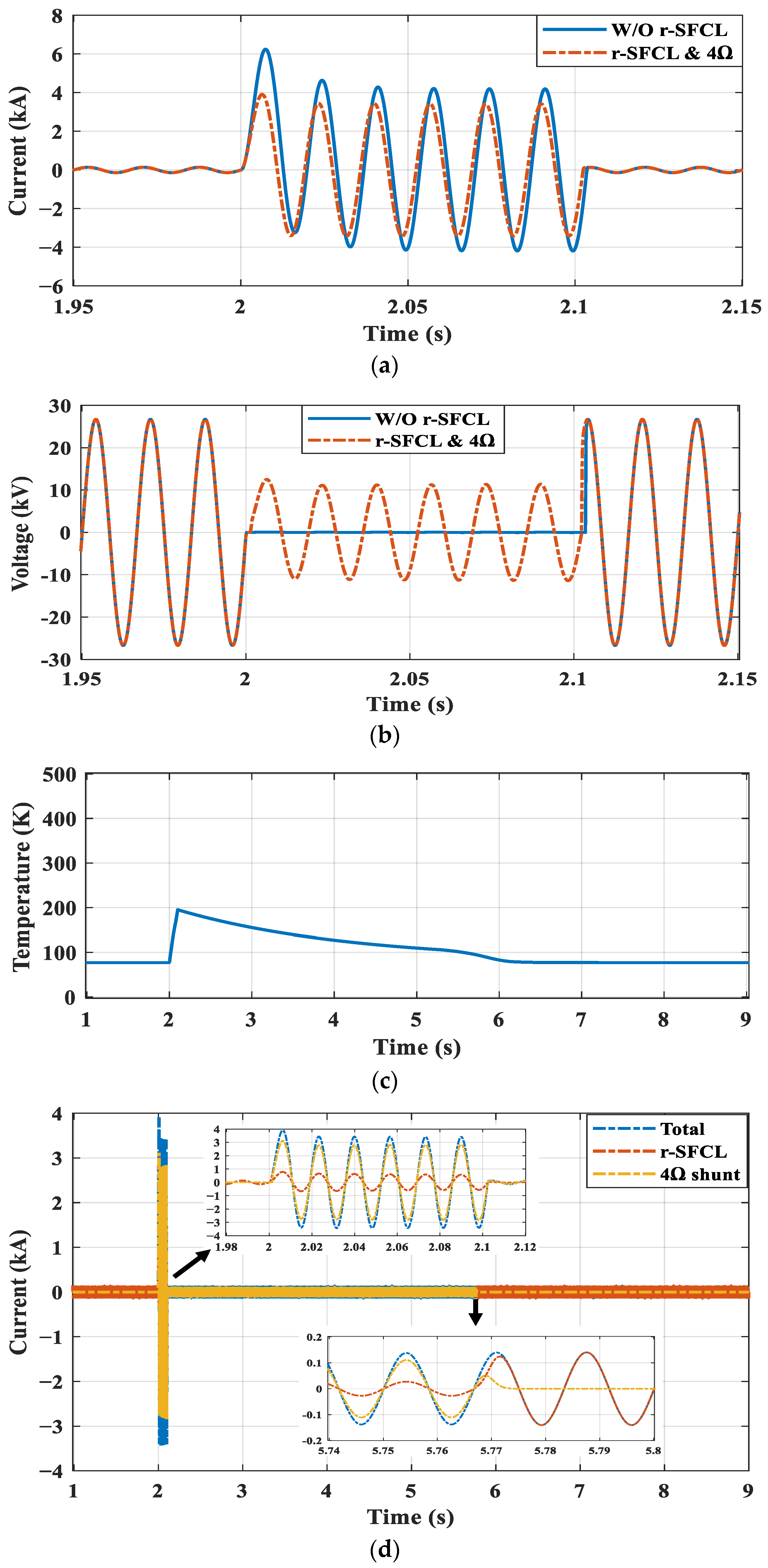
4.1.1. Case Study 1 (4 Ω Shunt Resistor)

In this case, the shunt resistor was set to 4 Ω. The fault current and corresponding voltage profile of the single line-to-ground fault are depicted in Figure 3. Without using the r-SFCL, the current exhibited first and second peak values of 6.25 and 4.64 kA, respectively. However, the r-SFCL with a 4 Ω shunt resistor could limit these values to 3.9 and 3.44 kA, respectively, representing a reduction of 37.6% for the first peak. The voltage dropped to about 8.061 kVrms when using the 4 Ω shunt resistor, compared to zero without the r-SFCL.
The temperature of the r-SFCL is shown in Figure 3c. The temperature peaked at 195 K in this case study. The r-SFCL completely recovered 3.77 s after the fault occurred, i.e., at T = 5.77 s, and returned to the coolant boiling temperature of 77 K. Before the fault occurred, the current passed through the r-SFCL while the shunt resistor’s current was zero, as shown in the current distribution in Figure 3d. After the fault occurred, the temperature increased, and the r-SFCL’s resistance increased in turn, resulting in most of the current passing through the shunt resistor, leaving a small fraction to still pass through the r-SFCL. When the r-SFCL fully recovered at T = 5.77 s, its total current flow returned, with zero current flowing through the shunt resistor.

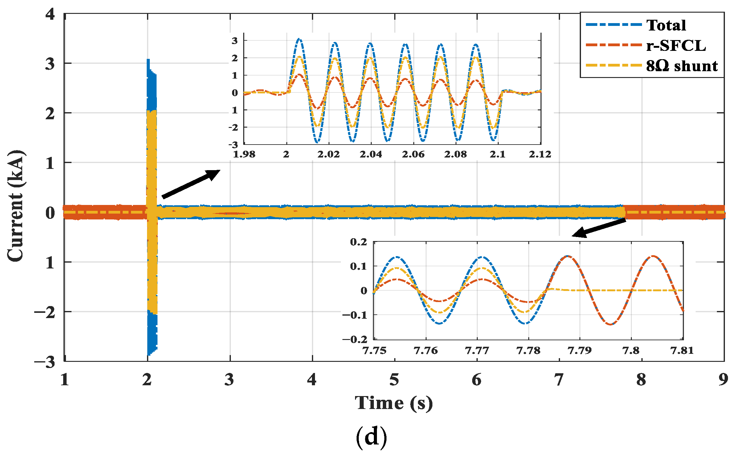
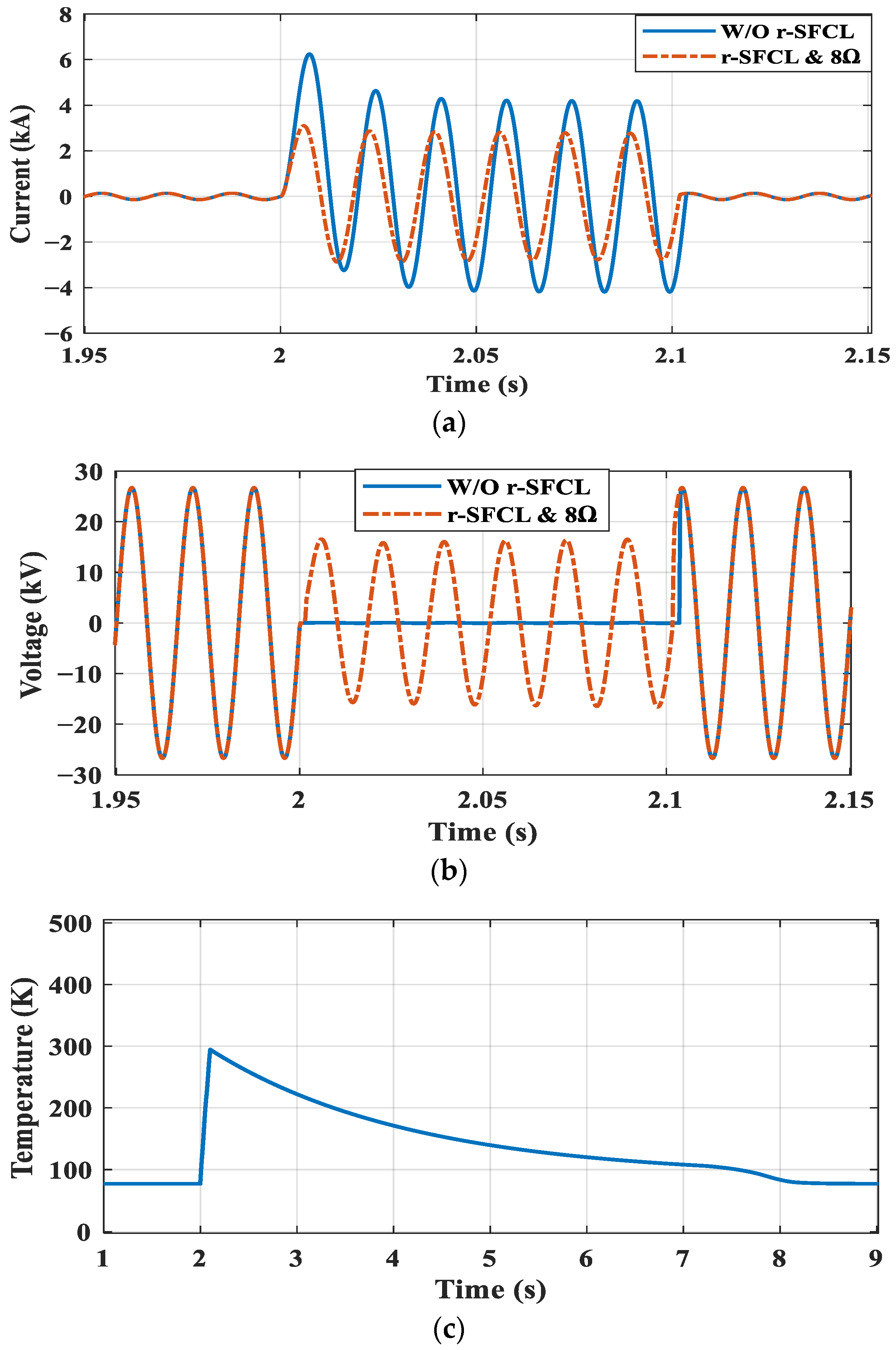
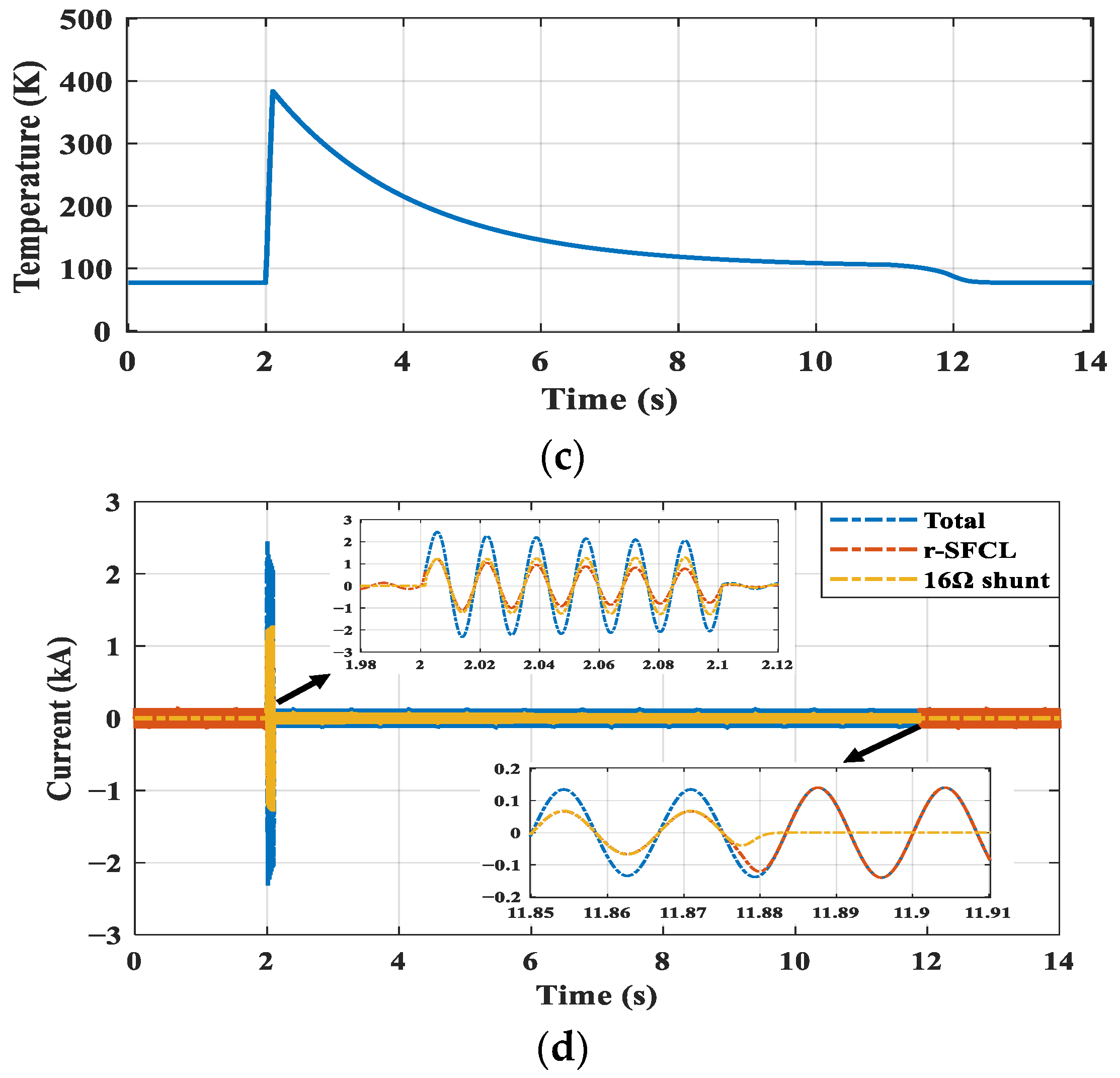
4.1.2. Case Study 2 (8 Ω Shunt Resistor)

In this case, the shunt resistor was set to 8 Ω. The fault current and the corresponding voltage profile of the single line-to-ground fault are depicted in Figure 4. The r-SFCL with the 8 Ω shunt resistor limited the fault current to 3.1 and 2.87 kA for the first and second peak, respectively, representing a reduction of 50.4% for the first peak compared to the case without an r-SFCL. The voltage dropped to about 11.59 kVrms. Looking at the previous case study, it is clear that increasing the shunt resistor increased the percentage limitation of the fault current and decreased the associated voltage drop.
The r-SFCL’s temperature is shown in Figure 4c; it reached 294 K at its peak in this case study. The r-SFCL completely recovered at T = 7.78 s, 5.78 s after the fault occurred, and returned to the coolant boiling temperature of 77 K. The r-SFCL needed more time to fully recover in this case than in the previous case, taking 5.78 s compared to 3.77 s with the 4 Ω shunt resistor. Before the fault occurred, the current only flowed through the r-SFCL and no current flowed through the shunt resistor, as shown in the current distribution in Figure 4d. After the fault occurred, both the temperature and the r-SFCL’s resistance increased, causing most of the current to flow through the shunt resistor, while the remaining current still flowed through the r-SFCL.

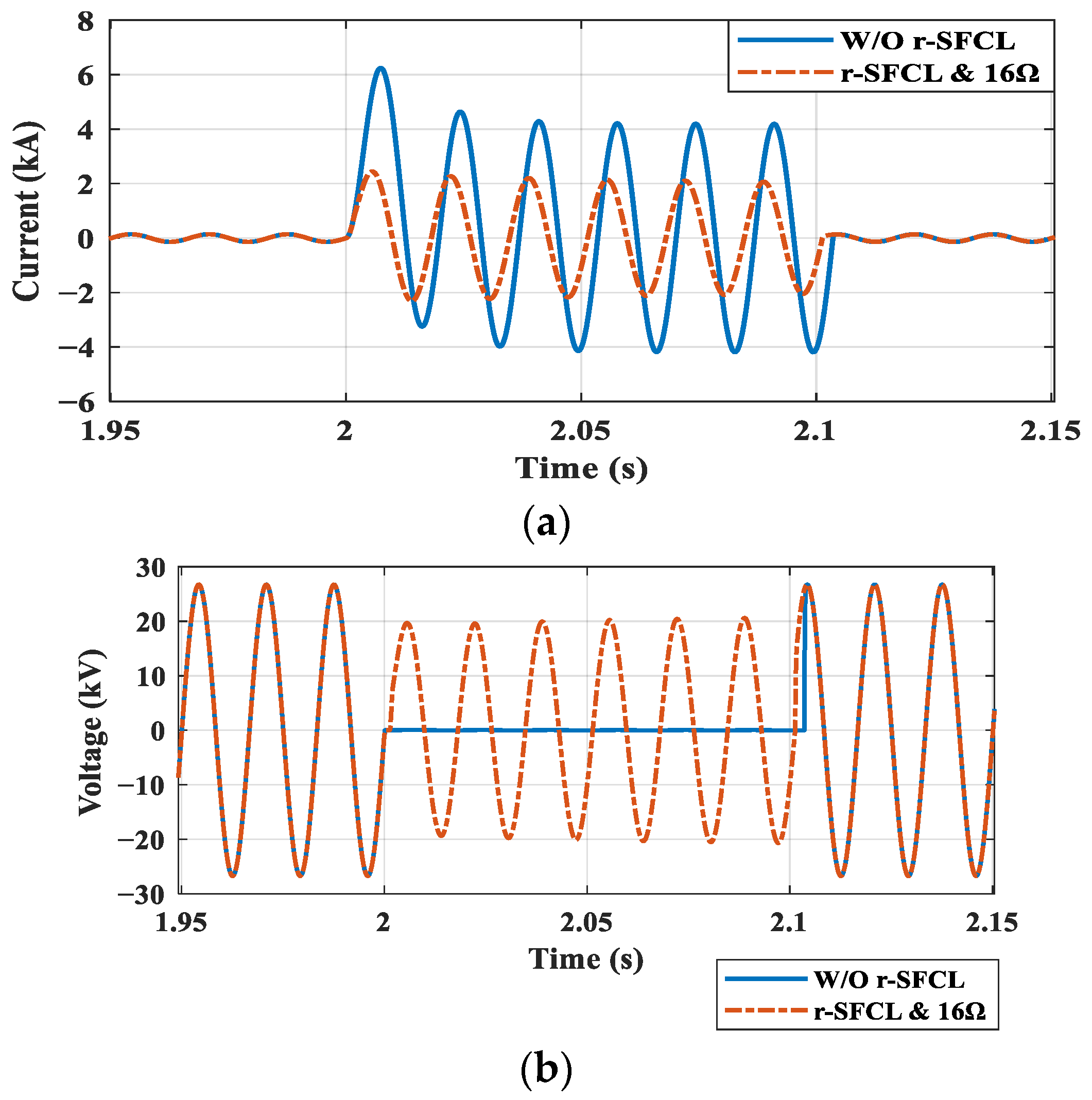
4.1.3. Case Study 3 (16 Ω Shunt Resistor)

In this case, the shunt resistor was set to 16 Ω. The fault current and corresponding voltage profile of the single line-to-ground fault are depicted in Figure 5. The r-SFCL with the 16 Ω shunt resistor was able to limit the fault current to 2.44 and 2.27 kA for the first and second peaks, respectively, representing a reduction of 60.96% for the first peak compared to the case without the r-SFCL. The voltage dropped to about 14.49 kVrms in this case.
The temperature of the r-SFCL is shown in Figure 5c; it exhibited a peak temperature of 384 K in this case study. The r-SFCL completely recovered about 9.88 s after the fault occurred, meaning that it returned to the expected coolant boiling temperature of 77 K at T = 11.88 s. Note that the recovery time in this case was significantly longer than in the previous cases using the 4 and 8 Ω shunt resistors. Before the fault occurred, all current passed through the r-SFCL while the shunt resistor’s current was zero. After the fault occurred, the temperature increased, which in turn increased the r-SFCL’s resistance, resulting in a significant portion of the current passing through the shunt resistor while the remainder still passed through the r-SFCL. Both observations can be validated by examining the current distribution shown in Figure 5d.

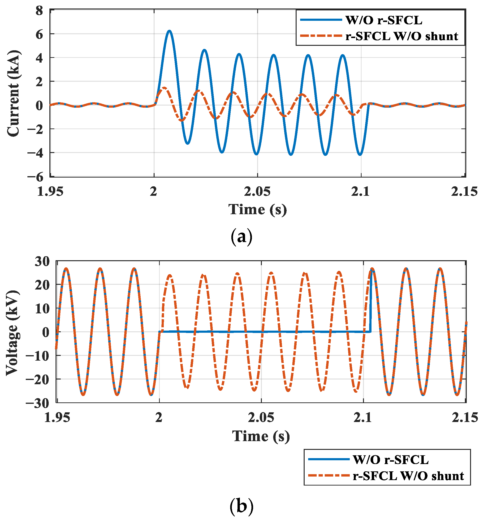
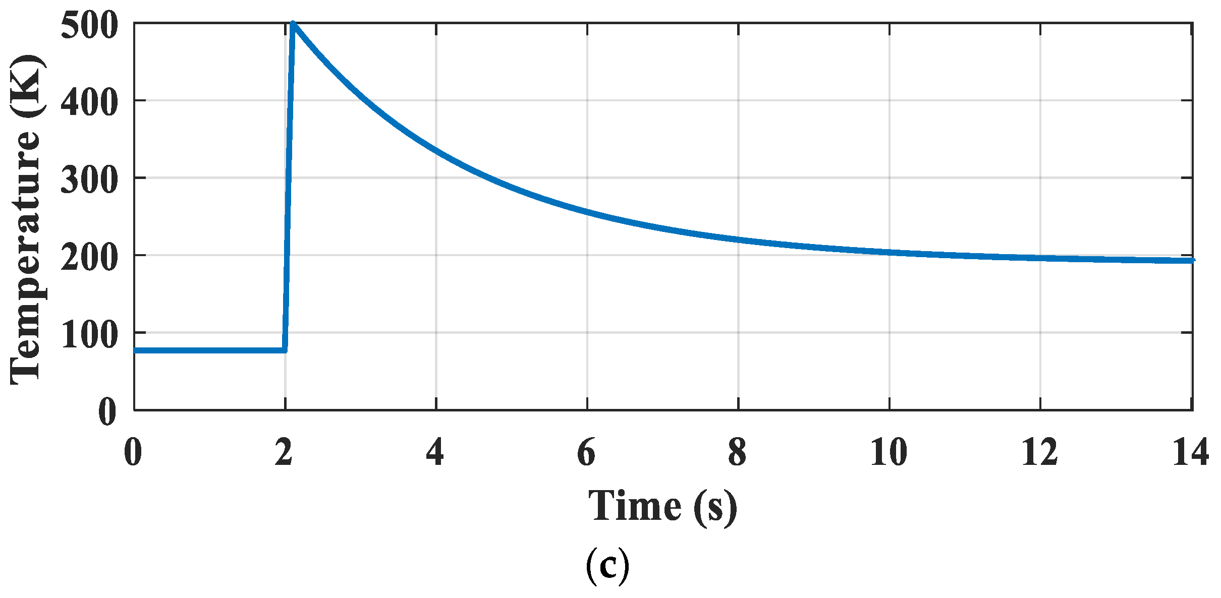
4.1.4. Case Study 4 (Without Shunt Resistor)

This case study investigated the system’s behavior without a shunt resistor. The fault current and corresponding voltage profile of the single line-to-ground fault are depicted in Figure 6. The r-SFCL without a shunt resistor could limit the fault current to 1.45 and 1.2 kA for the first and second peak, respectively, representing a reduction of 76.8% for the first peak compared to the case without the r-SFCL. The voltage dropped to about 14.43 kVrms. The r-SFCL’s temperature is shown in Figure 6c; the maximum temperature reached in this case study was 499 K. The r-SFCL did not recover, because the heat generated by the fault was equal to the coolant energy of 190 K at 14 s.

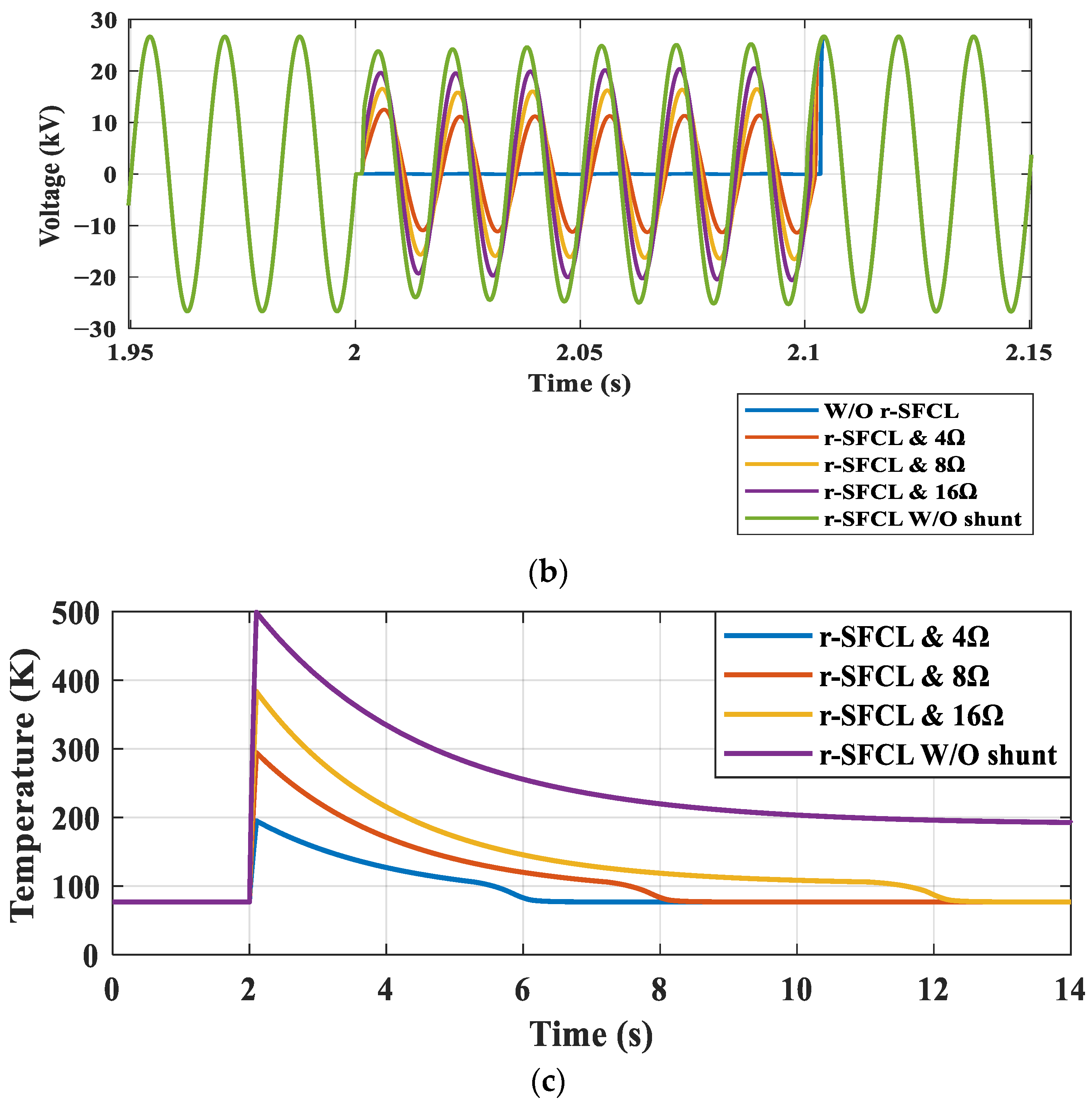
4.2. Discussion and Comparison

The fault current was effectively limited by the r-SFCL in all investigated case studies. To understand the effect of shunt resistor values on the performance of r-SFCLs during fault scenarios, Figure 7a shows the fault currents in all cases, Figure 7b shows the corresponding voltage drops, and Figure 7c shows the temperatures of the investigated r-SFCLs. Table 3 summarizes the performance indices obtained from these studies.
In terms of the fault current limiting capability, the r-SFCL without a shunt resistor had the best performance, as shown by the green line in Figure 7a. However, this meant that its temperature reached 499 K, as shown by the purple line in Figure 7c, which was the highest temperature seen in all cases (>400 K) and put the r-SFCL at the highest risk of damage.
Among the other three cases, the r-SFCL with the 16 Ω shunt resistor exhibited the best current limiting capability, with a current peak of 2.44 kA, while it remained within acceptable temperature limits and avoided permanent damage, reaching 384 K. The associated voltage drop was also the lowest of the three at 14.49 kVrms. Meanwhile, the worst current limiting capability was observed with the 4 Ω shunt resistor, leading to the highest current peak of the three at 3.9 kA (62.4% of the prospective current) and the lowest system voltage at only 8.061 kVrms, as shown in Figure 7a,b, respectively. However, this also resulted in the lowest r-SFCL temperature of 195 K, as shown in Figure 7c.
Based on Figure 7a–c and Table 3, there was a clear trade-off between the value of the shunt resistor, the fault current limiting ability, and the temperature of the r-SFCL. The higher the shunt resistor value, the higher the fault current limiting capability, but the higher the temperature, such as in case 3 (16 Ω shunt resistor).

5. Conclusions

In this study, the performance of an r-SFCL was investigated while considering the effects of different shunt resistor values. Without the r-SFCL, the fault current reached a peak of 6.25 kA. The r-SFCL with the 4 Ω shunt resistor could limit the fault current to 3.9 kA, representing 62.4% of the prospective current. On the other hand, the 16 Ω shunt resistor further reduced the fault current to 39% of the prospective current (only 2.44 kA). There was a clear trade-off between the shunt resistor value, the fault current limiting capability, and the developed temperature. When the shunt resistor value was the largest, the fault current limiting capability was the maximum, but the temperature was the highest. The main goal of using an r-SFCL device is to reduce the fault current to below the CB rating to ensure safe operation of the CB. However, there are several constraints on the fault current limiting capability. The fault current should not be reduced to below the pickup point of the CB; this will cause a fault detection problem where the protective relays cannot detect the fault current. The second constraint is the thermal constraint; the temperature of the r-SFCL should not exceed its permanent damage temperature (>400 K). As a result, the r-SFCL should reduce the fault current to below the CB rating but above the CB pickup point, and the r-SFCL temperature should be maintained below 400 K. Testing the r-SFCL with different shunt resistors can lead to the ideal combination to deal with the constraints. Based on the results, the shunt resistor value strongly affects the performance of the r-SFCL. The proper shunt resistor value should be selected to effectively limit fault currents while maintaining the safe operation of the r-SFCL. In this paper, the r-SFCL is constructed using AMSC-8062 superconductor tape. The AMSC-8062 superconductor tape has been modeled carefully with all parameters sourced from experimental works. The temperature-dependent resistivities of all layers, dissipated power, cooling power, and heat capacities (Cp) for all layers have been implemented in the model. The system has been carefully modeled to provide accurate results and to build a strong base for future work, which would be constructing an experimental prototype to practically investigate the effect of shunt resistors on r-SFCLs based on AMSC-8062 superconductor tape.

Author Contributions

Conceptualization, H.A., X.P. and D.-E.A.M.; methodology, H.A., M.K. and I.A.; software, H.A. and M.K.; validation, X.P., X.Z. and D.-E.A.M.; formal analysis, H.A., A.A. and M.A.; resources, H.A.; writing—original draft preparation, H.A.; writing—review and editing, D.-E.A.M., X.P., M.A., A.A., M.K., I.A. and X.Z; supervision, X.P. and D.-E.A.M. All authors have read and agreed to the published version of the manuscript.

Funding

This research has been funded by the Scientific Research Deanship at the University of Ha’il, Saudi Arabia, through project number RG-21 087.

Institutional Review Board Statement

Not applicable.

Informed Consent Statement

Not applicable.

Data Availability Statement

Not applicable.

Conflicts of Interest

The authors declare no conflict of interest.

References

  1. Razavi, S.-E.; Rahimi, E.; Javadi, M.S.; Nezhad, A.E.; Lotfi, M.; Shafie-Khah, M.; Catalão, J.P. Impact of distributed generation on protection and voltage regulation of distribution systems: A review. Renew. Sustain. Energy Rev. 2019, 105, 157–167. [Google Scholar] [CrossRef]
  2. Tan, X.; Ren, L.; Liang, S.; Tang, Y.; Xu, Y.; Shi, J.; Li, Z. Analysis of R-SFCL with Shunt Resistor in MMC-HVDC System Using Novel R-Q Method. IEEE Trans. Appl. Supercond. 2020, 30, 5601405. [Google Scholar] [CrossRef]
  3. Shen, B.; Chen, Y.; Li, C.; Wang, S.; Chen, X. Superconducting fault current limiter (SFCL): Experiment and the simulation from finite-element method (FEM) to power/energy system software. Energy 2021, 234, 121251. [Google Scholar] [CrossRef]
  4. van Delft, D.; Kes, P. The discovery of superconductivity. Phys. Today 2010, 63, 38–43. [Google Scholar] [CrossRef]
  5. Miura, S.; Iwakuma, M.; Izumi, T. Lightweight Design of Tens-MW Fully-Superconducting Wind Turbine Generators with High-Performance REBa2Cu3Oy Wires. IEEE Trans. Appl. Supercond. 2020, 30, 5204106. [Google Scholar] [CrossRef]
  6. Weng, F.; Zhang, M.; Elwakeel, A.; Lan, T.; McNeill, N.; Yuan, W. Transient Test and AC Loss Study of a Cryogenic Propulsion Unit for All Electric Aircraft. IEEE Access 2021, 9, 59628–59636. [Google Scholar] [CrossRef]
  7. Song, X.; Buhrer, C.; Molgaard, A.; Andersen, R.S.; Brutsaert, P.; Bauer, M.; Hansen, J.; Rebsdorf, A.V.; Kellers, J.; Winkler, T.; et al. Commissioning of the World’s First Full-Scale MW-Class Superconducting Generator on a Direct Drive Wind Turbine. IEEE Trans. Energy Convers. 2020, 35, 1697–1704. [Google Scholar] [CrossRef]
  8. Yazdani-Asrami, M.; Zhang, M.; Yuan, W. Challenges for developing high temperature superconducting ring magnets for rotating electric machine applications in future electric aircrafts. J. Magn. Magn. Mater. 2021, 522, 167543. [Google Scholar] [CrossRef]
  9. Torrey, D.; Parizh, M.; Bray, J.; Stautner, W.; Tapadia, N.; Xu, M.; Wu, A.; Zierer, J. Superconducting Synchronous Motors for Electric Ship Propulsion. IEEE Trans. Appl. Supercond. 2020, 30, 5204708. [Google Scholar] [CrossRef]
  10. Yazdani-Asrami, M.; Seyyedbarzegar, S.; Sadeghi, A.; de Sousa, W.T.B.; Kottonau, D. High temperature superconducting cables and their performance against short circuit faults: Current development, challenges, solutions, and future trends. Supercond. Sci. Technol. 2022, 35, 083002. [Google Scholar] [CrossRef]
  11. Chen, X.; Xie, Q.; Bian, X.; Shen, B. Energy-saving superconducting magnetic energy storage (SMES) based interline DC dynamic voltage restorer. CSEE J. Power Energy Syst. 2022, 8, 238–248. [Google Scholar] [CrossRef]
  12. Elshiekh, M.E.; Mansour, D.-E.A.; Zhang, M.; Yuan, W.; Wang, H.; Xie, M. New Technique for Using SMES to Limit Fault Currents in Wind Farm Power Systems. IEEE Trans. Appl. Supercond. 2018, 28, 5602005. [Google Scholar] [CrossRef]
  13. Mishra, D.K.; Złotecka, D.; Li, L. Significance of SMES Devices for Power System Frequency Regulation Scheme considering Distributed Energy Resources in a Deregulated Environment. Energies 2022, 15, 1766. [Google Scholar] [CrossRef]
  14. Kim, Y.; Jo, H.-C.; Joo, S.-K. Analysis of Impacts of Superconducting Fault Current Limiter (SFCL) Placement on Distributed Generation (DG) Expansion. IEEE Trans. Appl. Supercond. 2016, 26, 5602305. [Google Scholar] [CrossRef]
  15. Yehia, D.M.; Taha, I.B.M. Application of Superconducting Fault Current Limiter as a Virtual Inertia for DC Distribution Systems. IEEE Access 2021, 9, 135384–135391. [Google Scholar] [CrossRef]
  16. Chen, L.; Ding, M.; Chen, H.; Wang, X.; Deng, X.; Li, G.; Li, Y.; Xia, F.; Wang, L.; He, H. Study on Resistive SFCL for Fault Ride-Through Fulfillment of Power Electronic Transformer Interconnecting MV and LV Power Systems. IEEE Trans. Appl. Supercond. 2021, 31, 5402106. [Google Scholar] [CrossRef]
  17. Elshiekh, M. Increasing Wind Energy Integration into Power Grids Using Multifunctional Superconducting Devices Design. Ph.D. Thesis, University of Bath, Bath, UK, 2020. [Google Scholar]
  18. Alam, S.; Abido, M.A.Y.; El-Amin, I. Fault Current Limiters in Power Systems: A Comprehensive Review. Energies 2018, 11, 1025. [Google Scholar] [CrossRef]
  19. de Sousa, W.T.B.; Dias, R.; da Silva, F.A.; Polasek, A.; de Andrade, R. Comparison Between the Fault Current Limiting Performance of Bi-2212 Bifilar Components and 2G YBCO Coils. IEEE Trans. Appl. Supercond. 2013, 23, 5602204. [Google Scholar] [CrossRef]
  20. Naderi, S.B.; Davari, P.; Zhou, D.; Negnevitsky, M.; Blaabjerg, F. A Review on Fault Current Limiting Devices to Enhance the Fault Ride-Through Capability of the Doubly-Fed Induction Generator Based Wind Turbine. Appl. Sci. 2018, 8, 2059. [Google Scholar] [CrossRef]
  21. Chen, L.; Chen, H.; Shu, Z.; Zhang, G.; Xia, T.; Ren, L. Comparison of Inductive and Resistive SFCL to Robustness Improvement of a VSC-HVDC System with Wind Plants Against DC Fault. IEEE Trans. Appl. Supercond. 2016, 26, 5603508. [Google Scholar] [CrossRef]
  22. Alafnan, H.; Zeng, X.; Pei, X.; Khedr, M.; Zhang, M.; Yuan, W. Analysing Faults and SFCL Response in Electric Aircraft. J. Phys. Conf. Ser. 2020, 1559, 012103. [Google Scholar] [CrossRef]
  23. Song, W.; Pei, X.; Alafnan, H.; Xi, J.; Zeng, X.; Yazdani-Asrami, M.; Xiang, B.; Liu, Z. Experimental and Simulation Study of Resistive Helical HTS Fault Current Limiters: Quench and Recovery Characteristics. IEEE Trans. Appl. Supercond. 2021, 31, 5601106. [Google Scholar] [CrossRef]
  24. Dai, S.; Ma, T.; Xue, C.; Zhao, L.; Huang, Y.; Hu, L.; Wang, B.; Zhang, T.; Xu, X.; Cai, L.; et al. Development and test of a 220 kV/1.5 kA resistive type superconducting fault current limiter. Phys. C Supercond. Appl. 2019, 565, 1253501. [Google Scholar] [CrossRef]
  25. Xiang, B.; Junaid, M.; Gao, L.; Liu, Z.; Geng, Y.; Wang, J.; Yanabu, S. Influencing Factors on Quench and Recovery of YBCO Tapes for DC Superconducting Fault Current Limiter. IEEE Trans. Appl. Supercond. 2019, 29, 5600806. [Google Scholar] [CrossRef]
  26. Alafnan, H.; Pei, X.; Mansour, D.-E.A.; Khedr, M.; Song, W.; Alsaleh, I.; Albaker, A.; Alturki, M.; Zeng, X. Impact of Copper Stabilizer Thickness on SFCL Performance with PV-Based DC Systems Using a Multilayer Thermoelectric Model. Sustainability 2023, 15, 7372. [Google Scholar] [CrossRef]
  27. Xiang, B.; Wang, W.; Li, H.; Gao, L.; Liu, Z.; Geng, Y.; Wang, J.; Tu, Y. Study on the influencing factors to reduce the recovery time of superconducting tapes and coils for the DC superconducting fault current limiter applications. High Volt. 2022, 7, 483–495. [Google Scholar] [CrossRef]
  28. Hong, Z.; Sheng, J.; Yao, L.; Gu, J.; Jin, Z. The Structure, Performance and Recovery Time of a 10 kV Resistive Type Superconducting Fault Current Limiter. IEEE Trans. Appl. Supercond. 2013, 23, 5601304. [Google Scholar] [CrossRef]
  29. American Superconductor. Amperium® Stainless Steel Laminated Wire Type 8602. 2023. Available online: https://www.amsc.com/wp-content/uploads/SSAMP8602_DS_A4_0414_WEB.pdf (accessed on 5 August 2023).
  30. Nam, K.; Lee, C.; Park, D.K.; Ko, T.K.; Seok, B.-Y. Thermal and Electrical Analysis of Coated Conductor Under AC Over-Current. IEEE Trans. Appl. Supercond. 2007, 17, 1923–1926. [Google Scholar] [CrossRef]
  31. Elshiekh, M.; Zhang, M.; Ravindra, H.; Chen, X.; Venuturumilli, S.; Huang, X.; Schoder, K.; Steurer, M.; Yuan, W. Effectiveness of Superconducting Fault Current Limiting Transformers in Power Systems. IEEE Trans. Appl. Supercond. 2018, 28, 5601607. [Google Scholar] [CrossRef]
  32. Matula, R.A. Electrical resistivity of copper, gold, palladium, and silver. J. Phys. Chem. Ref. Data 1979, 8, 1147–1298. [Google Scholar] [CrossRef]
  33. Bagrets, N.; Schwarz, M.; Barth, C.; Weiss, K.-P. Thermal conductivity of materials used for preparation of the hybrid layered conductors based on high temperature superconductors. AIP Conf. Proc. 2012, 1435, 281–285. [Google Scholar] [CrossRef]
  34. Ho, C.Y.; Chu, T.K. Electrical resistivity and thermal conductivity of nine selected AISI stainless steels. Thermophys. Electron. Prop. Inf. Anal. Cent. Lafayette 1977, CINDAS-45, 1–46. [Google Scholar]
  35. Perez-Chavez, J.J.; Trillaud, F.; Castro, L.M.; Queval, L.; Polasek, A.; Junior, R.d.A. Generic Model of Three-Phase (RE)BCO Resistive Superconducting Fault Current Limiters for Transient Analysis of Power Systems. IEEE Trans. Appl. Supercond. 2019, 29, 5601811. [Google Scholar] [CrossRef]
  36. Xiang, B.; Gao, L.; Liu, Z.; Geng, Y.; Wang, J. Short-circuit fault current-limiting characteristics of a resistive-type superconducting fault current limiter in DC grids. Supercond. Sci. Technol. 2020, 33, 024005. [Google Scholar] [CrossRef]
Figure 1. Electrical representation of r-SFCL device using AMSC-8602 superconductor tape and a shunt resistor.
Applsci 13 11339 g001
Figure 2. Configuration of considered power system with integration of r-SFCL units.
Applsci 13 11339 g002
Figure 3. Fault response without and with r-SFCL using 4 Ω shunt resistor: (a) fault current; (b) voltage drop; (c) r-SFCL temperature; (d) current analysis.
Applsci 13 11339 g003
Figure 4. Fault response without and with r-SFCL using 8 Ω shunt resistor: (a) fault current; (b) voltage drop; (c) r-SFCL temperature; (d) current analysis.
Applsci 13 11339 g004aApplsci 13 11339 g004b
Figure 5. Fault response without and with r-SFCL using 16 Ω shunt resistor: (a) fault current; (b) voltage drop; (c) r-SFCL temperature; (d) current analysis.
Applsci 13 11339 g005aApplsci 13 11339 g005b
Figure 6. Fault response without and with r-SFCL without a shunt resistor: (a) fault current; (b) voltage drop; (c) r-SFCL temperature.
Applsci 13 11339 g006aApplsci 13 11339 g006b
Figure 7. Current limiting behavior for all investigated cases: (b) voltage drops in five cases; (c) fault response without and with r-SFCL without shunt resistor. (a) Fault current; (b) voltage drop; (c) temperature of four r-SFCLs.
Applsci 13 11339 g007aApplsci 13 11339 g007b
Table 1. Design parameters of AC system.
ParameterQuantityValue
AC sourceThree-phase60 Hz, 25 kV, 0.892 Ω source resistance
Step-up transformerThree-phase25/33 kV, 10 MVA
Transmission linesThree-phase33 kV, 0.06 Ω/km
r-SFCL devicesThree unitsAMSC-8602, 300 m
LoadThree-phase60 Hz, 5.7 MW
Table 2. Specifications of AMSC-8602 superconducting tape.
ParameterValue
Conductor typeAMSC-8602
Conductor width (mm)12
Critical current (A)241
SC layer thickness (μm)1
Substrate thickness (μm)75
Substrate material Ni-5at.%W
Stainless steel thickness (μm)75 × 2 layers
Stainless steel material(SUS)316L
Tape length (m)300
Table 3. Comparison of obtained performance indices of r-SFCL with different shunt resistors.
Shunt Resistor
(Ω)
First Peak
(kA)
Highest Temp.
(K)
Recovery Time
(s)
43.91955.77
83.12947.78
162.443849.88
Without shunt1.45499Not recovered
Disclaimer/Publisher’s Note: The statements, opinions and data contained in all publications are solely those of the individual author(s) and contributor(s) and not of MDPI and/or the editor(s). MDPI and/or the editor(s) disclaim responsibility for any injury to people or property resulting from any ideas, methods, instructions or products referred to in the content.

