Article

Optimization of Excavator Bucket Structure by a Coupled Simulation Method

1
School of Mechanical and Electrical Engineering, China University of Mining and Technology, Xuzhou 221116, China
2
Xuzhou XCMG Mining Machinery Co., Ltd., Xuzhou 221000, China
3
Carbon Neutrality Institute, China University of Mining and Technology, Xuzhou 221008, China
*
Author to whom correspondence should be addressed.
Appl. Sci. 2023, 13(20), 11336; https://doi.org/10.3390/app132011336
Submission received: 31 August 2023 / Revised: 4 October 2023 / Accepted: 10 October 2023 / Published: 16 October 2023

Abstract

:
As a component directly in contact with materials in the excavation process of the excavator, the structure and performance of the bucket directly affect the efficiency of the excavator. With the increasingly prominent environmental and energy problems, it has become a research difficulty to optimize the bucket structure of excavators so as to reduce the digging resistance and energy consumption of excavators. Therefore, an orthogonal optimization method of bucket structure that couples Adams with EDEM was proposed to explore the excavation performance of buckets with different structures under different geological conditions. The particle size distribution and mass proportion of various ores under different geological conditions were obtained through geological investigation, and particle models with different shapes and sizes were constructed. The friction coefficient and collision recovery coefficient between bucket and ore and between ore and ore were measured using a self-made testing device. The results show that the excavation resistance of the bucket teeth during the excavation process is much greater than that of other components, and optimizing the bucket structure can effectively reduce the excavation resistance of the bucket teeth. Under different geological conditions, the optimization parameter combinations of bucket structure obtained through orthogonal experiments are different. In addition, after structural optimization, the excavation resistance and energy consumption of the bucket were reduced, and the filling rate was also improved.

1. Introduction

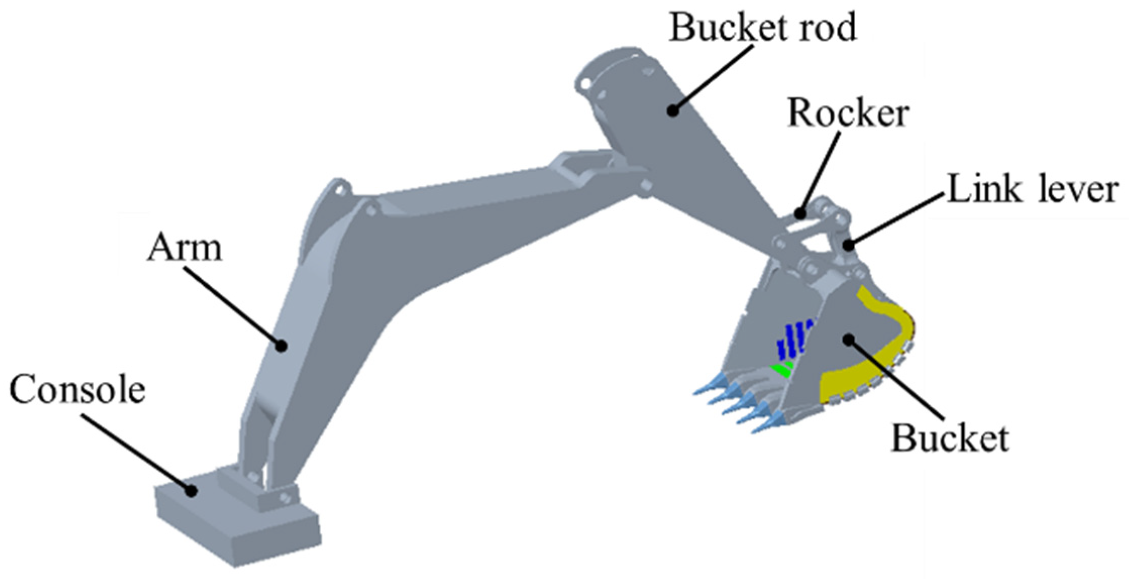
An excavator is the key equipment in mining operations, and the bucket is the core component of an excavator. During the excavation operation, the bucket needs to overcome the excavation resistance formed by its interaction with the material. In addition, the resistance determines the energy consumption during excavator operation. The excavation resistance generally includes the cutting resistance of the material to the bucket teeth and cutting edge, the frictional resistance when the material flows along the bucket bottom plate and side walls and the force generated by overcoming the internal friction of the material. This resistance value varies with the state of the material (texture, moisture content), particle size distribution, thickness of the cutting layer and structural dimensions of the bucket [1,2,3]. At present, there are some problems with excavators such as high excavation resistance, high energy consumption and low filling rate, which greatly limit the working efficiency and service life of excavators. The structural parameters of the bucket can directly affect the excavation resistance and energy consumption of the bucket, so it is necessary to optimize the structural parameters of the bucket, which can reduce the excavation energy consumption and extend the service life of the bucket to a certain extent.
The geological conditions of our country are complicated and diverse, and the kinds of ores are abundant. The ore properties (Poisson ratio, density, shear modulus) in different regions are quite different, which leads to a great difference in the contact properties (collision coefficient of restitution, coefficient of static friction, coefficient of rolling friction) between the bucket and the ore. The excavation performance (excavation resistance, energy consumption and filling rate) of the bucket varies when excavating different ores. The resistance value changes with the state of the material (texture, water content), particle size distribution, bucket structure and size. The cutting resistances of the cutting edge and the bucket teeth are related to the mechanical characteristics of the material, and the friction resistance is related to the internal friction angle of the material, the firmness of the material, the parameters of the bucket teeth and the cutting edge, the cutting edge angle and other factors. Therefore, it is of great significance to optimize the structural parameters of the bucket to improve the excavation performance and service life of the bucket for different excavation conditions.
In recent years, with the development of computer assistive technology, more and more experts and scholars use numerical simulation methods such as finite element method and discrete element method to predict the excavation resistance and optimize the bucket structure. The finite element method (FEM) is a numerical technique for solving approximate solutions to boundary value problems of partial differential equations. When solving the problem, the whole problem region is decomposed, and each subregion becomes a simple part called a finite element. The discrete element method (DEM) is a numerical calculation method mainly used to calculate how a large number of particles move under given conditions. Paul [4] and Malone [5] applied the discrete element method to the field of engineering machinery to explore the contact relationship between the excavator bucket and the materials. Nezami et al. [6] established polyhedral soil particle models and used the discrete element method to explore the interaction between the bucket and the soil. Shmulevich [7,8] used the discrete element method to simulate the process of cutting soil with the bucket and analyzed the relationship between blade shape and cutting performance, confirming the superiority of the discrete element method in analyzing the mechanical relationship between soil and bucket. Asaf et al. [9] analyzed the dynamic interaction between soil and bucket during soil cutting. In order to more accurately utilize EDEM for simulation analysis, parameter measurement experiments were designed. Mootaz et al. [10] used the finite element method to analyze the interaction between the bucket and the material and considered the dynamic influence of the material. Coetzee et al. [11,12,13] established a discrete element model of the excavator operation process and predicted the impact of different model parameters on the bucket excavation resistance and filling rate by changing the bucket geometric modeling. Gan et al. [14] used the discrete element method to study and analyze the loading condition of the bucket during the working process of the mining hydraulic excavator, providing a basis for the shape optimization of the bucket.
At present, numerical simulation methods are widely used in the simulation of excavation processes. However, the modeling of ore is relatively simple, such as all ore particles being circular. In actual excavation, ore models are complex and diverse [15,16,17]. In order to simulate the actual excavation process under different geological conditions, the shape and size of the ore models should be as close as possible to the shape and size of actual ores. In addition, the ore parameters in different geological environments are very different, so these parameters should not only rely on the literature, but also be obtained in combination with specific tests. The modeling and parameter settings of ore have a great influence on the simulation results. Therefore, the simplified ore model and the parameters obtained by referring to the previous literature have a great influence on the simulation results.
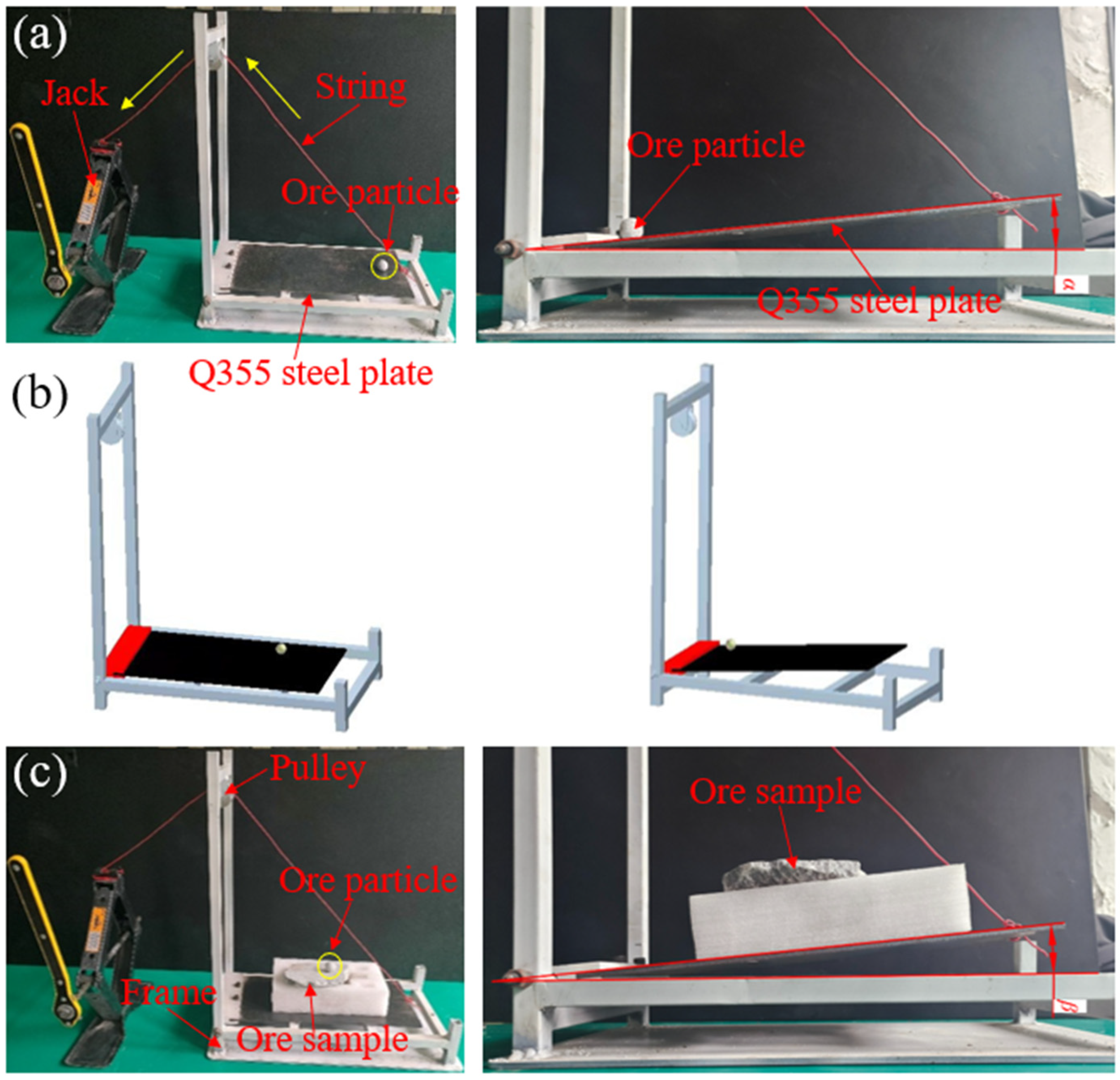
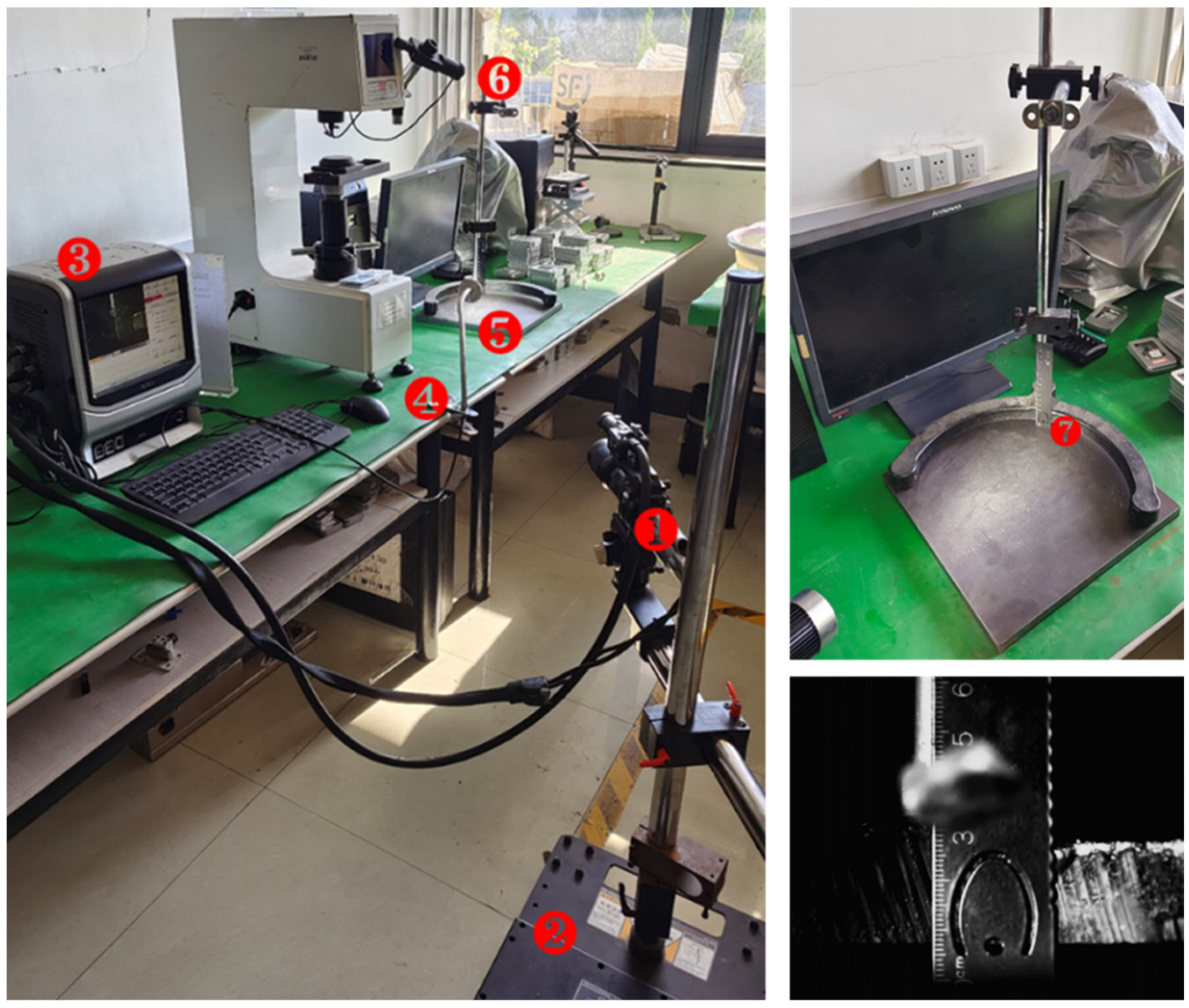
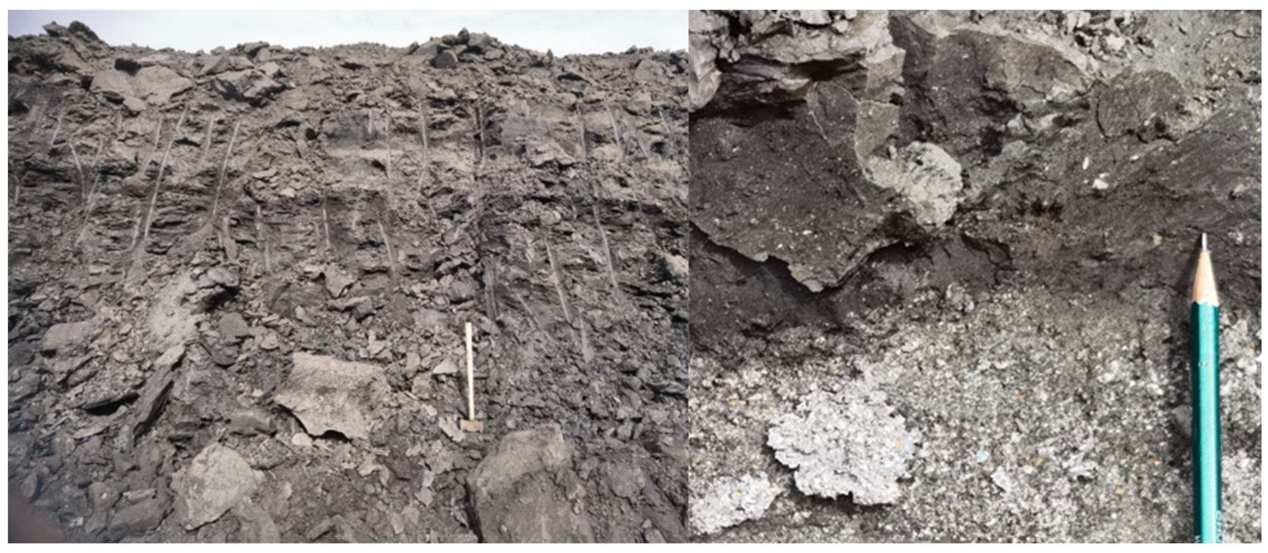
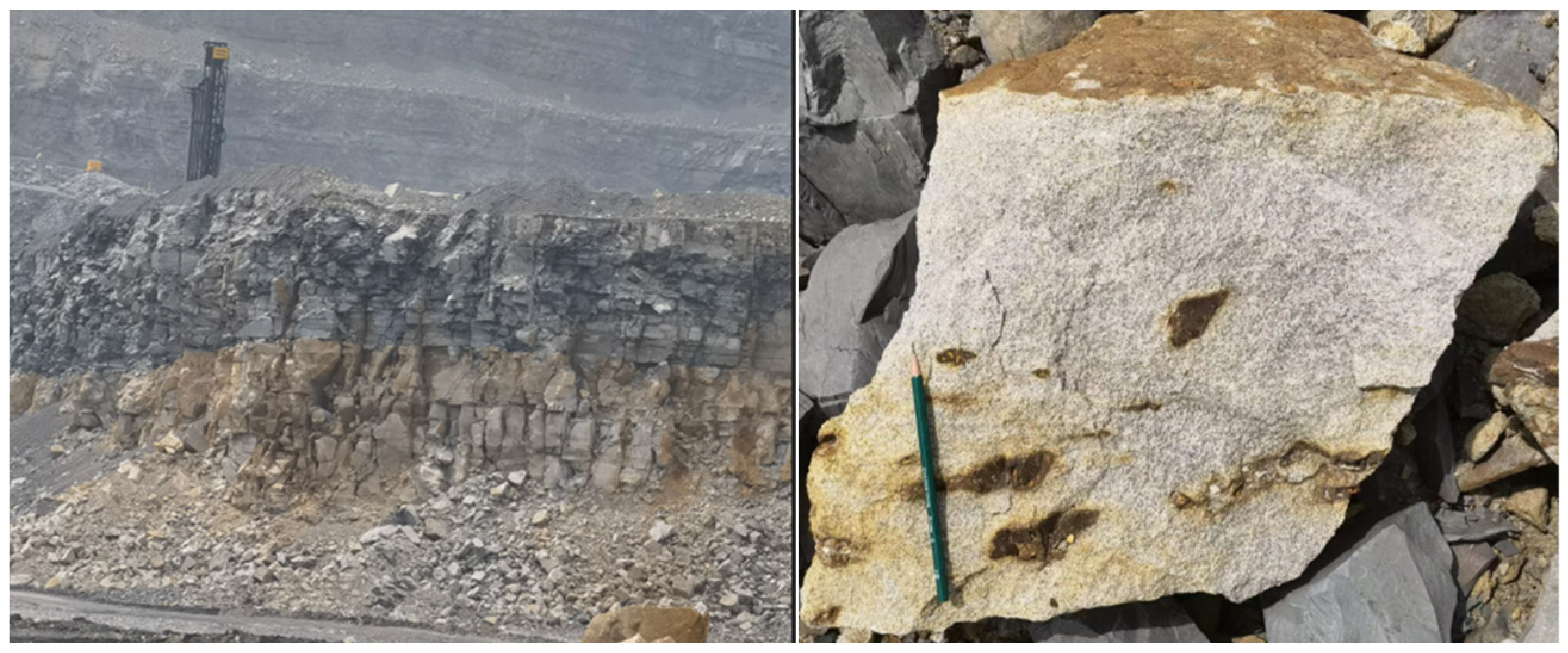
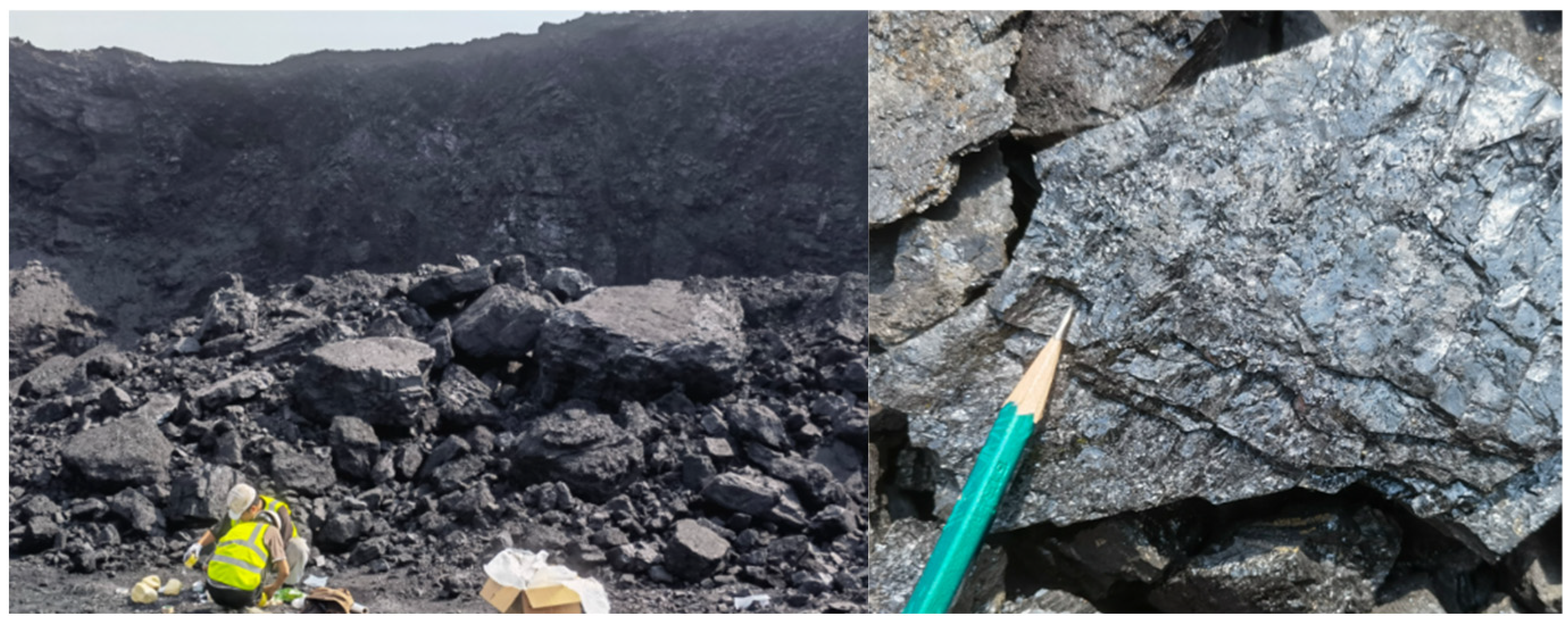
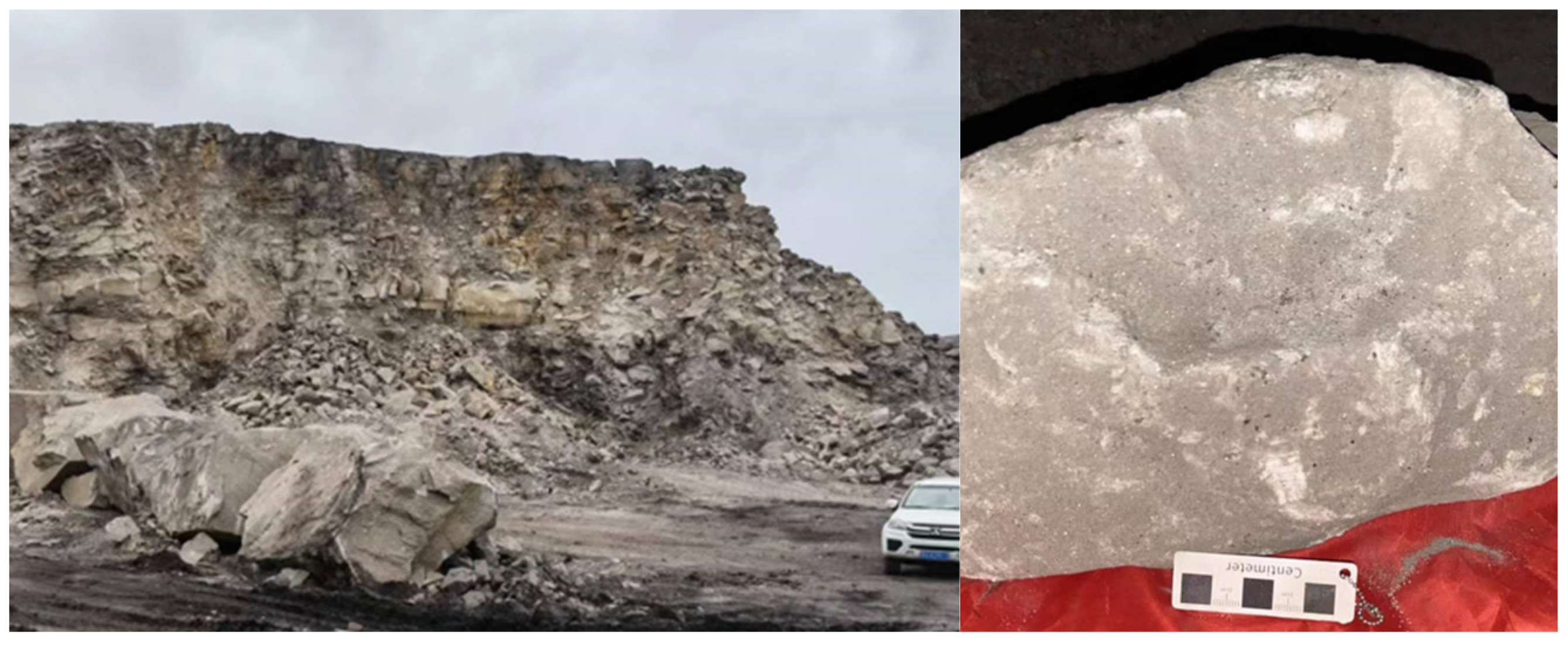
In order to explore the optimization methods for structural parameters of buckets under different excavation conditions, geological surveys were conducted on some types of ores in Inner Mongolia and Shanxi to obtain the shape characteristics, size distribution, and material properties of different kinds of ores, and the size distribution and mass proportion of different ore particles were set in EDEM. In addition, the static friction coefficient test device, the rolling friction coefficient test device and the collision coefficient of restitution test device were set up to accurately measure the contact parameters between the bucket and the ore and between the ore and the ore.
In this study, an Adams-EDEM coupled simulation method was used to study the influence of bucket structure parameters on the excavation performance (excavation resistance, energy consumption, filling rate) of excavators under different geological conditions. Additionally, the orthogonal experimental method was used to obtain the optimal parameters combinations of bucket structure, achieving optimization of the excavator bucket structure for different geological conditions.

2. Adams-EDEM Coupled Simulation Method

2.1. Determination of Contact Parameters

In order to explore structural optimization methods for buckets under different geological conditions, four typical ore types in China were selected, namely Mengdong mudstone, Shanxi gritstone, Shanxi coal rock and Wuhai mudstone.
To simulate the process of excavating ore with the excavator in EDEM, it is necessary to set the contact parameters between ore and bucket, as well as between ore and ore. The material of the bucket is mainly Q355 steel. In order to accurately measure the contact parameters between the bucket and the ore and between the ore and the ore, the static friction coefficient test device, the rolling friction coefficient test device and the collision coefficient of restitution test device were set up.

2.1.1. Test Method for Static Friction Coefficient

The static friction coefficient test device was designed based on the calculation method of the static friction coefficient, μ = F/N (where F is the magnitude of the static friction force, μ is the coefficient of static friction and N is the pressure between the objects).
The static friction coefficient test device is shown in Figure 1, and the steps of the testing method are as follows: (1) Place the ore block on the Q355 steel plate and wrap the string around the pulley to connect one end to the ore block and the other end to the load-bearing cup. (2) Adjust the height of the pulley so that the string is parallel to the Q355 steel plate. (3) Slowly add water to the load-bearing cup using a dropper until the ore block begins to slide and stop adding water. At this point, the weight of the load-bearing cup and the water in the cup (m2) is the force required to overcome the static friction force (F) between the ore sample and the steel plate. The weight of the ore sample (m1) is the contact pressure between the ore sample and the steel plate. (4) Measure the mass of the ore block (m1) and the mass of the load-bearing cup containing water (m2) using an electronic balance, and calculate the static friction coefficient via μ = m2/m1. (5) Repeat this test 10 times and take the average of the static friction coefficient calculated from the 10 tests as the static friction coefficient between the ore and bucket.
Using the same test method, replace the contact pair from the steel plate to the ore sample, as shown in Figure 1b. Repeat the above test process to obtain the static friction coefficient between the ore and the ore.

2.1.2. Test Method for Rolling Friction Coefficient

The rolling friction coefficient between the ore sample and the steel plate cannot be directly obtained from experiments. The design of the rolling friction coefficient testing device is to obtain the angle between the steel plate and the horizontal plane when the ore sample starts to roll.
The rolling friction coefficient test device is shown in Figure 2, and the steps of the testing method are as follows: (1) Place the ore particle on the Q355 steel plate, with one end of the string connected to the Q355 steel plate and the other end connected to the jack after passing through the fixed pulley. (2) By adjusting the height of the jack with a wrench, the string slowly lifts one end of the Q355 steel plate, gradually increasing the inclination angle between the steel plate and the horizontal plane. When the inclination angle increases to a certain value, the ore particle will roll. (3) Use a high-speed camera to capture the entire process of ore particle rolling, and obtain the picture of the moment when the ore particle begins to roll. Measure and record the angle between the steel plate and the horizontal plane at this time. Considering the test error, repeat this test 10 times and take the average of the 10 test results as the angle between the steel plate and the horizontal plane at the beginning of the ore particle rolling. (4) The acquisition of the rolling friction coefficient requires the combination of experiment and simulation. Therefore, use a 3D scanner to scan the ore particle, establish the 3D model of the ore particle, and import the model of the ore particle and the rolling friction coefficient test device into the EDEM software to simulate the real rolling friction coefficient test process in the EDEM. (5) In the EDEM contact parameter setting panel, set different rolling friction coefficients for simulation experiments. Simulate the real test and slowly increase the inclination angle of the Q355 steel plate and record the angle when the ore particle begins to roll. When the inclination angle obtained via simulation is the same as the inclination angle obtained via experiment, the rolling friction coefficient set in EDEM is the actual rolling friction coefficient between ore particle and steel plate.
Using the same test method, replace the contact pair from steel plate to ore sample, as shown in Figure 2c. Repeat the above test process to obtain the rolling friction coefficient between the ore and the ore.

2.1.3. Test Method for Collision Recovery Coefficient

The test device of collision coefficient of restitution is designed based on the calculation method of collision coefficient of restitution, C r = v f v i = h H (where H is the height before the object falls and h is the height of the object rebounds).
The collision coefficient of restitution test device is shown in Figure 3, and the steps of the testing method are as follows: (1) Adjust the height, shooting angle, aperture focal length, light source position, etc., of the high-speed camera to ensure that the shooting area can be clearly presented. (2) Fix the scale and select a certain height H to allow the ore particle to freely fall onto the Q355 steel plate below. Use a high-speed camera to capture the entire process of ore particle falling and rebounding, and repeat this process 10 times. (3) Based on the video captured using the high-speed camera, capture the image of the ore particle rebounding to its maximum height. The rebound height h is read according to the scale, and the average value of 10 measurements is taken as the maximum rebound height of the ore particle. The ratio of rebound height h and falling height H is the collision recovery coefficient, in which the height H is 500 mm.
Similarly, replace the steel plate with ore samples, and repeat the above test process to obtain the collision coefficient of restitution between the ore and the ore.
Finally, the static friction coefficient, rolling friction coefficient and collision coefficient of restitution between bucket material and ore and between ore and ore were obtained through testing, as shown in Table 1.

2.2. Establishment of Adams-EDEM Coupled Simulation Model

An Adams-EDEM co-simulation method was used to simulate the actual excavation process of excavators to explore the excavation performance of buckets with different structures under different geological conditions. The co-simulation process mainly includes the construction of an excavator model, constraints and drive settings for the model, construction of different particle models, construction of Adams-EDEM coupled simulation model and simulation calculation.

2.2.1. Construction of Excavator Model

In this study, an XB120R700 hydraulic excavator was used as the original model, and the excavator model was reconstructed in a 1:1 ratio using Pro/E. In order to reduce simulation computation and improve computational efficiency, the excavator model was appropriately simplified by removing components such as oil cylinders that do not affect the structural analysis of the bucket. The simplified model is shown in Figure 4.

2.2.2. Constraints and Drive Settings for the Model

The simplified excavator model was imported into Adams, and the various components of the excavator were constrained. Table 2 shows the setting of the excavator constraints. For example, in the excavation process, the console is fixed, so the fixed pair is set between the console and the ground. The arm rotates around the console, so the rotation pair is set between the arm and the console. Table 3 shows the setting of the excavator driving function. The drive of the excavator was set according to the STEP function in Adams. Finally, the excavation trajectory of the bucket was obtained, as shown in Figure 5.

2.2.3. Construction of Different Ore Particle Models

In order to simulate the actual excavation process, the particle size distribution and mass proportion of Mengdong mudstone, Shanxi gritstone, Shanxi coal rock and Wuhai mudstone were determined through a geological survey and the particle models of typical ores were obtained using a 3D scanner.
Mengdong mudstone is a gray-black thick block or layered silty mudstone that is partially mixed with light gray lenticular argillaceous fine-coarse sandstone. The sandstone is loose, the silt content in the mudstone is low, and the fine sandstone is the main component. The geological conditions of Mengdong mudstone is shown in Figure 6.
Shanxi gritstone is originally grayish-white, but after weathering, it is earthy yellow. It is a medium-thick to super-thick layered gritstone mixed with dark gray thin layer silty mudstone, which reflects the characteristics of braided river sedimentation. The geological conditions of Shanxi gritstone is shown in Figure 7.
Shanxi coal, produced horizontally, is black giant thick stratified bright coal with a primary banded structure, as shown in Figure 8.
Wuhai mudstone is a dark gray medium-thick to thick layered silty mudstone, rich in plant leaf and stem fossils, and the individual fossils are relatively large and the structure is relatively complete. The geological conditions of Wuhai mudstone is shown in Figure 9.
The 3D models of different ore particles were obtained using a 3D scanner. Finally, the models were imported into the discrete element software EDEM.
The particle size distribution and particle models of typical ores are shown in Table 4. The material properties of the bucket and ores are shown in Table 5.

2.2.4. Construction of Adams-EDEM Coupled Simulation Model

The excavator model was imported into EDEM, and the bucket was merged into one component. The coupled simulation files were loaded in Adams Co-simulation to realize Adams-EDEM coupled simulation, as shown in Figure 10. To ensure the accurate operation of coupled simulation, it was necessary to maintain the consistency of the pose, name and centroid coordinates of the components in EDEM with those in Adams.

2.3. Orthogonal Experimental Design

Orthogonal experimental design refers to a kind of efficient and economical experimental design method that studies the experiment results influenced by multi-factors and multi-levels. Some representative points are selected from the comprehensive experiment based on orthogonality for testing, and these representative points have the characteristics of uniform dispersion, neatness and comparability.
In this study, the structure of the bucket was optimized to reduce the excavation resistance and energy consumption of the bucket and improve the filling rate of the bucket. The four main structural parameters of the bucket were selected as experiment factors, which are edge angle (θ), flare angle (β), bucket width (D) and arc radius of bucket bottom (R), and the structure of the bucket is shown in Figure 11. Three levels were selected for each experimental factor. If a comprehensive experiment were conducted, 81 experiments would be required. Therefore, the comprehensive experiment would take a long time and require a large amount of work. The L9(34) orthogonal table (Table 6) was used to arrange the experiment, and the excavation performance of buckets with different structure was compared.

3. Results and Discussion

The excavation performance of an excavator usually includes excavation resistance, excavation energy consumption and filling rate of the bucket. Based on the orthogonal experiment table, the influence of bucket structure on excavation performance was investigated under different geological conditions.

3.1. Excavation Resistance

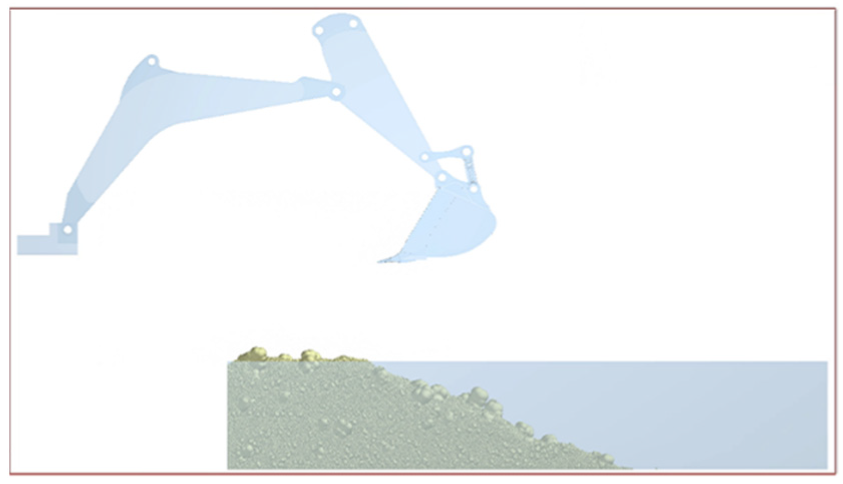
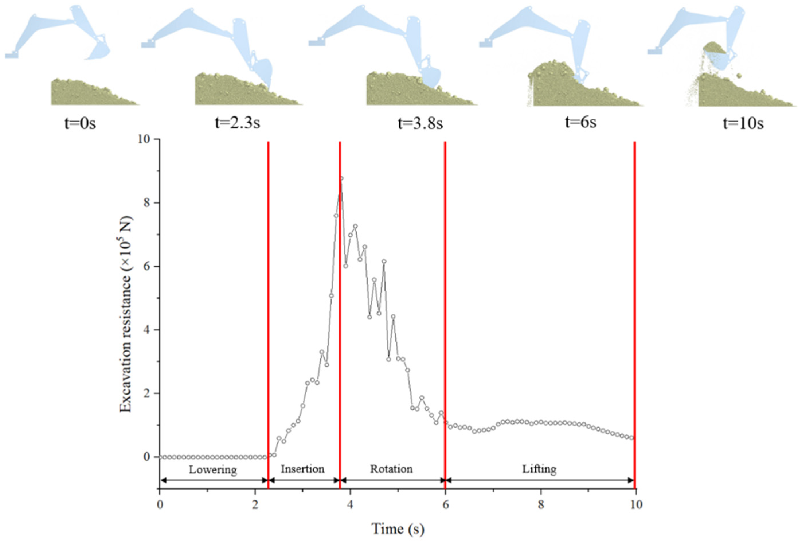
In order to explore the trend in excavation resistance of the bucket during the excavation process, the excavation resistance of the original bucket model during the process of excavating Shanxi coal was obtained via EDEM. The trend of the overall excavation resistance of the bucket during the excavation process is shown in Figure 12. The entire excavation process can be divided into four stages. Within 0 s to 2 s, the arm is lowered and the bucket is not in contact with the ore material, so the value of excavation resistance is zero. Within 2 s to 4 s, the bucket begins to come into contact with the ore material and needs to overcome the adhesion between ore particles. As the depth of the bucket inserted into the ore material pile increases, the excavation resistance also increases. Until most of the space in the bucket is filled with ore material, the excavation resistance begins to decrease. Within 4 s to 6 s, the bucket rod stops moving and the bucket rotates around the bucket rod. The ore material has a high fluidity in the bucket, which can cause a certain impact on the bucket, resulting in significant fluctuations in excavation resistance. However, overall, the excavation resistance of the ore material to the bucket gradually decreases. Within 6 s to 10 s, the arm is lifted and the bucket is filled with the ore material. At the beginning, due to the simultaneous movement of the arm and the bucket, the excavation resistance of the bucket fluctuates. Subsequently, the bucket begins to detach from the ore material pile, and the contact between the bucket and the ore material pile gradually decreases, resulting in a continuous decrease in excavation resistance. After the bucket completely detaches from the ore material pile, the force on the bucket is the gravity of the ore material in the bucket. A small amount of ore material falls from the bucket, resulting in a slight decrease in excavation resistance, but the overall trend of change is stable.
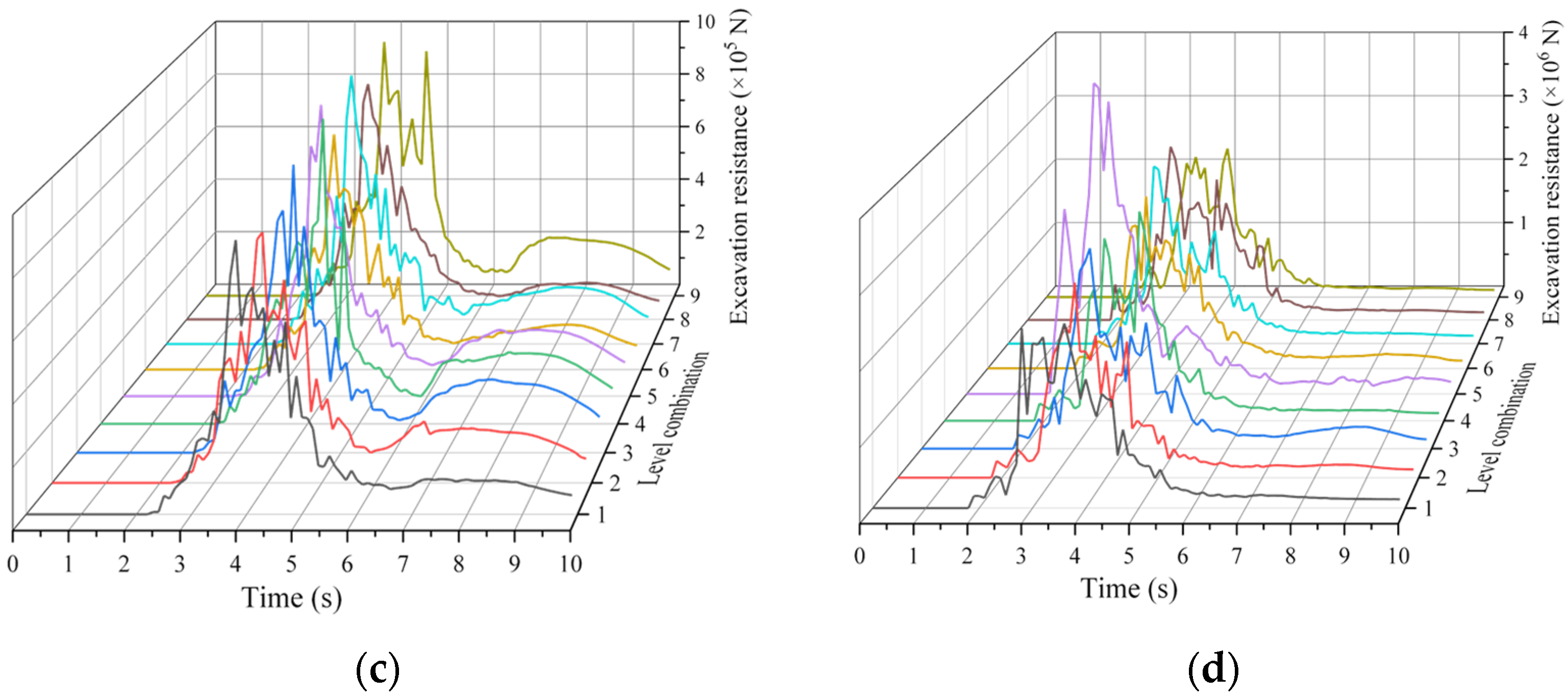
Figure 13 shows the comparison of excavation resistance when the structural parameters of the bucket are different level combinations. Under different geological conditions, the variation trends of excavation resistance of buckets with time are roughly similar and can be divided into four stages. During the lifting stage of the bucket, except for Shanxi coal, the excavation resistance of the bucket is relatively stable and does not fluctuate significantly under the other three geological conditions. Mainly due to the large gap between the coal particles in Shanxi coal, there are phenomena such as ore material flow and collapse during the lifting of the bucket, which causes a certain impact on the bottom plate and lateral plates of the bucket, resulting in the excavation resistance of the bucket showing a trend of first increasing and then decreasing. In addition, the parameter combinations of the bucket structure corresponding to the minimum excavation resistance of the bucket under different geological conditions are different. When excavating Mengdong mudstone, Shanxi gritstone, Shanxi coal and Wuhai mudstone, the parameter combinations of the bucket structure corresponding to the minimum excavation resistance are combination 7, combination 1, combination 6 and combination 9.

3.2. Filling Rate and Energy Consumption

The calculation formula for the filling rate of the bucket is:
μ = V 1 V
where η is the filling rate, V1 is the actual volume of material loaded by the bucket and V is the capacity of the bucket.
The calculation formula for energy consumption of excavating per unit mass of material by the bucket is:
E = t 1 t 2 F p ( t ) · v p d t + t 1 t 2 F l ( t ) · v l d t
where E is the energy consumption, t is the excavation time, Fp is the horizontal excavation resistance of the material to the bucket during the excavation process, Fl is the vertical excavation resistance of the material to the bucket during the excavation process, vp is the horizontal speed of the bucket during excavation process and vl is the vertical speed of the bucket during excavation process.
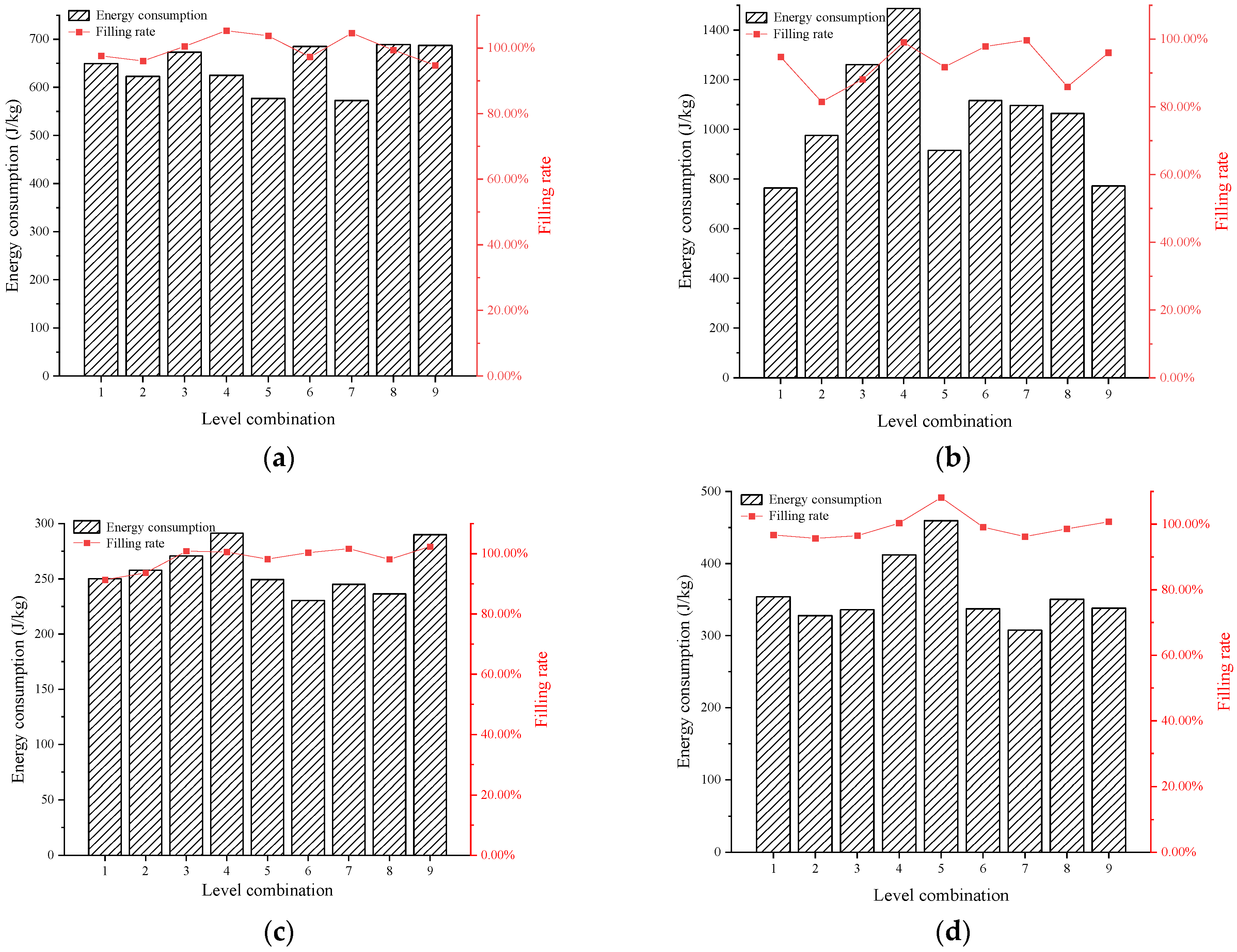
Figure 14 shows the comparison of energy consumption of excavating per unit mass of ore material by the bucket and filling rate when the structural parameters of the bucket are different level combinations. Combined with the excavation resistance of the bucket under different structural parameter combinations, the parameter combinations of bucket structure corresponding to the optimal excavation performance (low excavation resistance and energy consumption, high filling rate) under different geological conditions were selected. When excavating Mengdong mudstone, Shanxi gritstone, Shanxi coal and Wuhai mudstone, the parameter combinations of the bucket structure corresponding to the optimal excavation performance were combination 7, combination 1, combination 6 and combination 9. The optimal parameter combinations of the bucket structure under different geological conditions were obtained by comprehensively considering the excavation performance of the bucket (including excavation resistance, energy consumption and filling rate), as shown in Table 7.

3.3. Excavation Resistance of the Main Components of the Bucket

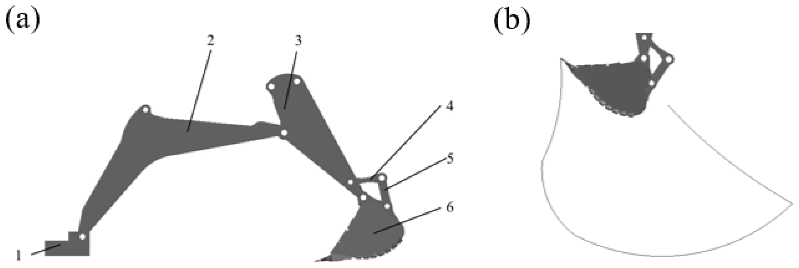
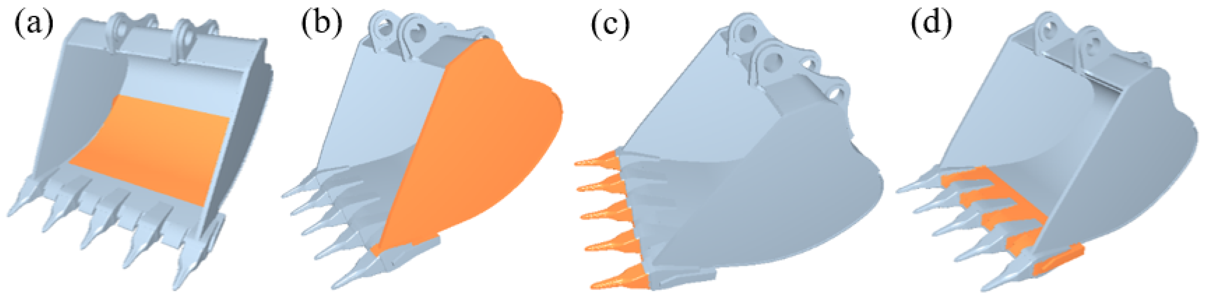
To compare the excavation resistance before and after optimizing the structure of the bucket, the main load-bearing components of the bucket (Figure 15), including the bottom plate, lateral plate, bucket teeth and blade plate, were selected for comparative analysis of excavation resistance.
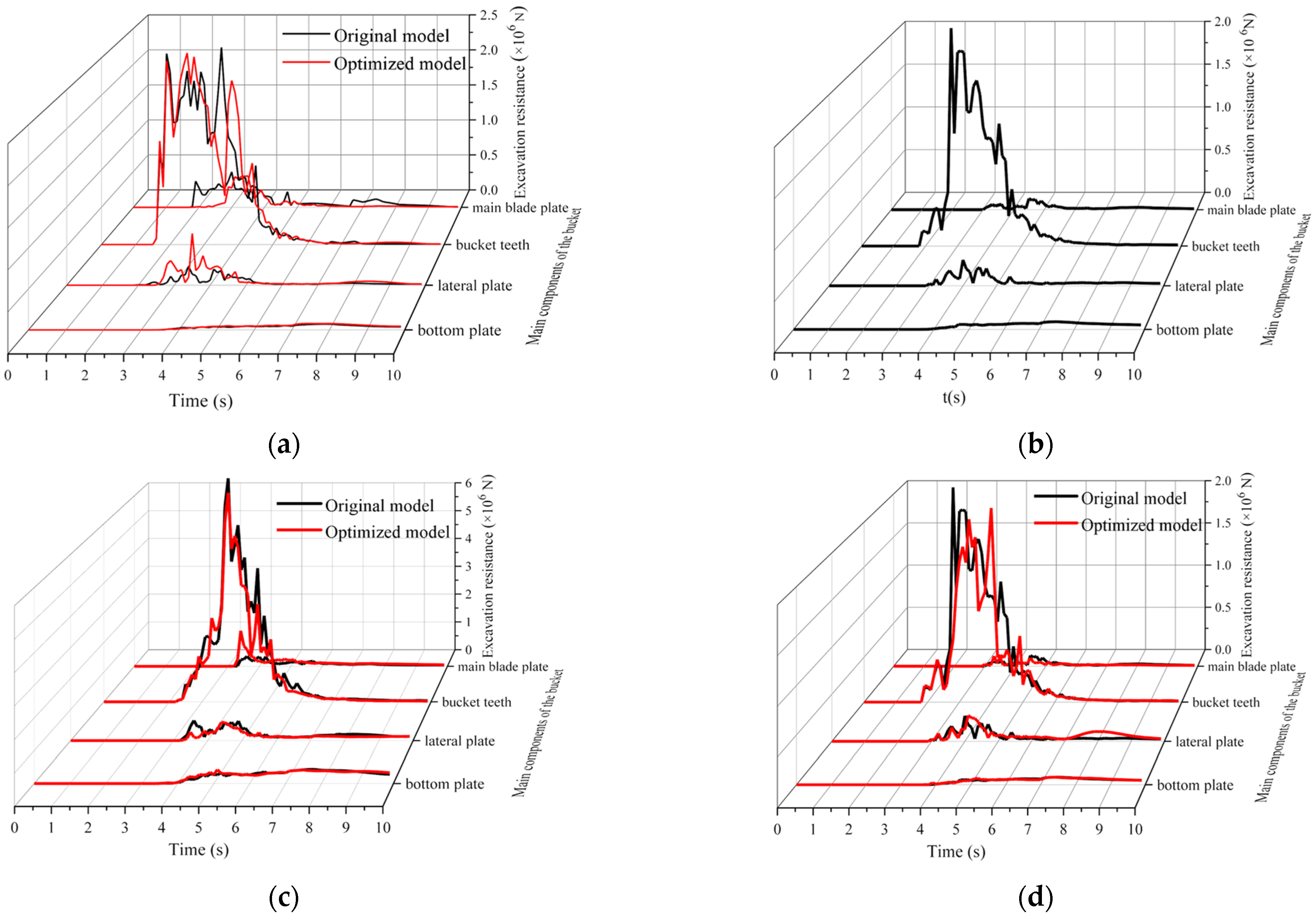
Figure 16 shows the comparison of the excavation resistance of the main load-bearing components before and after the optimization of the bucket structure under different geological conditions. Among them, the optimal bucket model for mining Shanxi coal is the original model of the bucket. During the excavation process, the bucket teeth first come into contact with the ore material. As the main load-bearing component, the bucket teeth are subjected to the greatest excavation resistance. As the excavation progresses, the blade plate and lateral plates of the bucket come into contact with the ore material. The bucket teeth are installed on the blade plate, and the excavation resistance suffered by the bucket teeth is transmitted to the blade plate. In addition, during the excavation process, the blade plate and lateral plates have the function of assisting in excavating ore materials, so the blade plate and lateral plates are also subjected to significant excavation resistance. However, the excavation resistance of the blade plate and lateral plates is much smaller than that of the bucket teeth. During the excavation process, there are random fluctuations in the excavation resistance of the bucket teeth, blade plate, and lateral plates, mainly due to the inconsistent particle size of the ore material and the fluidity of the ore material. With the filling of the ore materials in the bucket, the excavation resistance of the bottom plate gradually increases. In addition, because the bottom plate only bears the mass of the ore material, the excavation resistance is low and there is no significant fluctuation.
Comparing the excavation resistance of the main load-bearing components before and after the optimization of the bucket structure, it was found that the excavation resistance of the bucket teeth is the highest under different geological conditions. After optimizing the bucket structure, the maximum excavation resistance of the bucket teeth was significantly reduced. Due to the small excavation resistance of the main blade plate, lateral plates and bottom plate of the bucket, the changes in excavation resistance before and after optimization were not significant. The bucket teeth are the most important load-bearing components, and the excavation resistance of the bucket teeth is the highest during the excavation process. Therefore, the bucket teeth are the most easily damaged parts, which affects the work efficiency of the excavator. In addition, the reduction in excavation resistance of the main components of the bucket is beneficial for reduction in stress and deformation during the bucket excavation process, thereby reducing the probability of damage to the bucket and extending its service life.
After structural optimization, the overall excavation resistance and maximum excavation resistance of the bucket are reduced, which can effectively improve the service life of the bucket.

4. Conclusions

In this study, the bucket structure was optimized for different geological conditions based on the orthogonal experimental method and the Adams-EDEM coupled method. The main conclusions are as follows:
Based on the excavation resistance characteristics of the bucket, the excavation process can be divided into four stages: (1) The bucket is lowered without touching the ore material. (2) The bucket continuously inserts ore material. (3) The bucket rotates around the bucket rod to fill with ore material. (4) The bucket is lifted when the bucket is filled with ore material.
According to the orthogonal experimental method, the optimized parameter combinations of bucket structures under different geological conditions were obtained, and it was found that the optimized structure of the bucket is different under different geological conditions. Therefore, it is necessary to optimize the bucket structure for different geological conditions.
Comparing the excavation resistance changes of the main load-bearing components before and after bucket optimization, it was found that the bucket teeth are the main load-bearing components during the excavation process. After structural optimization, the excavation resistance of the bucket teeth is significantly reduced, while the excavation resistance changes of other components of the bucket are relatively small.
In this study, the stress and deformation analysis of the bucket before and after the structural optimization was not carried out to analyze the damaged position of the bucket so as to further optimize the bucket structure. In future research, dynamic, discrete element and finite element methods can be combined to carry out static analysis of the bucket before and after structural optimization. By comparing the stress and deformation of the bucket before and after structure optimization, the structure of the bucket is further improved. In addition, the optimized bucket can be manufactured according to the reduction ratio, sensor technology can be used to monitor the excavation resistance during the excavation process, and the mining energy consumption and filling rate can be calculated to verify the simulation results.

Author Contributions

Conceptualization, Y.W., L.W. and D.W.; methodology, Y.W., L.W., C.L., Z.X. and Y.S. (Yuan Sun); software, Z.X., Y.S. (Yuan Sun), X.W., L.T., Y.S. (Yuewei Sun) and W.X.; formal analysis, Y.W., C.L., Z.X. and Y.S. (Yuan Sun); investigation, Y.W., L.W., C.L., Z.X., Y.S. (Yuan Sun), R.M., D.W., M.C., X.W., L.T., Y.S. (Yuewei Sun) and W.X.; data curation, Z.X., Y.S. (Yuan Sun), R.M., M.C., X.W., L.T., Y.S. (Yuewei Sun) and W.X.; writing—original draft preparation, Y.W. and C.L.; writing—review and editing, L.W. and D.W.; supervision, Y.W., R.M., D.W. and M.C.; project administration, D.W.; funding acquisition, D.W. All authors have read and agreed to the published version of the manuscript.

Funding

This research was funded by the project from CUMT-XCMG Mining Intelligent Equipment Technology Research Institute (Grant no. 2020050049 2202).

Informed Consent Statement

Not applicable.

Data Availability Statement

Data will be made available on request.

Conflicts of Interest

We declare that we have no financial and personal relationships with other people or organizations that can inappropriately influence our work and that there are no professional or other personal interests of any nature or kind in any product, service and/or company that could be construed as influencing the position presented in, or the review of, this manuscript.

References

  1. Velikanov, V.S.; Kozyr, A.V.; Dyorina, N.V. Engineering Implementation of View Objectives in Mine Excavator Design. Procedia Eng. 2017, 206, 1592–1596. [Google Scholar] [CrossRef]
  2. Liu, B.W.; Zhou, Z.Y.; Gan, J.Q.; Ellis, D.; Zou, R.P.; Yu, A.B. Investigation of performance of hydraulic excavators by co-simulation of multibody dynamics and discrete element method. Powder Technol. 2023, 414, 118088. [Google Scholar] [CrossRef]
  3. Jiang, Y.Z.; Liao, G.W.; Zhu, S.S.; Hu, Y.F. Investigation on cutting resistance characteristic of bucket wheel excavator using DEM and DOE methods. Simul. Model. Pract. Theory 2021, 111, 102339. [Google Scholar] [CrossRef]
  4. Paul, W.C. DEM simulation of industrial particle flows: Case studies of dragline excavators, mixing in tumblers and centrifugal mills. Powder Technol. 2000, 109, 83–104. [Google Scholar] [CrossRef]
  5. Malone, K.F.; Xu, B.H. Determination of contact parameters for discrete element method simulations of granular systems. Particuology 2008, 6, 521–528. [Google Scholar] [CrossRef]
  6. Nezami, E.G.; Hashash, A.Y.M.; Zhao, D.W.; Ghaboussi, J. Simulation of front end loader bucket-soil interaction using discrete element method. Int. J. Numer. Anal. Met. 2007, 31, 1147–1162. [Google Scholar] [CrossRef]
  7. Shmulevich, I.; Asaf, Z.; Rubinstein, D. Interaction between soil and a wide cutting blade using the discrete element method. Soil Tillage Res. 2007, 97, 37–50. [Google Scholar] [CrossRef]
  8. Shmulevich, I. State of the art modeling of soil-tillage interaction using discrete element method. Soil Tillage Res. 2010, 111, 41–53. [Google Scholar] [CrossRef]
  9. Asaf, Z.; Rubinstein, D.; Shmulevich, I. Determination of discrete element model parameters required for soil tillage. Soil Tillage Res. 2007, 92, 227–242. [Google Scholar] [CrossRef]
  10. Mootaz, A.E.; Hamilton, R.; Boyle, J.T. 3D Dynamic analysis of soil-tool interaction using the finite element method. J. Terramech. 2003, 40, 51–62. [Google Scholar] [CrossRef]
  11. Coetzee, C.J.; Els, J.D.N. The numerical modelling of excavator bucket filling using DEM. J. Terramech. 2009, 46, 217–227. [Google Scholar] [CrossRef]
  12. Coetzee, C.J.; Basson, A.H.; Vermeer, P.A. Discrete and continuum modelling of excavator bucket filling. J. Terramech. 2007, 44, 177–186. [Google Scholar] [CrossRef]
  13. Coetzee, C.J.; Els, J.D.N. Calibration of discrete element parameters and the modelling of silo discharge and bucket filling. Comput. Electron. Agric. 2009, 65, 198–212. [Google Scholar] [CrossRef]
  14. Gan, J.Q.; Zhou, Z.Y.; Yu, A.B.; Ellis, D.; Attwood, R.; Chen, W. Co-simulation of multibody dynamics and discrete element method for hydraulic excavators. Powder Technol. 2023, 414, 118001. [Google Scholar] [CrossRef]
  15. Wicek, J.; Stasiak, M.; Kafashan, J. Structural and micromechanical properties of ternary granular packings: Effect of particle size ratio and number fraction of particle size classes. Materials 2020, 13, 339. [Google Scholar] [CrossRef] [PubMed]
  16. Kafashan, J.; Wiacek, J.; Ramon, H.; Mouazen, A.M. Modelling and simulation of fruit drop tests by discrete element method. Biosyst. Eng. 2021, 212, 228–240. [Google Scholar] [CrossRef]
  17. Chen, D.; Kang, G.; Yang, J.; Zhang, L. Functionally graded porous structures: Analyses, performances, and applications—A Review. Thin-Walled Struct. 2023, 191, 111046. [Google Scholar] [CrossRef]
Figure 1. Test device of static friction coefficient: (a) test device of static friction coefficient between the ore and bucket material, (b) test device of static friction coefficient between the ore and ore.
Applsci 13 11336 g001
Figure 2. Test device of rolling friction coefficient: (a) test device of rolling friction coefficient between the ore and bucket material, (b) simulation of the real rolling friction coefficient test process in the EDEM, (c) test device of rolling friction coefficient between the ore and ore.
Applsci 13 11336 g002
Figure 3. Test device of collision coefficient of restitution. 1—high-speed camera (VW-Z2); 2—camera mount; 3—ultra depth of field 3D microscope (VW-9000); 4—illuminant; 5—Q355 steel plate; 6—ore collision test bench; 7—scale.
Applsci 13 11336 g003
Figure 4. Simplified model of XB120R700 hydraulic excavator.
Applsci 13 11336 g004
Figure 5. Excavator dynamics model: (a) excavator simulation model, (b) bucket tooth excavation trajectory. 1—console; 2—arm; 3—bucket rod; 4—rocker; 5—link lever; 6—bucket.
Applsci 13 11336 g005
Figure 6. Geological conditions of Mengdong mudstone.
Applsci 13 11336 g006
Figure 7. Geological conditions of Shanxi gritstone.
Applsci 13 11336 g007
Figure 8. Geological conditions of Shanxi coal.
Applsci 13 11336 g008
Figure 9. Geological conditions of Wuhai mudstone.
Applsci 13 11336 g009
Figure 10. Adams-EDEM coupled simulation model.
Applsci 13 11336 g010
Figure 11. Schematic diagram of bucket structure: (a) schematic diagram of edge angle and arc radius of bucket bottom, (b) schematic diagram of bucket width and flare angle.
Applsci 13 11336 g011
Figure 12. Trend of changes in excavation resistance of the bucket.
Applsci 13 11336 g012
Figure 13. Variation trends in excavation resistance of buckets with different structures under different geological conditions: (a) Mengdong mudstone, (b) Shanxi gritstone, (c) Shanxi coal, (d) Wuhai mudstone (Note: Different colors correspond to different parameter combinations, and 1–9 indicates 9 structural parameter combinations).
Applsci 13 11336 g013aApplsci 13 11336 g013b
Figure 14. Variation trends of energy consumption of excavating per unit mass of ore material and filling rate of buckets with different structures under different geological conditions: (a) Mengdong mudstone, (b) Shanxi gritstone, (c) Shanxi coal, (d) Wuhai mudstone.
Applsci 13 11336 g014
Figure 15. Main load-bearing components of the bucket: (a) bottom plate, (b) lateral plate, (c) bucket teeth, (d) blade plate.
Applsci 13 11336 g015
Figure 16. Comparison of the excavation resistance of the main load-bearing components before and after the optimization of the bucket structure under different geological conditions: (a) Mengdong mudstone, (b) Shanxi gritstone, (c) Shanxi coal, (d) Wuhai mudstone.
Applsci 13 11336 g016
Table 1. Contact parameters between bucket and ores and between ores and ores.
Ore TypeCollision Coefficient of RestitutionStatic Friction CoefficientRolling Friction Coefficient
Ore–OreOre–BucketOre–OreOre–BucketOre–OreOre–Bucket
Mengdong mudstone0.3030.2720.6650.5780.1860.162
Shanxi gritstone0.3280.3070.7780.7030.1420.101
Shanxi coal0.4140.3410.6270.5180.2050.166
Wuhai mudstone0.3650.2970.6440.5310.2990.146
Table 2. Constraint settings for excavator components.
Constraint TypeContact PairDriving Type
Fixed pairConsole–ground
Revolute pairArm–consoleRotation driving
Revolute pairBucket rod–armRotation driving
Revolute pairRocker–bucket rodRotation driving
Revolute pairLink lever–rocker
Revolute pairBucket–link lever
Revolute pairBucket–bucket rod
Table 3. Drive settings for the excavator.
Revolute PairDriving Function
Arm–consoleSTEP (time, 0, 0, 1, −10d) + STEP (time, 1, 0, 2, −15d) + STEP (time, 7, 0, 10, 20d)
Bucket rod–armSTEP (time, 0, 0, 1, 5d) + STEP (time, 2, 0, 7, −25d) + STEP (time, 7, 0, 10, −25d)
Rocker–bucket rodSTEP (time, 0, 0, 1, 65d) + STEP (time, 1, 0, 2, 15d) + STEP (time, 2, 0, 7, −90d)
Table 4. Particle size distribution and particle models of typical ores.
Ore TypeOre Particle Size (mm)Mass Proportion (%)Particle ModelOre TypeOre Particle Size (mm)Mass Proportion (%)Particle Model
Mengdong mudstone0–5040Applsci 13 11336 i001Shanxi gritstone0–10026Applsci 13 11336 i002
50–10040Applsci 13 11336 i003100–30050Applsci 13 11336 i004
100–30015Applsci 13 11336 i005300–50012Applsci 13 11336 i006
>3005Applsci 13 11336 i007>50012Applsci 13 11336 i008
Shanxi coal 0–10070Applsci 13 11336 i009Wuhai mudstone0–5040Applsci 13 11336 i010
100–30010Applsci 13 11336 i01150–10015Applsci 13 11336 i012
300–50010Applsci 13 11336 i013100–30012Applsci 13 11336 i014
>50010Applsci 13 11336 i015>30023Applsci 13 11336 i016
Table 5. Material properties of bucket and ores.
Material PropertiesMengdong MudstoneShanxi GritstoneShanxi CoalWuhai MudstoneBucket
Poisson’s ratio0.40.220.220.200.28
Shear modulus (MPa)2440590059002860206,000
Density (kg/m3)26902690269023107850
Pile angle (°)36.21819.818\
Table 6. Orthogonal experiment table.
Experiment NumberLevel
Combination
Experiment Factors
A: Edge Angle θ
(°)
B:
Flare Angle β
(°)
C:
Bucket Width D
(mm)
D:
Arc Radius of Bucket Bottom
R (mm)
1A1B1C1D1
(Original model)
62.37.62192350
2A1B2C2D262.322092330
3A1B3C3D362.352292370
4A2B1C2D3507.62092370
5A2B2C3D15022292350
6A2B3C1D25052192330
7A3B1C3D2557.62292330
8A3B2C1D35522192370
9A3B3C2D15552092350
Table 7. Structural parameter combinations of optimized bucket models under different geological conditions (Note: ↑ means increase, ↓ means decrease).
Structural Parameters of the BucketEdge
Angle
θ (°)
Flare Angle β (°)Bucket Width
D (mm)
Arc radius of Bucket Bottom
R (mm)
Filling Rate (%)Energy Consumption (%)Excavation Resistance (%)
Structural parameters of the original bucket62.37.62192350
Structural parameters of the optimized bucketMengdong mudstone557.62292330↑2.41%↓16.74%↓20.16%
Shanxi gritstone62.37.62192350↑6.46%↓9.3%↓16.7%
Shanxi coal5052192330↑8.77%↓7.63%↓4.8%
Wuhai mudstone5552092350↑4%↓4.5%↓5.3%
Disclaimer/Publisher’s Note: The statements, opinions and data contained in all publications are solely those of the individual author(s) and contributor(s) and not of MDPI and/or the editor(s). MDPI and/or the editor(s) disclaim responsibility for any injury to people or property resulting from any ideas, methods, instructions or products referred to in the content.

