
The Center of Resistance of an Impacted Maxillary Canine: A Finite Element Analysis

 , , ,
, , ,
Abstract
:1. Introduction
2. Materials and Methods
3. Results
4. Discussion
5. Conclusions
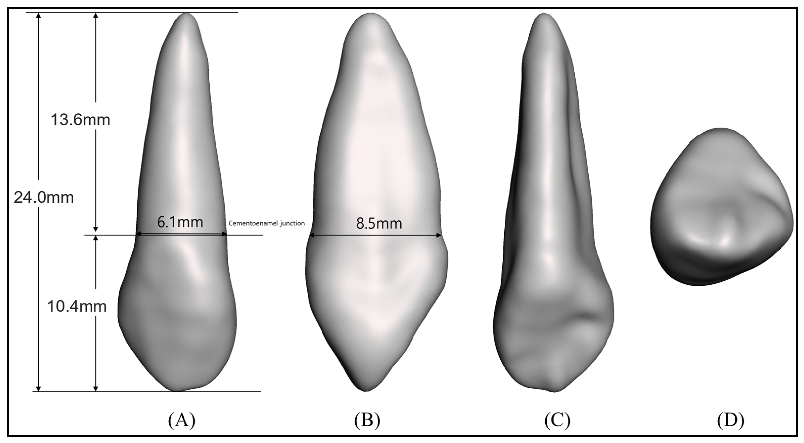
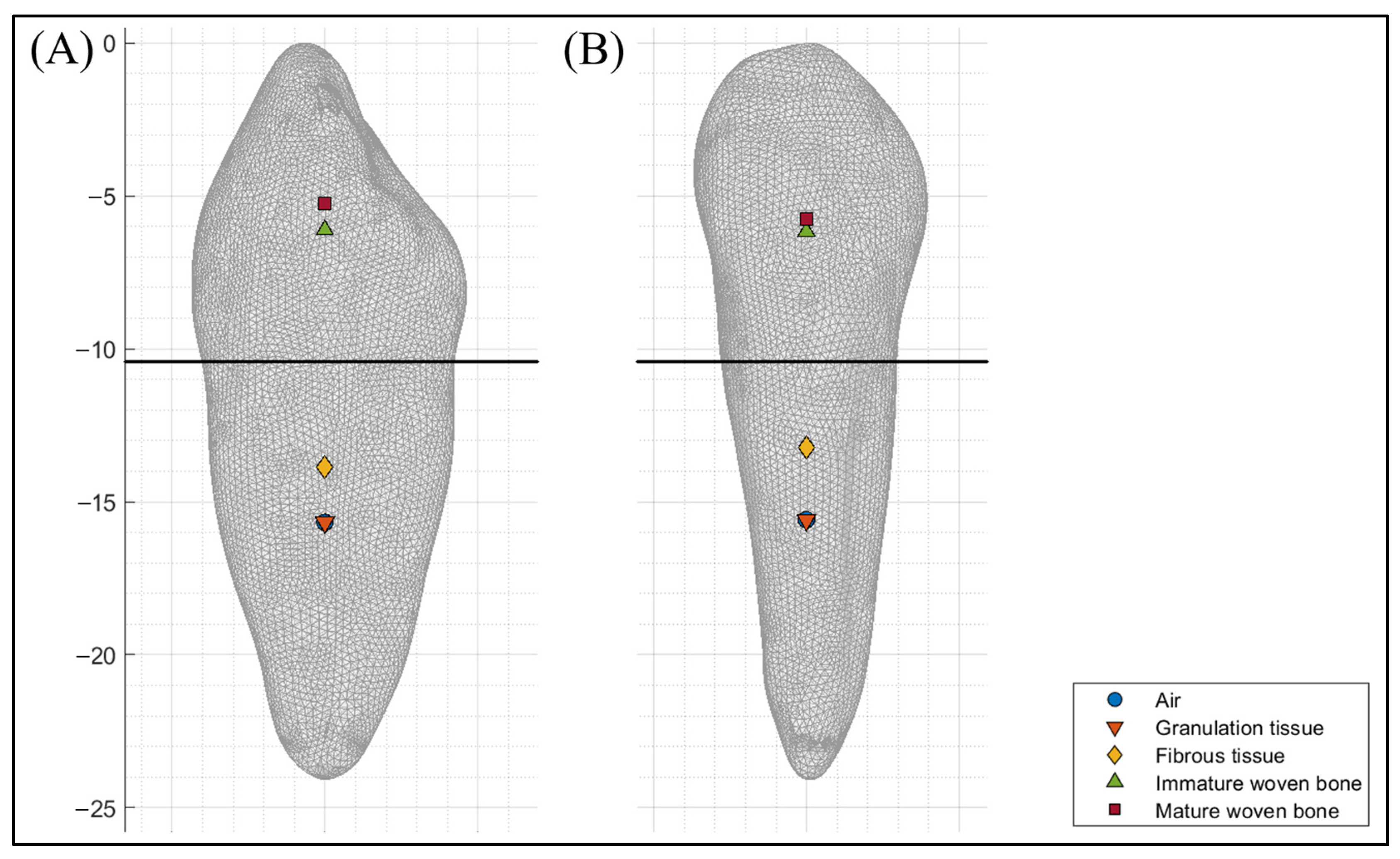
- At the beginning of healing, the COR of the MD and BL direction was located at 38.1% and 38.7% of the root length from the cementoenamel junction, respectively.
- At the second stage of healing, the COR of the MD and BL direction was located at 20.8% and 25.5% of the root length from the cementoenamel junction, respectively.
- At the third stage of healing, the COR of the MD and BL direction was located at 40.8% and 41.3% of the crown length from the cementoenamel junction, respectively.
- At the end of healing, the COR of the MD and BL direction was located at 44.6% and 49.8% of the crown length from the cementoenamel junction, respectively.
Author Contributions
Funding
Institutional Review Board Statement
Informed Consent Statement
Data Availability Statement
Conflicts of Interest
References
- Kokich, V.G.; Mathews, D.P. Surgical and orthodontic management of impacted teeth. Dent. Clin. North Am. 1993, 37, 181–204. [Google Scholar] [CrossRef] [PubMed]
- Thilander, B.; Jakobsson, S. Local factors in impaction of maxillary canines. Acta Odontol. Scand. 1968, 26, 145–168. [Google Scholar] [CrossRef] [PubMed]
- Laganà, G.; Venza, N.; Borzabadi-Farahani, A.; Fabi, F.; Danesi, C.; Cozza, P. Dental anomalies: Prevalence and associations between them in a large sample of non-orthodontic subjects, a cross-sectional study. BMC Oral Health 2017, 17, 1–7. [Google Scholar] [CrossRef] [PubMed]
- Ku, J.H.; Han, B.; Kim, J.; Oh, J.; Kook, Y.-A.; Kim, Y. Common dental anomalies in Korean orthodontic patients: An update. Korean J. Orthod. 2022, 52, 324–333. [Google Scholar] [CrossRef]
- Uslu, O.; Akcam, M.O.; Evirgen, S.; Cebeci, I. Prevalence of dental anomalies in various malocclusions. Am. J. Orthod. Dentof. Orthop. 2009, 135, 328–335. [Google Scholar] [CrossRef]
- Patil, S.; Maheshwari, S. Prevalence of impacted and supernumerary teeth in the North Indian population. J. Clin. Exp. Dent. 2014, 6, e116–e120. [Google Scholar] [CrossRef]
- Mucedero, M.; Rozzi, M.; Di Fusco, G.; Danesi, C.; Cozza, P. Morphometric analysis of the palatal shape and arch dimension in subjects with buccally displaced canine. Eur. J. Orthod. 2020, 42, 544–550. [Google Scholar] [CrossRef]
- Oh, S.; Kim, Y.I.; Kim, S.S.; Park, S.B.; Kim, S.H. Comparison of root apex’s position between unilateral and bilateral palatally impacted canines: A pilot study. Am. J. Orthod. Dentof. Orthop. 2023, 163, 311–318. [Google Scholar] [CrossRef]
- Jo, W.; Lee, N.; Lee, S. A statistical study on characteristics and treatment of child and adolescent patients with tooth impaction. J. Korean Acad. Pediatr. Dent. 2014, 41, 306–313. [Google Scholar] [CrossRef]
- Bishara, S.E.; Kommer, D.D.; McNeil, M.H.; Montagano, L.N.; Oesterle, L.J.; Youngquist, H.W. Management of impacted canines. Am. J. Orthod. 1976, 69, 371–387. [Google Scholar] [CrossRef]
- Cruz, R.M. Orthodontic traction of impacted canines: Concepts and clinical application. Dental Press J. Orthod. 2019, 24, 74–87. [Google Scholar] [CrossRef]
- Cassina, C.; Papageorgiou, S.N.; Eliades, T. Open versus closed surgical exposure for permanent impacted canines: A systematic review and meta-analyses. Eur. J. Orthod. 2018, 40, 1–10. [Google Scholar] [CrossRef]
- Kapila, S.D. Cone Beam Computed Tomography in Orthodontics; Wiley-Blackwell: Ann Arbor, MI, USA, 2014. [Google Scholar]
- Gandhi, V.; Luu, B.; Dresner, R.; Pierce, D.; Upadhyay, M. Where is the center of resistance of a maxillary first molar? A 3-dimensional finite element analysis. Am. J. Orthod. Dentof. Orthop. 2021, 160, 442–450. [Google Scholar] [CrossRef]
- Choy, K.; Pae, E.K.; Park, Y.; Kim, K.H.; Burstone, C.J. Effect of root and bone morphology on the stress distribution in the periodontal ligament. Am. J. Orthod. Dentof. Orthop. 2000, 117, 98–105. [Google Scholar] [CrossRef] [PubMed]
- Vollmer, D.; Bourauel, C.; Maier, K.; Jäger, A. Determination of the centre of resistance in an upper human canine and idealized tooth model. Eur. J. Orthod. 1999, 21, 633–648. [Google Scholar] [CrossRef] [PubMed]
- Liu, X.; Liu, M.; Wu, B.; Liu, J.; Tang, W.; Yan, B. Effect of the Maxillary Sinus on Tooth Movement during Orthodontics Based on Biomechanical Responses of Periodontal Ligaments. Appl. Sci. 2022, 12, 4990. [Google Scholar] [CrossRef]
- Prasad, K.N.; Shivamurthy, P.; Sagarkar, R. Orthodontic Displacement and Stress Assessment: A Finite Element Analysis. World J. Dent. 2017, 8, 407–412. [Google Scholar] [CrossRef]
- Zeno, K.G.; Mustapha, S.; Ayoub, G.; Ghafari, J.G. Effect of force direction and tooth angulation during traction of palatally impacted canines: A finite element analysis. Am. J. Orthod. Dentof. Orthop. 2020, 157, 377–384. [Google Scholar] [CrossRef]
- Lena Sezici, Y.; Gediz, M.; Akış, A.A.; Sarı, G.; Duran, G.S.; Dindaroğlu, F. Displacement and stress distribution of Kilroy spring and nickel-titanium closed-coil spring during traction of palatally impacted canine: A 3-dimensional finite element analysis. Orthod. Craniofac. Res. 2020, 23, 471–478. [Google Scholar] [CrossRef]
- Burstone, C.J.; Pryputniewicz, R.J. Holographic determination of centers of rotation produced by orthodontic forces. Am. J. Orthod. 1980, 77, 396–409. [Google Scholar] [CrossRef]
- Choy, K.; Kim, K.H.; Burstone, C.J. Initial changes of centres of rotation of the anterior segment in response to horizontal forces. Eur. J. Orthod. 2006, 28, 471–474. [Google Scholar] [CrossRef] [PubMed]
- Woo, J.Y.; Park, Y.C. Experimental study of the vertical location of the centers of resistance for maxillary anterior teeth during retraction using the laser reflection technique. Korean J. Orthod. 1993, 23, 375–389. [Google Scholar]
- Kwak, K.H.; Oh, S.; Choi, Y.K.; Kim, S.H.; Kim, S.S.; Park, S.B.; Kim, Y.I. Effects of different distalization directions and methods on maxillary total distalization with clear aligners: A finite element study. Angle Orthod. 2023, 93, 348–356. [Google Scholar] [CrossRef]
- Zhu, G.Y.; Zhang, B.; Yao, K.; Lu, W.X.; Peng, J.J.; Shen, Y.; Zhao, Z.H. Finite element analysis of the biomechanical effect of clear aligners in extraction space closure under different anchorage controls. Am. J. Orthod. Dentof. Orthop. 2023, 163, 628–644. [Google Scholar] [CrossRef]
- Geiger, M.E.; Lapatki, B.G. Locating the center of resistance in individual teeth via two-and three-dimensional radiographic data. J. Orofac. Orthop. 2014, 75, 96–106. [Google Scholar] [CrossRef] [PubMed]
- Huang, H.; Tang, W.; Yan, B.; Wu, B.; Cao, D. Mechanical responses of the periodontal ligament based on an exponential hyperelastic model: A combined experimental and finite element method. Comput. Methods Biomech. Biomed. Engin. 2016, 19, 188–198. [Google Scholar] [CrossRef] [PubMed]
- Ghiasi, M.S.; Chen, J.E.; Rodriguez, E.K.; Vaziri, A.; Nazarian, A. Computational modeling of human bone fracture healing affected by different conditions of initial healing stage. BMC Musculoskelet. Disord. 2019, 20, 1–14. [Google Scholar] [CrossRef]
- Liu, L.; Zhan, Q.; Zhou, J.; Kuang, Q.; Yan, X.; Zhang, X.; Shan, Y.; Li, X.; Lai, W.; Long, H. Effectiveness of an anterior mini-screw in achieving incisor intrusion and palatal root torque for anterior retraction with clear aligners: A finite element study. Angle Orthod. 2021, 91, 794–803. [Google Scholar] [CrossRef]
- Araújo, M.G.; Silva, C.O.; Misawa, M.; Sukekava, F. Alveolar socket healing: What can we learn? Periodontol. 2000 2015, 68, 122–134. [Google Scholar] [CrossRef]
- Meyer, B.N.; Chen, J.; Katona, T.R. Does the center of resistance depend on the direction of tooth movement? Am. J. Orthod. Dentof. Orthop. 2010, 137, 354–361. [Google Scholar] [CrossRef]
- Fish, G.D. Some Engineering Principles of Possible Interest to Orthodontists; SS White Dental Manufacturing Company: Philadelphia, PA, USA, 1917. [Google Scholar]
- Mulligan, T.F. Common sense mechanics. J. Clin. Orthod. 1979, 13, 676–683. [Google Scholar] [PubMed]
- Smith, R.J.; Burstone, C.J. Mechanics of tooth movement. Am. J. Orthod. 1984, 85, 294–307. [Google Scholar] [CrossRef] [PubMed]
- Provatidis, C.G. Numerical estimation of the centres of rotation and resistance in orthodontic tooth movement. Comput. Methods Biomech. Biomed. Engin. 1999, 2, 149–156. [Google Scholar] [CrossRef] [PubMed]
- Bourauel, C.; Keilig, L.; Rahimi, A.; Reimann, S.; Ziegler, A.; Jäger, A. Computer-aided analysis of the biomechanics of tooth movements. Int. J. Comput. Dent. 2007, 10, 25–40. [Google Scholar] [PubMed]
- Berkovitz, B. The structure of the periodontal ligament: An update. Eur. J. Orthod. 1990, 12, 51–76. [Google Scholar] [CrossRef] [PubMed]


| Young’s Modulus (MPa) | Poisson’s Ratio | |
|---|---|---|
| Periodontal ligament | 0.05 | Ogden 1st model |
| Tooth | 19,600 | 0.3 |
| Bone | 17,000 | 0.3 |
| Granulation tissue | 0.001 | 0.17 |
| Fibrous tissue | 2 | 0.17 |
| Immature woven bone | 1000 | 0.3 |
| Mature woven bone | 6000 | 0.3 |
| Pericoronal Tissue | Location from the Cementoenamel Junction (mm) | Percentage of Root/Crown Length (%) | ||
|---|---|---|---|---|
| MD | BL | MD | BL | |
| Air | −5.18 * | −5.26 * | 38.1% † | 38.7% † |
| Granulation tissue | −5.18 * | −5.26 * | 38.1% † | 38.7% † |
| Fibrous tissue | −2.82 * | −3.46 * | 20.8% † | 25.5% † |
| Immature woven bone | 4.25 | 4.30 | 40.8% ‡ | 41.3% ‡ |
| Mature woven bone | 4.64 | 5.18 | 44.6% ‡ | 49.8% ‡ |
Disclaimer/Publisher’s Note: The statements, opinions and data contained in all publications are solely those of the individual author(s) and contributor(s) and not of MDPI and/or the editor(s). MDPI and/or the editor(s) disclaim responsibility for any injury to people or property resulting from any ideas, methods, instructions or products referred to in the content. |
© 2023 by the authors. Licensee MDPI, Basel, Switzerland. This article is an open access article distributed under the terms and conditions of the Creative Commons Attribution (CC BY) license (https://creativecommons.org/licenses/by/4.0/).
Share and Cite
Oh, S.; Choi, Y.-K.; Kim, Y.-I.; Kim, S.-S.; Park, S.-B.; Kim, S.-H. The Center of Resistance of an Impacted Maxillary Canine: A Finite Element Analysis. Appl. Sci. 2023, 13, 11256. https://doi.org/10.3390/app132011256
Oh S, Choi Y-K, Kim Y-I, Kim S-S, Park S-B, Kim S-H. The Center of Resistance of an Impacted Maxillary Canine: A Finite Element Analysis. Applied Sciences. 2023; 13(20):11256. https://doi.org/10.3390/app132011256
Chicago/Turabian StyleOh, Sewoong, Youn-Kyung Choi, Yong-Il Kim, Seong-Sik Kim, Soo-Byung Park, and Sung-Hun Kim. 2023. "The Center of Resistance of an Impacted Maxillary Canine: A Finite Element Analysis" Applied Sciences 13, no. 20: 11256. https://doi.org/10.3390/app132011256
APA StyleOh, S., Choi, Y.-K., Kim, Y.-I., Kim, S.-S., Park, S.-B., & Kim, S.-H. (2023). The Center of Resistance of an Impacted Maxillary Canine: A Finite Element Analysis. Applied Sciences, 13(20), 11256. https://doi.org/10.3390/app132011256