Article

Large-Scale Experimental Static Testing on 50-Year-Old Prestressed Concrete Bridge Girders

1
Department of Structural, Geotechnical and Building Engineering, Politecnico di Torino, 10129 Torino, Italy
2
Department of Civil and Environmental Engineering, Politecnico di Milano, 20133 Milano, Italy
*
Author to whom correspondence should be addressed.
Appl. Sci. 2023, 13(2), 834; https://doi.org/10.3390/app13020834
Submission received: 12 December 2022 / Revised: 4 January 2023 / Accepted: 5 January 2023 / Published: 7 January 2023
(This article belongs to the Special Issue Existing Bridges: From Inspection to Structural Rehabilitation)

Abstract

:
The heritage of existing road infrastructures and in particular of bridges consists of structures that are approaching or exceeding their designed service life. Detrimental causes such as aging, fatigue and deterioration processes other than variation in loading conditions introduce uncertainties that make structural assessment a challenging task. Experimental data on their performances are crucial for a proper calibration of numerical models able to predict their behavior and life-cycle structural performance. In this scenario, an experimental research program was established with the aim of investigating a set of 50-year-old prestressed concrete bridge girders that were recovered from a decommissioned bridge. The activities included initial non-destructive tests, and then full-scale load tests followed by a destructive test on the material samples. This paper reports the experimental results of the full-scale tests conducted on the first group of four I-beams assumed to be in good condition from visual inspection at the time of testing. Loading tests were performed using a specifically designed steel reaction frame and a test setup equipment, as detailed in the present work. Due to the structural response of this first group of girders, a uniform behavior was found at both service and ultimate conditions. The failure mechanism was characterized by the crushing of the cast-in-situ top slab corresponding to a limited deflection, highlighting a non-ductile behavior. The outcomes of the experimental research are expected to provide new data for the life-cycle safety assessment of existing bridges through an extended database of validated experimental tests and models.

1. Introduction

The development of road transport systems is an essential factor in all modern economies. Transportation networks play an important role in increasing production, employment and accessibility where bridges are critical components [1]. Most prestressed concrete (PC) bridges were constructed from the early post-World War II period onwards, when the shortage of steel production capacity provided a great impetus to the use of PC in Europe. Although PC girders have been used for more than 50 years and therefore some of them have exceeded their design service life, relatively little experimental data on their structural performance through experimental tests are available. At a time when the aging bridge implies an increase in maintenance costs, data on their long-term structural performance are crucial for management agencies to aid decision-making policies. The current maintenance and strengthening of existing bridges commonly rely on routine visual inspections and condition indices based on damage models. However, some types of deterioration of PC bridges cannot be detected by visual inspection. PC structures have highly time-dependent properties, such as the shrinkage and creep of concrete and the relaxation of the prestressing strands. Indeed, in the phase construction, precast–prestressed beams are connected to casting in place top slabs and then the interaction of long-term effects can lead to time-dependent stress redistributions. In addition, corrosion phenomena can affect the mechanical properties of materials and the bond capacities of prestressing strands. In order to perform a reliable life-cycle structural assessment and evaluation of the residual service life of existing bridges, it is necessary to analyze the long-term properties of materials, prestressing losses, degradation effects and damages at a large extent heading to a statistical analysis [2]. To date, full-scale destructive load testing on bridge structures, including the characterization of materials, has been reported in the literature, but it focused on a limited number of samples.
Pepè et al. [3] conducted a full-scale loading test of three beams taken from the 45-year-old Sorell Causeway, a 457 m long PC road bridge in Australia. They found a clear correlation between the reduction in load capacity and the beams that visually appeared to be more severely affected by cracking and corrosion. To accumulate data on existing PC bridges, Jeon et al. [4] conducted an experimental program on full-sized and deteriorated 45-year-old PC bridge girders. To find out the mechanical properties of concrete, the girder was cut at every 1 m after the loading test, and a total of 120 specimens for concrete cylinder testing were taken through concrete coring. Concrete strength in the longitudinal and transversal directions showed similar and higher values than the design strength. Eder et al. [5] tested two 50-year-old 13.7 m long precast, post-tensioned concrete bridge I-girders to investigate the effectiveness of the composite section. Lundqvist et al. [6] tested the remaining tendon forces in five 30-year-old PC beams of the Olkiluoto nuclear power plant in Finland. The prestress losses obtained in the tests were higher than the values obtained in the prediction models, probably linked to their specific environment. Taffe et al. [7] presented the condition assessment of a 45-year-old PC bridge, demolished after showing severe damage in the prestressing steel and reinforcements. To investigate bridge decks for a reliable detection of fractures in tendon ducts, they developed a tractor appliance combined with the “Magnetic Flux Leakage” testing method, which was able to magnetize the tendon ducts and collecting data. Shenoy et al. [8] carried out a structural load test on two PC box beams removed from a 27-year-old bridge with span length of 16.5 m. Although one beam had evidence of minor deterioration, the load–deflection curves of both beams had a ductile behavior and flexural strength greater than the expected values. Zwicky [9] tested three PC beams of 21 m in length recovered from the replacement of a 30-year-old bridge deck. Different experimental sets-up were considered aimed at predicting bending and shear resistance. Shear failure was more difficult to predict due to dependency on the scatter in material properties and simplified assumptions in the modelling. Dasar et al. [10] investigated the effect of cracks on six pre-cracked PC beams after 20 years of exposure to a marine environment. The experimental results revealed that prestress loss was increased due to degradation, with a pre-cracking of 24% for post-tensioned beams and 30% for pre-tensioned beams. Kramer et al. [11] reported and commented the condition of a PC bridge demolished after a 54-year service life for insufficient vertical and horizontal clearance. The visual inspection that occurred after the demolition showed that the prestressing ducts were not fully grouted. The concrete cores revealed higher concrete strengths of 50% and more than the design values. Azizinamini et al. [12] proposed a method to measure the prestressing force based on the stress state around a small cylindrical hole drilled in the bottom flange of a prestressed girder. The results of the cracking test conducted on a 25-year-old PC girder indicate the promising innovation of the new non-destructive method. Halsey et al. [13] carried out a destruction experiment on two PC inverted T-beam removed from a 40-year-old bridge with a span length of 7.62 m. The tests revealed that a full composite action was achieved, even though the surface of the beams was not roughened and stirrups were provided as required by AASHTO specifications. Jin-liang and Yan-min [14] conducted a loading test for four pieces of 16 m prestressed concrete hollow plate that were used for 20 years in a freezing–thawing region. Tests on the material strength showed that the performances can meet the requirements specified in the design. Moving from a pure bending load to third-point loading, the beams failed for concrete crushing at the top edge of the bending zone or for sharing-compression caused by the slippage of pre-stressed reinforcement. Rao et al. [15] subjected two precast PC box beams removed from a 27-year-old bridge with a span length of 17.1 m to fatigue testing. Cycling to a strand stress range limit of 0.06 fpu recommended by ACI Committee 215, the beams retained excellent performance after 1,500,000 cycles, whereas cycling with a stress range of 0.11 fpu caused fatigue failure of strand wires after 145,000 cycles. Recupero et al. [16] carried out an experimental test to study the influence of tendon corrosion on the response behavior of structural elements. Artificial defects were induced by introducing a chemical solution or acid into the duct, reducing the load-bearing capacity to half the load achieved for the control beam. Pessiki et al. [17] determined the effective prestress force in two PC beams removed from a bridge after a period of 28 years in service. The prestress loss obtained from an elastic analysis based on the average decompression load was 60 percent of the code-predicted value. Botte et al. [18] carried out large-scale destructive tests on PC beams recovered from industrial buildings at an age of 70 years. Shu et al. [19] conducted full-scale in-situ destructive tests of a 55-year-old reinforced concrete bridge deck slab on PC girders to calibrate models of one-way shear and punching shear resistance. Pepe et al. [20] performed load tests to destruct three deteriorated PC beams recovered from a 45-year-old bridge exposed to an aggressive marine environment. The load–response behavior showed that none of the beams reached the expected design capacity; the collapse was anticipated by a progressive failure of the prestressing wires.
All the reported works were concerned with the analysis of a limited number of structural elements and only four cases referred to bridges of more than 50 years of age. The present study reports the experimental results of large-scale load tests on the first four PC beams retrieved from a 50-year-old viaduct exposed to environmental actions and service loads. The Corso Grosseto viaduct was located in Turin, Italy, in a strategic hub of the city characterized by a dense context of residential buildings and road network. In September 2018, the viaduct was deconstructed following a long period of restoration and durability problems for new urban redevelopment and different mobility needs [21]. After demolition, a joint research program named BRIDGE|50 was set up to study 29 PC beams (25 I-beams and 4 box beams) and two pier caps [22,23,24]. The elements were stored in a testing site as described in Anghileri et al. [25]. The testing site was properly equipped to perform an extensive study of non-destructive tests and full-scale load tests. Concrete new jerseys were placed to support the structural elements under the original static scheme. Furthermore, a large reaction steel frame of the Interdepartmental Center for the Safety of Infrastructures and Constructions (SISCON) of Politecnico di Torino was used to perform the full-scale tests with different loading configurations. The layout of the measuring equipment was designed to measure key parameters representative of the structural response of the elements during the loading test. The BRIGDE|50 research project has a unique value for the high number of structural elements under investigation for a structural typology widely adopted all around the world and the large amount of collected data. The outcomes of the research project will be useful to develop a more reliable assessment of the remaining service life of bridges.

2. Case Study

2.1. Corso Grosseto Viaduct

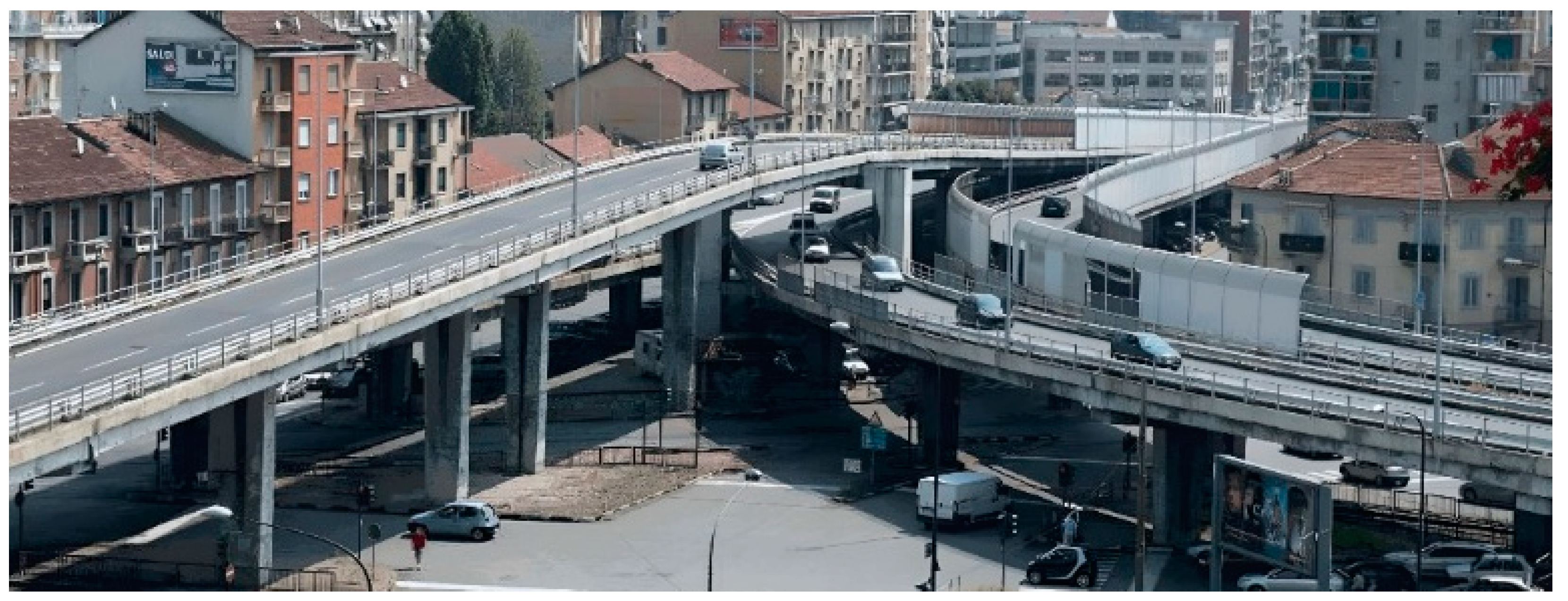
The Corso Grosseto viaduct, built in Turin (Italy) in 1970, was a multilevel road interchange developed along two main lines, the Corso Grosseto West–Corso Grosseto East route and the Corso Potenza–Corso Grosseto East route. Each route was linked by two structurally independent decks, one for each carriageway. The viaduct consisted of 80 simply supported spans, ranging from 16 to 24 m, for a total length of about 1.4 km (Figure 1).
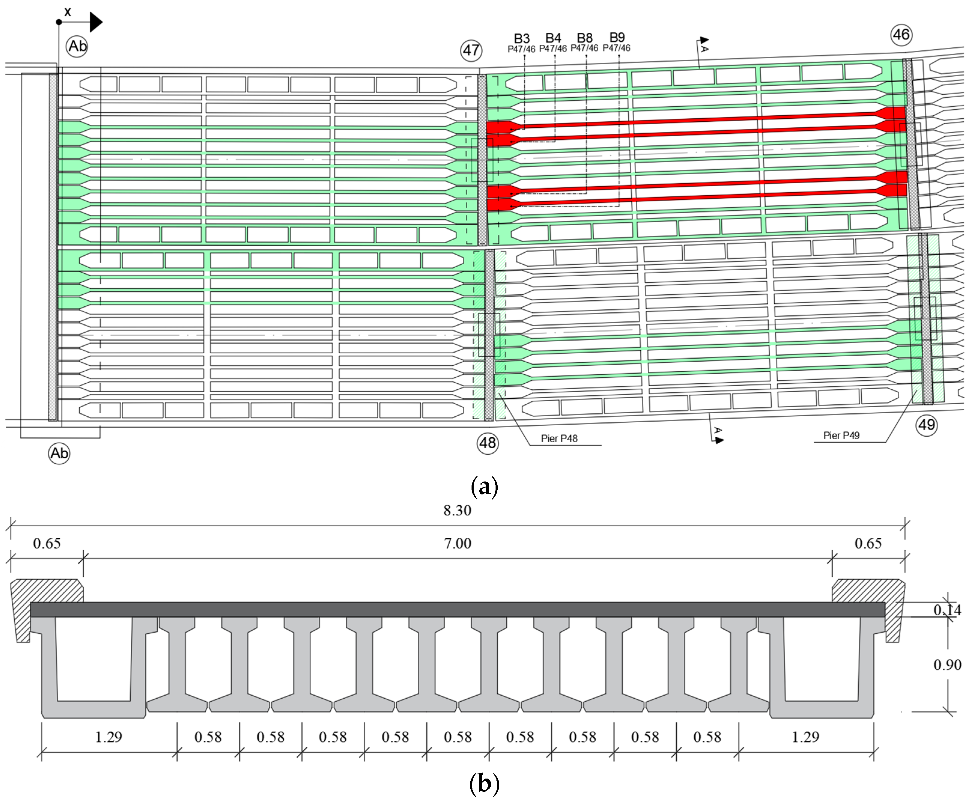
The deck of each span consisted of 10 precast PC I-beams and 2 U beams all connected by a cast in situ slab, with transverse beams at third points of each span. Figure 2 shows a technical drawing of the top view and cross-section of the viaduct. The elements retrieved for the project are depicted in Figure 2a in green, whereas the elements tested, whose results are reported in this paper, are painted in red.
The girders had an average span length of 19.2 m. According to the design documentation [26], the girders were pretensioned using 17 strands along the bottom flange, distributed on two rows, and 3 strands on the top flange with a nominal diameter of 12.7 mm, as reported in Figure 3. In the bottom flange, three strands from 0 to 5 m and two from 0 to 3 m starting from the end sections were unbonded using ducts. The shear reinforcement consisted of ∅8 mm stirrups with 250 mm spacing. The stirrups were also used to connect the precast beam with the cast in situ top deck slab.
The edge beams (Figure 2b) with a box section (U-beam with slab) consisted of two I-girders coupled together in terms of resisting section and reinforcement. The piers were T-shaped and reached a maximum height of 12.40 m. The pier caps were post-tensioned with multiple groups of smooth wires along a curved profile. A group of tendons was released before placing the beams, and secondary prestressing was induced before the application of non-structural loads.
Construction reports specified a characteristic tensile strength of prestressing steel of 1638 MPa and a concrete compressive strength of 30 MPa at 28 days. The maximum allowable stress for the strands immediately after tensioning was 1400 MPa. The total prestress loss was estimated at the design stage as 36.8% of the initial stress after tensioning. Based on the original design data, the material properties were chosen according to the allowable stress design, assuming an acting bending moment on the most stressed girders of 824 kNm due to the live loads.
The exposure to aggressive atmospheric agents linked to a massive use of de-icing salts has led, over the years, to evident problems of durability and several conservative maintenance operations. In July 2017, the complete closure to vehicular transit was settled to start the deconstruction process following new urban redevelopment and different mobility needs.

2.2. BRIDGE|50 Research Project

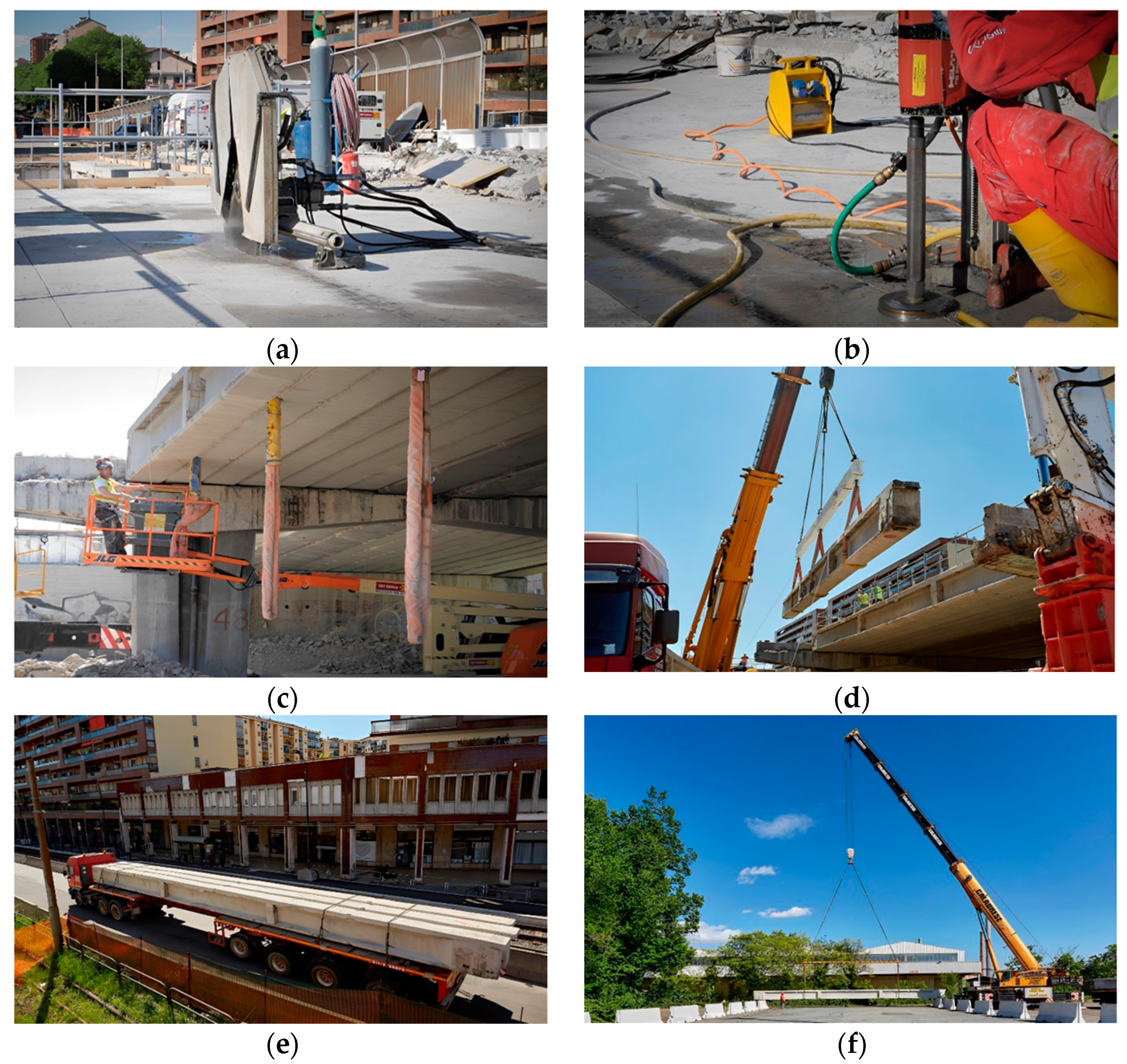
BRIDGE|50 is a project based on a research agreement established in 2018 between Politecnico di Milano, Politecnico di Torino and several public authorities and private companies [22,23,24]. A project management committee involving all partners was established and the research activities are conducted jointly by Politecnico di Milano and Politecnico di Torino. The project aims at investigating the residual structural performance of the 50-year-old Corso Grosseto viaduct and supporting, in this way, the safety assessment and residual lifetime evaluation of existing bridges based on experimental tests and numerical investigations. A wide experimental campaign is ongoing on the set of structural elements collected during the dismantlement phases, including diagnostic non-destructive test, full-scale load tests, dynamic tests, laboratory test on material samples, and conventional and innovative techniques to assess the actual condition of the structural members from both chemical and mechanical points of view. The testing site was set up in Turin under the supervision of the Politecnico di Torino. The deconstruction process involved cutting, lifting and transportation phases. Adjacent longitudinal PC beams were separated cutting the concrete slab using disks and diamond wires. A drilling machine was adopted to drill the bridge deck and insert the sling ropes to lift the deck beams. Exceptional transports by truck were adopted to move 25 I-beams, 4 box beams and 2 pier caps to the testing site. In Figure 4, some pictures of different phases are shown.
A proper identification code reported in Figure 2 was assigned for each structural member to record the element position on the original location.

2.3. Experimental Program

The first stage of the research project involved a series of preliminary activities conducted before the dismantling of the viaduct in order to obtain a general overview on the conservation state. These activities concern visual inspections, conducted according to national and international standards [27], concrete coring from piers followed by carbonation tests and reinforcing bar sampling. Finally, dynamic test was carried out on the four spans (reported in Figure 2) before the dismantling in order to characterize the global dynamic behavior of the decks of the viaduct [28]. These preliminary results will be compared and validated with the outcome gathered after the experimental tests conducted at the testing site.
The collected elements were subjected to an extensive on-site diagnostic study, including the mapping of the degradation pattern, drone surveys, rebound hammer test, magnetometric, ultrasonic investigations and electrochemical methods to evaluate corrosion potential and corrosion rate. Additional information about dynamic analyses and non-destructive testing can be found in previously published papers [28,29,30,31,32,33,34]. The results of the non-destructive diagnostic study were used to distinguish three different categories, such as undamaged beams, deteriorated beams by corrosion and beams with damage induced by dismantling operations. Relying on these three classes, loading tests were scheduled, starting with beams showing a low level of damage of the cast in situ slab generated by lifting preparation [31,32] (Figure 5).
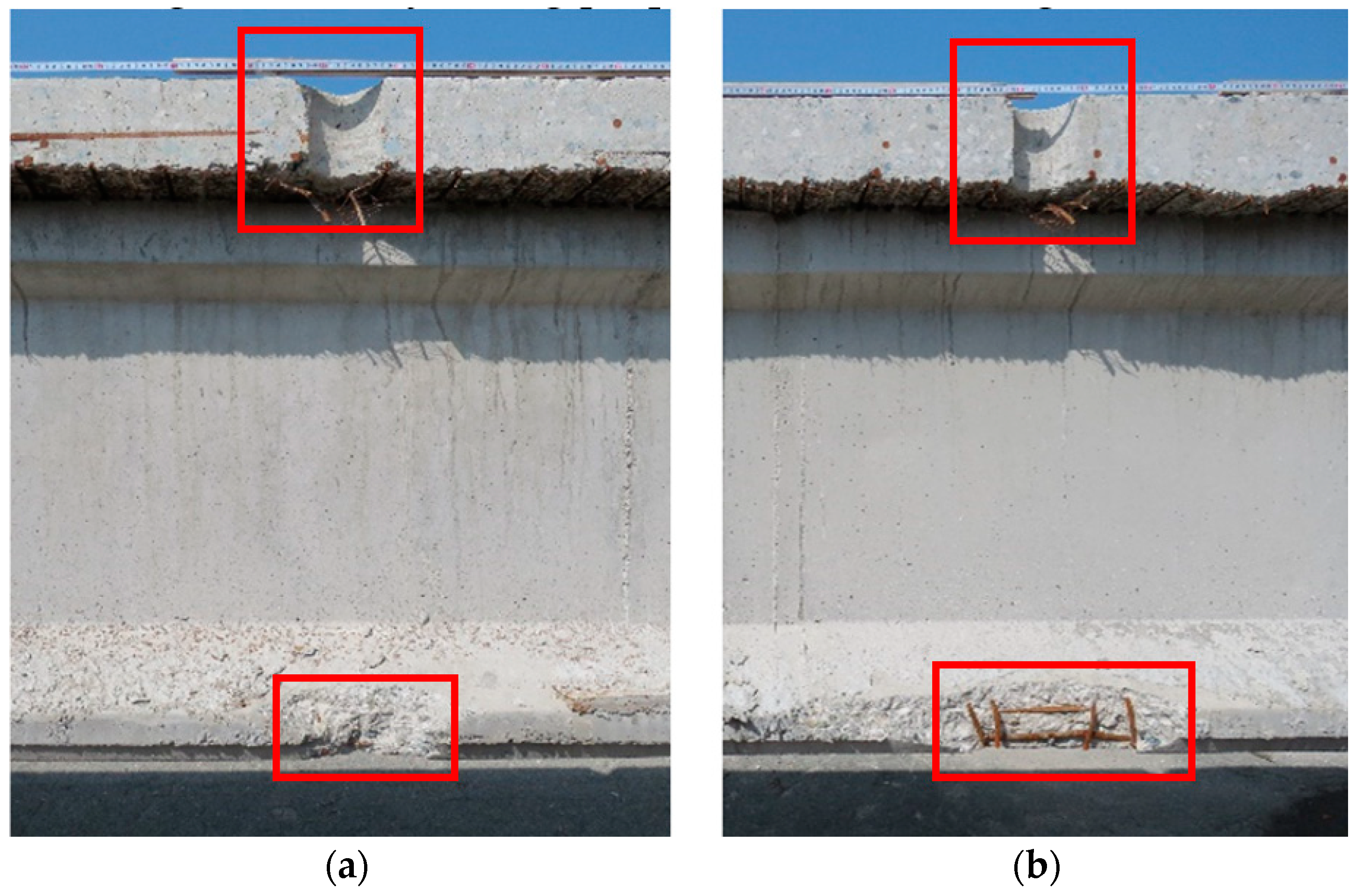
The tests reported in this paper involved B3-P47/46, B8-P47/46, B4-P47/46 and B9-P47/46 beams, classified as a girder in good condition, where BX-PYY/ZZ means: B is for I-shape section beams, X is the progressive numbering of I beams in the transverse section of the deck, and PYY/ZZ is the starting support, where P means pier and the following letters are the numbering of the support number (see Figure 2). As previously reported, small portions of the deck slab and bottom flange concrete at about 4 m from each beam end were damaged for lifting operations (red square in Figure 5). Girders B3-B4-B8-P47/46 and B9-P47/46 had no damage in the midspan zone and no damage in what concerns the bottom flange with no cutting of the strands. Other girders also had an induced damage caused by drilling at midspan and variable cutting of the strands at the bottom flange.
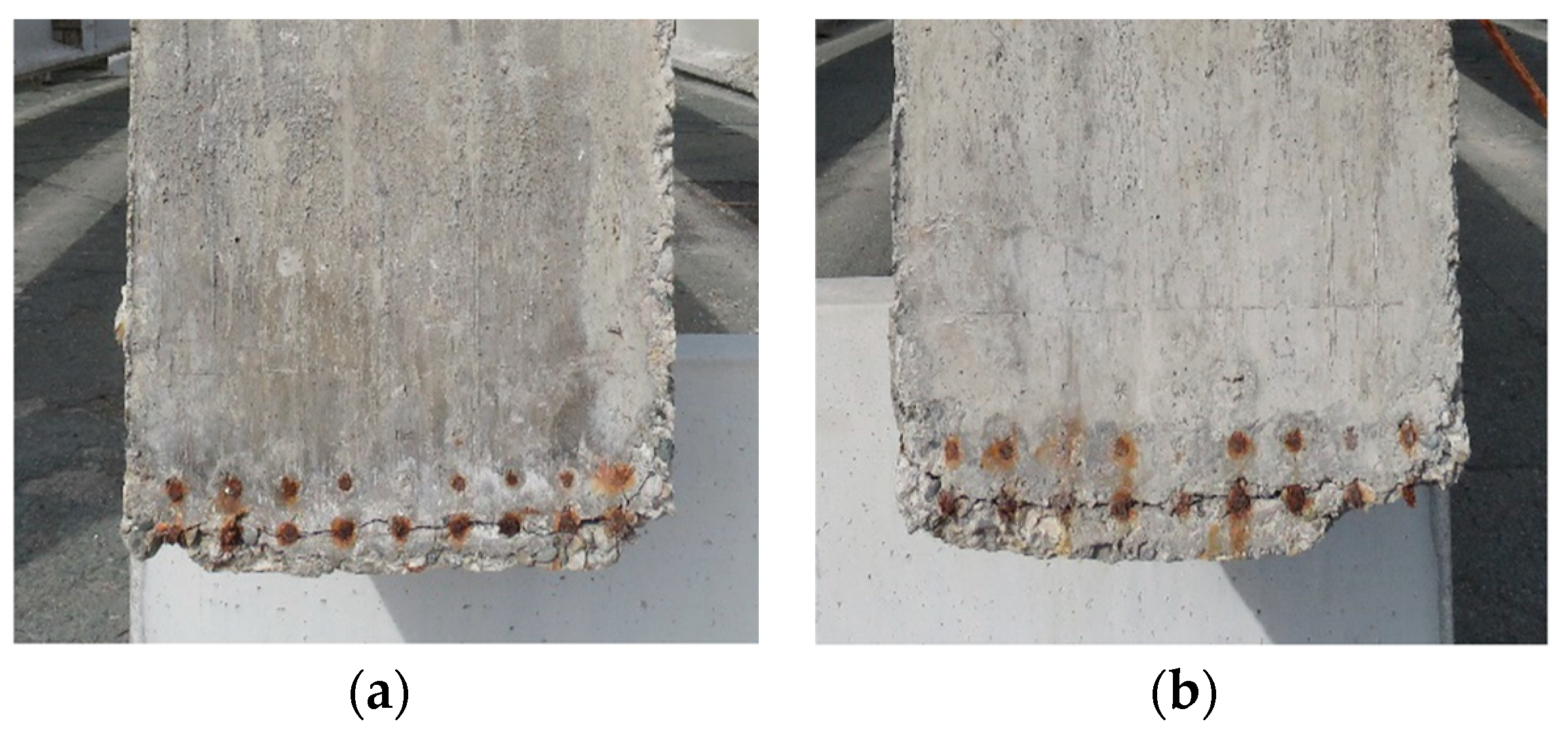
The B3-P47/46 and B4-P47/46 girders showed 5 mm wide horizontal cracks at the edges caused by corrosion activity that transversally crossed the strands (Figure 6). The visual inspections revealed no other corrosion-induced damages. The presence of such kind of damage can be ascribed to the presence of structural joints.
Two different load tests were planned, two-phases and single monotonic loading phase. The two-phase loading tests were designed with a first loading that reaches the stabilized crack opening, followed by complete unloading; subsequently a loading up to the ultimate load capacity or first signs of failure was scheduled. Since the cracking moment and decompression load are key parameters for providing a preliminary estimate of prestress loss, much attention has been paid to detect these quantities. The estimation of the latter will be confirmed by comparing the results with local tests of residual prestressing on the same girders, such as saw-cuts and strand cutting already planned in the test program.
The single monotonic loading test was planned to investigate the structural behavior up to failure without the effects induced by the first loading cycle. The B3-P47/46, B8-P47/46 and B9-P47/46 girders were loaded in two phases. Furthermore, to study the role of the cast in situ top slab and its connection with the precast beam, the girder B9-P47/46 was tested after the removal of the slab by a saw cut. In Table 1, a summary of the load test protocol is reported.

2.4. Material Properties

The archive research on the test laboratory provided the mechanical properties of strands and concrete. The test certificates released in the 1970s by the Testing Laboratory of the Politecnico di Torino show average yielding and ultimate strength values for prestressing steel of 1486 and 1722 MPa, respectively. The compressive strength recorded at the 28-day of the precast I-beams averaged 50.3 MPa over 4 samples, whereas the compressive strength of the cast-in situ slab averaged 40.5 MPa over 7 samples.
To integrate the material properties reported in the available technical documentation and to provide more accurate values, non-destructive tests were performed and reported in [30]. In Table 2, the results of some destructive tests performed by Material and Structures Testing Laboratory MastrLab of Politecnico di Torino and the Testing Lab for Materials, Buildings and Civil Structures of Politecnico di Milano after the large-scale experiments are reported. The following tests were performed:
  • Concrete of girders and slab: 15 compression tests on cylindric samples and 11 indirect tensile tests;
  • Prestressing steel: 8 tensile stress tests.
The extracted samples of the concrete girders refer to the B3-P47/46, B8-P47/46 and B4-P47/46 beams; the samples of the slab were retrieved from the B3-P47/46 and B9-P47/46 beams. The samples of prestressing steel were taken from the B4-P47/46 and B9-P47/46 beams. Table 2 contains a list of the obtained results in terms of mean value and standard deviation.

3. Loading Test Setup

3.1. Reaction Steel Frame

A large steel reaction frame was designed to investigate the structural behavior and load-carrying capacity of the girders with different loading configurations (Figure 7). The test bench was provided by the Center SISCON of Politecnico di Torino for testing structures with a span of up to 30 m.
The PC beams under testing were positioned on the supporting frame (blue color in Figure 7), where specifically designed bridge bearings replicate the simple support static scheme. The hinge and roller have a support plate of 400 × 400 mm and allow for ±4°of rotation; the roller allows a longitudinal displacement of ±150 mm. The base plate of the bearings is bolted to the supporting frames, which in turn are bolted to the main frames (black color in Figure 7). The latter consist of two main longitudinal steel beams, each composed by 5 I-shaped welded steel segments. These segments were built by welding a 2 m high web to 1 m wide flanges with plates stiffeners spaced 1 m. The longitudinal beams are transversally connected by 5 I-shaped elements 1.5 m long. The loading system (red color in Figure 7) is constituted by two couples of hydraulic jacks hosted into steel member hinged to the steel frame with single capacity of 1200 kN and a maximum stroke of 750 mm. The hydraulic jacks, contrasting on the steel member, act on the pushing system, which transfer the load to a steel transverse beam through six 32 mm steel bars. The transverse steel beams were used to transfer the load from each couple of hydraulic load cylinders to the specimen under testing. Both the supporting frame and the loading system can be installed through a bolted connection along the longitudinal beams with a step of 10 cm in order to obtain different loading schemes. The hydraulic testing system allows for the performance of force-controlled loading tests at a controlled loading rate.
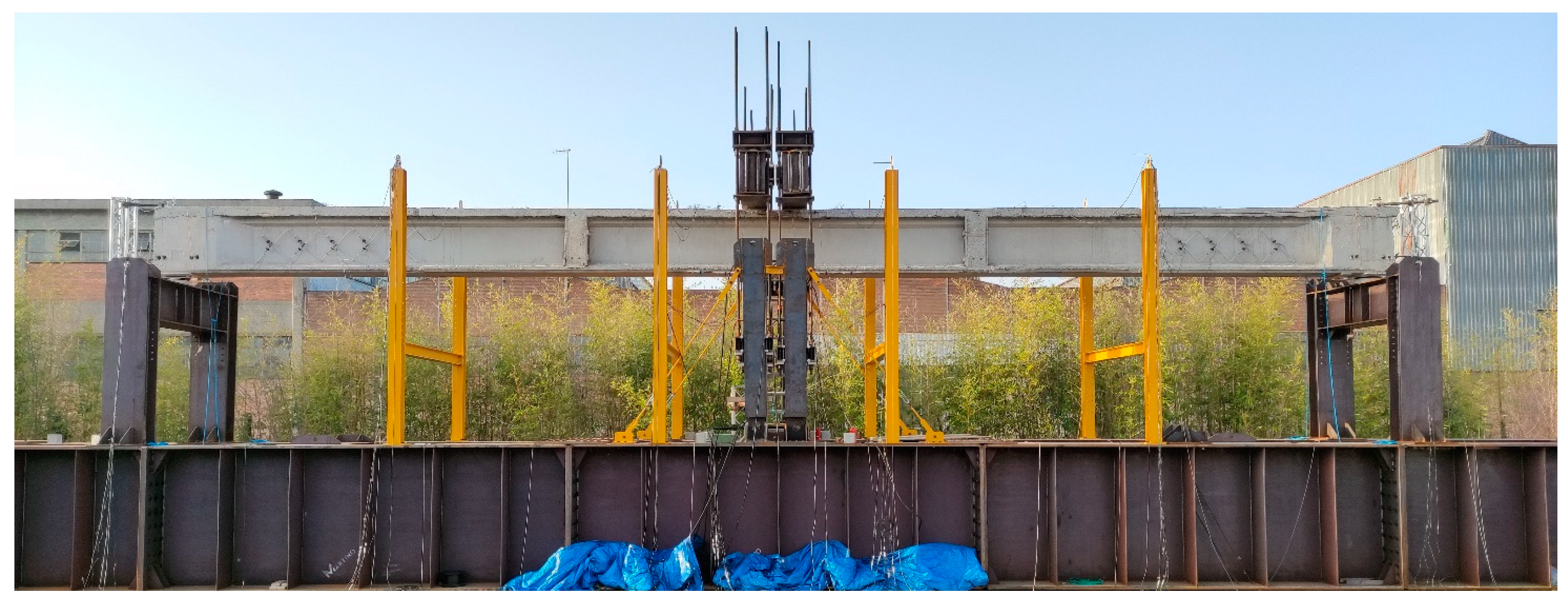
The span length of the flexural tests reported in the present work was 19 m and the two couple of hydraulic jacks were located 0.6 m away from the midspan to conduct the loading tests in a three-point bending type configuration (Figure 8), aimed at investigating the bending resistance of the girders.
Other test configurations will be used in the future to study different failure mechanisms, such as combined bending/shear and pure shear rupture mechanisms.

3.2. Instrumentation

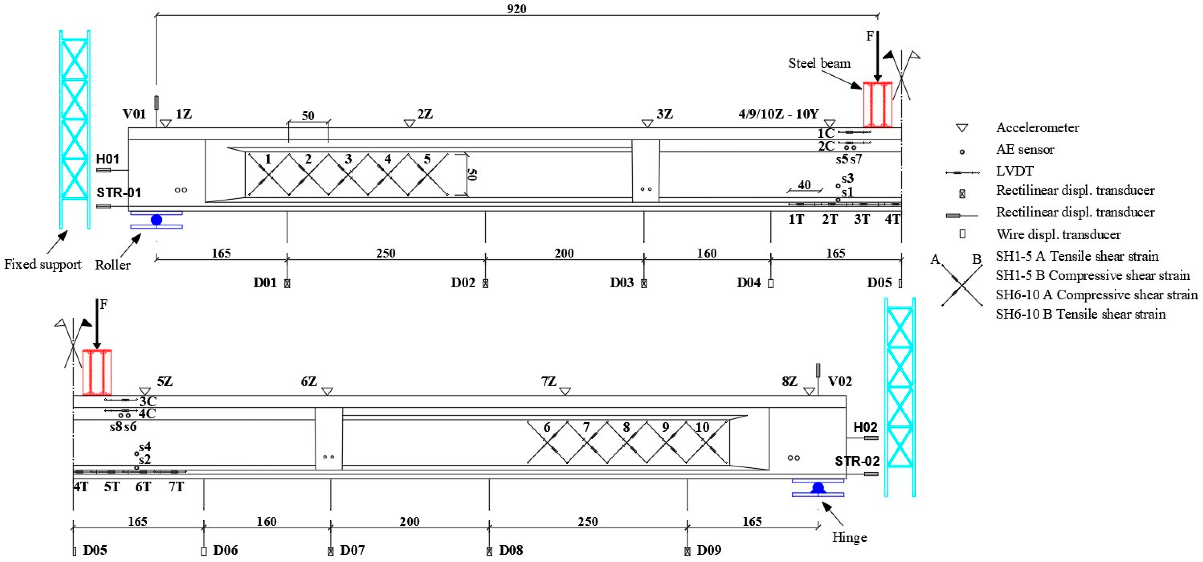
The sensors’ layout was designed to measure key parameters representative of the structural response of the girder during the load test. Table 3 summarizes the details of the designed monitoring system, which consists of 69 devices for measurement of strains, displacements, accelerations, acoustic emissions and forces. In this paper, the results in terms of displacements, strains and forces are presented.
The applied load was measured by load cells on the actuators to read the actual applied load and check the symmetric loading condition. The layout of the sensors for beam B3-P47/46 is reported in Figure 9. The linear variable displacement transducers (LVDTs) were mounted onto two different configurations of the aluminium frame with the aim of measuring the average strain referred to the measurement base: the LVDTs close to the supports are oriented at 45° with a base of 700 mm, whereas the LVDTs in the bending zone were installed with a horizontal direction around the midspan and have a base of 400 mm. The test setup for the first girder B3-P47/6 is shown in Figure 9.
From the second test on the girder B8-P47/46, three out of five pairs of LVDTs were moved close to the transverse beam to intercept a more pronounced cracking pattern evidenced during the first test. For test B9-47/46 (the beam without the cast in situ slab), six out of seven LVDTs were used to measure strains to the bottom flange in bending zone (1T-6T) and two LVDTs in top flange of precast beam (1C and 2C) were moved to the same vertical alignment of 1T and 6T (see Figure 9). Indeed, two strain gauges were used to compare LVDTs measurements in 2C and 1T position. For all the girders, the vertical deflection was measured by nine displacement potentiometer transducers connected to the bottom of the girders (see from D01 to D09 in Figure 9). Furthermore, displacement transducers were installed at the ends of the girders to measure vertical and horizontal displacements, settlement at the supports and the slipping of one unbonded strand at each end. During the tests, the data were collected at a 10 Hz sampling frequency and synchronized.

4. Test Results

In the present paper, the most representative outcomes of the structural response are reported and discussed. The girders were tested by adopting a static loading with a rate of 2.6 kN/min. In the following figures, the reported load refers to the force transmitted by one of the four actuators; therefore, the total load can be obtained multiplying the value reported in the following diagrams by 4. It should be noted that the actual load applied to the girder, other than its self-weight, should be calculated by adding the loading frame weight (estimated as 11.82 kN per actuator) to the recorded applied load. The dashed curves in the load–deflection curves in Figure 10 indicate measurements that are not reliable following to unexpected setup technical problems. The first test was aimed at controlling the parameters reported in the following paragraphs using a two-phase loading test. As mentioned above, due to technical problems and then for comparison purposes, the second test was set in an identical two-phase protocol; the third test reports a one-phase loading test to study the outcomes from a monotonic procedure in comparison with the previous two; finally, test number four was performed to analyze the properties of the PC beam without the contribution of the cast in situ slab to the structural performance of the specimen. In the case of B9-P47/46, the second loading phase started before reaching complete unloading; it started at a load level lower than the first cracking load.

4.1. Deflection Responses

The deflection of girders under loading is a significant parameter; it can be used for the calibration of structural models able to properly assess the stiffness and resistance characteristics. Figure 10 shows, for each girder, the load–deflection curve obtained at the midspan of the girders (position D05 according to Figure 9) during each loading phase. From the slope of the curves, it is possible to observe the linear elastic response branch up to flexural cracking followed by crack propagation stage up to failure. Referring to the first, second and third load test (Table 1) on specimens composed by precast beam and cast-in situ slab, all curves show similar flexural stiffness and a cracking load of 24, 20 and 17 kN, respectively. The B3-P47/46 specimen reached its maximum capacity before collapsing with a load of 78.2 kN, related to an applied bending moment of 1438.9 kNm at midspan. The maximum applied loads for B8-P47/46 was 81.1 kN, corresponding to a bending moment of 1492.2 kNm. The B4-P47/46 specimen was loaded up to a failure load of 71.4 kN, corresponding to a bending moment of 1313.8 kNm. The B9-P47/46 PC beam collapsed after reaching a maximum load of 64.6 kN, corresponding to a bending moment of 1188.6 kNm. At the maximum applied load, B3-P47/46, B8-P47/46, B4-P47/46 and B9-P47/46 exhibited maximum midspan deflections of 167 mm, 150 mm, 135 mm and 145 mm respectively. The curve of the B3-P47/46 beam shows a load reduction at 75 kN associated to a holding phase required for the visual inspection stage of the cracking pattern. The drop recorded in the response of the B4-P47/46 beam at 72 kN can be associated to a first crushing of the cast in situ slab.
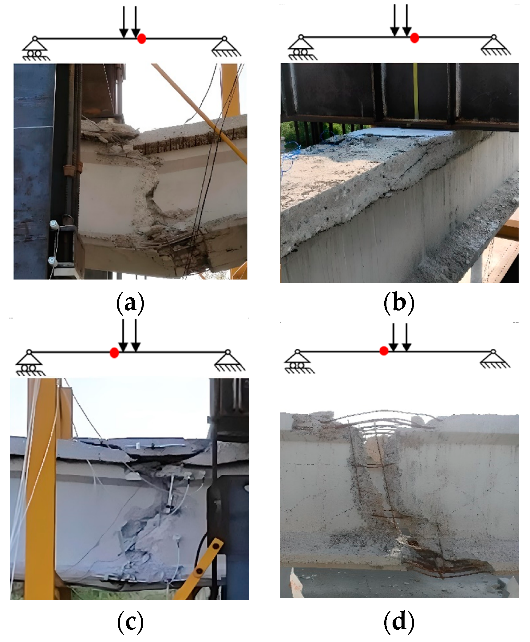
All girders collapsed in a non-ductile mode with a bending failure mechanism due to concrete crushing in the top compression zone. Figure 11 shows the failure zone for all the tested girders in detail.
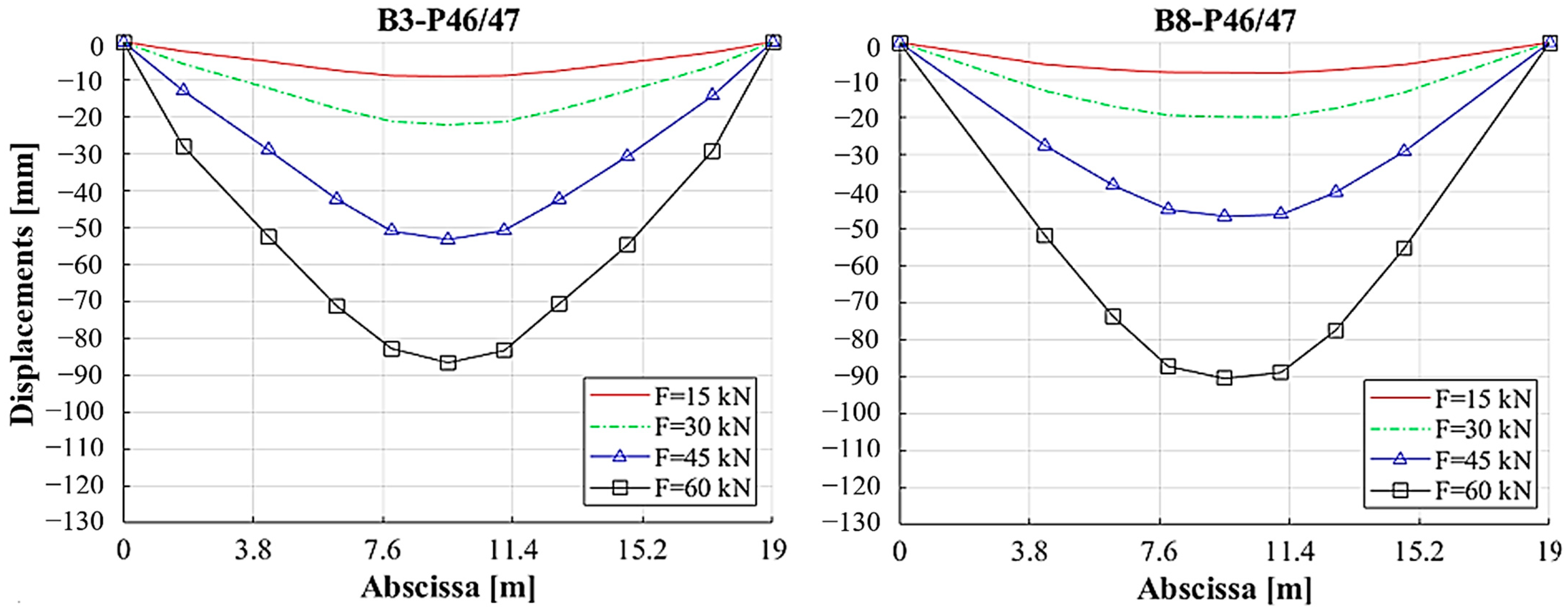
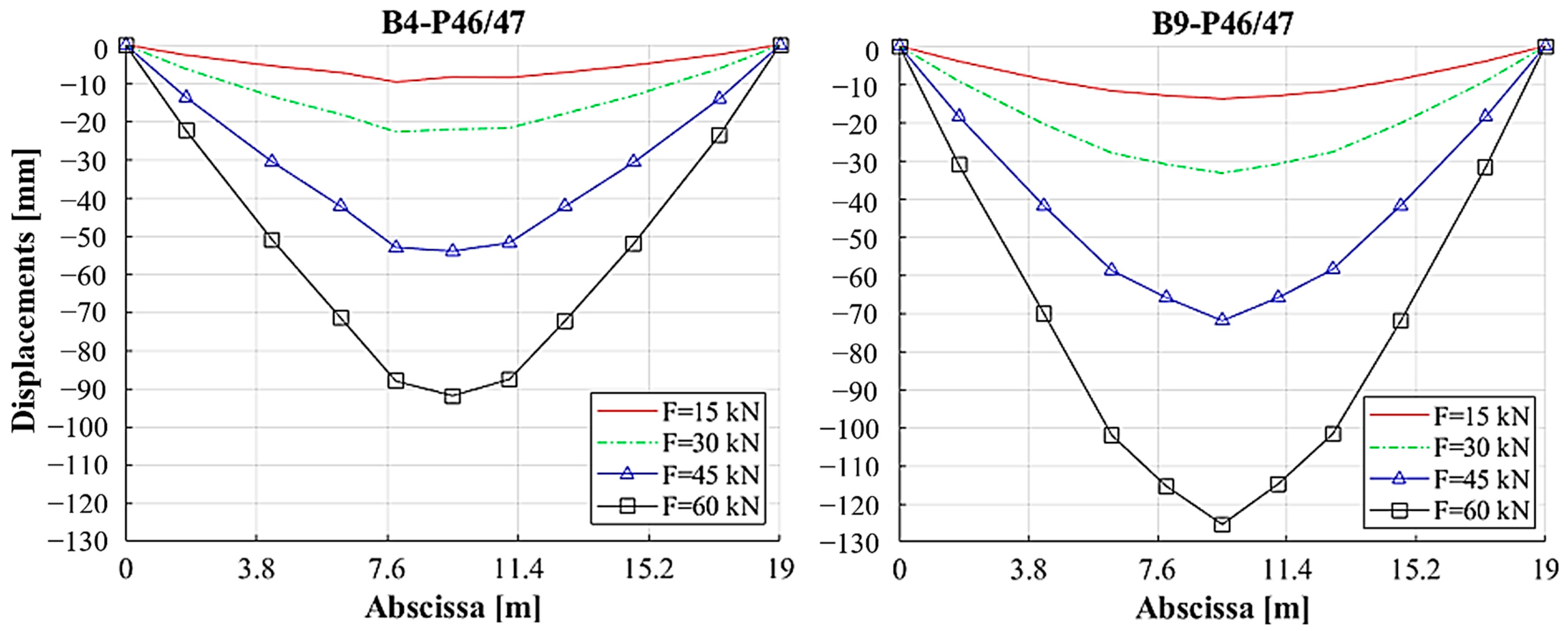
Figure 12 shows the deflection of each girder at the elastic stage (15 kN) and at the post cracked phases (30, 45 and 60 kN). For girders tested with two loading phases, the load at 60 kN refers to the second loading phase. The deflection was measured in the position of sensors from D01 to D09, according to the layout reported in Figure 9. As expected, the girder B9-P47/46, from which the cast in situ slab was removed, experienced a higher deflection due to a reduced flexural stiffness compared to the other girders. The deflections of the first three beams are similar for low load levels and become slightly different with increasing load.
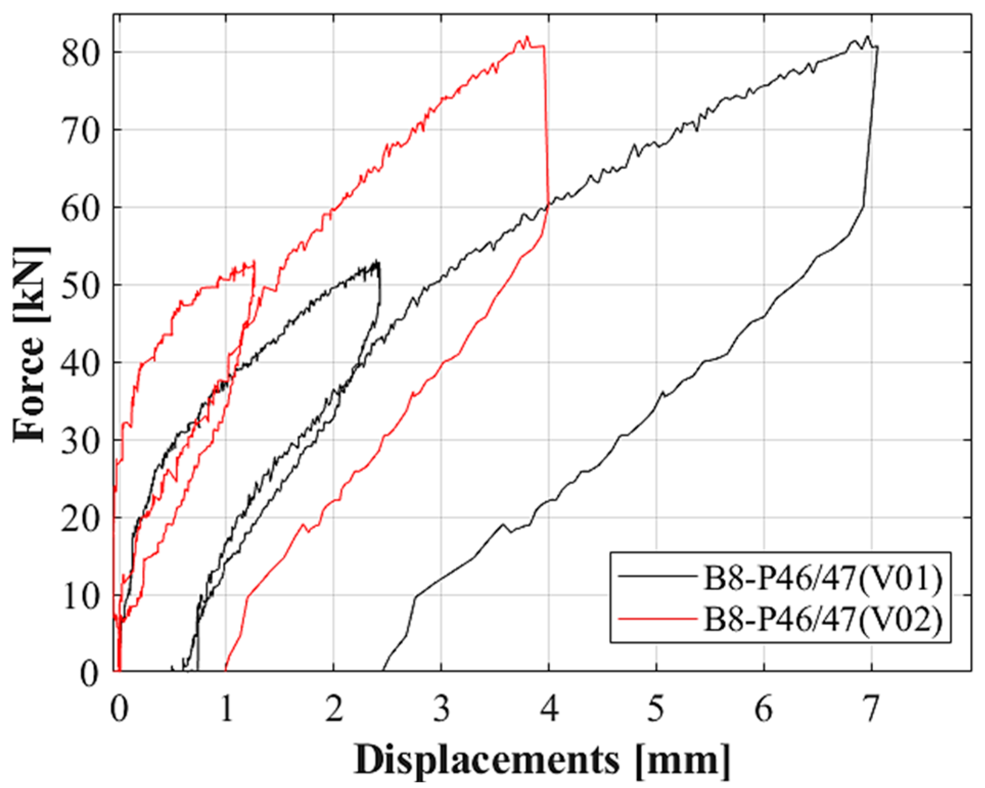
In order to remove vertical displacements from the deflection of the beams due to support settlement, transducers were placed in the support zone (devices V01 and V02 in Figure 9). During the load tests, not relevant settlements were measured at the support level, but their values were taken into account. As an example, the vertical displacements recorded for the B8-P47/46 beam are reported in Figure 13.

4.2. Cracking

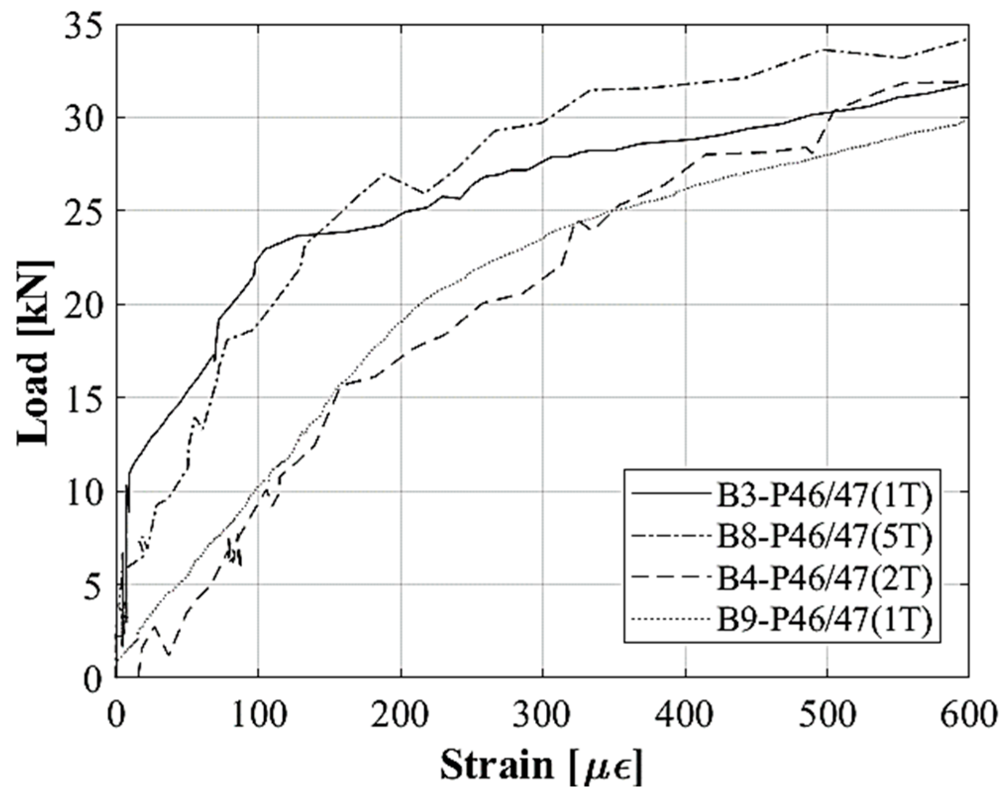
The first cracking load was estimated from the load–strain curve recorded by the LVDTs placed at the bottom flange of the PC specimens in the zone of tension. Figure 14 shows the plot of load versus tensile strain, regarding LVDTs, which recorded the minimum cracking load. To highlight the variation in the slope of the curves, a diagram up to 35 kN is shown. For the B3-P47/46, B8-P47/46, B4-P47/46 and B9-P47/46 beams, cracks began to open at an estimated applied load of 23 kN, 25 kN, 16 kN and 20 kN, respectively.
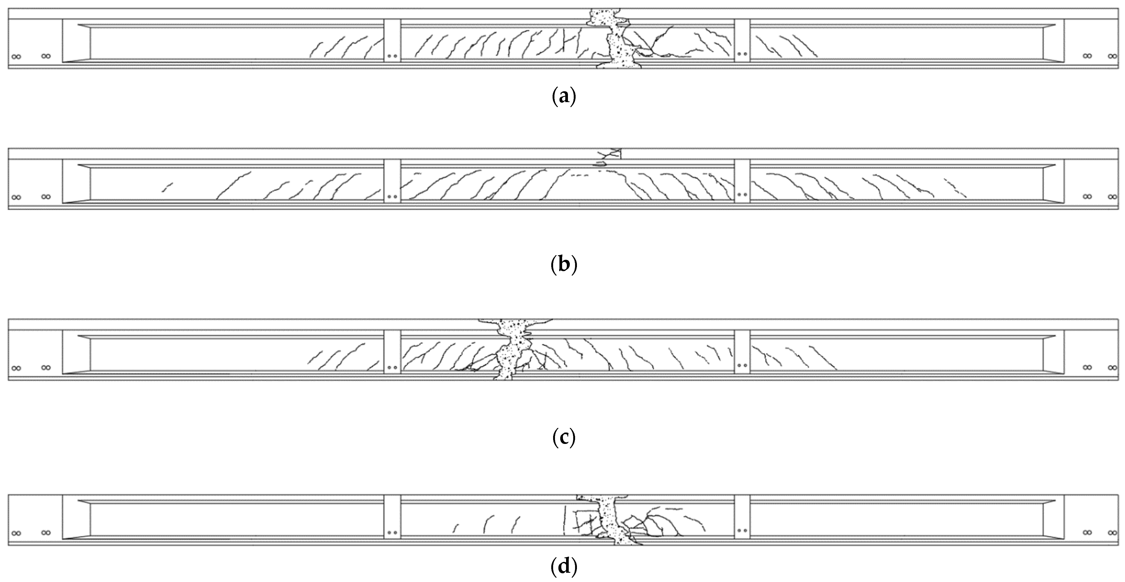
It can be observed that each curve starts with a linear trend. Once the applied load is sufficient to cause cracking, the nonlinearity begins and a change in the slope occurs. Figure 15 shows the mapping of the crack pattern recorded at the end of the load tests using markers by manual procedure and then reported in digital format. Typical flexural cracks were detected around the loading zone at the midspan in the region under the transverse steel beams. Cracks formed outside the midspan region present an influence of the shear effect and reveal an inclination toward the loading area. The top region of all the girders shows the crushing of the concrete in compression, which led to the failure. The subsequent collapse involved the whole section as a rigid rotation between two segments of the beam when the applied loading force was not promptly released.

4.3. Decompression Load

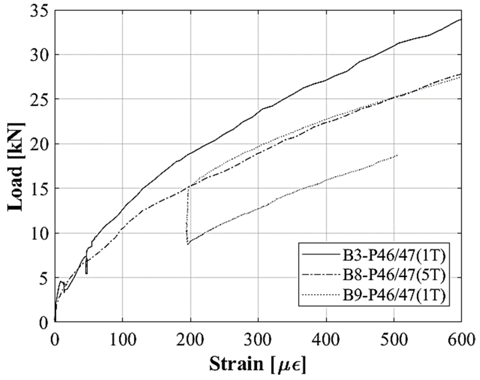
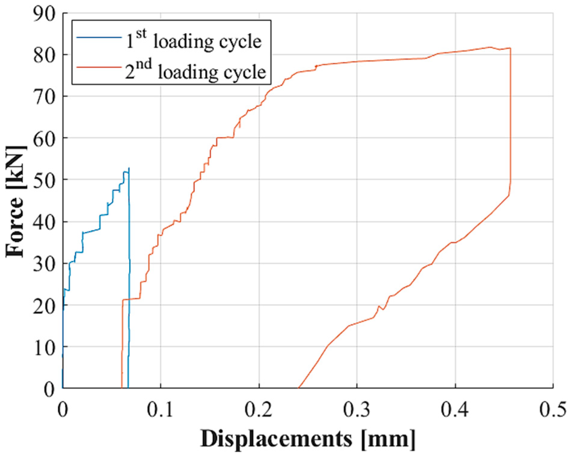
As mentioned in Section 2.3, the decompression load can be used to estimate the prestress loss. Figure 16 shows the load versus strain for the analysis of crack reopening recorded for specimens loaded in the two phases. During reloading, cracks remain closed due to the prestressing force and only elastic strains are recorded. Once the applied load is sufficient to reopen the cracks, it was no longer transferred across them and a sharp change in slope was observed. The transition from compression to the tension state of orthogonal stress to the crack profile at the bottom flange of the beam can be estimated independently from the tensile strength of concrete and, therefore, can be a more reliable base to estimate the prestressing force. The diagram highlights a change in slope at 16 kN, 11 kN and 15 kN for the B3-P47/46, B8-P47/46 and B9-P47/46 beams, respectively. For the B9-P46/47 curve, the unloading phase can be observed, followed by reloading starting from 9 kN.

4.4. Compressive Strains

The compressive strain recorded in the top region of the girders is a parameter to study the distribution of strain along the cross-section during the load test and can provide key information on the structural response of the girders during the load test. The continuous strain measurements obtained for the B3-P47/46, B8-P47/46 and B9-P47/46 beams in the top compressed region are presented in Figure 17. The maximum compressive strain recorded at the half of the thickness of the cast in situ slab of the composite sections of B3-P47/46 and B8-P47/46 was −3.6‰ and −3.8‰, respectively. For the B9-P47/46 beam, the compressive strain recorded at the half of the thickness of the top flange at failure load was −1.7‰.
For the B8-P47/46 curve, an anomalous behaviour at the beginning of the test was recorded, characterized by a constant strain value with increasing load, and probably linked to a locking of the LVDT supporting frame.

4.5. Strand Slip

The prestressing force in PC structures is transferred from strand to the concrete due to bond at the strand–concrete interface. If the bond strength degrades over the years, the transfer of effective prestress is affected. In order to evaluate the possible slip of prestressing strands during the load test, the relative displacement between concrete at the end of the beam and the strand unbonded for the first 3 m with the sensors in positions STR-01 and STR-02 (Figure 9) was measured. During the load tests, no significant slipping of the strands was recorded. As an example, the displacements recorded by the sensor STR-02 of the B8-P47/46 beam are reported in Figure 18. The slipping of the strand can be observed starting from a load of 24.05 kN. The maximum value of the slip recorded at failure load is 0.46 mm.

4.6. Shear Strains

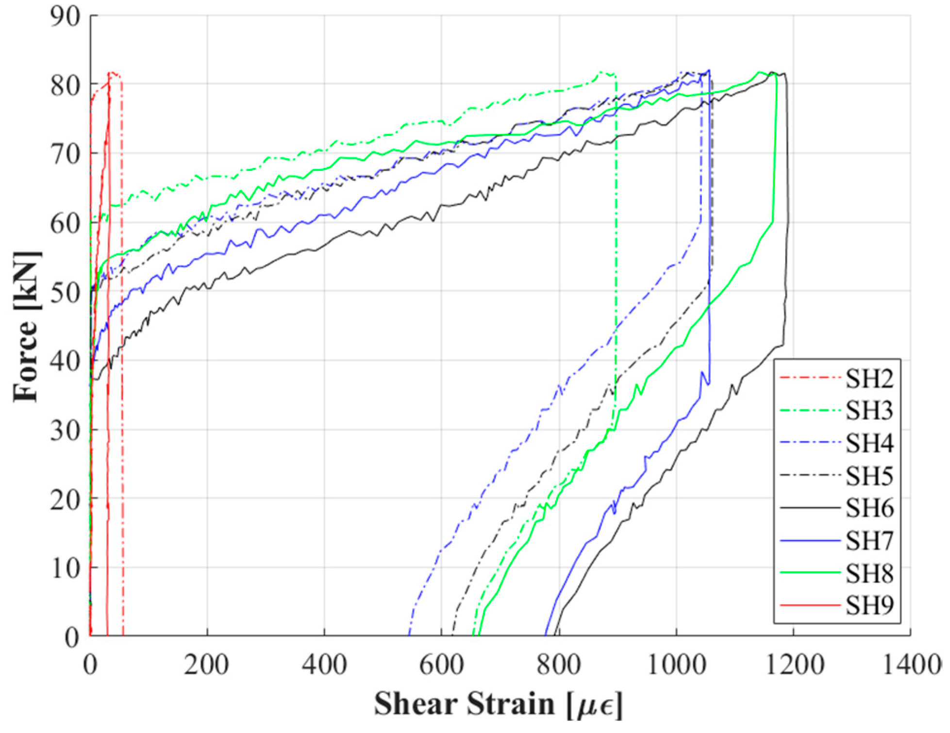
One of the aims of the experimental research is to study the structural behavior up to failure, paying particular attention to the bending and shear resistance mechanism. In the first group of specimens reported in the present paper, a flexural failure was expected, with a mechanical test designed accordingly. Nevertheless, multiple schemes of devices were designed and installed to record shear strains in relevant positions. Figure 19 shows the measurements recorded by the transducers’ reading tensile effect belonging to the B8-P47/46 beam. The dashed–dotted lines refer to the sensors installed on the left side of the beam (position A in Figure 9); the solid lines represent the strain recorded on the right side (position B in Figure 9). A correspondence between the dashed and solid lines can be observed, with the exception of SH6 and SH8, which show a slight increase on the right side compared to the left one. Furthermore, a reduction in strain is recorded by moving from the midspan to the support zone.
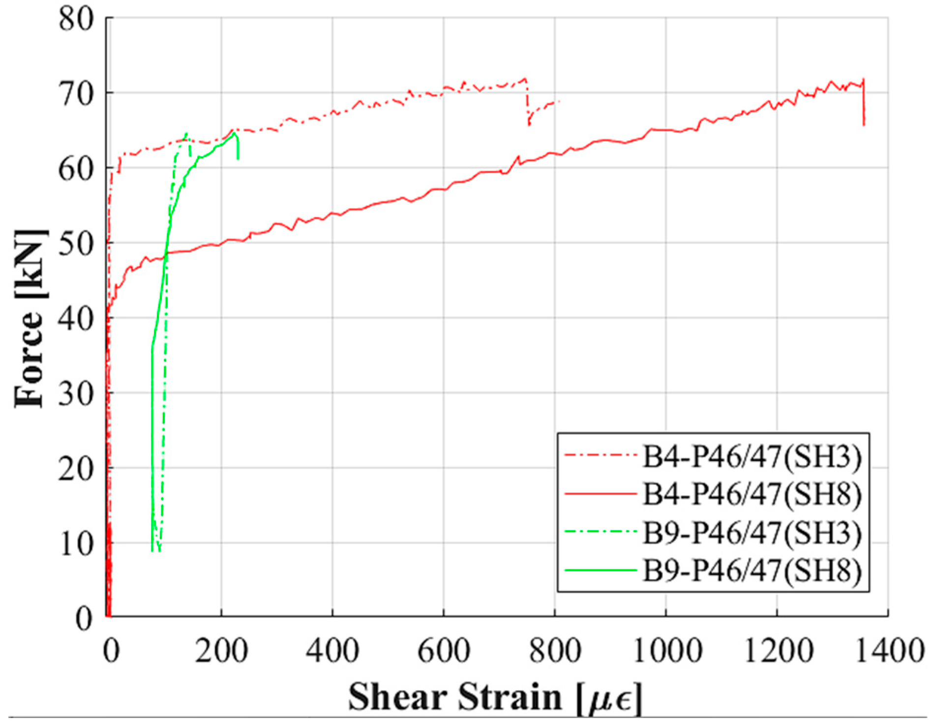
Figure 20 shows a comparison of the tensile shear strains at positions SH3 (A) and SH8 (B) of B4-P47/46 with the cast in situ slab and the B9-P47/46 beam without the cast in situ slab. Lower shear strains are reported for the B9-P47/46 specimen compared to B4-P47/46; this could be due to the different resistance mechanism when approaching the maximum load.
These results are in line with the crack pattern recorded after the load tests shown in Figure 15. Indeed, the beam B4-P47/46 shows both flexural and shear cracks, whereas the beam B9-P47/46 reveals only few vertical cracks typical of a bending failure mechanism.

5. Discussion

The girders of the C.so Grosseto Viaduct studied in the present work have 50 years of service life in an urban environment and, consequently, have experienced all the aforementioned deterioration causes affecting this structural typology. The results reported in this paper concern the tests performed on the first group of girders and aim at characterizing their structural conditions up to failure. In particular, the tests were designed to investigate their flexural capacity response adopting a three-point bending test scheme. The choice of the test setup considered the presence of the damages induced during the dismantling operations. The girders were selected having damages located away from the most stressed area and most prone to experience rupture. The damage due to corrosion noticed at the edges of the girders was considered not to influence the outcome of the experimental tests.
The material properties obtained from the design documentation and laboratory tests performed at the time of construction were reported, such as the strengths of precast concrete, cast in situ slab and prestressing steel. A noticeable difference in terms of compressive strengths with the current material characterization were found. The results obtained for the samples extracted from both the slab and the beams show a resistance of 40% lower than what was reported on the tests performed at the time of construction. Given the importance of these parameters to correctly interpret the static tests results, the material characterization study will be extended, paying particular attention to all the phases of sampling and extraction of the cores. The results of the test on steel confirm what was reported in the design project. The static tests conducted on the three complete girders showed a similar behavior in terms of deflection, maximum capacity and failure mechanism.
The maximum midspan deflections up to collapse recorded for all the tests reveal a ratio less than 1/100 of the span that is typically addressed to PC beams. The crushing of the cast in situ concrete slab for the B3 and B8 and B4-P47/46 girders and of the top flange of the B9-P47/46 girder was reported, highlighting a non-ductile rupture behavior. The girder B4-P47/46 shows a double peak revealing an initial crushing of the cast in situ slab, followed by the crushing of the top slab of the PC beam at a lower load that determined the global collapse (Figure 11c). In all the four tests, the crush of the slab occurred close to the loading system and not at the maximum bending moment section, probably due to the confining action exerted by the transverse steel beams; indeed, a diagonal crack on the most compressed zone departed from the bottom flange of the same steel beam, as can be observed in Figure 11. In Figure 10, the non-ductile performance of the girders is apparent, with no evidence of yielding of the prestressing steel. The girders tested, after adopting the two-loading phases, did not show residual damages such as visible cracks at the end of the unloading, except for a residual deflection due to non-recoverable deformations. Moreover, no significant difference in terms of maximum loads was registered. On the other hand, the two-phase tests adopted for B3-P47/46 and B8-P47/46 and also for the B9-P47/46 girders allowed us to evaluate the decompression loads disregarding the value of the tensile strength of concrete. The crack opening values reported in Section 4.2 can be compared to the results of specific tests on strands and concrete in order to estimate the prestressing losses more accurately. For reinforced concrete beams, cracks directly affect the moment of inertia of the cross-section and the flexural stiffness decreases accordingly. For PC beams, as highlighted by the load–displacement curve of the two-phase load tests, there are no evident signs of stiffness reduction in the second loading phase, due to the beneficial effect provided by prestressing. Referring to the first loading phase, a lower flexural stiffness was observed for the girder B9-P47/46, due to the removal of the cast in situ slab. In addition, a residual deflection can be seen for specimens loaded with two loading phases due to non-recoverable deformation also caused by the first load phase at a level higher than the cracking load. At collapse, no signs of corrosion were detected on the exposed prestressing strands, confirming the good protection exerted from the concrete cover at the time of the test. The peak load registered for the B9-P47/46 girder was 20% lower than the maximum load obtained for girders with cast in situ slabs, probably evidencing the limited contribution of the cast in situ slab.
Cracking after loading test had a similar flexural pattern with vertical cracks starting at a lower flange and turning horizontally, especially for girder B8-P47/46, which also reached the highest value of load; moreover, in B8-P47/46, a larger portion of the beam was involved by cracks even closer to the support zones. The moving of the three couples of LVDT for shear strain evaluation toward the transverse beam location with respect to the first setup reported in Figure 9 was intended to intercept these cracks. A different pattern with few cracks, mainly in the vertical direction, is reported for B9-P47/46, the girder without the cast in situ slab, both in terms of extension (zone within the two transverse beams) and number (few concentrated cracks), highlighting an altered resistance mechanism with respect to previous girders, with a lowering of the top chord compressed member.
The first cracking estimated by the LVDTs placed in the bottom flange showed some variability among the girders. It is important to observe that the beam B9-P47/46 shows a value of 20 kN, which is also the result of the removal of the cast in situ slab for both its absence in the resistance mechanism and its weight in terms of loading. This first cracking could be also deeply affected by the actual residual prestressing and, in turn, it can be a parameter for its evaluation. The compressive strains reveal a large deformation at the level of the most compressed element of the girder (the cast in situ slab or the top flange) and the analytical evaluation of the neutral axis position allows us to infer that the maximum strain at the top fiber was obviously larger. No valuable slip was measured in the experiments between the concrete at the edges of the girders and the selected unbonded strands, and this reveals an efficient stress transmission and a proper transmission length within this loading scheme. Other strain measurements confirm the outcomes of crack formation and the resisting mechanism evidenced during the loading test up to collapse.

6. Conclusions

In this paper, the first results of the large-scale experimental tests of the BRIDGE|50 research project were reported. This research project proposes an extensive experimental study for the assessment of the performance of existing PC bridges. A detailed description of the design and execution of the experimental program was reported, including load test scheme and sensor devices’ layout. The results of the first group of four PC girders are presented and discussed. Based on the results of the flexural tests conducted with a three-point bending test scheme on a large facility for real-scale mechanical experiments, the influence of the material and structural characteristics of the girders was highlighted. In particular, a brittle behavior was detected, with the failure firstly located at the most compressed zone subjected to bending, highlighting the cast in situ slab as a weak structural component. An overestimation of the concrete strength assumptions was found within the design documentation for both the PC beam and cast in situ slab. Comparing these values with the outcomes provided by the destructive laboratory tests, a reduction of about 46% and 33% was recorded for the cast in situ slab and PC beam, respectively. Additional activities will be conducted to increase data on the mechanical properties of concrete and steel with destructive tests in addition to specific research aimed at estimating the effective prestress force with concrete relief test and strand cutting procedures on the tested girders. Given the healthy structural condition of this first group of PC beams, a uniform ultimate capacity was found among them, without any dependence on particular deterioration mechanisms.
The results collected from this experimental study could be of extreme interest to evaluate the specimen characteristics and calibrate numerical models for the safety assessment of existing structures. Moreover, a proper numerical model fitting the results, according to the outcome of the dynamic tests, will be representative of the in-service health condition of the C.so Grosseto viaduct. The next large-scale tests will analyze different shear span lengths to study the bending moment interaction resistance mechanism in addition to the shear failure mechanism for undamaged and damaged girders. Furthermore, specific mechanical tests for pier caps available for the BRIDGE|50 research project will be also planned and performed.

Author Contributions

Conceptualization, F.T., D.S., A.Q., F.B., G.R. and B.C.; methodology, F.T., D.S., A.Q. and F.B.; investigation, P.S., F.T., D.S., A.Q. and M.A.; resources, P.S., F.T., D.S., A.Q. and F.B.; data curation, P.S. and A.Q.; writing—original draft preparation, P.S., D.S. and A.Q.; writing—review and editing, F.T., F.B., M.A. and B.C.; supervision, F.T.; project administration, F.T. and F.B.; funding acquisition, F.T., D.S. and B.C. All authors have read and agreed to the published version of the manuscript.

Funding

This research received no external funding.

Institutional Review Board Statement

Not applicable.

Informed Consent Statement

Not applicable.

Data Availability Statement

Not applicable.

Acknowledgments

BRIDGE|50 is a research project based on a research agreement among universities, public authorities and private companies. Members of the Management Committee: S.C.R. Piemonte (President), Politecnico di Milano (Scientific Coordinator), Politecnico di Torino (Scientific Responsible of the Experimental Activities), Lombardi Engineering (Secretary), Piedmont Region, City of Turin, Metropolitan City of Turin, TNE Torino Nuova Economia, ATI Itinera & C.M.B., ATI Despe & Perino Piero, Quaranta Group. BRIDGE|50 website: http://www.bridge50.org.

Conflicts of Interest

The authors declare no conflict of interest.

References

  1. Biondini, F.; Frangopol, D.M. Life-Cycle Design, Assessment and Maintenance of Structures and Infrastructure Systems; American Society of Civil Engineers (ASCE): Reston, VA, USA, 2019. [Google Scholar] [CrossRef]
  2. Biondini, F.; Frangopol, D.M. Life-cycle performance of deteriorating structural systems under uncertainty: Review. J. Struct. Eng. 2016, 142, 1–17. [Google Scholar] [CrossRef]
  3. Papè, T.M.; Melchers, R.E. The effects of corrosion on 45-year-old pre-stressed concrete bridge beams. Struct. Infrastruct. Eng. 2011, 7, 101–108. [Google Scholar] [CrossRef]
  4. Jeon, C.H.; Sim, C.; Shim, C.S. The effect of wire rupture on flexural behavior of 45-year-old post-tensioned concrete bridge girders. Eng. Struct. 2021, 245, 112842. [Google Scholar] [CrossRef]
  5. Eder, R.W.; Miller, R.A.; Baseheart, T.M.; Swanson, J.A. Testing of two 50-year-old precast post-tensioned concrete bridge girders. PCI J. 2005, 50, 90–95. [Google Scholar] [CrossRef]
  6. Lundqvist, P.; Riihimäki, J. Testing of five 30-year-old prestressed concrete beams. PCI J. 2010, 55, 50–58. [Google Scholar] [CrossRef]
  7. Taffe, A.; Hillemeier, B.; Walther, A. Condition Assessment of a 45-year-old prestressed concrete bridge using NDT and verification of the results. Struct. Mater. Technol. 2010. [Google Scholar] [CrossRef]
  8. Shenoy, C.V.; Frantz, G.C. Structural Tests of 27-Year-Old Prestressed Concrete Bridge Beams. PCI J. 1991, 36, 80–90. [Google Scholar] [CrossRef]
  9. Zwicky, D.L. Structural evaluation of 30-year-old prestressed concrete girders. In Proceedings of the 3rd International PhD Symposium in Civil Engineering, Vienna, Austria, 5–7 October 2000. [Google Scholar]
  10. Dasar, A.; Irmawaty, R.; Hamada, H.; Sagawa, Y.; Yamamoto, D. Prestress Loss and Bending Capacity of Pre-cracked 40 Year-Old PC Beams Exposed to Marine Environment. In Proceedings of the 3rd International Conference on Civil and Environmental Engineering for Sustainability (IConCEES 2015), Melaka, Malaysia, 1–2 December 2015. [Google Scholar] [CrossRef] [Green Version]
  11. Kramer, W.; Martin, W.; Viljoen, H. Demolition of Old Oak Bridge B4113: Condition of a 54-year old prestressed concrete bridge. In Proceedings of the International Conference on Concrete Repair, Rehabilitation and Retrofitting (ICCRRR 2018), Cape Town, South Africa, 19–21 November 2018. [Google Scholar] [CrossRef]
  12. Azizinamini, V.; Keeler, B.J.; Rohde, J.; Mehrabi, A.B. Application of a New Nondestructive Evaluation Technique to a 25-Year-Old Prestressed Concrete Girder. PCI J. 1996, 41, 82–95. [Google Scholar] [CrossRef]
  13. Halsey, J.T.; Miller, R. Destructive Testing of Two Forty-Year-Old Prestressed Concrete Bridge Beams. PCI J. 1996, 41, 84–93. [Google Scholar] [CrossRef]
  14. Jin-liang, L.; Yan-min, J. Destructive testing of twenty-year-old prestressed concrete bridge beams in freezing-thawing region. Civ. Eng. J. 2019, 3. [Google Scholar] [CrossRef]
  15. Rao, C.; Frantz, G.C. Fatigue tests of 17-year-old prestressed concrete bridge box beams. PCI J. 1996, 41, 74–83. [Google Scholar] [CrossRef]
  16. Recupero, A.; Spinella, N. Experimental tests on corroded prestressed concrete beams subjected to transverse load. Struct. Concr. 2019, 20, 2220–2229. [Google Scholar] [CrossRef]
  17. Pessiki, S.; Kaczinski, M.; Wescott, H.H. Evaluation of Effective Prestress Force in 28-Year-Old Prestressed Concrete Bridge Beams. PCI J. 1996, 41, 78–89. [Google Scholar] [CrossRef]
  18. Botte, W.; Vereecken, E.; Taerwe, L.; Caspeele, R. Assessment of posttensioned concrete beams from the 1940s: Large-scale load testing, numerical analysis and Bayesian assessment of prestressing losses. Struct. Concr. 2021, 22, 1500–1522. [Google Scholar] [CrossRef]
  19. Shu, J.; Bagge, N.; Nilimaa, J. Field Destructive Testing of a Reinforced Concrete Bridge Deck Slab. J. Bridge Eng. 2020, 25, 04020067. [Google Scholar] [CrossRef]
  20. Pepe, T.M.; Melchers, R.E. Performance of 45-year-old corroded prestressed concrete beams. Proc. Inst. Civ. Eng. Struct. Build. 2013, 166, 547–559. [Google Scholar] [CrossRef]
  21. Savino, P.; Anghileri, M.; Chiara, M.; Salza, B.; Quaranta, L. Corso Grosseto viaduct: Historical and technical overview. In Proceedings of the Tenth International Conference on Bridge Maintenance, Safety and Management (IABMAS 2020), Sapporo, Japan, 28 June–2 July 2020. [Google Scholar]
  22. Biondini, F.; Manto, S.; Beltrami, C.; Tondolo, F.; Chiara, M.; Salza, B.; Tizzani, M.; Chiaia, B.; Lencioni, A.; Panseri, L.; et al. BRIDGE|50 research project: Residual structural performance of a 50-year-old bridge. In Proceedings of the 10th International Conference on Bridge Maintenaince, Safety and Management (IABMAS 2020), Sapporo, Japan, 28 June–2 July 2020. [Google Scholar]
  23. Biondini, F.; Tondolo, F.; Manto, S.; Beltrami, C.; Chiara, M.; Salza, B.; Tizzani, M.; Chiaia, B.; Lencioni, A.; Panseri, L.; et al. Residual Structural Performance of Existing PC Bridges: Recent Advances of the BRIDGE|50 Research Project. In Proceedings of the First Conference of the European Association on Quality Control of Bridges and Structures (EUROSTRUCT 2021), Padua, Italy, 29 August–1 September 2021. [Google Scholar]
  24. Biondini, F.; Tondolo, F.; Manto, S.; Beltrami, C.; Chiara, M.; Salza, B.; Tizzani, M.; Chiaia, B.; Lencioni, A.; Panseri, L.; et al. Residual Structural Performance of a 50-Year-Old Viaduct in Italy—The BRIDGE|50 Project. In Bridge Maintenance, Safety, Management, Life-Cycle Sustainability and Innovations; CRC Press: Boca Raton, FL, USA, 2021. [Google Scholar]
  25. Anghileri, M.; Biondini, F.; Rosati, G.; Savino, P.; Tondolo, F.; Sabia, D.; Manto, S.; Nivriera, M.; Trincianti, C.; Ventura, D.; et al. Deconstruction of the Corso Grosseto viaduct and setup of a testing site for full scale load tests. In Proceedings of the Tenth International Conference on Bridge Maintenance, Safety and Management (IABMAS 2020), Sapporo, Japan, 28 June–2 July 2020. [Google Scholar]
  26. Ing, Massaro. Progetto esecutivo—Interscambio stradale Largo Grosseto; Repository of Turin Municipality; Ufficio Tecnico Lavori Pubblici Città di Torino—Ripartizione IV: Turin, Italy, 1970. [Google Scholar]
  27. Beltrami, C.; Bianchi, S.; Cervio, M.; Anghileri, M.; Felicetti, R.; Quattrone, A.; Chiara, M.; Salza, B.; Masala, D. Bridge visual inspections: Experience of local authorities and the case study of the Corso Grosseto viaduct. In Proceedings of the Tenth International Conference on Bridge Maintenance, Safety and Management (IABMAS 2020), Sapporo, Japan, 28 June–2 July 2020. [Google Scholar]
  28. Sabia, D.; Quattrone, A.; Tondolo, F.; Savino, P. Dynamic identification of damaged PC bridge beams. In Proceedings of the First Conference of the European Association on Quality Control of Bridges and Structures (EUROSTRUCT 2021), Padua, Italy, 29 August–1 September 2021. [Google Scholar]
  29. Sabia, D.; Quattrone, A.; Tondolo, F.; Savino, P. Experimental evaluation of the effect of controlled damages on the dynamic response of PC bridge beams. In Proceedings of the 11th International Conference on Bridge Maintenance, Safety and Management (IABMAS 2022), Barcelona, Spain, 11–15 July 2022. [Google Scholar]
  30. Anghileri, M.; Savino, P.; Capacci, L.; Bianchi, S.; Rosati, G.; Tondolo, F.; Biondini, F. Non-destructive testing and model validation of corroded PC bridge deck beams. In Proceedings of the First Conference of the European Association on Quality Control of Bridges and Structures (EUROSTRUCT 2021), Padua, Italy, 29 August–1 September 2021. [Google Scholar]
  31. Tondolo, F.; Biondini, F.; Sabia, D.; Rosati, G.; Chiaia, B.; Quattrone, A.; Savino, P.; Anghileri, M. Experimental program and full-scale load tests on PC deck beams. In Proceedings of the First Conference of the European Association on Quality Control of Bridges and Structures (EUROSTRUCT 2021), Padua, Italy, 29 August–1 September 2021. [Google Scholar]
  32. Tondolo, F.; Sabia, D.; Chiaia, B.; Quattrone, A.; Biondini, F.; Rosati, G.; Anghileri, M. Full-scale testing and analysis of 50-year old prestressed concrete bridge girders. In Proceedings of the 11th International Conference on Bridge Maintenance, Safety and Management (IABMAS 2022), Barcelona, Spain, 11–15 July 2022. [Google Scholar]
  33. Carsana, M.; Biondini, F.; Redaelli, E.; Valoti, D.O. On-site corrosion characterization of 50-year-old PC deck beams. In Proceedings of the First Conference of the European Association on Quality Control of Bridges and Structures (EUROSTRUCT 2021), Padua, Italy, 29 August–1 September 2021. [Google Scholar]
  34. Carsana, M.; Valoti, D.O.; Redaelli, E.; Biondini, F. Corrosion assessment of 50-year-old PC deck beams. In Proceedings of the 11th International Conference on Bridge Maintenance, Safety and Management (IABMAS 2022), Barcelona, Spain, 11–15 July 2022. [Google Scholar]
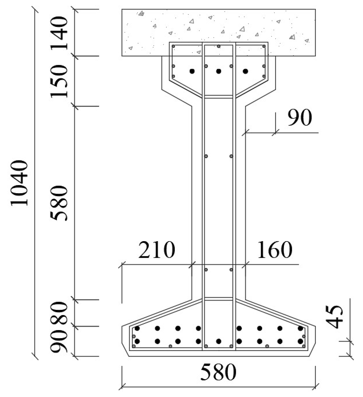
Figure 1. Historical view of the Corso Grosseto viaduct.
Applsci 13 00834 g001
Figure 2. (a)Top view; (b) cross-section of the PC deck (in meters).
Applsci 13 00834 g002
Figure 3. I-beam cross-section (in mm).
Applsci 13 00834 g003
Figure 4. Deconstruction phases: (a) cutting; (b) drilling; (c) sling ropes; (d) lifting; (e) moving; (f) testing site setup.
Applsci 13 00834 g004
Figure 5. Typical damage due to lifting operations: (a) damage at 4 m and (b) damage at 15 m from the beginning of the PC girder.
Applsci 13 00834 g005
Figure 6. Cracks on the end of the (a) B3-P47/46 and (b) B4-P47/46 beams.
Applsci 13 00834 g006
Figure 7. Technical drawing of the reaction steel frame in black, supporting frames in blue and loading frames in red (in cm).
Applsci 13 00834 g007
Figure 8. Three-point bending test configuration.
Applsci 13 00834 g008
Figure 9. Test setup and layout of the monitoring system installed on the PC girder during the load test (in cm).
Applsci 13 00834 g009
Figure 10. Load versus midspan deflection with dots located at the estimated first cracking and peak loads for each girder.
Applsci 13 00834 g010
Figure 11. Failure zone details for: (a) B3-P47/46, (b) B8-P47/46, (c) B4-P47/46, (d) B9-P47/46 and the corresponding position.
Applsci 13 00834 g011
Figure 12. Longitudinal deformed shape of girders at 15, 30, 45 and 60 kN.
Applsci 13 00834 g012aApplsci 13 00834 g012b
Figure 13. Vertical displacements of the support for the B8-P47/46 beam.
Applsci 13 00834 g013
Figure 14. Applied load versus tensile strain.
Applsci 13 00834 g014
Figure 15. Crack pattern after the load tests of the (a) B3, (b) B8, (c) B4 and (d) B9-P47/46 girders.
Applsci 13 00834 g015
Figure 16. Applied load versus crack reopening.
Applsci 13 00834 g016
Figure 17. Applied load versus top compressive strain.
Applsci 13 00834 g017
Figure 18. Force–strand slip curves for STR-02 of B8-P47/46.
Applsci 13 00834 g018
Figure 19. Tensile shear strain of the B8-P47/46 beam.
Applsci 13 00834 g019
Figure 20. Force–tensile shear strain for SH3 and SH8 for the B4-P47/46 and B9-P47/46 beams.
Applsci 13 00834 g020
Table 1. Load test protocol.
Load TestBeam CodeLoading PhasesConcrete Cross-Section
1B3-P47/462Composite
2B8-P47/462Composite
3B4-P47/461Composite
4B9-P47/462I-beam
Table 2. Material properties of the destructive tests.
LocationMaterialPropertyTestNo.UnitMean ValueStandard Deviation
SlabConcreteCompressive strengthCompression5MPa21.94.7
SlabConcreteTensile strengthIndirect tensile test2MPa2.40.9
GirderConcreteCompressive strengthCompression10MPa33.66.7
GirderConcreteTensile strengthIndirect tensile test9MPa3.40.5
GirderPrestressing steelYield strengthTensile8MPa1521.568.0
GirderPrestressing steelUltimate tensile strengthTensileMPa1763.460.1
GirderPrestressing steelElongation at maximum loadTensile%3.41.1
Table 3. Characteristics of the sensors’ layout.
ParametersSensorLocationNo.
DeflectionWire displ. transducerD04-063
DeflectionDispl. potentiometer transducerD01-03 D07-096
DisplacementLinear displ. transducerV01-02 H01-024
Strand slidingLinear displ. transducerSTR-01/022
Shear strainLinear variable displ. Transducer 11-1020
Bending strainLinear variable displ. Transducer 11T-7T
1C-4C
11
Bending strainStrain gauge2C-1T2
AccelerationAccelerometer1-10Z 10Y10
Acoustic emissionPZT transducerMidspan8
LoadLoad cellHydraulic jacks3
1 The measurement base of the LVDTs for shear and bending strain is 700 and 400 mm, respectively.
Disclaimer/Publisher’s Note: The statements, opinions and data contained in all publications are solely those of the individual author(s) and contributor(s) and not of MDPI and/or the editor(s). MDPI and/or the editor(s) disclaim responsibility for any injury to people or property resulting from any ideas, methods, instructions or products referred to in the content.