Article

Finite Element Modeling of the Fingers and Wrist Flexion/Extension Effect on Median Nerve Compression

1
Department of Computational Mathematics, Mechanics, and Biomechanics, Perm National Research Polytechnic University, 614990 Perm, Russia
2
Department of Neurology and Medical Genetics, Perm State Medical University, 614990 Perm, Russia
*
Author to whom correspondence should be addressed.
Appl. Sci. 2023, 13(2), 1219; https://doi.org/10.3390/app13021219
Submission received: 10 December 2022 / Revised: 7 January 2023 / Accepted: 12 January 2023 / Published: 16 January 2023
(This article belongs to the Special Issue Hand and Wrist Biomechanics)

Abstract

:
Carpal tunnel syndrome (CTS) is the most common pathology among disorders of the peripheral nervous system related to median nerve compression. To our knowledge, there are limited data on the effect of tendon movement on median nerve compression. This study focuses on the understanding of the carpal syndrome by simulating the impact of tendons movement caused by fingers flexion by Finite Element Analysis. Therefore, such modeling is the step toward the development of a personalized technique for value determining median nerve compression. Open-source MRI of the human right hand was used to build patient-specific phalanges of the fingers. Carpal tunnel soft tissues were considered as hyper-elastic materials, while bone structures were considered as elastic ones. The final finite-element model had 40 solid bodies which contacted the joint. Results were obtained for four cases of wrist movements: finger flexion, hand flexion/extension, and wrist extension with subsequent by finger flexion. Compression of the median nerve ranged from 129 Pa to 227 Pa. The results show that compression of the median nerve occurs faster during wrist flexion than during wrist extension or finger flexion. A decrease in compression during finger flexion was noticed with wrist extension followed by finger flexion.

1. Introduction

Carpal tunnel syndrome (CTS) is the most common pathology among disorder of the peripheral nervous system. The wrist loses sensory and motor functions resulting from the compression of the median nerve by nearby tissue [1,2]. There are several methods to diagnose CTS, including a combined method. Checking the electrical conductivity of the median nerve allows localization of the damaged nerve fibers [3]. Electrodes are attached to the wrist and an electrical impulse is applied, then the median nerve conductivity latency is measured. Imaging of the median nerve with MRI, CT and ultrasound is widely used in the diagnosis of carpal tunnel syndrome. No equipment is required for tests such as Tinel’s sign, Phalen’s test, Durkan’s test, and others, which involve performing physical movements that lead to pain in patients with carpal tunnel syndrome. The described diagnostic methods are known to give false positive results, and there is no gold standard method for diagnosing CTS [4]. None of these tests provide information about the main cause of compression. Pressure inside the carpal tunnel during finger and hand movements compresses the median nerve. To calculate this pressure, biomechanical modeling is necessary [5].
Guo et al. 2007 [6] showed morphological changes in the transverse carpal ligament using finite element modeling. The study included the carpal bones and the transverse carpal ligament, which were modeled by modulus of elasticity and Poisson’s ratio. Ko and Brown 2007 [7] analyzed the effect of fluid pressure inside the carpal tunnel using fluid–structural interaction. The results suggest that median nerve stresses due to direct structural contact are typically far higher than those from fluid pressure. Javanmardian and Haghpanahi 2010 [8] investigated the effect of damage on carpal ligaments and the movement of carpal bones by finite element analysis. Mouzakis et al. 2014 [9] assessed the impact of computer work on carpal tunnel syndrome. A finite element model including tendons, bones, skin, muscles, connective tissue, synovial tissue, ligaments and nerve was presented. The behavior of structures was described by Young’s modulus and Poisson’s ratio. Yao et al. 2018 [10] analyzed transverse carpal ligament tensile strain and carpal arch area by finite element modeling. Bones and transverse carpal ligament were modeled as elastic, and skin-fat and muscle were modeled as hyperelastic (Neo-Hookean strain energy potential). Oflaz and Gunal 2018 [11] clarified the loading pattern of each carpal bone during wrist movements. A finite element wrist model was designed using a three-dimensional reconstruction of computed tomographic images from the distal end of the radius and ulna to the proximal third of the metacarpals. Ligaments were placed as nonlinear spring models. Only bones and ligaments were included in the study. Perevoshchikova et al. 2021 [12] studied von Mises stress distribution in a novel multiphase bone-ligament-bone scaffold during physiological wrist movements. The study presented a patient-specific computational biomechanical evaluation of the effect of scaffold length, and positioning of the bone attachment sites. Scaphoid and lunate bones and scaffold were included in the calculation. Marqués et al. 2022 [13] investigated distal carpal row moves. A three-dimensional model of the proximal carpal row was created through DICOM images. Materials, contacts, and ligaments definitions were made via open-source software. Scapholunate interosseous ligament, cortical bone and cancelous bone were included in the study. Yokota et. el. 2019 [14] provided quantitative data on the mechanical effect of the pressure exerted by the abductor pollicis longus and extensor pollicis brevis muscles, with various wrist positions. The model was composed of four bones, one muscle, one tendon, and one tendon sheath. The humerus, radius, ulna, and bones of the hand were simplified to one solid body. Wei et al. 2020 [15] developed and validated a subject-specific framework for modeling the human hand. The geometries of the phalanges, carpal bones, wrist bones, ligaments, tendons, subcutaneous tissue and skin were all included. Tendons, ligaments and muscles were modeled as forces of a specific subject captured from the in-vivo grasping tests. Contact pressure with cylindrical, spherical and precision grasping were predicted by calculation and compared to the experimental data.
To our knowledge, there are limited data on the effect of tendon movement on median nerve compression as well as direct tendon modeling. Nine tendons pass through the carpal tunnel in close proximity to the median nerve and connect the flexor muscles and phalanx. These tendons are under load with any fingers or hand movement. For example, writing, keyboard typing, driving a car, sporting, playing music instruments, or just eating with a spoon.
This study attempts to contribute to the understanding of the carpal syndrome by direct tendon geometry modeling, and simulating the impact of tendon movement caused by fingers flexion, with the help of finite-element modeling. Such modeling is a step toward the development of a personalized technique for determining median nerve compression.

2. Materials and Methods

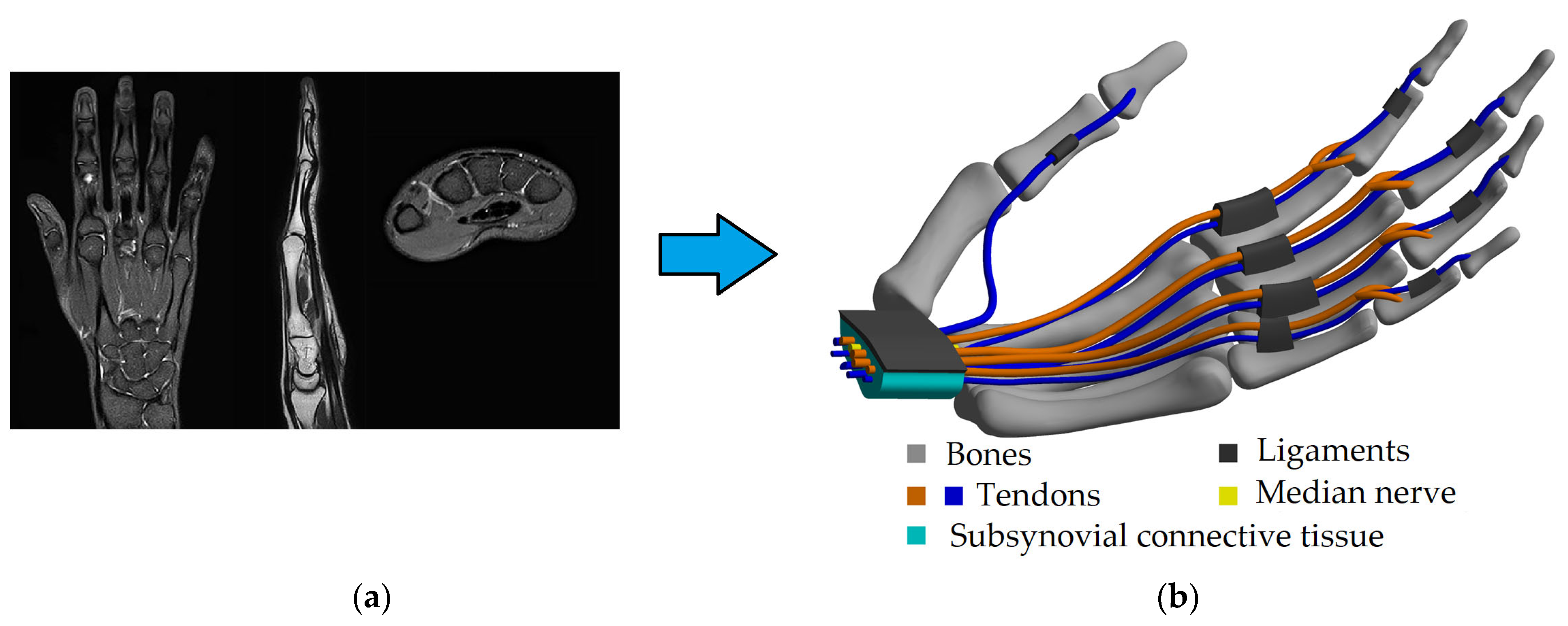
2.1. Geometry Modeling

Open-source MRI of the human left hand was used to build patient-specific [7] phalanges of the fingers and carpal bones (Figure 1). The magnetic resonance images were segmented and processed using open-source software. A three-dimensional model was designed. Soft tissues were obtained manually based on the characteristic geometric dimensions taken from MRI. Flexor digitorum deep, flexor digit superficial, annular ligaments, median nerve, subsynovial connective tissue (SSCT) within the carpal tunnel and transverse ligament were included in the model (Figure 1). The geometry of the carpal bones was simplified to allow filling the carpal canal with connective tissue, but the overall dimensions remained as the originals. The three-dimensional carpal tunnel had a 22.5 mm major diameter, an 8.9 mm minor diameter, and was 20 mm in length. The actual carpal bones geometry has a low effect on median nerve compression and tendon motion as they are essentially the distal (far from the center of the body) border of the carpal tunnel.

2.2. Mechanical Properties

Carpal tunnel soft tissues have hyper-elastic behavior [16]. The transverse carpal ligament, flexor tendons, median nerve, SSCT were assigned a first-order Ogden [17] hyperelastic material property definition according to previous studies [18,19,20,21,22,23,24]. Strain energy W is expressed as a function of the principal stretches λi, with material coefficients μ and α (Table 1).
W ( λ 1 , λ 2 , λ 3 ) = 2 μ α 2 ( λ 1 α + λ 2 α + λ 3 α 3 )
In this equation, μ is related to material behavior in the low-strain region, while α is related to the high-strain region of the stress/strain curve. Carpal bones and phalanges are tougher compared to other tissues, and were assigned as linear elastic with E and ν [25] (Table 1).

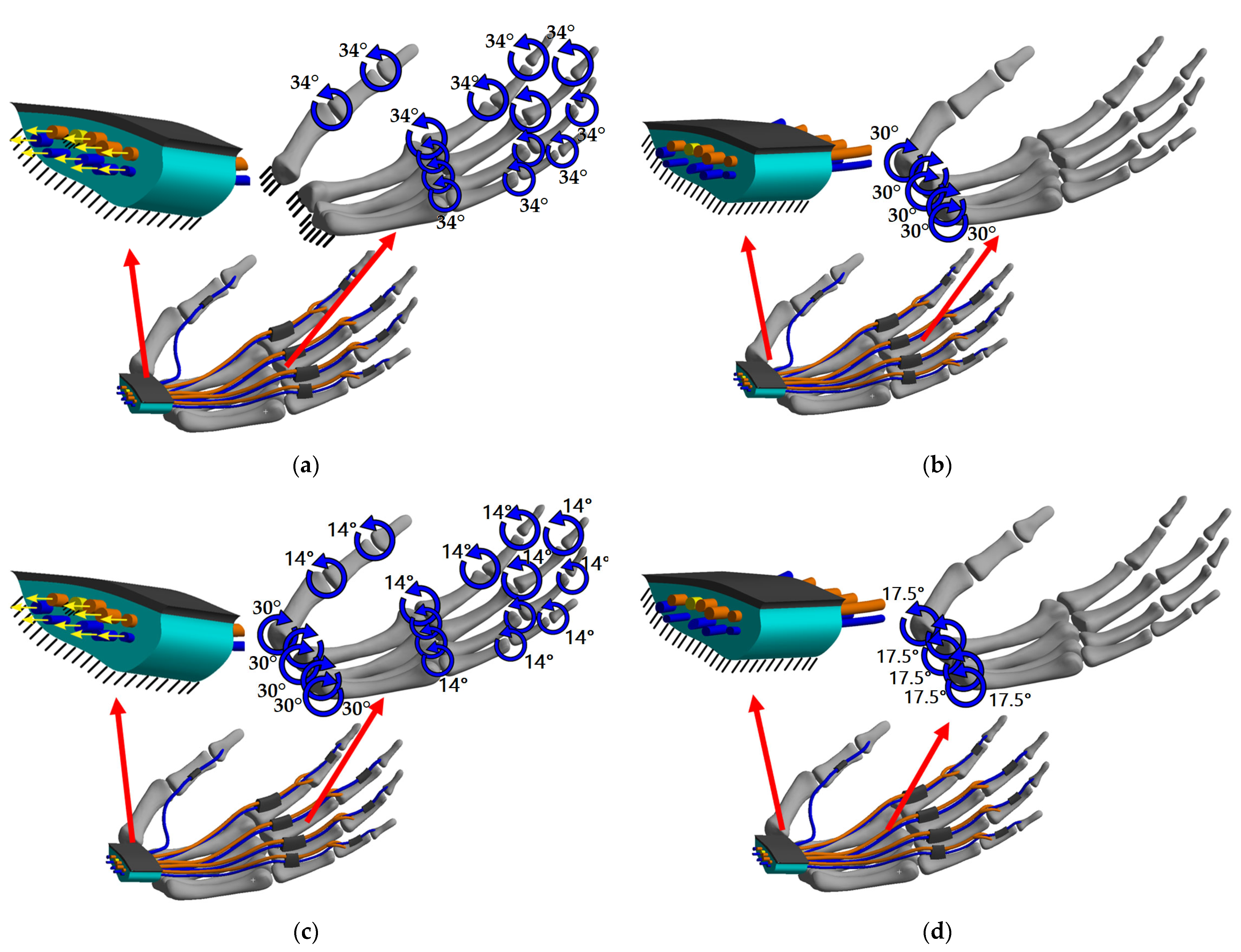
2.3. Boundary and Contact Conditions

The final finite-element model has 40 solid bodies with contact and joint. The simulations were performed in the ANSYS Mechanical APDL application package (ANSYS Inc., Canonsburg, PA, USA). Two types of contact and one type of joint are provided in the model according to the physiological and anatomical features of the wrist. The first contact type is “bonded”. In this contact, defined geometries act like one body. Bodies cannot move (no slide and no separate) and rotate between each other. This way the tendon attachment to the phalanges is simulated. The second contact type is “no separation”. Once the contact is detected, the target and contact surface are tied up for the rest of the analysis. Slide is possible, but the nodes in contact are bonded to the target surface in a normal direction. This type of contact simulates the interaction of tendons and annular ligaments. The only type of joint is “Revolute”. A joint typically serves as a junction where bodies are joined together. Joint types are characterized as fixed or free depending on their rotational and translational degrees of freedom.
A Revolute type means five constrained degrees of freedom with all axis motion and rotation around X and Y axes. Thus, only one free degree of freedom is available, i.e., rotation around Z axis. This simulates the flexion/extension of the fingers and wrist. Details of the contact of all bodies can be found in Table 2.
The finite-element mesh was generated according to the contact interactions of the bodies. Hexahedral and tetrahedral elements were used. Hexahedral elements predominated in the areas of the tendon, SSCT, transverse ligament, and annular ligaments. Tetrahedral elements predominate in the phalanges of the fingers. The whole model included 422,779 nodes and 122,486 elements.
Four sets of boundary conditions were chosen to simulate finger flexion, wrist extension, subsequent fingers flexion and wrist flexion. The stress-strain state was determined for all 40 solids bodies by finite-element modeling with static analysis. The proximal SSCT region was rigidly fixed in all three cases. The carpal bones were modeled in this way. The median nerve was rigidly fixed at the proximal and distal areas.

2.3.1. Finger Flexion (Case 1)

Finger flexion with a fixed wrist was modeled in this case. The proximal parts of the metacarpals were rigidly fixed. Each rotating pair of phalanges were set to a rotation angle of 34 degrees. The proximal parts of the tendons were displaced by 7.7 mm (Figure 2a).

2.3.2. Wrist Extension (Case 2)

Wrist extension with fixed fingers phalanges were modeled in this case. The proximal parts of the metacarpals were allowed to rotate as well as the fingers phalanges as in case 1. Rotating metacarpals were set to a rotation angle of 30 degrees. The proximal parts of the tendons were free (Figure 2b).

2.3.3. Wrist Extension and Subsequent Fingers Flexion (Case 3)

Two steps of wrist extension and subsequent fingers flexion were modeled in this case. In the first step, the proximal parts of the metacarpals were allowed to rotate with fixed fingers phalanges. Rotating metacarpals were set to a rotation angle of 30 degrees. The proximal parts of the tendons were free (Figure 2c). In the second step, the rotation of the metacarpals proximal parts was stopped at thirty degrees. The proximal parts of the tendons were displaced by 5 mm. Each rotating pair of phalanges were set to a rotation angle of 14 degrees.

2.3.4. Wrist Flexion (Case 4)

Wrist flexion with fixed fingers were modeled in the last case. The proximal parts of the metacarpals were allowed to rotate. Rotating metacarpals were set to a rotation angle of 17.5 degrees. The proximal parts of the tendons were free (Figure 2d).

3. Results

3.1. Case 1: Fingers Flexion

Proximal displacement of the deep flexor and superficial flexor tendons were set as an external load and amounted to 7.7 mm, and the rotation angle between each pair of phalanges was 34° degrees. The applied load simulated a slight finger flexion and could not be a cause of large stress on the median nerve. The maximum von Mises stress in the median nerve was 227.5 Pa (Table 3) and was located near the proximal edge of the carpal tunnel (Figure 3a–c and Figure 4). Total median nerve displacement was 0.032 mm. However, SSCT total movement due to tendon excursion reached 0.79 mm and pressure was 67.6 Pa. At the same time, the transverse ligament maximum stress was 502.2 Pa.

3.2. Case 2: Wrist Extension

Rotation of the proximal areas of the metacarpals was set as an external load and amounted to 30° degrees. The applied load simulated a slight wrist extension. The maximum Mises stress in the median nerve was 218.1 Pa (Table 3) and was located near the proximal edge of the carpal tunnel (Figure 3d–f and Figure 4). Total median nerve displacement was 0.024 mm. However, SSCT total movement due to tendon excursion reached 0.81 mm and the pressure was 189.3 Pa. The transverse ligament stress in this case was 1785.9 Pa.

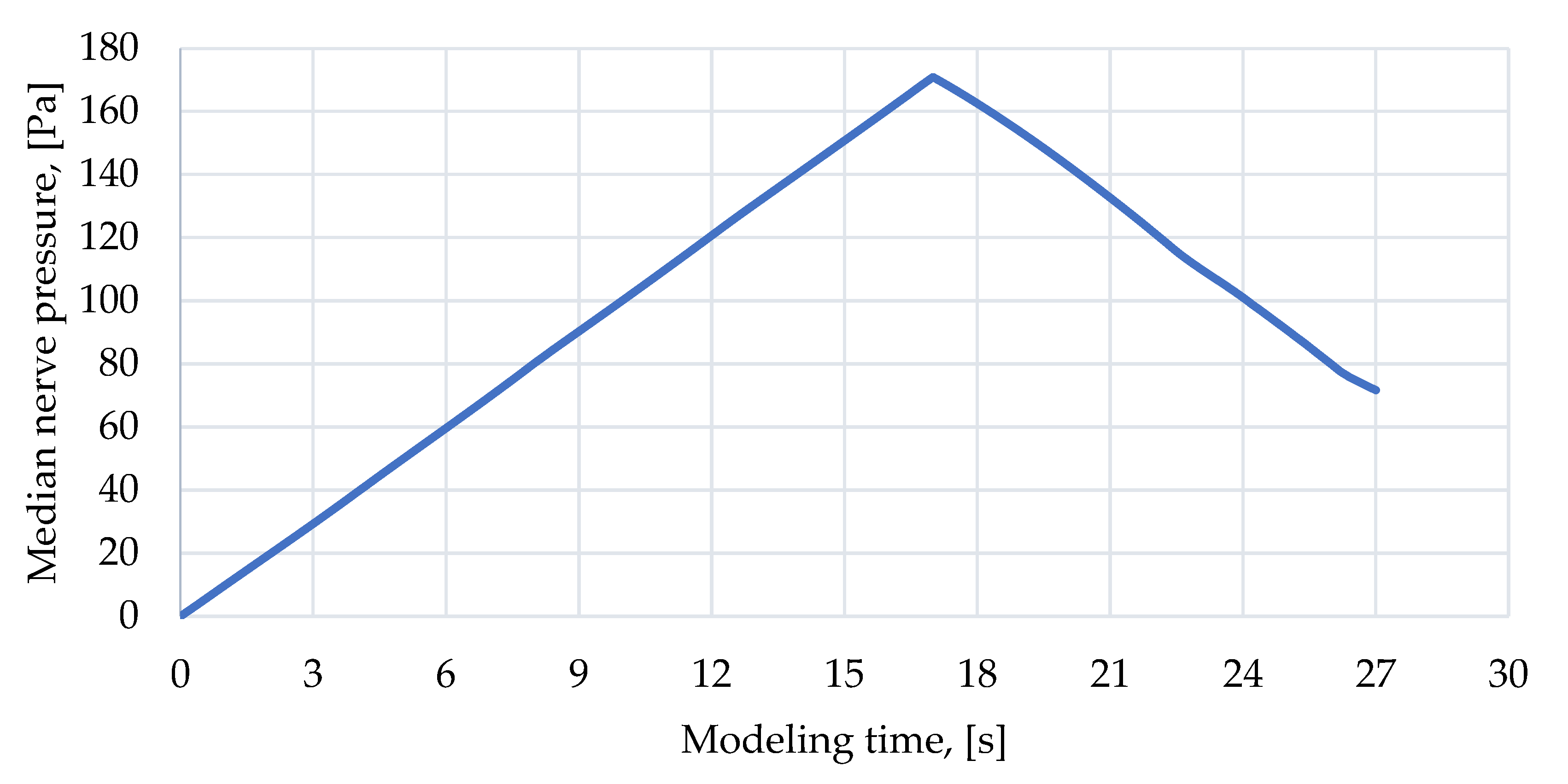
3.3. Case 3: Wrist Extension and Subsequent Fingers Flexion

The simulation consisted of two steps. The first step was wrist extension and the second was subsequent fingers flexion. The maximum Mises stress in the median nerve reached 226.48 Pa at the end of the first step. It was noticed that the pressure decreased to 129 Pa (Figure 5) during the second step. The pressure decrease was related to the tendon direction excursion. Movement toward the carpal bones was noticed during wrist extension, and movement toward the transverse ligament was noticed during finger flexion. Thus, the median nerve was unloaded in the second step. However, SSCT total movement due to tendon excursion and pressure reached, respectively, 0.92 mm and 225.3 Pa at the end of second step. The transverse bundle stress did not decrease, and was 2313.1 Pa at the end of the second step.

3.4. Case 4: Wrist Flexion

Rotation of the proximal metacarpal bones was set as an external load and was 17.5° degrees in the orbital direction compared to the first case. The maximum Mises stress in the median nerve was 197.6 Pa (Table 3). Total median nerve displacement was 0.023 mm (Figure 3 and Figure 4). SSCT total movement due to tendon excursion reached 0.67 mm, and pressure was 66.3 Pa. At the same time, the transverse ligament stress was 1505.7 Pa.

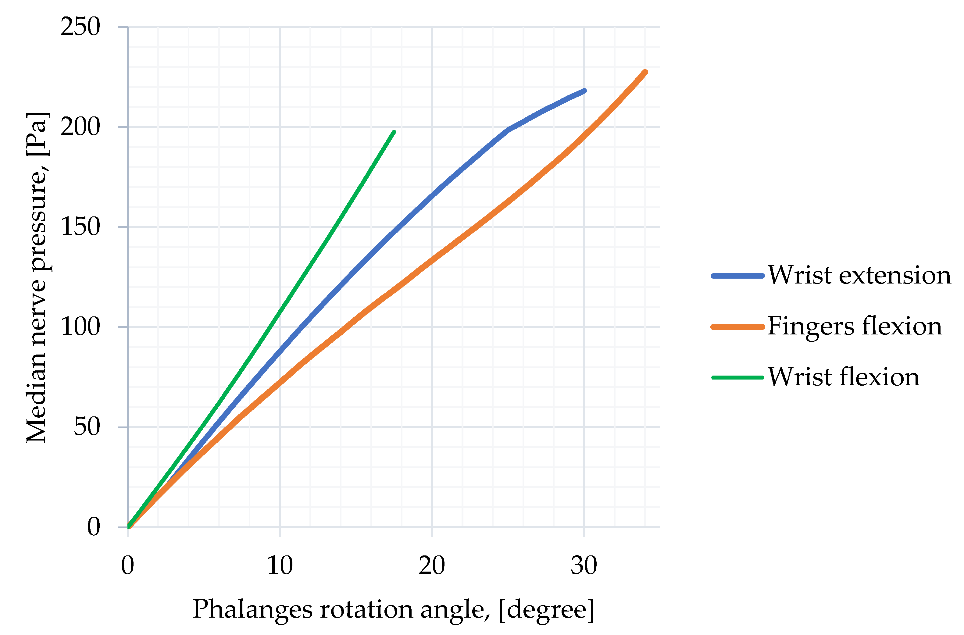
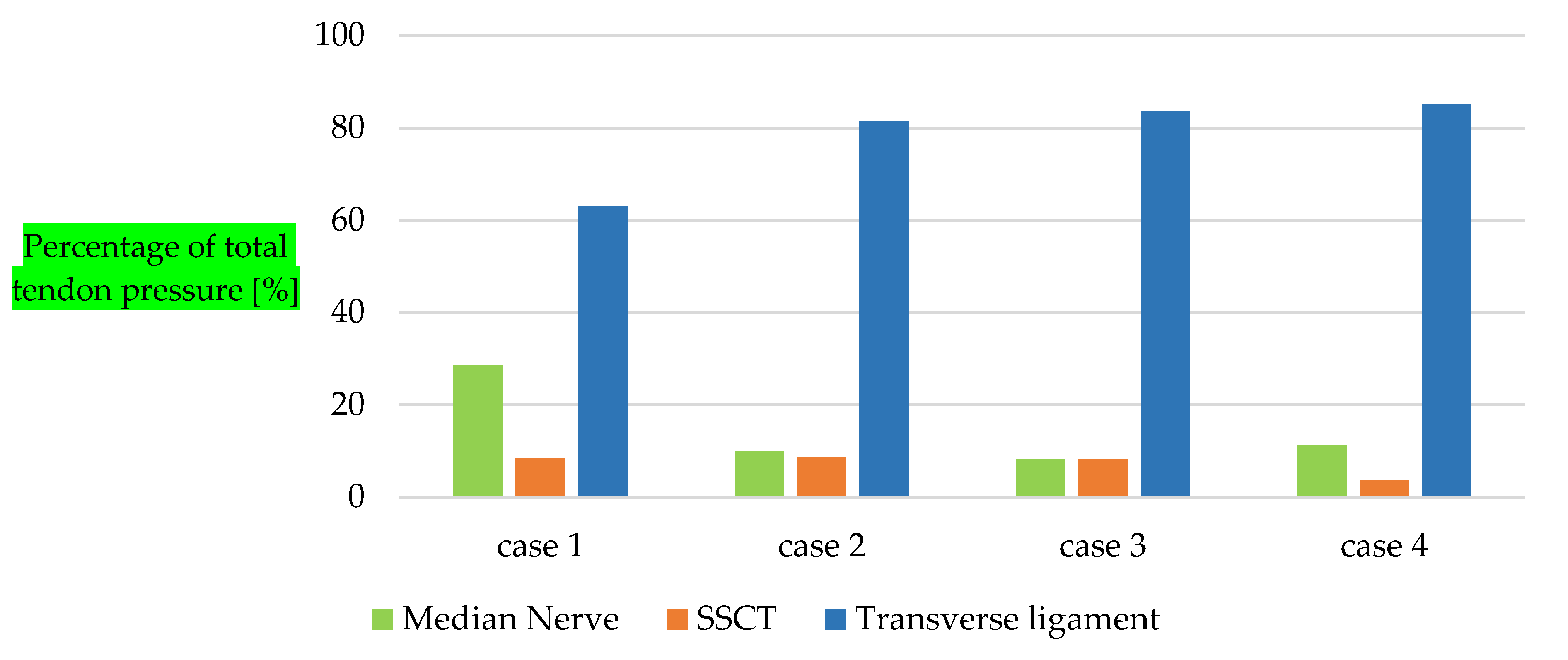
3.5. Comparison of Compression Rate

Once the four cases were solved, a comparison of compression rates was carried out. A graph of the pressure in the median nerve as a function of the phalangeal angle of rotation is illustrated in Figure 4. Case three is hidden, since by definition it is a continuation of case two. It is worth noting that in each case, the maximum angle of the phalanges was different: 34, 30, and 17.5 degrees, respectively, in cases one, two, and four. However, compression rates can be compared. Wrist flexion showed the greatest rate of median nerve compression than the other movements studied. Wrist flexion was typical for the Phalen test (the patient flexes both hands 90 degrees) and caused the greatest rate of compression. The lowest rate of compression was noticed during finger flexion. Finger flexion did not cause flexion of the tendons in the carpal tunnel, and therefore there was less movement of the tendons near the median nerve than during flexion/extension of the wrist.

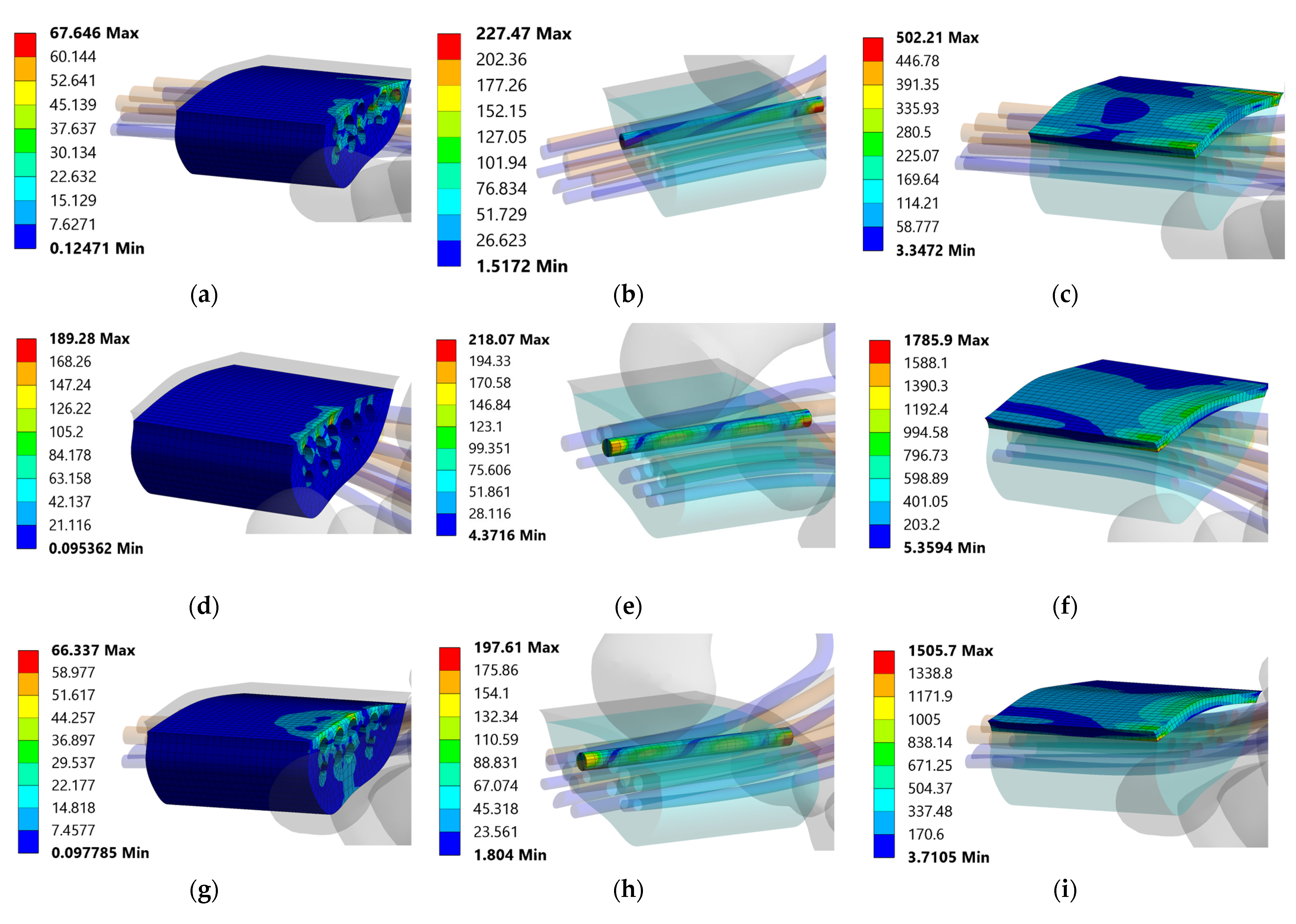
3.6. Pressure Distribution

Investigated finger and hand movements caused pressure in the carpal tunnel, median nerve, and transverse ligament. The main cause of pressure was the movement of tendons in the soft tissue of the carpal tunnel. The movement of the tendons is like an external load for the carpal tunnel system. The external load caused by the tendons is distributed to the surrounding tissues. Obviously, tighter fabrics take most of the load, but to know how much, it is necessary to make a calculation. Figure 6 shows the percentage pressure distribution over the median nerve, transverse ligament, and SSCT. The histogram shows the relative pressure distribution, where 100% is the total load of all three objects. It can be seen that during finger flexion (case 1) the median nerve takes almost 30% of the total load, when in other cases this figure is at the level of 10%. At the same time, the transverse ligament takes more than 80% of the load during flexion/extension of the wrist. This suggests that when the wrist is flexed/extended, the transverse ligament takes the mechanical load first and the median nerve takes the mechanical load when the fingers are flexed.

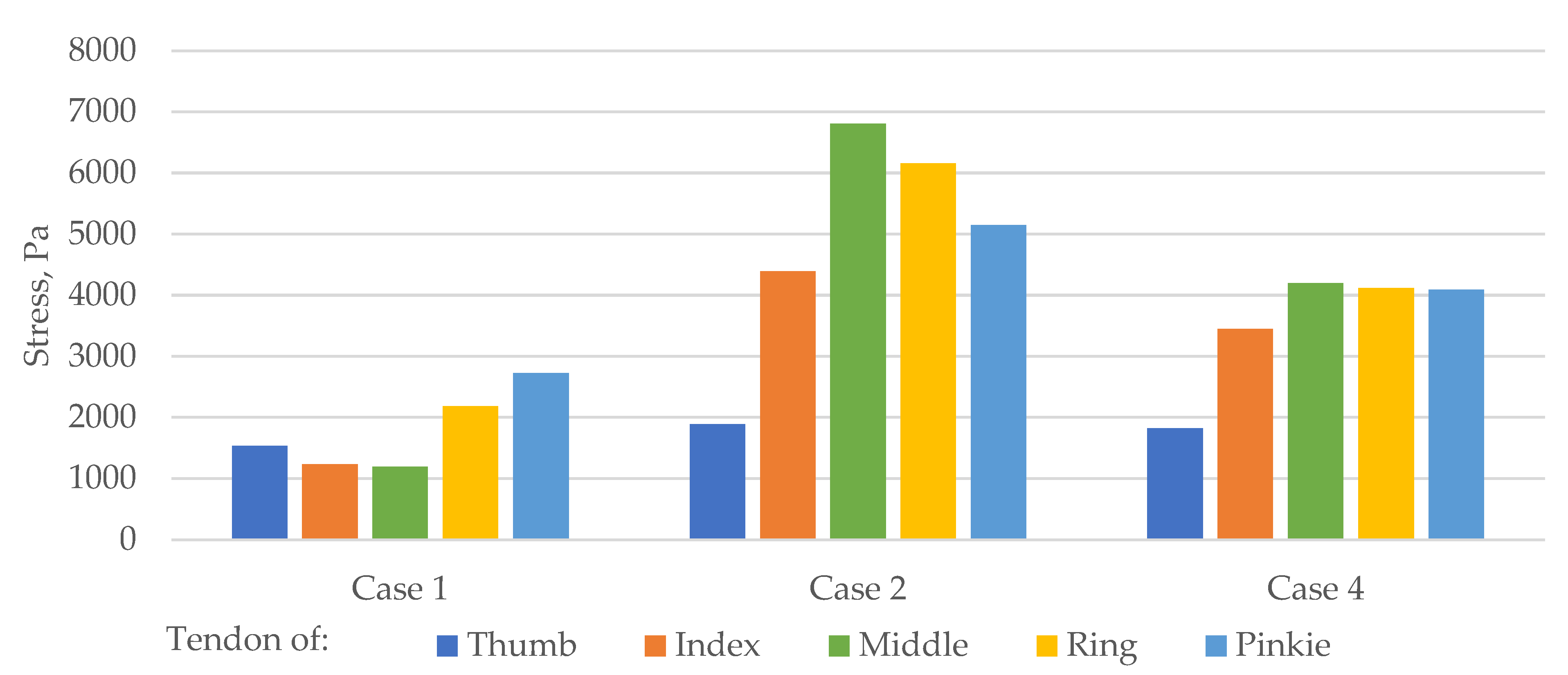
3.7. Tendon Stress in Carpal Tunnel Area

The comparison of tendon movement with external loading for the carpal tunnel system was uneven because each tendon has its own unique shape and location in the area of the carpal tunnel. Each finger has two flexor tendons, except for the thumb, which has one. Among the two tendons for each finger, maximum tension was taken and is shown for cases 1, 2, and 4 in Figure 7.
The distribution of stresses over the flexor tendons during various hand movements was obtained. The uneven distribution of stresses during different movements is noticeable. The maximum finger flexion stress (case 1) was 2727.2 Pa in the pinky finger. However, the maximum stress during extension and flexion of the wrist (cases 2 and 4) was 6803.2 Pa and 4119.8 Pa, respectively, in the middle finger.

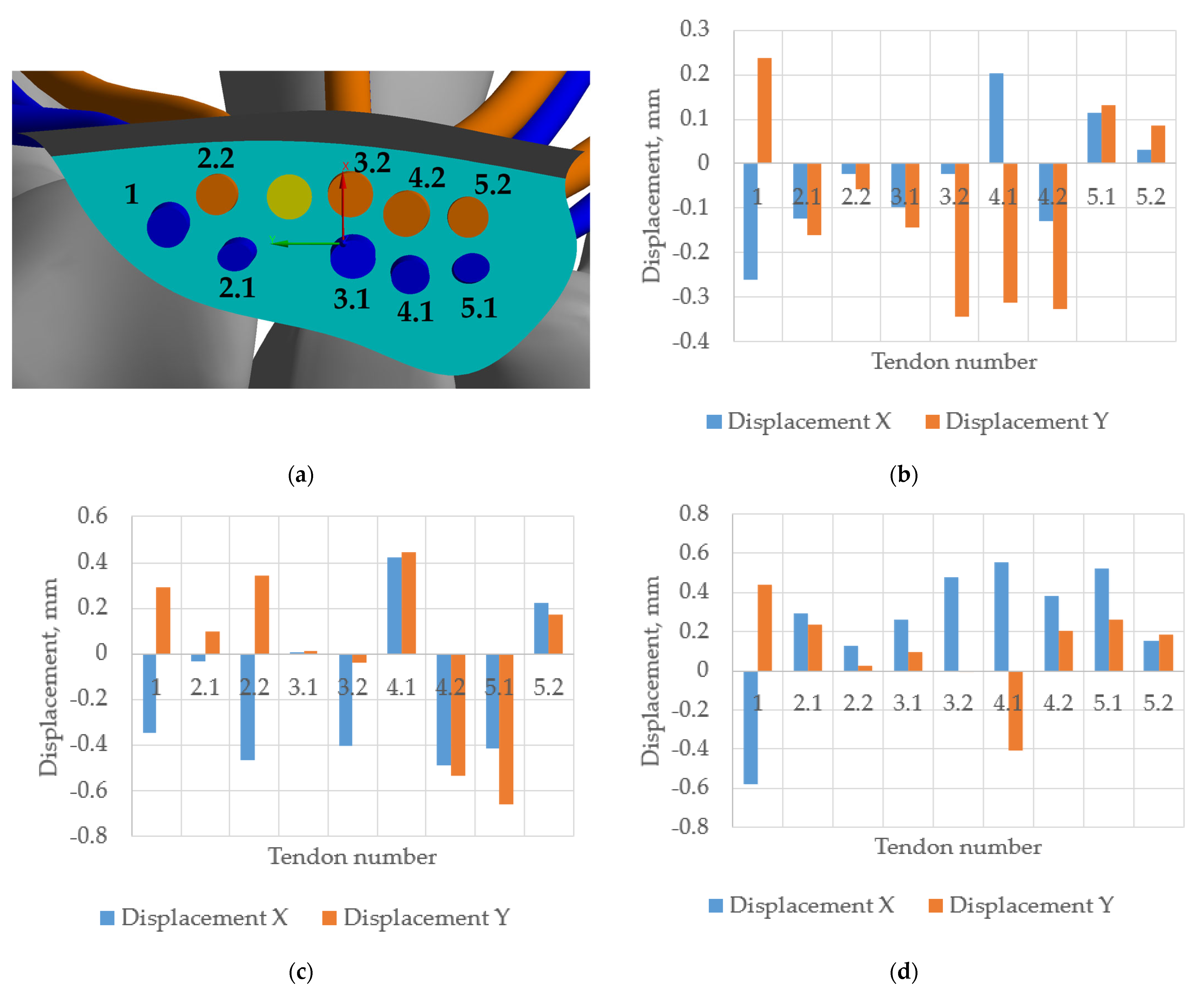
3.8. Tendons Displacement in Carpal Tunnel Area

The superficial and deep tendons passing through the carpal tunnel are stretched by the corresponding muscles and have mobility in the transverse section of the carpal tunnel. The X and Y directional displacement with respect to the coordinate system (Figure 8a) of the finger flexor tendons were obtained. In Figure 8b–d, blue shows movements relative to the X-axis, and orange shows movements relative to the Y-axis. The coordinate system is in the geometric center of the carpal tunnel, with the X-axis pointing toward the transverse ligament, the Y-axis pointing perpendicular to it, and the Z-axis pointing toward the flexor muscles. The largest tendon displacements were seen during hand flexion (Figure 8d) (case 4).

4. Discussion

The results show that compression of the median nerve occurs faster during wrist flexion than during the wrist extension or the fingers flexion, which is consistent with experimental studies [26]. Extension and flexion of the wrist is a typical movement of the Phalen test, which is used to diagnose carpal tunnel syndrome. The patient flexes and extends the wrist 90 degrees and the median nerve experiences compression [27]. In our studies, the maximum flexion/extension angle was 17.5 degrees. Further studies are required to obtain 90-degree hand flexion/extension results.
The observed pressure on the median nerve decreased in the two-step simulation (Figure 5, case 3) indicating opposite loading areas during wrist extension and finger flexion sequences. It is assumed that with an increase in the phalangeal angle of finger flexion after a slight decrease, the compression will further increase. However, the existence of movements that reduce median nerve compression can help to create simulators and exercises for decompression.
This study focused on finite element modeling of the finger, carpal bone, and tendon system, and determined the effect of tendon movement on median nerve compression. However, a comparison with experimental results is required to validate the data obtained. Nevertheless, determining the pressure inside the carpal tunnel experimentally is problematic due to the tendons and median nerve being enclosed within the carpal tunnel, and any opening of the tunnel or penetration will result in loss of the enclosed space effect and the pressure measurement results will most likely be incorrect. This assumption is a prerequisite for mathematical modeling of carpal tunnel pressure determination compared to experimental approaches. Nevertheless, there are some indirect data in the literature in which the results can be compared. The pressure values in the median nerve obtained in this study coincide with the values obtained experimentally by Lundborg at. al. 1983 [28]. Lundborg at. al. determined the endoneurial fluid pressure in the carpal tunnel over time with an external carpal tunnel load of 30 and 80 mmHg. Normal endoneurial fluid pressure in their study was in the range from 1 to 3 cm H2O (from ~100 to 300 Pa). It can be assumed that the endoneurial fluid applies a similar pressure to the median nerve. In this case, the results of finite-element modeling agree with the experimental data. The median nerve stressed obtained in this study were lower than similar results in other experimental studies [26,28,29,30,31]. However, in such studies, the pressure was measured indirectly and with flexion and extension of the hand up to 90 degrees. In this study, flexion was simulated at 17.5 degrees and extension at 30 degrees. In this case, the results are closer to the neutral position of the wrist than to the maximum flexion or extension to 90 degrees. Comparison of the results obtained using the finite element method with the neutral position of the wrist obtained experimentally shows a good agreement, as in Table 4.
The experimental method of determination of intercarpal pressure usually consists in using a catheter that measures hydrostatic pressure. Finite-element modeling assumes zero pressure at the initial moment of time modeling, but with a neutral wrist the nerve is under slight pressure. This was not taken into account in our work and may be investigate in the near future. However, the stress values obtained in this work can be added to the stress values in the neutral position. Study [7] showed that the median nerve is stressed due to mechanical contact with the surrounding tissues, not due to fluid. Normally, without opening the carpal tunnel, the fluid fills the free cavities or is absorbed by the tissues. Thus, hydrostatic pressure may be one of the indirect indicators of compression. The geometry used in this study is based on CT and MR images of a healthy person without carpal tunnel syndrome. Obviously, the median nerve of a healthy person should not be squeezed excessively, especially considering the small external load. However, using this model, it is possible to estimate the influence of various mechanical factors on the compression of the median nerve [5]. An increase in the median nerve or tendon cross-section will increase the load on the median nerve. The close proximity of the tendons and median nerve will also increase the load on the median nerve. These may also be subjects for further research.
The choice of contact interaction between the median nerve and the SSCT can influence the results of the study. This study used no separation connections. Tendon anatomy is arranged in such a way that their tension pulls the SSCT away from the median nerve. The median nerve stretches or compresses depending on the movement of the tendon. The model developed in this study accounts for the effect of each tendon separately, while this is not possible with tests similar to the Phalen test or any other tests.
Among all four cases of motion considered in this paper, it was possible to identify some important mechanical features that characterize the corresponding motion. The most important characteristic is the rate of median nerve compression depending on the type of movement, because when the angle of rotation of the corresponding phalanges increases, this rate is expected to remain unchanged. Then, the maximum compression corresponds to the maximum compression rate obtained in this study. Calculations revealed the highest compression rate for wrist flexion. Nevertheless, other significant factors were observed. For example, the distribution of pressure between the median nerve, SSCT, and transverse ligament during different movements showed that during finger flexion the median nerve takes up to 30% of the load, while during other movements less than 10%. However, the actual stress was less than that of wrist flexion. Thus, the most traumatic movement of the studied in this work was wrist flexion, but taking into account the external load can affect this result. For example, loading the distal phalanges can greatly increase compression of the median nerve, and if it is considered that the median nerve takes up to 30% of the wrist canal load when flexing the fingers, the resultant pressure on the median nerve can be greater than when flexing the wrist.
The importance of modeling the entire finger system (phalanges, tendons, and annular ligaments) is evident in this study. Finger flexion changes the geometry of the tendons, and this geometry greatly affects SSCT movement [32]. Mechanical parameters of the SSCT are lower than those of the tendons (Table 1) [23]. The tendons barely change their shape while sliding along the carpal tunnel. However, flexion of the finger changes the shape of the tendons. Without taking into account wrist and finger movement, it is impossible to simulate the external load caused by tendon movement.
Sometimes median nerve overload can be caused not only by the tendon, but also by an external load on the transverse ligament [33]. These mechanical factors together can greatly increase nerve compression. Working with a keyboard and mouse at a computer was studied in [9] and can be an illustrative example. In such a case, the same small tendon movement as in this paper can cause a strong increase in nerve compression.

5. Limitations

The carpal bones move during flexion and extension of the wrist, which changes the geometry of the carpal canal and consequently affects the movement of tendons and the median nerve; this was not taken into account in this study. However, consideration of the carpal bone interaction is a separate complex task considered in many other studies [11,12,13,14,15]. Adding the effect of carpal bone motion would greatly complicate calculations and increase calculation time to an unacceptable level.
Most of the tendon surface area in this study is in the void. The annular ligaments are surrounded by tissue only where tendons pass through. In fact, the tendons are surrounded by connective tissue throughout. Nevertheless, there was a small amount of movement of the tendons in the direction normal to the phalanges compared to movements in the carpal tunnel. This suggests that the boundary conditions used for the calculations were correct.
This study did not take into account friction between the tendons and other modeled objects. Schweize et al. 2003 [34] developed a method to indirectly measure friction between the flexor tendons and pulleys of the middle and ring finger in vivo. The coefficient of friction according to the calculation was µ = 0.075 (±0.021). Moor et al. 2009 [35] determined friction between the flexor tendons and pulleys of eight human cadaver fingers using an isokinetic movement device. The coefficient of friction according to measurement was µ = 0.045 (±0.0028). The values of friction coefficients in these studies will have a slight impact on the results of this study. However, taking into account the friction force between tendons and other objects may be a further research issue.
The modeling of finger and wrist flexion in this study did not take into account the wrist muscles and finger extension tendons. These tissues provide resistance to wrist and finger flexion. Taking these tissues into account will result in increased pressure in the carpal tunnel. However, the wrist muscles and finger extensor tendons do not pass through the carpal tunnel, and therefore do not contact the median nerve.
In this study, the median nerve was considered only in the carpal tunnel region, because the aim of the study was to determine the effect of tendon movement on median nerve compression. However, the median nerve innervates fingers 1–3 of the wrist and is anatomically attached to the tissues of the fingers. This influences the results of the solution; however, determination of the places of median nerve attachment distal to the carpal tunnel by MRI is very difficult due to its size.

6. Conclusions

The model developed in this study is a step toward the development of a personalized technique for determining median nerve compression by finite-element modeling. Compression of the median nerve ranged from 129 Pa to 227 Pa during various wrist movements. The results show that compression of the median nerve occurs faster during wrist flexion than wrist extension or fingers flexion. A decrease in compression during finger flexion was noticed in the case of extension of the wrist with subsequent finger flexion. The pressure distribution between the median nerve, SSCT, and transverse ligament was shown as a percentage for all four cases of wrist and finger movement. The distribution of stress between the tendons for all fingers in all four cases was obtained. Tendon displacement within the carpal tunnel was also demonstrated.
The application of mathematical modeling for the diagnosis and treatment of various pathologies has been widely developed all over the world. This study describes a method of such modeling for the carpal tunnel and fingers. The developed model accounts for the influence of various hand and finger movements on median nerve compression. Our results may be useful in the diagnosis and treatment of carpal tunnel syndrome, which is most frequently encountered in pathologies of the peripheral nervous system. Further development of the model will improve the quality of diagnosis of carpal tunnel syndrome.

Author Contributions

Conceptualization, A.G.K. and S.P.; methodology, A.G.K. and S.P.; Investigation, S.P. and A.G.K.; writing—original draft preparation, Y.K., S.P. and A.G.K.; writing—review and editing, A.G.K. and S.P.; funding acquisition, A.G.K. All authors have read and agreed to the published version of the manuscript.

Funding

This work was supported by Russian Science Foundation and Perm region (No. 22-21-20067, https://rscf.ru/en/project/22-21-20067 accessed on 1 January 2023).

Institutional Review Board Statement

Not applicable.

Informed Consent Statement

Not applicable.

Data Availability Statement

Not applicable.

Conflicts of Interest

The authors declare no conflict of interest.

References

  1. Laymon, M.; Petrofsky, J.; Mc Kivigan, J.; Lee, H.; Yim, J. Effect of Heat, Cold, and Pressure on the Transverse Carpal Ligament and Median Nerve: A Pilot Study. Med. Sci. Monit. 2015, 21, 446–451. [Google Scholar] [CrossRef] [PubMed] [Green Version]
  2. Lundborg, G.; Gelberman, R.H.; Minteer-Convery, M.; Lee, Y.F.; Hargens, A.R. Median Nerve Compression in the Carpal Tunnel—Functional Response to Experimentally Induced Controlled Pressure. J. Hand Surg. Am. 1982, 7, 252–259. [Google Scholar] [CrossRef] [PubMed]
  3. Werner, R.A.; Andary, M. Electrodiagnostic Evaluation of Carpal Tunnel Syndrome. Muscle Nerve 2011, 44, 597–607. [Google Scholar] [CrossRef] [PubMed] [Green Version]
  4. Sonoo, M.; Menkes, D.L.; Bland, J.D.P.; Burke, D. Nerve Conduction Studies and EMG in Carpal Tunnel Syndrome: Do They Add Value? Clin. Neurophysiol. Pract. 2018, 3, 78–88. [Google Scholar] [CrossRef] [PubMed]
  5. Peshin, S.E.; Karakulova, Y.V.; Nyashin, Y.I.; Nyashin, M.M. Carpal Tunnel Syndrome in Terms of Biomechanics. Literature Review. Russ. J. Biomech. 2022, 26, 9–13. [Google Scholar]
  6. Guo, X.; Fan, Y.; Li, Z.M. Three Dimensional Finite Element Analysis on the Morphological Change of the Transverse Carpal Ligament. In Proceedings of the 2007 IEEE/ICME International Conference on Complex Medical Engineering, CME, Beijing, China, 23–27 May 2007. [Google Scholar]
  7. Ko, C.; Brown, T.D. A Fluid-Immersed Multi-Body Contact Finite Element Formulation for Median Nerve Stress in the Carpal Tunnel. Comput. Methods Biomech. Biomed. Eng. 2007, 10, 343–349. [Google Scholar] [CrossRef] [Green Version]
  8. Javanmardian, A.; HaghPanahi, M. 3 Dimensional Finite Element Analysis of the Human Wrist Joint without Ligaments under Compressive Loads. In Proceedings of the 2010 17th Iranian Conference of Biomedical Engineering, ICBME, Isfahan, Iran, 3–4 November 2010. [Google Scholar]
  9. Mouzakis, D.E.; Rachiotis, G.; Zaoutsos, S.; Eleftheriou, A.; Malizos, K.N. Finite Element Simulation of the Mechanical Impact of Computer Work on the Carpal Tunnel Syndrome. J. Biomech. 2014, 47, 2989–2994. [Google Scholar] [CrossRef]
  10. Yao, Y.; Erdemir, A.; Li, Z.M. Finite Element Analysis for Transverse Carpal Ligament Tensile Strain and Carpal Arch Area. J. Biomech. 2018, 73, 210–216. [Google Scholar] [CrossRef]
  11. Oflaz, H.; Gunal, I. Maximum Loading of Carpal Bones during Movements: A Finite Element Study. Eur. J. Orthop. Surg. Traumatol. 2019, 29, 47–50. [Google Scholar] [CrossRef]
  12. Perevoshchikova, N.; Moerman, K.M.; Akhbari, B.; Bindra, R.; Maharaj, J.N.; Lloyd, D.G.; Cerezo, M.G.; Carr, A.; Vaquette, C.; Saxby, D.J. Finite Element Analysis of the Performance of Additively Manufactured Scaffolds for Scapholunate Ligament Reconstruction. PLoS ONE 2021, 16, e0256528. [Google Scholar] [CrossRef]
  13. Marqués, R.; Melchor, J.; Sánchez-Montesinos, I.; Roda, O.; Rus, G.; Hernández-Cortés, P. Biomechanical Finite Element Method Model of the Proximal Carpal Row and Experimental Validation. Front. Physiol. 2022, 12, 2429. [Google Scholar] [CrossRef]
  14. Yokota, H.; Yasui, M.; Hirai, S.; Hatayama, N.; Ohshima, S.; Nakano, T.; Naito, M. Evaluation of the Pressure on the Dorsal Surface of the Distal Radius Using a Cadaveric and Computational Model: Clinical Considerations in Intersection Syndrome and Colles’ Fracture. Anat. Sci. Int. 2020, 95, 38–46. [Google Scholar] [CrossRef]
  15. Wei, Y.; Zou, Z.; Wei, G.; Ren, L.; Qian, Z. Subject-Specific Finite Element Modelling of the Human Hand Complex: Muscle-Driven Simulations and Experimental Validation. Ann. Biomed. Eng. 2020, 48, 1181–1195. [Google Scholar] [CrossRef] [Green Version]
  16. Natali, A.N.; Carniel, E.L.; Pavan, P.G.; Dario, P.; Izzo, I. Hyperelastic Models for the Analysis of Soft Tissue Mechanics: Definition of Constitutive Parameters. In Proceedings of the First IEEE/RAS-EMBS International Conference on Biomedical Robotics and BiomechatronicsBioRob, Pisa, Italy, 20–22 February 2006. [Google Scholar]
  17. Ogden, R. Non-Linear Elastic Deformations. Eng. Anal. Bound. Elem. 1984, 1, 119. [Google Scholar] [CrossRef]
  18. Main, E.K.; Goetz, J.E.; Baer, T.E.; Klocke, N.F.; Brown, T.D. Volar/Dorsal Compressive Mechanical Behavior of the Transverse Carpal Ligament. J. Biomech. 2012, 45, 1180–1185. [Google Scholar] [CrossRef] [Green Version]
  19. Main, E.K.; Goetz, J.E.; James Rudert, M.; Goreham-Voss, C.M.; Brown, T.D. Apparent Transverse Compressive Material Properties of the Digital Flexor Tendons and the Median Nerve in the Carpal Tunnel. J. Biomech. 2011, 44, 863–868. [Google Scholar] [CrossRef] [Green Version]
  20. Ma, Z.; Hu, S.; Tan, J.S.; Myer, C.; Njus, N.M.; Xia, Z. In Vitro and in Vivo Mechanical Properties of Human Ulnar and Median Nerves. J. Biomed. Mater. Res. Part A 2013, 101A, 2718–2725. [Google Scholar] [CrossRef]
  21. Chang, C.T.; Chen, Y.H.; Lin, C.C.K.; Ju, M.S. Finite Element Modeling of Hyper-Viscoelasticity of Peripheral Nerve Ultrastructures. J. Biomech. 2015, 48, 1982–1987. [Google Scholar] [CrossRef]
  22. Matsuura, Y.; Thoreson, A.R.; Zhao, C.; Amadio, P.C.; An, K.N. Development of a Hyperelastic Material Model of Subsynovial Connective Tissue Using Finite Element Modeling. J. Biomech. 2016, 49, 119–122. [Google Scholar] [CrossRef] [Green Version]
  23. Festen-Schrier, V.J.M.M.; Amadio, P.C. The Biomechanics of Subsynovial Connective Tissue in Health and Its Role in Carpal Tunnel Syndrome. J. Electromyogr. Kinesiol. 2018, 38, 232–239. [Google Scholar] [CrossRef]
  24. Kuchumov, A.G.; Vedeneev, V.; Samartsev, V.; Khairulin, A.; Ivanov, O. Patient-Specific Fluid–Structure Interaction Model of Bile Flow: Comparison between 1-Way and 2-Way Algorithms. Comput. Methods Biomech. Biomed. Engin. 2021, 24, 1693–1717. [Google Scholar] [CrossRef] [PubMed]
  25. Pistoia, W.; Van Rietbergen, B.; Lochmüller, E.M.; Lill, C.A.; Eckstein, F.; Rüegsegger, P. Estimation of Distal Radius Failure Load with Micro-Finite Element Analysis Models Based on Three-Dimensional Peripheral Quantitative Computed Tomography Images. Bone 2002, 30, 842–848. [Google Scholar] [CrossRef] [PubMed]
  26. Bauman, T.D.; Gelberman, R.H.; Mubarak, S.J.; Garfin, S.R. The Acute Carpal Tunnel Syndrome. Clin. Orthop. Relat. Res. 1981, 156, 151–156. [Google Scholar] [CrossRef]
  27. Kuschner, S.H.; Ebramzadeh, E.; Johnson, D.; Brien, W.W.; Sherman, R. Tinel’s Sign and Phalen’s Test in Carpal Tunnel Syndrome. Orthopedics 1992, 15, 1297–1302. [Google Scholar] [CrossRef] [PubMed]
  28. Lundborg, G.; Myers, R.; Powell, H. Nerve Compression Injury and Increased Endoneurial Fluid Pressure: A “Miniature Compartment Syndrome”. J. Neurol. Neurosurg. Psychiatry 1983, 46, 1119–1124. [Google Scholar] [CrossRef]
  29. Rojviroj, S.; Sirichativapee, W.; Kowsuwon, W.; Wongwiwattananon, J.; Tamnanthong, N.; Jeeravipoolvarn, P. Pressures in the Carpal Tunnel. A Comparison between Patients with Carpal Tunnel Syndrome and Normal Subjects. J. Bone Jt. Surg. Ser. B 1990, 72, 516–518. [Google Scholar] [CrossRef]
  30. Luchetti, R.; Schoenhuber, R.; Alfarano, M.; Deluca, S.; De Cicco, G.; Landi, A. Carpal Tunnel Syndrome: Correlations between Pressure Measurement and Intraoperative Electrophysiological Nerve Study. Muscle Nerve 1990, 13, 1164–1168. [Google Scholar] [CrossRef]
  31. Hamanaka, I.; Okutsu, I.; Shimizu, K.; Takatori, Y.; Ninomiya, S. Evaluation of Carpal Canal Pressure in Carpal Tunnel Syndrome. J. Hand Surg. Am. 1995, 20, 848–854. [Google Scholar] [CrossRef]
  32. Dilley, A.; Greening, J.; Lynn, B.; Leary, R.; Morris, V. The Use of Cross-Correlation Analysis between High-Frequency Ultrasound Images to Measure Longitudinal Median Nerve Movement. Ultrasound Med. Biol. 2001, 27, 1211–1218. [Google Scholar] [CrossRef]
  33. Guo, X.; Fan, Y.; Li, Z.M. Effects of Dividing the Transverse Carpal Ligament on the Mechanical Behavior of the Carpal Bones under Axial Compressive Load: A Finite Element Study. Med. Eng. Phys. 2009, 31, 188–194. [Google Scholar] [CrossRef]
  34. Schweizer, A.; Frank, O.; Ochsner, P.E.; Jacob, H.A.C. Friction between Human Finger Flexor Tendons and Pulleys at High Loads. J. Biomech. 2003, 36, 63–71. [Google Scholar] [CrossRef]
  35. Moor, B.K.; Nagy, L.; Snedeker, J.G.; Schweizer, A. Friction between Finger Flexor Tendons and the Pulley System in the Crimp Grip Position. Clin. Biomech. 2009, 24, 20–25. [Google Scholar] [CrossRef]
Figure 1. Geometry of the model (b) based on MRI (a).
Applsci 13 01219 g001
Figure 2. Boundary condition for all cases. (a) finger flexion, (b) wrist extension, (c) wrist extension and subsequent fingers flexion, (d) wrist flexion.
Applsci 13 01219 g002
Figure 3. Stress [Pa] (a) SSCT with fingers flexion, (b) median nerve with fingers flexion, (c) transverse ligament with fingers flexion, (d) SSCT with wrist extension, (e) median nerve with wrist extension, (f) transverse ligament with wrist extension, (g) SSCT with wrist flexion, (h) median nerve with wrist flexion, (i) transverse ligament with wrist flexion.
Applsci 13 01219 g003
Figure 4. Dependence of pressure in the median nerve on the angle of the phalanx’s rotation.
Applsci 13 01219 g004
Figure 5. Wrist extension and subsequent fingers flexion.
Applsci 13 01219 g005
Figure 6. Pressure distribution in percentage.
Applsci 13 01219 g006
Figure 7. Finger tendon pressure distribution for cases 1, 2 and 4.
Applsci 13 01219 g007
Figure 8. Distribution of directed movements X and Y by tendon (1) Thumb, 2.1−superficial flexor index finger, 2.2−deep flexor index finger, 3.1−superficial flexor middle finger, 3.2−deep flexor middle finger, 4.1−superficial flexor ring finger, 4.2−deep flexor ring finger, 5.1−superficial flexor pinky, 5.2−deep flexor pinky). (a) Coordinate system, (b) case 1 (finger flexion), (c) case 2 (wrist extension), (d) case 4 (wrist flexion).
Applsci 13 01219 g008
Table 1. Mechanical properties of the tissues used in model.
Hyperelastic ParameterReference
Tissuesαµ [Pa]
Annular ligaments10.924.900Main E.K. et al. [18]
Transverse ligament10.924.900Main E.K. et al. [18]
Flexor digitorum deep tendon8.8937.600Main E.K. et al. [19]
Flexor digit superficial tendon 8.8937.600Main E.K. et al. [19]
Subsynovial connective tissue 4.5112.500Matsuura Y. et al. [22]
Median nerve6.512.900Main E.K. et al., Ma Z. et al. [19,20]
Elastic
νE [MPa]
Phalanges and carpal bones0.310,000Pistoia W. et al. [25]
Table 2. Solid bodies contact types.
Solid Body PairInteraction/Contact Type
Distal phalange to Middle phalangeRevolute
Middle phalange to Proximal phalangeRevolute
Proximal phalange to MetacarpalRevolute
Deep flexor tendon to Distal phalangeBonded
Superficial flexor tendon to Middle phalangeBonded
Superficial and Deep flexor tendon to Annular ligamentNo separation
Superficial and Deep flexor tendon to SSCTNo separation
Median nerve to SSCTNo separation
Annular ligament to phalangesBonded
Transverse carpal ligament to SSCTBonded
Table 3. Maximum stress in different movements.
Stress, Pa
MovementSSCTMedian NerveTransverse Ligament
fingers flexion67.6227.5502.2
wrist extension189.3218.11785.9
wrist flexion66.3197.61905.7
Table 4. Comparison of experimental results with the results obtained using the finite element method.
StudyCarpal Tunnel Pressure [Pa]
Bauman et al. [26]266
Lundborg et. el. [28]100–300
Luchetti et al. [30]106–360
Our results197–227
Disclaimer/Publisher’s Note: The statements, opinions and data contained in all publications are solely those of the individual author(s) and contributor(s) and not of MDPI and/or the editor(s). MDPI and/or the editor(s) disclaim responsibility for any injury to people or property resulting from any ideas, methods, instructions or products referred to in the content.

