Article

Numerical and Experimental Analysis of the Oil Flow in a Planetary Gearbox

1
Faculty of Science and Technology, Free University of Bolzano, Piazza Università 5, 39100 Bolzano, Italy
2
Gear Research Center (FZG), Department of Mechanical Engineering, School of Engineering and Design, Technical University of Munich, Boltzmannstraße 15, 85748 Garching, Germany
*
Author to whom correspondence should be addressed.
Appl. Sci. 2023, 13(2), 1014; https://doi.org/10.3390/app13021014
Submission received: 21 December 2022 / Revised: 9 January 2023 / Accepted: 10 January 2023 / Published: 11 January 2023
(This article belongs to the Special Issue Modern Research of Gears and Power Transmission)

Abstract

:
The circular layout and the kinematics of planetary gearboxes result in characteristic oil flow phenomena. The goal of this paper is to apply a new remeshing strategy, based on the finite volume method, on the numerical analysis of a planetary gearbox and its evaluation of results as well as its validation. The numerical results are compared with experimental data acquired on the underlying test rig with high-speed camera recordings. By use of a transparent housing cover, the optical access in the front region of the gearbox is enabled. Different speeds of the planet carrier and immersion depths are considered. A proper domain partitioning and a specifically suited mesh-handling strategy provide a highly efficient numerical model. The open-source software OpenFOAM® is used.

1. Introduction

Planetary gearboxes are widely used in mechanical transmissions with great advantages, such as high transmissible torque, power density, high reliability, and efficiency. These gearboxes are composed of four main components: the sun gear, the ring gear, the planet gears, and the planet carrier. The sun is an external gear and is coaxial with the ring gear, which, on the contrary, is an internal gear. The planets are external gears that engage with both the sun and the ring gears. Different arrangements of the sun, the planets, the planet carrier, and the ring gear are possible due to the kinematic degrees of freedom.
Planetary gearboxes are used in several application areas, especially in industrial automation systems, wind power industry, and industrial gear units. For example, they are used in dynamic applications in robotics, where factors such as low backlash and a balanced load distribution are highly valued so to ensure a longer system lifetime and positioning accuracy. Typical applications include machine tools and self-propelled machines, packaging systems, conveyor belts, printing presses, and any context where extremely precise positioning control is required. Compared with other types of geared transmissions, planetary gearboxes allow to design a more compact system, a feature that is always appreciated by machine designers.
In geared transmissions, it is crucial to ensure the proper lubrication of all components, especially when they operate at high speeds or must withstand heavy loads. In this work, a combined experimental–numerical approach is used to investigate the oil phenomena that occur in the FZG internal gear test rig [1,2]. A special transparent housing cover was designed to make the front part of the gearbox visible. This allowed to capture the oil flow by high-speed camera recordings. To analyze the oil distribution, a CFD model was developed. A new mesh-handling technique was applied to build a time efficient simulation model. The CFD results show a high comparability with experimental results for a wide range of operation conditions. The potential of CFD for predicting oil flow is shown.

Literature Review

The first studies on the no-load power losses arising from the interaction of the moving components with the lubricant in planetary gears date back to Gold et al. [3]. They performed theoretical and experimental studies aimed at studying a two-stage planetary gearbox partially immersed in oil. Further analyses by Kettler [4] concentrated on the operating temperature and the heat balance in dip-lubricated planetary gearboxes. The geometrical parameters of the gearbox such as center distance, planet carrier geometry, and the number of planets, as well as the physical properties of the system such as lubricant parameters and immersion depth, were considered to derive analytical equations for the determination of no-load power losses. Subsequent analyses by Da Costa [5] dealt with the impact of different types of lubricant, namely mineral and synthetic oil, on the no-load power losses for dip lubrication. Studies with injection lubrication were conducted by Höhn et al. [6] and Schudy [1], who built the FZG internal gear test rig to investigate the flank load carrying capacity of internal gears, and the influence of circumferential speeds, material combinations, surface finishing, and lubricants. Suggestions for lubrication conditions, surface finishing, and drive direction were provided. De Gevigney et al. [7] performed an experimental campaign on a planetary gearbox aimed at studying the impact of injection volume rate, lubricant temperature, and rotational speed on efficiency. Recent experiments by Boni et al. [8,9] focused on the detailed analysis of the oil distribution in a dip-lubricated planetary gearbox and its efficiency. They used a front housing made from acryl glass that allowed observation of the oil level and its flow during operation. Various observations were made by considering different rotational speeds, lubricant temperatures, and filling levels. As the planet carrier starts to rotate, the oil tends to distribute around the circumference of the covering box creating a dynamic peripheral oil ring. The authors considered the thickness of the oil ring for the estimation of the churning power losses. This phenomenon has not been observed for other gearbox designs, meaning that it is a peculiar characteristic of planetary gearboxes.
Due to the difficult visibility of internal gearbox components, it is not trivial to have a deep understanding of the lubrication mechanisms, especially for systems characterized by a compact design as planetary gearboxes. However, recent developments in computer science made it possible to use numerical approaches to study the specific problem of interest. In the case of gearbox lubrication, Computational Fluid Dynamics (CFD) can offer substantial benefits in the prediction of the oil flow inside the gearbox. Indeed, in the post-processing phase, it is possible to analyze the oil distribution inside the considered gearbox and to derive information on the lubrication behavior of the system. However, due to the complex kinematics of planetary gearboxes and the high computational resources needed, the numerical studies available in the literature are limited. Moreover, sometimes significant modeling simplifications have been adopted, making it difficult to assess the models’ reliability concerning the oil flow predictions. A recent exhaustive literature review on CFD methods applied to the study of gearbox lubrication and efficiency can be found in Maccioni et al. [10]. In the following, the sole CFD studies relative to epicyclic gearboxes are reported.
Bianchini et al. [11,12] exploited the Multiple Reference Frame (MRF) approach to model a planetary gearbox for aeronautic applications. They increased the gear interspacing, i.e., the meshing region between the sun and the planets, and between the planets and the ring gear, was not modelled. In this way, the squeezing effects could not be simulated and the related axial phenomena occurring in the mating zone were neglected. Moreover, only single-phase simulations were performed. The adopted MRF technique is limited to a regime solution of an unsteady problem without information on the transient behavior. Despite low computational effort, the approach lacks an accurate description of multiphase operating conditions and oil flow phenomena.
More advanced numerical techniques, such as the sliding mesh approach and the dynamic remeshing, are suitable for simulating gear rotation and interaction. FZG test rigs are used for experimental studies on efficiency and lubrication [13]. Concli et al. [14,15] implemented a CFD model of a planetary gearbox studying the no-load power losses for different oil temperatures, immersion depths, and planet carrier rotational speeds. The results were validated with experimental data in terms of power losses. Further studies by Concli et al. [16,17,18] introduced an innovative remeshing procedure in the opensource CFD code OpenFOAM® [19] for the simulation of the gear meshing. The strategy is based on the computation of extruded numerical grids connected through numerical interfaces to link the non-conformal nodes. When the quality of the mesh decreases, a new mesh is computed for the new gear position. The results are interpolated and the simulation proceeds. The virtual models could predict the efficiency of the system accurately. This algorithm requires the generation of a new mesh whenever bad-quality elements originate. This means that hundreds of meshes may be needed to complete the simulation.
Cho et al. [20] implemented a CFD model based on the overset mesh approach (also called the overlapping grids method, or chimera framework) [21,22] of a planetary gearbox. Filling levels of 30%, 50%, and 70% of the gearbox volume were analyzed. Owing to the numerical analysis, the system design could be optimized and the thermal behavior could be determined. The authors suggest using high filling levels to increase the cooling effects despite the higher churning losses. The commercial software STAR-CCM+ [23] was used.
Liu et al. [2] investigated the oil distribution of the FZG internal gear test rig, which is also the object of this study, for different oil properties and planet carrier speeds in detail. The finite volume-based CFD implementation included a dynamic remeshing approach to describe the rotation and engagement of the gears. They performed multi-phase simulations by applying the Volume of Fluid (VoF) method. The roller bearings of the planet gear shafts were also modeled in the numerical simulation, but their kinematics were described with a pure rotation around the central axis of the planetary gearbox and not with a roto-translation, which resulted in doubling the computational time. They performed a mesh sensitivity analysis with respect to loss torque and oil distribution to obtain an efficient yet accurate modeling approach. The high level of detail of the developed CFD model allowed for the extraction of information on the oil flow inside the gearbox. Liu et al. [2] indicate that with a rather low filling level, it is possible to supply enough oil to the different machine elements. The commercial software ANSYS FLUENT [24] was used. The simulations were parallelized on 80 cores of a high-performing computer cluster.
As it can be noticed from the literature review on planetary gearboxes, the experimental studies are limited, and the numerical analyses mostly lack validation, particularly concerning the validation of the oil flow, since the internal part of the gearbox could not be visibly accessed. Moreover, significant computational resources were required to run such simulations. To increase confidence in simulation results, validation by experimental investigations in terms of oil flow is fundamental. Furthermore, efficient remeshing strategies can reduce the computational effort required for finite volume-based CFD simulations. This work fits into these objectives, providing side-by-side comparisons of high-speed camera recordings and CFD results of the oil distribution. The system under consideration is the same investigated by Liu et al. [2]. As a new computationally efficient mesh-handling approach is introduced, the implemented numerical model is ideal to analyze the considered gearbox and can be run on “normal” computers without the need for high-performance computing clusters.

2. Materials and Methods

The FZG internal gear test rig is the subject of the investigation and served to validate the simulation results. In the following, a detailed description of the system and the operating conditions is given.

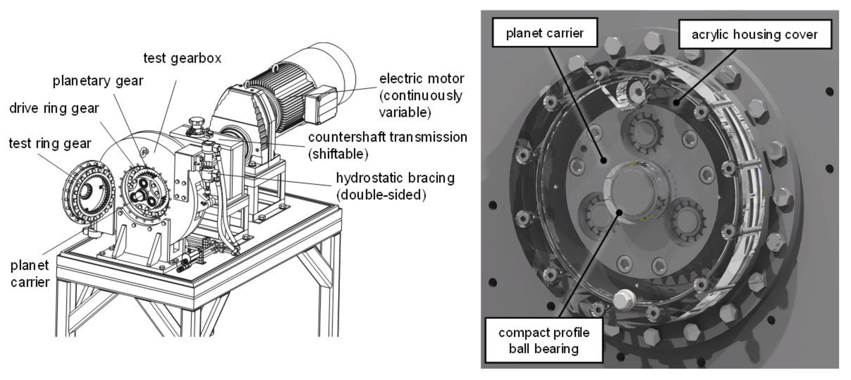
2.1. Object of Investigation

The object of investigation is the FZG internal gear test rig presented in Figure 1 (left). The test rig is composed of a planet carrier, three planet gears, and two ring gears, namely, a test ring gear and a drive ring gear. The planet carrier is driven by a continuously variable electric motor via a shiftable countershaft transmission. The three stepped planet gears of the test rig are arranged uniformly across the circumference and are engaged with both the test ring gear and the drive ring gear. The stages of the gearings exhibit the same gear ratio. The drive ring gear is float-mounted by spring elements which brace peripheral forces. Axial forces are supported by thrust washers mounted in the housing.
The FZG internal gear test rig was designed to operate with oil injection lubrication. Thereby, temperature-controlled oil is injected evenly around the circumference from an oil supply unit via two separate oil distributor pipes, one at the front side and one at the backside of the test rig. The test rig was modified to optically access the internals of the test rig and to realize an oil dip-lubricated operation. Therefore, the front facing housing cover was changed by a modified acrylic exchange part. Instead of the original cylinder roller bearing mounted to the planet carrier, a ball bearing with compact profile was mounted to improve visibility. The front-facing distributor pipe was removed to further improve visibility and realize an oil dip lubrication. In combination with a throttled oil backflow by an adjustable valve, a quasi-stationary oil level is maintained. A controlled oil sump temperature is achieved by a constant oil circulation and flow heaters. Figure 1 (right) shows a rendering of the test rig configuration used for the investigations in this study.
The gear geometry data are reported in Table 1. The mineral oil FVA3A (ISO VG 100) [26] was used as lubricant. The oil sump temperature was kept constant at 40 °C. In Table 2, the physical properties of the oil are reported. The camera used for the recordings is a Photron FASTCAM Mini AX200. A light source was exploited to produce high-intensity light directed towards the front cover.

2.2. Operating Conditions

Following Liu et al. [2], planet carrier speeds ranging from 81 rpm to 324 rpm were considered in the experimental and numerical investigations so that the results could be compared with each other. Two oil filling levels were considered: a low one corresponding to 3 times the normal module with respect to the ring gears, as investigated by Liu et al. [2], and a high one corresponding to the centerline level (as a typical operating condition of planetary gearboxes, which was previously investigated numerically by Cho et al. [20] and experimentally by Boni et al. [8]). In Table 3, the analyzed operating conditions are summarized.

2.3. Mathematical Description and Governing Equations

The CFD code used to perform the simulations is based on OpenFOAM® v7 [19], a Finite Volume Method (FVM) [27] software. The complexity of the two-phase oil–air splash lubrication in the planetary gearbox was modelled with the Volume of Fluid (VOF) model [28]. The sum of the two fluids volume ratios (αoil and αair) in each control volume is equal to 1:
α o i l + α a i r = 1
When α o i l = 1 , the control unit is full of oil; when α o i l = 0 , the control unit is filled with air; when 0 < α o i l < 1 , an oil–air interface is contained in the control unit. The solution of the continuity equation of the volume fraction allows to trace the oil–air interface.
α t +   α u = 0
The Multidimensional Universal Limiter with Explicit Solution (MULES) [29] algorithm was used to achieve a better boundedness of the volume fraction field. This is achieved by adding a dummy velocity field ( u c ) acting perpendicular to the interface to the conservation equation of the α field:
α t + α u +   u c α 1 α = 0
The generic property ϕ (as viscosity and density) of the equivalent fluid is calculated as:
ϕ e q = α o i l   ϕ o i l + 1 α o i l   ϕ a i r
The fluid-dynamic problem requires solving of the continuity and the momentum equations for the oil–air mixture:
ρ t + ρ u = 0
ρ u t + ρ u u = p +   μ u + u T + ρ g + F
where ρ is the density, u is the fluid velocity, μ is the viscosity, g is the gravity acceleration, and F represents the vector of external forces. The weighted average properties are used so that the two conservation equations are associated with the continuity equation of the volume fraction.

2.4. CFD Modeling of the Oil Flow

In this section, the implementation of the CFD model in OpenFOAM® is discussed. A detailed description of the meshing procedure and of an innovative mesh-handling strategy for low computational effort is explained.

2.4.1. Geometrical Considerations

The CFD model was derived starting from the CAD model by considering the areas where the lubricant can be present. Therefore, different from the structural analysis, the negative model of the solid parts was considered. Small-scale features such as screws, springs, and seals were neglected as they are not expected to have a noteworthy impact on the oil distribution. Further cleaning of the geometry included the removal of chamfers, edges, and small clearances. The final geometry consists of two ring gears, three planets, and the planet carrier. To avoid numerical singularities in the gear meshing region, the ring gears were scaled to 102% of their nominal size (in the radial direction only). This preliminary action is required for all finite volume-based simulations of intersecting objects and is not expected to significantly influence the main oil flow in the gearbox.

2.4.2. Meshing Approach

As the investigated planetary gearbox is composed of spur gears, it is possible to exploit an extruded mesh approach. Extruded meshes are preferable over tetrahedral meshes, since they exhibit higher quality, lower memory usage, and faster calculation times. In a first step, the domain was decomposed in three subdomains which were meshed separately. The introduction of AMIs (Arbitrary Mesh Interfaces) [30] enabled the connection of adjacent non-conformal mesh domains. In this way, AMIs ensure the continuity of the field variables across the mesh discontinuities. In Figure 2, the three subdomains and the assembled domain are shown.
The first and the third subdomains are composed of the external parts of the gearbox and include a portion of the housing, the planet carrier, and the planet shafts. Their geometry is relatively simple, and an extruded mesh can be obtained. On the other side, the second subdomain contains the planets, the ring gears, and the remaining parts of the housing and of the planet carrier. The geometry of this subdomain is much more complex and, to generate a swept mesh, it is necessary to create axial partitions in correspondence with each tooth flank. Additional partitions with the shape of the planets, the ring gears, and the planet carrier profiles were created. Once all the necessary partitions were implemented, an extruded mesh was obtained for the second subdomain. In Figure 3, the longitudinal and the cross views of the assembled mesh are reported.
The final mesh is composed of about 0.65 M prismatic elements. A grid sensitivity analysis of the CFD model was performed. The element number was varied from 0.37 M to 0.78 M. The maximum deviation of the power loss was only about 4%, even if the oil flow could be resolved better with increasing the element number. The grid with 0.65 M elements was chosen as a good compromise between oil flow resolution and computing time. The element size in the computational domain was of 1 mm. The analysis performed by Liu et al. [2] on the same system was composed of about 0.73 M tetrahedral elements, thus resulting in a comparable number of elements, but in a different cell type. The quality parameters of the initial and the displaced mesh at the end of the imposed motion are listed in Table 4. As can be seen, the max non-orthogonality (angle between the line connecting two cell centers and the normal of their common face) was kept below 70 and the maximum skewness (distance between the intersection of the line connecting two cell centers with their common face and the center of that face) was kept below 4. The geometry and the mesh computation phase was handled via Python [31] scripts and Salome [32].

2.4.3. Mesh-Handling Approach

The simulation of the considered gearbox requires the introduction of a dynamic mesh approach. Indeed, the boundary motion causes the deformation of the mesh, which needs to be replaced with a new valid one after every few simulated angular positions. The Local Remeshing Approach (LRA), available in some commercial software, can handle the boundary motion with deformable elements that stretch every timestep. The distorted elements that arise from the boundary node motion are automatically reconstructed by the code based on the imposed quality parameters. Despite its effectiveness, this method requires a sufficiently low timestep to ensure a stable remeshing process. This is mainly because each local remeshing iteration can lead to elements having a smaller size with respect to the original ones. Thus, the lower computational efficiency is related to an increase in the number of elements and the consequent decrease in the allowable timestep to keep the simulation stable. In the current work, an innovative remeshing approach was implemented, namely, an adapted version of the Global Remeshing Approach with Mesh Clustering (GRAMC), which was already used by the authors to study spur, helical, and bevel gear pairs [33]. The main idea behind the GRAMC is that it is possible to compute a mesh set that covers one engagement and reuse it recursively during the simulation. In this way, the computational effort associated with the remeshing process is drastically reduced since the grids in the predefined wheel positions are immediately available for the mesh-to-mesh interpolation of the results. Moreover, this approach allows the user to have a direct control over the mesh size. This allows to keep the cell number almost constant throughout the simulation, thus avoiding the creation of extremely small elements that would impact on the allowable timestep needed to keep the maximum Courant number below 1.
As the system under investigation is a planetary gearbox, the kinematics involves not only the pure rotation of the planet carrier, but also the roto-translation of the planets. This means that the GRAMC cannot be applied directly. However, after the first engagement between the planets and the ring gear has occurred, it is possible to reuse the first mesh by applying to it a rigid rotation of an angle θ given by:
θ = 2 π z r i n g
By exploiting this artifice, the enormous advantages of the GRAMC on the computational time can still be exploited, and the set of mesh that covers one complete planet–ring gear engagement can be used for the entire simulation. From the mesh deformation tests, it emerged that a set of 10 grids is sufficient to complete one engagement. Therefore, every 10 meshes a rigid rotation of multiples of θ was applied to the initial mesh set, thus providing the necessary meshes for the whole simulation. The rigid rotation of the mesh is a simple operation that requires less than one second on a modern hardware, while the remeshing of the computational domain for every position would be much more computationally expensive. In Figure 4 the workflow of the adopted mesh-handling strategy is illustrated.
As it can be noticed, the procedure foresees the mesh-to-mesh interpolation of the results. With each successive domain being conformal, the mapping is perfectly consistent. Furthermore, the mesh set is composed of very similar grids in terms of element size and count, hence the interpolation errors are minimized. The whole simulation process is automated in a Bash [34] script. The base case can be adapted to investigate the desired operating conditions by changing the velocity and the time libraries consistently.

2.4.4. Boundary Conditions and Numerical Settings

The main kinematic characteristic of a planetary gearbox and is that the planets perform a roto-translation around the center axis. This means that the velocity of the planets is zero at the pitch point with the ring gear, and it increases linearly in the radial direction. The velocity contour plot that describes the kinematics is shown in Figure 5.
A dedicated boundary condition that applies the roto-translation was implemented and assigned to the three planets. The planet carrier is assigned a boundary condition that applies a pure rotation around its center axis. The housing and the ring gears are fixed in space and do not undergo any deformation. With it being a closed system, the pressure and the volumetric fraction fields have a Neumann boundary condition, i.e., must be calculated. Wall adhesion models can be included by specifying the contact angle parameter (angle formed by a liquid at the three-phase boundary where liquid, gas, and solid intersect). Factors such as porosities, surface roughness, and impurities can affect this parameter influencing the wettability of the wall surfaces. In the current work, the contact angle was not considered, and the Neumann boundary condition (zeroGradient) was applied to the alpha field on the walls.
The PIMPLE (merged PISO-SIMPLE) algorithm was used since it exploits the possibility to use relatively high time steps with relaxation (SIMPLE) and to maintain the temporal information (PISO). The time step was set to 0.1° rotation of the planet carrier. In Table 5, the numerical settings used in the simulation are summarized.

2.4.5. Computational Performance

A 48 GFLOPs Linux Workstation (INTEL Xeon® Gold 6154 CPU, 4 Cores, 3 GHz) was used to run the simulations, which required on average 20 h each for a single planet carrier rotation. The low computation time achieved by parallelizing the computations on only 4 cores can be attributed to the newly implemented remeshing procedure, which is based on the recursive use of the initial mesh. This way, the effort of the remeshing process is drastically reduced.
Without the mesh-handling strategy explained in Section 2.4.3 (computation of a limited mesh set and application of rigid rotations), the computational domain would have needed to be partitioned and meshed continuously for every gear position, with a significant increase in the computational effort. In Table 6, the implemented GRAMC with a multi-rotation strategy is compared with a general approach that does not consider the repeatability of the tooth positions.
By the developed procedure, a 95% time gain per planet carrier rotation could be achieved. This is mainly because the grids were previously computed and are immediately available for the mapping process as the simulation continues. Moreover, owing to the proper domain partitioning that was carried out in the pre-processing phase, it was possible to mesh the geometry with a series of extrusions starting from a 2D mesh. The resulting 3D elements are triangular prisms, which exhibit higher quality parameters and require less memory consumption with respect to tetrahedrons, thus resulting in faster calculation times. Liu et al. [2] simulated the same planetary gearbox with a local remeshing approach. Their simulation model, which also considered the roller bearings and a high level of detail, implemented in ANSYS Fluent, required 15–20 h parallelized on 80 cores of a high-performance computing cluster.

3. Results and Discussion

In this chapter, the results of the simulations and the high-speed camera recordings of the experimental investigations for the selected operating points are shown. Firstly, a direct comparison with the data coming from high-speed camera recordings is presented. Secondly, the views taken from different perspectives were extracted from the CFD models to describe the oil flow inside the planetary gearbox.

3.1. Comparison of Numerical and Experimental Results

Exemplary simulation results with respect to the oil flow were compared with high-speed camera recordings to validate the oil distribution in the front part of the gearbox. The simulation results are shown after one rotation of the planet carrier, as no appreciable changes in the oil flow were observed moving on with the simulation. Figure 6, Figure 7 and Figure 8 show a side-by-side comparison for the low filling level operating conditions. Dashed colored rectangles are used to highlight and emphasize similarities between the experimental and numerical results.
For the SIM-id1v1 operating condition (Figure 6), the low rotational speed translates into a low amount of oil being dragged by the planet carrier rotation. This results in the formation of an oil track in the lower left region (red dashed rectangle) and only a small quantity is carried up by the planet carrier rotation. This behavior is well captured by the simulation. As the velocity increases (SIM-id1v2, Figure 7), more oil is dragged by the planet carrier. This reflects into higher splashing on the left area (red dashed rectangle), as well as into a pronounced oil ejection on the right side of the gearbox (blue dashed dot rectangle). Both phenomena are very well predicted by the CFD model. At the highest velocity (SIM-id1v3, Figure 8), the centrifugal forces promote a marked radial expansion of the oil towards the housing, also including the region above the planet carrier (red dashed arc). However, the simulation predicts a greater amount of oil in the upper region. A possible explanation for this difference could be related to the modeling of wall adhesion at the contact point between the wall surface and the interface, as explained in Section 2.4.4. These three operating conditions were investigated by Liu et al. [2] as well. Moreover, in their model, the planet carrier rotation drags the oil from the sump and brings it to the upper part of the system. It was observed that the higher the rotational speed, the higher the amount of oil being splashed around. The fact that their model includes the bearings can introduce some differences in the small-scale flows in that region. Dedicated sub-models with a much finer mesh around the bearings and specific boundary conditions for the correct description of the rings’ and rollers’ kinematics would be necessary to accurately predict the oil flow and the velocity and pressure gradients in the bearings region [35].
Figure 9, Figure 10 and Figure 11 show a side-by-side comparison for the high filling level operating conditions.
For the SIM-id2v1 operating condition (Figure 9), from the high-speed camera recordings it can be observed that a peculiar shape of the oil originates: these are Taylor–Couette flows [36] that arise between the rotating planet carrier and the fixed internal surfaces of the housing, as demonstrated by De Gevigney et al. [7]. The wave that can be seen in front of the planet carrier is well predicted by the CFD model (red dashed rectangle). As the velocity increases (SIM-id2v2, Figure 10), the wave shape of the oil tends to cover a larger area in the gearbox (red dashed arc). A slight decrease in the oil sump level could be observed on the right side of the planet carrier (blue dashed dot rectangle). At the highest velocity (SIM-id2v3, Figure 11), similarly to SIMI-id1-v3, the centrifugal forces create an evident oil ring around the planet carrier (red dashed arc), in accordance with the observations by Boni et al. [8]. The oil is splashed all around the gearbox (blue dashed dot rectangle), resulting in a completely different behavior with respect to the other investigated velocities, in which the oil is also present in the front region. The absence of the oil in front of the planet carrier and its splashing around the gearbox is well predicted by the model. However, differently from the experimental recordings, in the CFD model of SIM-id2v1 and SIM-id2v2 more oil is sticking to the planet carrier and less oil is falling into the sump. A possible explanation for this difference could be related to the modeling of wall adhesion at the contact point between the wall surface and the interface, as explained in Section 2.4.4. For SIM-id2v3, a larger amount of oil in the red dashed arc is predicted by the simulation if compared with the experimental recordings, but the shape and the flow path of the oil have been captured.
In this section, the numerical results were compared with the experiments. The transparent housing allowed to observe the flow that originates in the front part of the gearbox. In this regard, the oil rings that originate from the planet carrier rotation are already evident from the shown side-by-side comparison. Additional oil rings originate inside the gearbox around the planets, as will be presented from the CFD results in the following paragraph.

3.2. Details of the Oil Flow in the Planetary Gearbox

To gain deeper insight into the oil flow inside the gearbox, 3D isometric views are reported for the analyzed operating conditions. The gearbox housing was made transparent to enable access to the internal fluid domain region. In Figure 12, the oil distribution is shown for the analyzed operating conditions. In the top and in the bottom row of the figure, the low and the high filling level cases are shown, respectively. Near each result, the corresponding operating condition is indicated in a box on the bottom right.
For the low filling level cases (top row), the oil is dragged from the sump and delivered to the other parts of the gearbox. As the rotational velocity increases, more oil participates to the lubrication and the ring gears receive a greater amount of oil. For the high filling levels (bottom row), oil rings also originate around the planet gears, as illustrated in Figure 12. These are generated by the roto-translation of the planets which are completely submerged when they are below the centerline of the gearbox. As they move above the centerline, the oil remains entrapped between the planets and the planet carrier, and the roto-translation of the wheels promotes the formation of these additional oil rings. The faces of the gears remain wet, and the cylindrical shape of the gear shafts contribute to the rotatory movement of the oil around the wheels.
The squeezing effect that can be seen in all cases derives from the mutual interaction between the planets and the ring gears. The squeezing of the oil from the planet–ring gear meshing zone was also observed by Boni et al. [8]. The CFD simulations provide a physical explanation for these axial fluxes. Indeed, while the gears engage, the gap between the teeth reduces and increases continuously during the gear mesh. The sudden contraction of this volume implies an overpressure in the gap that gives origin to axial fluxes. After reaching the minimum value for the volume, the volume of the gap suddenly increases again causing a lower pressure in the gap (it should be considered that the pressure drop is significantly smaller than environment pressure of 1 bar, and, therefore, this pressure gradient will not lead to phase exchanges, namely, cavitation). It should be highlighted that the calculation of the pressure gradients due to the volume variation during the gear meshing with the present model is not representative of the pressures on the mating flanks near the contact area. These considerations are confirmed in literature [37,38,39,40,41]. In Figure 13, the pressure contour in the mating region that justifies the oil squeezing is reported. The 2D representation shows the slice taken in the center of the middle gear.
In Figure 14, the evolution of the oil flow at different timesteps during the planet carrier rotation is illustrated for SIM-id2v3. From the standstill position (A), the planets gradually enter in contact with the oil in the sump (B, C, D). The oil is then distributed circumferentially along the ring gears (E, F). At this velocity, the planet carrier rotation discards the oil radially towards the housing. The oil that remains in the sump is recovered by the wheel’s passage during the motion and is continuously brought to the other parts of the gearbox.
In this section, a better insight into the lubrication in the planetary gearbox was provided. The oil squeezed between the planets and the ring gears creates axial flows that meet the oil coming from the planet carrier rotation, confirming what was observed by Boni et al. [8]. Additional oil rings around the planets were detected. The reason behind these fluxes could be explained by the layout and kinematics of planetary gearboxes, in which rotation and revolution motions coexist.

4. Conclusions

In the present work, a planetary gearbox was analyzed with a combined experimental–numerical approach. A transparent housing cover allowed recording of the oil flow in the front part of the gearbox by a high-speed camera. This allowed to capture the oil flow characteristics that typically originate in planetary gearboxes. The current analysis proposes a new remeshing approach that is on the one hand based on the proper partitioning of the computational domain to obtain an extruded mesh and, on the other hand, based on an innovative mesh-handling strategy that exploits a pre-computed set of mesh for the whole simulation. The implemented approach allowed running of such simulations on only four cores without the need for a computer cluster. The simulation results are in good agreement with the experimental observations, despite some discrepancies at the centerline immersion depth, where the oil remained stitched on the planet carrier in the simulations and did not flow down. The simulations at lower immersion depth could be compared with Liu et al. [2]. The oil flow prediction in the front part of the gearbox is similar to the one predicted in their work. However, a different level of detail can introduce some differences in the oil flow.
The current work allowed a good understanding of the oil flow characteristics in the considered planetary gearbox: at low speeds, oil rings originate because the oil remains in contact with the rotating parts and this phenomenon promotes circular oil tracks; at high speeds, the oil is mainly splashed towards the housing due to the high centrifugal effects and forms a ring around the housing walls. These observations refer to the investigated immersion depths. These phenomena have also been observed by Liu et al. [2] in their analysis at different immersion depths and oil viscosities.
The numerical studies on planetary gears available in the literature are mostly not validated so far. In this study, for the first time, experimental observations and CFD modeling were successfully combined to evaluate the numerical approach used to predict oil distribution and contribute to a better understanding of oil flow in planetary gears.

Author Contributions

M.N.M.: conceptualization, methodology, software, validation, formal analysis, investigation, resources, data curation, writing—original draft, writing—review and editing, visualization. L.H.: validation, investigation, writing—review and editing. C.P.: conceptualization, validation, investigation, writing—review and editing. T.L.: conceptualization, writing—review and editing, supervision, project administration. K.S.: writing—review and editing, resources. F.C.: conceptualization, methodology, software, validation, formal analysis, investigation, resources, data curation, writing—original draft, writing—review and editing, visualization, supervision. All authors have read and agreed to the published version of the manuscript.

Funding

The publication of this work is supported by the Open Access Publishing Fund of the Free University of Bozen/Bolzano.

Institutional Review Board Statement

Not applicable.

Informed Consent Statement

Not applicable.

Data Availability Statement

The data that support the findings of this study are available from the corresponding author (F.C.) upon reasonable request.

Acknowledgments

The authors would like to thank Paolo Codeluppi and Giuseppe Boni from Comer Industries for sharing the experimental data.

Conflicts of Interest

The authors declare no conflict of interest.

References

  1. Schudy, J. Untersuchungen Zur Flankentragfähigkeit von Außen-Und Innenverzahnungen. Einflüsse Auf Das Grübchen-, Grauflecken- Und Verschleißverhalten, Insbesondere Bei Langsam Laufenden Getriebestufen. Ph.D. Thesis, Technical University of Munich, Munich, Germany, 2010. [Google Scholar]
  2. Liu, H.; Standl, P.; Sedlmair, M.; Lohner, T.; Stahl, K. Efficient CFD Simulation Model for a Planetary Gearbox. Forsch. Ing. 2018, 82, 319–330. [Google Scholar] [CrossRef]
  3. Gold, P.W.; Hermsmeier, J.; Goedecke, O.; Assman, C. Untersuchung Der Leerlaufverluste in Einem Planetengetriebe Für Windkraftanlagen Mit Mine-Ralölbasischen Und Biologisch Schnell Abbaubaren Schmierstoffen. VDI Berichte 1999, 1460, 217–230. [Google Scholar]
  4. Kettler, J. Ölsumpftemperatur von Planetengetrieben; FVA Heft 639; FVA: Frankfurt am Main, Germany, 2002. [Google Scholar]
  5. da Costa, D. Power Loss in Planetary Gear Transmissions Lubricated with Axle Oils. Master’s Thesis, University of Porto, Porto, Portugal, 2015. [Google Scholar]
  6. Höhn, B.R.; Stahl, K.; Schudy, J.; Tobie, T.; Zornek, B. FZG Rig-Based Testing of Flank Load-Carrying Capacity Internal Gears. Gear Technol. 2012, 60–69. [Google Scholar]
  7. de Gevigney, J.D.; Changenet, C.; Ville, F.; Velex, P.; Becquerelle, S. Experimental Investigation on No-Load Dependent Power Losses in a Planetary Gear Set. In Proceedings of the International Gear Conference, Valencia, Spain, 4–5 March 2013; pp. 1101–1112. [Google Scholar]
  8. Boni, J.-B.; Neurouth, A.; Changenet, C.; Ville, F. Experimental investigations on churning power losses generated in a planetary gear set. J. Adv. Mech. Des. Syst. Manuf. 2017, 11, JAMDSM0079. [Google Scholar] [CrossRef] [Green Version]
  9. Boni, J.-B.; Changenet, C.; Ville, F. Analysis of Flow Regimes and Associated Sources of Dissipation in Splash Lubricated Planetary Gear Sets. J. Tribol. 2021, 143, 111805. [Google Scholar] [CrossRef]
  10. Maccioni, L.; Concli, F. Computational Fluid Dynamics Applied to Lubricated Mechanical Components: Review of the Approaches to Simulate Gears, Bearings, and Pumps. Appl. Sci. 2020, 10, 8810. [Google Scholar] [CrossRef]
  11. Bianchini, C.; Da Soghe, R.; Errico, J.D.; Tarchi, L. Computational Analysis of Windage Losses in an Epicyclic Gear Train. In Proceedings of the Turbo Expo, Charlotte, NC, USA, 26–30 June 2017; American Society of Mechanical Engineers (ASME): New York, NY, USA, 2017; Volume 5B. [Google Scholar]
  12. Bianchini, C.; Da Soghe, R.; Giannini, L.; Fondelli, T.; Massini, D.; Facchini, B.; D’Errico, J. Load Independent Losses of an Aeroengine Epicyclic Power Gear Train: Numerical Investigation. In Proceedings of the ASME Turbo Expo 2019: Turbomachinery Technical Conference and Exposition, Phoenix, AZ, USA, 17–21 June 2019. [Google Scholar]
  13. Concli, F. Austempered Ductile Iron (ADI) for gears: Contact and bending fatigue behavior. Procedia Struct. Integr. 2018, 8, 14–23. [Google Scholar] [CrossRef]
  14. Concli, F.; Conrado, E.; Gorla, C. Analysis of power losses in an industrial planetary speed reducer: Measurements and computational fluid dynamics calculations. Proc. Inst. Mech. Eng. Part J J. Eng. Tribol. 2013, 228, 11–21. [Google Scholar] [CrossRef]
  15. Concli, F. Thermal and efficiency characterization of a low-backlash planetary gearbox: An integrated numerical-analytical prediction model and its experimental validation. Proc. Inst. Mech. Eng. Part J J. Eng. Tribol. 2015, 230, 996–1005. [Google Scholar] [CrossRef]
  16. Concli, F. Low-Loss Gears Precision Planetary Gearboxes: Reduction of the Load Dependent Power Losses and Efficiency Estimation through a Hybrid Analytical-Numerical Optimization Tool [Hochleistungs- Und Präzisions-Planetengetriebe: Effizienzschätzung Und Reduzierun. Forsch. Ing. 2017, 81, 395–407. [Google Scholar] [CrossRef]
  17. Concli, F.; Gorla, C. Numerical modeling of the churning power losses in planetary gearboxes: An innovative partitioning-based meshing methodology for the application of a computational effort reduction strategy to complex gearbox configurations. Lubr. Sci. 2017, 29, 455–474. [Google Scholar] [CrossRef]
  18. Concli, F.; Gorla, C. CFD Simulation of Power Losses and Lubricant Flows in Gearboxes. In Proceedings of the American Gear Manufacturers Association Fall Technical Meeting 2017, Colombus, OH, USA, 22–24 October 2017; pp. 2–14. [Google Scholar]
  19. OpenFOAM. Available online: https://www.openfoam.com (accessed on 20 December 2022).
  20. Cho, J.; Hur, N.; Choi, J.; Yoon, J. Numerical Simulation of Oil and Air Two-Phase Flow in a Planetary Gear System Using the Overset Mesh Technique. In Proceedings of the Open Archives of the 16th International Symposium on Transport Phenomena and Dynamics of Rotating Machinery, ISROMAC 2016, Honolulu, HI, USA, 10–15 April 2016. [Google Scholar]
  21. Benek, J.; Steger, J.; Dougherty, F.C. A Flexible Grid Embedding Technique with Application to the Euler Equations. In Proceedings of the 6th Computational Fluid Dynamics Conference, Danvers, CO, USA, 13–15 July 1983; p. 1944. [Google Scholar]
  22. Benek, J.; Buning, J.; Steger, J. A 3-D Chimera Grid Embedding Technique. In Proceedings of the 7th Computational Physics Conference, Cincinnati, OH, USA, 15–17 July 1985; p. 1523. [Google Scholar]
  23. STAR-CCM+. Available online: www.plm.automation.siemens.com (accessed on 8 December 2022).
  24. ANSYS FLUENT. Available online: www.ansys.com (accessed on 8 December 2022).
  25. Höhn, B.R.; Stahl, K.; Schudy, J.; Tobie, T.; Zornek, B. Investigations on the Flank Load Carrying Capacity in the Newly Developed FZG Back-to-Back Test Rig for Internal Gears. In Proceedings of the Fall Technical Meeting; AGMA: Cincinnati, OH, USA, 2011. [Google Scholar]
  26. Laukotka, E.M. Referenzöle—Datensammlung; FVA Heft 660; FVA: Frankfurt am Main, Germany, 2003. [Google Scholar]
  27. Versteeg, H.K. An Introduction to Computational Fluid Dynamics—The Finite Volume Method; Pearson Education: London, UK, 1995. [Google Scholar]
  28. Hirt, C.W.; Nichols, B.D. Volume of fluid (VOF) method for the dynamics of free boundaries. J. Comput. Phys. 1981, 39, 201–225. [Google Scholar] [CrossRef]
  29. Rusche, H. Computational Fluid Dynamics of Dispersed Two-Phase Flows at High Phase Fractions; Imperial College of Science, Technology and Medicine: London, UK, 2002. [Google Scholar]
  30. Farrell, P.E.; Maddison, J.R. Conservative interpolation between volume meshes by local Galerkin projection. Comput. Methods Appl. Mech. Eng. 2011, 200, 89–100. [Google Scholar] [CrossRef]
  31. Python. Available online: https://www.python.org/ (accessed on 8 December 2022).
  32. SALOME. Available online: http://www.salome-platform.org (accessed on 8 December 2022).
  33. Mastrone, M.N.; Concli, F. CFD simulations of gearboxes: Implementation of a mesh clustering algorithm for efficient simulations of complex system’s architectures. Int. J. Mech. Mater. Eng. 2021, 16, 1–19. [Google Scholar] [CrossRef]
  34. Bash. Available online: www.gnu.org/software/bash (accessed on 8 December 2022).
  35. Concli, F.; Schaefer, C.T.; Bohnert, C. Innovative Meshing Strategies for Bearing Lubrication Simulations. Lubricants 2020, 8, 46. [Google Scholar] [CrossRef] [Green Version]
  36. Taylor, G.I. VIII. Stability of a viscous liquid contained between two rotating cylinders. Philos. Trans. R. Soc. London Ser. A 1923, 223, 289–343. [Google Scholar] [CrossRef] [Green Version]
  37. Concli, F.; Della Torre, A.; Gorla, C.; Montenegro, G. A New Integrated Approach for the Prediction of the Load Independent Power Losses of Gears: Development of a Mesh-Handling Algorithm to Reduce the CFD Simulation Time. Adv. Tribol. 2016, 2016, 1–8. [Google Scholar] [CrossRef]
  38. Concli, F.; Gorla, C. A CFD analysis of the oil squeezing power losses of a gear pair. Int. J. Comput. Methods Exp. Meas. 2014, 2, 157–167. [Google Scholar] [CrossRef] [Green Version]
  39. Korsukova, E.; Morvan, H. Preliminary CFD Simulations of Lubrication and Heat Transfer in a Gearbox. In Proceedings of the ASME Turbo Expo 2017: Turbomachinery Technical Conference and Exposition GT2017, Charlotte, NC, USA, 26–30 June 2017. [Google Scholar]
  40. Fondelli, T.; Massini, D.; Andreini, A.; Facchini, B. Three-Dimensional CFD Analysis of Meshing Losses in a Spur Gear Pair. In Proceedings of the ASME Turbo Expo 2018: Turbomachinery Technical Conference and Exposition GT2018, Oslo, Norway, 11–15 June 2018. [Google Scholar]
  41. Li, J.; Qian, X.; Liu, C. Comparative study of different moving mesh strategies for investigating oil flow inside a gearbox. Int. J. Numer. Methods Heat Fluid Flow 2022. [Google Scholar] [CrossRef]
Figure 1. FZG internal gear test rig (left) and rendering of the modified FZG internal gear test rig with transparent housing cover (right) [25].
Applsci 13 01014 g001
Figure 2. Domain decomposition: the AMIs enable the numerical connection among the 3 subdomains.
Applsci 13 01014 g002
Figure 3. Longitudinal and cross views of the assembled mesh. A full extruded mesh is obtained.
Applsci 13 01014 g003
Figure 4. Flowchart of the implemented mesh-handling strategy.
Applsci 13 01014 g004
Figure 5. Velocity contour plot of the system in the central partition.
Applsci 13 01014 g005
Figure 6. Experimental (left) and CFD (right) comparison of the oil flow for SIM-id1v1.
Applsci 13 01014 g006
Figure 7. Experimental (left) and CFD (right) comparison of the oil flow for SIM-id1v2.
Applsci 13 01014 g007
Figure 8. Experimental (left) and CFD (right) comparison of the oil flow for SIM-id1v3.
Applsci 13 01014 g008
Figure 9. Experimental (left) and CFD (right) comparison of the oil flow for SIM-id2v1.
Applsci 13 01014 g009
Figure 10. Experimental (left) and CFD (right) comparison of the oil flow for SIM-id2v2.
Applsci 13 01014 g010
Figure 11. Experimental (left) and CFD (right) comparison of the oil flow for SIM-id2v3.
Applsci 13 01014 g011
Figure 12. Oil distribution inside the gearbox for the analyzed operating conditions. Top row: low filling level cases. Bottom row: high filling level cases. Axial flows (squeezing effect) and oil rings around the planets are highlighted.
Applsci 13 01014 g012
Figure 13. Pressure contour on the wheels.
Applsci 13 01014 g013
Figure 14. (AF) evolution of the oil flow for the SIM-id2v3 operating condition at different timesteps during the planet carrier rotation. The oil is gradually brought to the other parts of the gearbox. The contact between the planets and the ring gears seems to be well lubricated. The rotatory motion of the oil flow gives origin to oil rings around the planet carrier and the planets.
Applsci 13 01014 g014
Table 1. Gear geometry.
UnitRing gearPlanet Gear
Center distance (a)mm59
Normal module (mn)mm4.5
Number of teeth (z)-4216
Face width (b)mm1614
Tip diameter (da)mm185.082.5
Pressure angle (αn)°20
Helix angle (β)°0
Profile shift coeff. (x)-0.18170.2962
Table 2. Lubricant properties FVA3A.
UnitValue
Kinematic viscosity (40 °C)mm2/s95
Kinematic viscosity (100 °C)mm2/s10.7
Density (40 °C)kg/m3864
Table 3. Operating conditions.
Simulation NameLubricant Filling LevelPlanet Carrier
Speed nt in rpm
Planet Gears
Speed np,abs in rpm
Tangential Speed at Pitch Circle vt in m/s
SIM-id1v13∙mn811320.8
SIM-id1v21622631.6
SIM-id1v33245263.2
SIM-id2v1centerline811320.8
SIM-id2v21622631.6
SIM-id2v33245263.2
“SIM” stands for simulation, “id” for immersion depth, and “v” for velocity. As already mentioned, two immersion depths and three rotational velocities were analyzed. Therefore, “id” has values of 1 and 2, while “v” has values of 1, 2, and 3.
Table 4. Quality parameters of the mesh.
Max Non-Orthogonality [°]Max. Skewness [-]
Initial meshDisplaced meshInitial meshDisplaced mesh
50.766.11.62.8
Table 5. Numerical settings used in the simulations.
Convergence criterion1 × 10−5
Maximum Courant number1
Pressure solverPCG (preconditioned conjugate gradient)
Velocity solverPBiCG (stabilized preconditioned bi-conjugate gradient)
Time derivative discretizationFirst order implicit Euler scheme
Velocity discretizationSecond order linear-upwind scheme
Convection of the volumetric fractionSecond order van Leer scheme
Table 6. Comparison of the computational effort between a standard and the newly implemented remeshing algorithm.
GRAMCGeneral ApproachNet Gain %
Simulation time for the analyzed gearbox (1 planet carrier rotation)20 h400 h95%
Disclaimer/Publisher’s Note: The statements, opinions and data contained in all publications are solely those of the individual author(s) and contributor(s) and not of MDPI and/or the editor(s). MDPI and/or the editor(s) disclaim responsibility for any injury to people or property resulting from any ideas, methods, instructions or products referred to in the content.

