1. Introduction
Automatic transmissions with planetary gear trainshave been used in the automotive industry for a long time. More gears for vehicles allow the engine to work in a high-efficiency manner, so fuel consumption can be reduced. The use of suitable transmission ratios can guarantee abundant torque capacity for strong dynamic performance. They help to obtain a balance of dynamic and economic performance. Therefore, many companies, such as ZF and Aisin, are developing planetary gear trains with more gears to improve the fuel economy and dynamic performance of vehicles. The literature on planetary gear train design includes conceptual design, configuration design, kinematic analysis, power flow, and efficiency analysis [
1,
2,
3,
4,
5].
Knowledge of different types of planetary gear traincould helpin the design and construction of more efficient implementations of such trains. If given a certain transmission ratiofrom all the matching planetary gear trains, the designer will be able to select those that have the right combination of efficiency and simplicity of construction. Planetary gear train efficiency should be understood as a generic and global concept. The design and analysis of planetary gear train is of interest both scientifically and technologically.
An important issue is to find an effective way to choose planetary gear trains that allow for high transmission ratios without sacrificing efficiency excessively and without resorting to huge structural complexity. Some studies have proposed a program to evaluate the sensitivity of certain characteristics of planetary gear trains—the efficiency and transmission ratio—to small changes in design parameters. This method is only applied to specific transmission systems through examples, rather than through a detailed analysis of numerous gear trains [
6,
7,
8,
9,
10].
A key point to consider when analyzing and estimating the efficiency of a planetary gear train is its structure. This is determined by the number and type of components, as well as the kinematic pairs between components. In particular, there are three types of components for a planetary gear train, which we will refer to as sun gear, planetary carrier, and planetary gear in our current work. Planetary gears are components with planetary motion. Each planetary gear is connected to its respective planetary carrier through a turningpair and to other components through gear pairs. The planetary carrier has a rotational motion around the planetary gear train main axis and is characterized by having at least one turning pair with a planetary gear. It can also have gear pairs with other components. Finally, the sun gear is a component that only has gear pairs with other components and also has a rotational motion around the planetary gear train main axis. The sun gears and planetary carriers are central components because they rotate around the central axis of the planetary gear train, while the planetary gears arenon-central components because they have a planetary motion [
11,
12,
13,
14,
15].
For parallel-connected planetary gear trains, Ross and Route introduced an automatic transmission design tool based on a lever analogy, including the calculation of the transmission ratio, selection of the gear train, and construction of the clutch layout. Nadel et al. defined the design of automatic transmission as a constraint satisfaction problem, including kinematics, topology, stick graph, and geometric hierarchy. This method is suitable for planetary gear trains that combine two simple planetary gear trains. Dong et al. analyzed the relationship between fixed gear ratio and transmission ratio and obtained 9, 11, and 13 gears under the same configuration by changing the fixed gear ratio. Yang et al. proposed anassessment method according to the ranks of structural matrices of three-node composite lever models. Jiang et al. combined different matrices representing different sub-configurations and used kinematic equations to calculate axial velocities [
16,
17,
18,
19,
20,
21,
22,
23].
The working characteristics of automotive automatic transmissions seriously affect the driving safety and overall comfort of vehicles. With the development of automotive automatic transmissions towards high speed, high power density, and multi-shifting, theoretically feasible transmission schemes are increasing exponentially. Traditional manual optimization methods cannot meet the design requirements, and computer-aided design must be adopted. The key to the scheme design of an automatic transmission lies in the design of planetary gear mechanisms. According to the characteristics of planetary gear mechanisms, scholars have proposed several models of planetary gear mechanisms suitable for computer automatic analysis. These models have the following shortcomings: they are limited to the analysis of a single degree of freedom planetary gear transmission and do not have the function of gear shift description and discrimination; they are limited to the demonstration and performance analysis of existing solutions; the design process relies on a traditional line graph analysis method, multi degree of freedom component synthesis method, or combination design method; andscheme design and performance analysis are separated.
Graph theory provides a new way of thinking for the analysis of systems containing binary relations [
24,
25,
26,
27]. The graph theory method takes graphs as the research object, abstracts objective things as points, abstracts relationships between things as edges, and forms a graph model that reflects the topological relationships of things. It has become an effective analytical tool for engineering technologyand natural science. Based on the idea of graph theory, the analysis model of planetary gear transmission is established, which provides the possibility of automatic analysis of its transmission performance. To realize the design of a planetary gear train for automatic transmission automatically and effectively, this paper uses graph theory to analyze the motion, moment, power flow, and efficiency of the planetary gear mechanism, and it is convenient for computer programming. The flow chart of performance analysis for automatic transmission is shown in
Figure 1.
2. Performance Analysis Model of Automatic Transmission
The graph theory modeling method abstracts the research problem into a graph composed of a set of points and a set of lines connecting each point and comprehensively applies mathematical theory to solve the problem. Based on graph theory, dots are used to represent various components of the planetary gear mechanism (including control elements), and lines are used to represent connection relationships between the components [
28,
29,
30,
31,
32,
33,
34,
35,
36,
37].
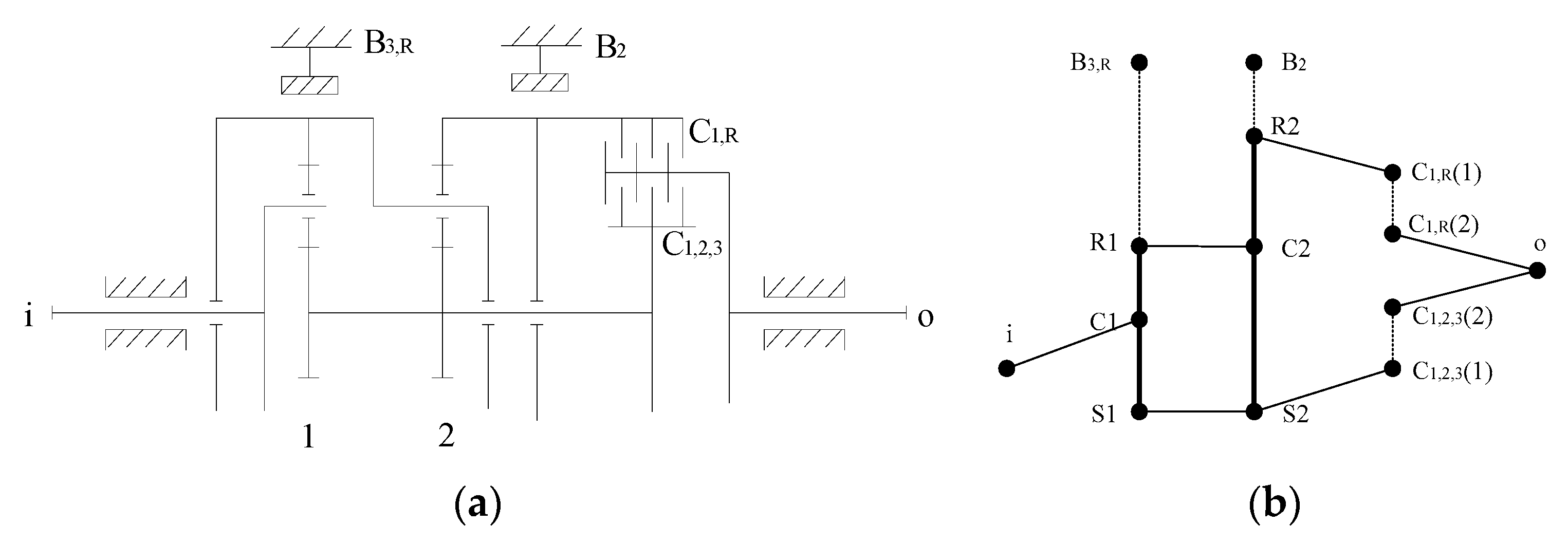
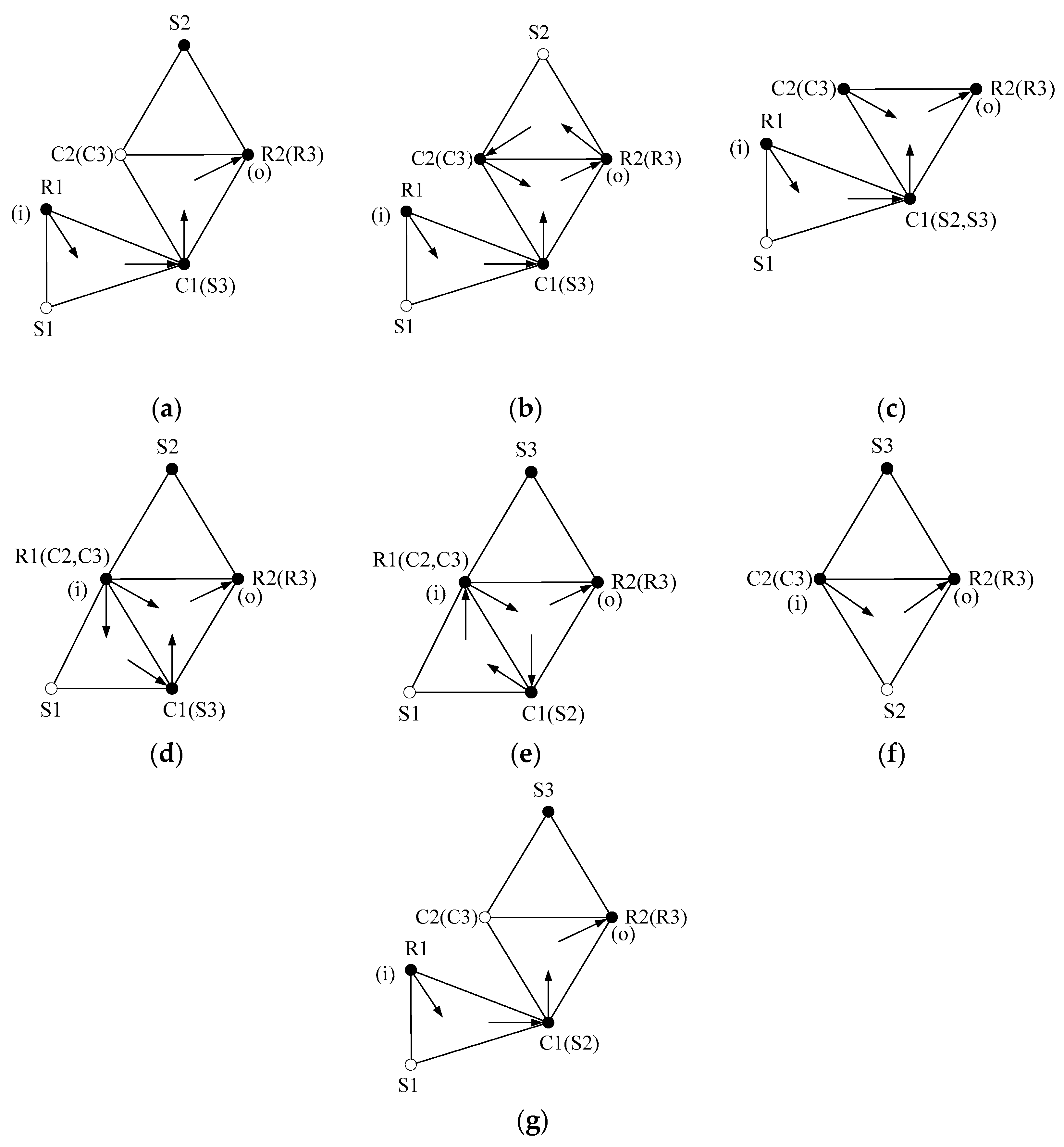
Figure 2a is a three-speed planetary gear transmission, and the overall performance analysis model is shown in
Figure 2b. In
Figure 2a, B represents the brake, C represents the clutch, i represents the input, and o represents the output. In
Figure 2b, R represents the ring, C represents the planetary carrier, and S represents the sun gear. In all subsequent figures, the meanings of these letters are the same. The dotted edge in
Figure 2b indicates that the connection relationship between components is manipulated by control elements.
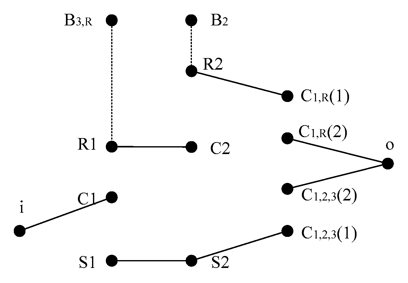
In the overall performance analysis model of the planetary gear mechanism, Q connected branches can be obtained by deleting the connecting edges between basic components of each planetary row and the connecting edges between vertices of the active and passive edges of the clutch. The degree of freedom of the planetary gear mechanism W = Q − k, where k is the number of planetary rows. From
Figure 2b, five connected branches can be obtained, as shown in
Figure 3. Therefore, in
Figure 2a, the degree of freedom of planetary gear transmission W = 5 − 2 = 3.
The clutch and brake were manipulated to obtain different gears of the automatic transmission while changing the topology ofthe planetary gear transmission. Therefore, by describing the working process of shift control components as a topological transformation of graph theory models, a shift topological transformation model of planetary gear transmission is established. According to the engagement of control elements, on the basis of the overall performance analysis model, the analysis model of each gear can be obtained. The state table of control elements for the planetary gear transmission in
Figure 2a is shown in
Table 1, and the analysis model of each gear is shown in
Figure 4. In
Table 1, black circle indicates that control element is in the engaged state.
2.1. Motion Analysis of Automatic Transmission
The motion analysis of an automatic transmission mainly includes the degree of freedom of automatic transmission, the calculation of the transmission ratio in each gear, and the rotational speed of components in each gear. The degree of freedom is related to the control of shifting components, and the transmission ratio is an important indicator for evaluating the transmission performance ofan automatic transmission, which is directly related to the driving comfort and fuel economy of the car.
The motion analysis model of each gear of an automatic transmission can be obtained by deleting the connection edges between basic components of each planetary row in
Figure 4.
- (1)
Motion characteristic matrix
The motion characteristic matrix
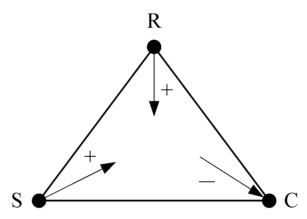
describes the component motion relationship of each planetary row. The single-star planetary row satisfies the motion relationship:
The double-star planetary row satisfies the motion relationship:
For a transmission consisting of k single-star planetary rows, its motion characteristic matrix is
In the formula, , , …, are the characteristic parameters of each planetary row, respectively.
- (2)
Connection matrix
Connection matrix is the matrix describing the component connection relationship of each planetary row. If one of the two connected components is marked as 1, the other is marked as −1, and other components are marked as 0. Then, each two connected components will form a row vector containing only 1, −1, and 0, and the resulting matrix is called a connection matrix.
- (3)
Gear matrix
Gear matrix (I = 1, 2, 3, …) is a matrix representing the brake and clutch engagement state of an automatic transmission in each gear. When the brake is engaged, the brake component is marked as 1; when the clutch is engaged, one of the two constant velocity components is marked as 1, the other is marked as −1, and other components are marked as 0. The last line of the gear matrix is the input vector, and the input component is marked as 1; the others are 0.
The transmission composed of
k planetary rows satisfies the following motion equation:
The speed of each component of an automatic transmission and the transmission ratio of each gear can be obtained by solving Formula (4).
2.2. Moment Analysis of Automatic Transmission
The mechanical transmission part of an automatic transmission is a key part of the power transmission, so the stress situation of each component has a significant impact on the working performance and service life of an automatic transmission. The mechanical analysis of an automatic transmission is aimed at analyzing the applied torque of each component, mainly including the external torque applied to the components and the internal torque suffered by the interaction between planetary rows. When conducting moment analysis, the influence of friction between components is ignored, and it is assumed that each component rotates at a uniform speed without considering the influence of inertia torque.
In
Figure 4, by deleting the connection edges between the basic components of each planetary row, the connection edges between the vertices of active and passive edges of the engaged clutches, and the vertices of disengaged clutches, the moment analysis model of each gear of an automatic transmission can be obtained.
- (1)
Moment characteristic matrix
The moment characteristic matrix
describes the component moment relationship of each planetary row. The single-star planetary row satisfies the moment relationship:
The double-star planetary row satisfies the moment relationship:
For a transmission consisting of k single-star planetary rows, its moment characteristic matrix is
In the formula, , , …, are the characteristic parameters of each planetary row, respectively.
- (2)
Independent member matrix without external force
The independent member matrix without external force (i = 1, 2, 3, …) is a matrix representing the stress state of each independent member without external force. The independent member without external force is not an input and output member, and it is not a braking member. The independent member without external force is recorded as 1, the others are recorded as 0, and the final matrix is called the independent member matrix without external force.
- (3)
Moment input matrix
Record all input members as 1 and others as 0 to obtain the moment input matrix (i = 1, 2, 3, …).
A transmission composed of
k planetary rows satisfies the following torque equation:
Solving Formula (8) can provide the component moment of an automatic transmission under each gear.
2.3. Power Flow and Efficiency Analysis of Automatic Transmission
The power transmission process ofan automotive automatic transmission is affected by factors such as gear meshing, oil droplet splashing, bearing friction, and air resistance, which can cause a certain amount of power loss. The greater the loss, the lower the power transmission efficiency and the poorer the fuel economy. When calculating efficiency in this article, only the power loss caused by gear meshing is considered, while other factors are ignored.
- (1)
Power flow analysis
During the power transmission process, there may be situations where the power transmitted by components is greater than the input power. This phenomenon is due to the formation of a closed power circuit inside the gear mechanism, known as cyclic power. This phenomenon will reduce transmission efficiency and increase meshing power loss, so it is important to avoid choosing solutions that are significantly affected by this phenomenon. Determining the power transmission path of automatic transmission through power flow analysis is beneficial for distinguishing and observing cyclic power and plays an important role in accurate efficiency evaluation.
From the motion and moment analysis of an automatic transmission, the rotational speed and torque of each component can be obtained, respectively; thus, the power flow of automatic transmissions can be determined. If the component power is positive, it is input power; if the component power is negative, it is output power. The power flow diagram of a planetary row is shown in
Figure 5. The arrow inward represents the input power and the arrow outward represents the output power.
- (2)
Efficiency analysis
Transmission efficiency is an important indicator for evaluating the performance of planetary gear trains. According to experience, the transmission efficiency of forward gear should not be less than 0.925, while for gears such as reverse gear and first gear that are relatively less frequently used, the transmission efficiency should be relaxed to not be less than 0.87.
At present, there are many methods to determine planetary gear transmission efficiency. In this paper, the transmission ratio method is used to calculate transmission efficiency.
For a transmission composed of
k planetary rows, the efficiency of each gear is
In Formula (11), is the transmission efficiency of a planetary row. Denote the transmission efficiency of an external meshing gear pair as and the transmission efficiency of an internal meshing gear pair as ; then, for a single-star planetary row and for a double-star planetary row . Usually, , .
In addition, in Formula (11),
3. Performance Analysis Example of Automatic Transmission
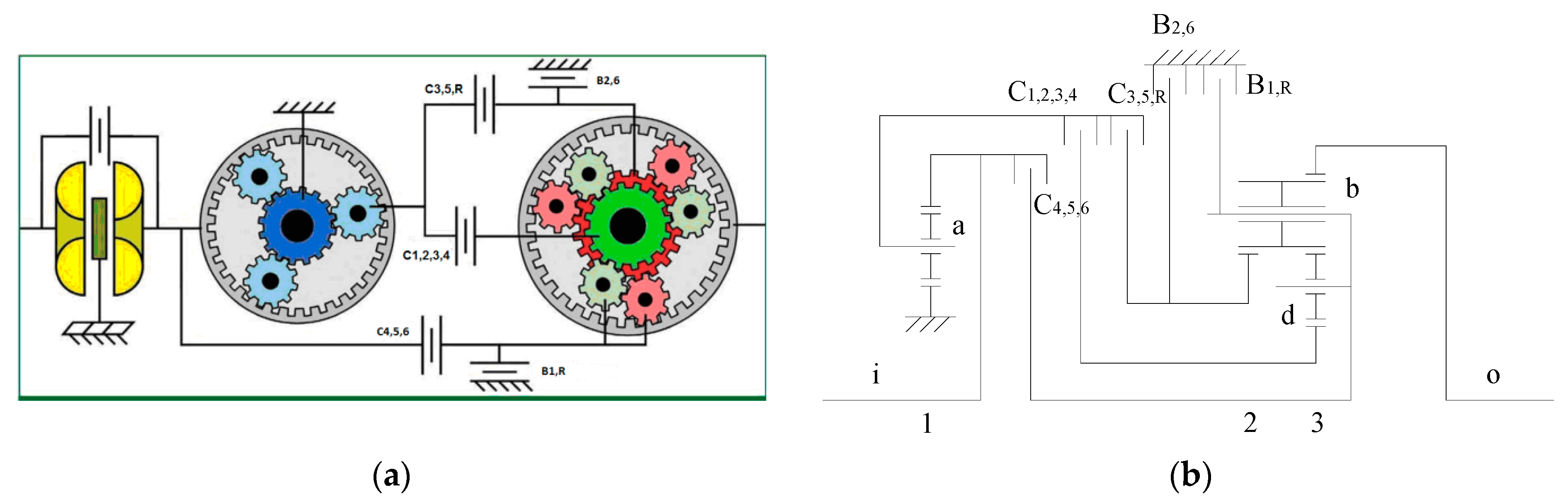
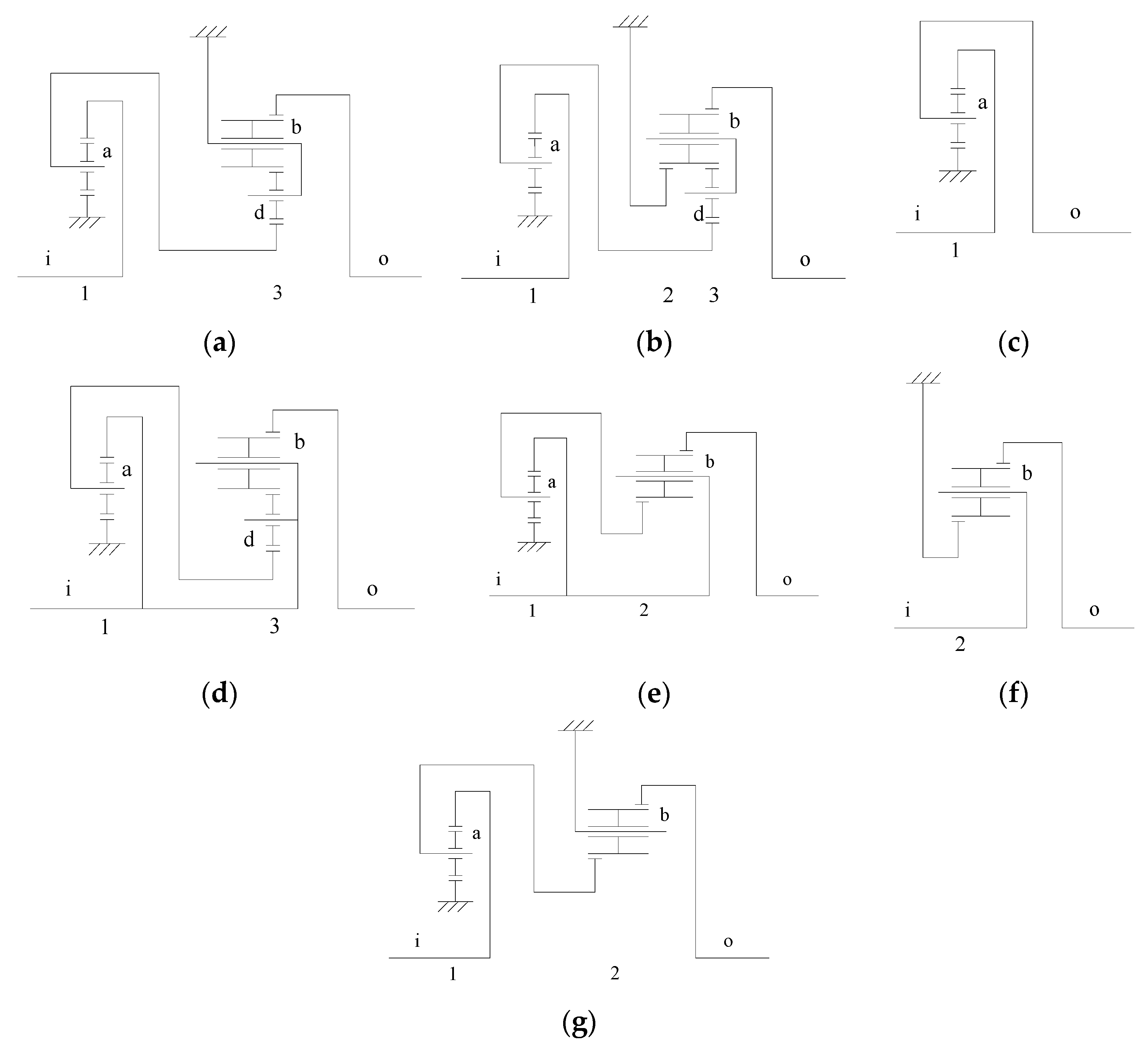
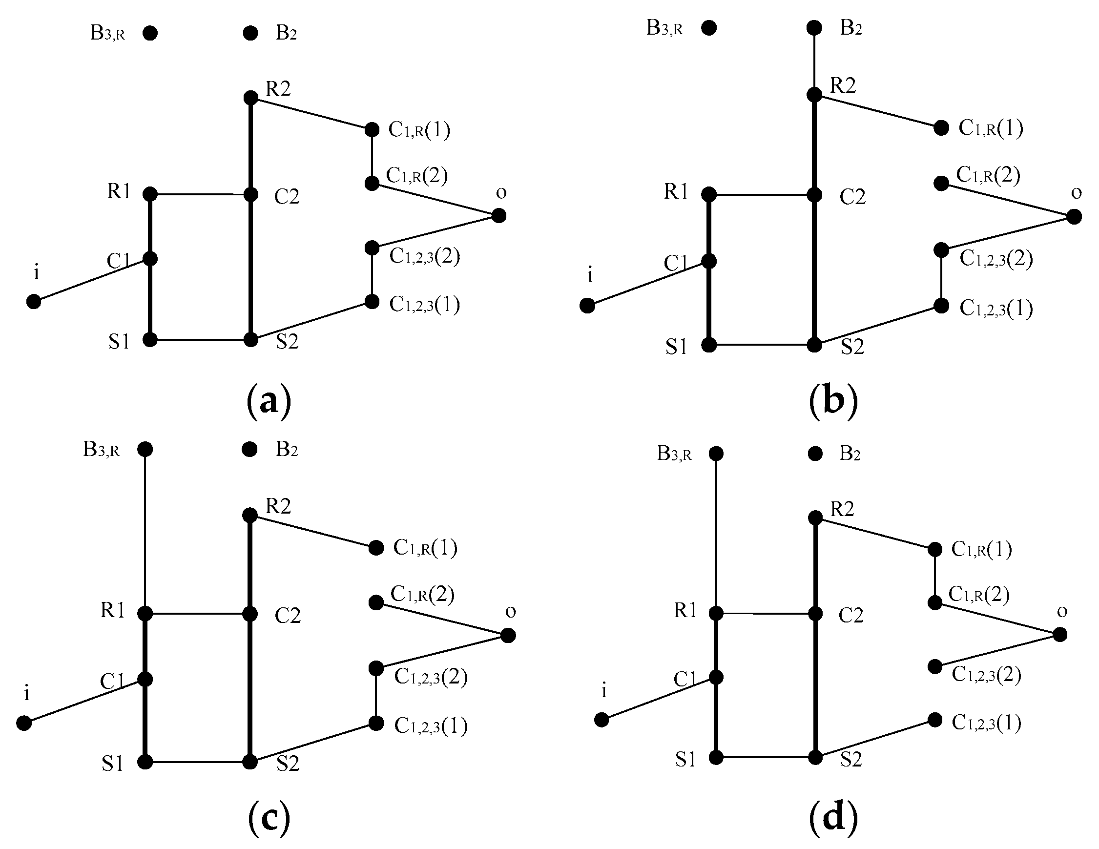
Figure 6 is a schematic diagram of a 6HP26 automatic transmission developed by the German company ZF. The planetary wheel of the first planetary row is represented by a. The long planetary wheel and short planetary wheel of the third planetary row are represented by b and d, respectively. In
Figure 6a, each gear is distinguished by a different color. A 6HP26 automatic transmission will be taken as an example to analyze its motion, moment, power flow, and efficiency.
A 6HP26 automatic transmission can realize four reduction gears, two overdrive gears, and one reverse gear. The status table of control elements is shown in
Table 2. The transmission diagram of a 6HP26 automatic transmission in each gear is shown in
Figure 7, and the gear ratio of each gear is shown in
Table 3. In
Table 2, black circle indicates that control element is in the engaged state.
The numbers of teeth of the sun gear, ring gear, and planetary gear for the first planetary row of a 6HP26 automatic transmission are , , and , respectively; the numbers of teeth of the sun gear, ring gear, and planetary gear for the second planetary row are , , and , respectively; and the numbers of teeth of the sun gear, ring gear, long planetary gear, and short planetary gear for the third planetary row are , , , and , respectively. The input speed is , and the input moment is .
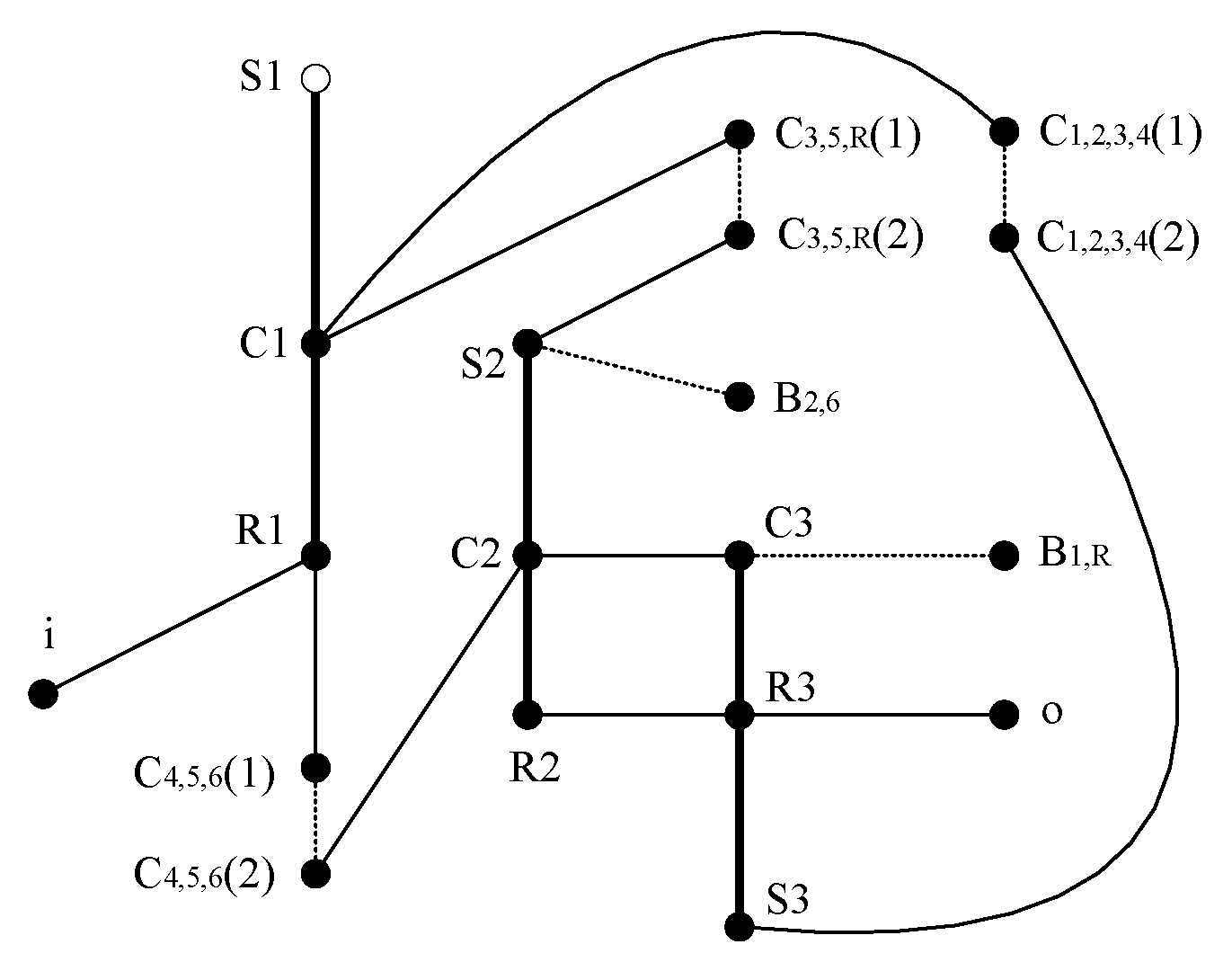
The performance analysis model of a 6HP26 automatic transmission is shown in
Figure 8. The dotted line edge in
Figure 8 indicates that the connection between components is controlled by control elements.
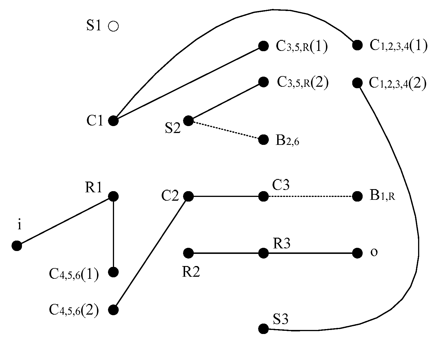
In
Figure 8, six connected branches can be obtained by deleting the connecting edges between basic components of each planetary row, and the connecting edges between vertices of the active and passive edges of the clutch, as shown in
Figure 9. The degree of freedom of 6HP26 automatic transmission W = 6 − 3 = 3.
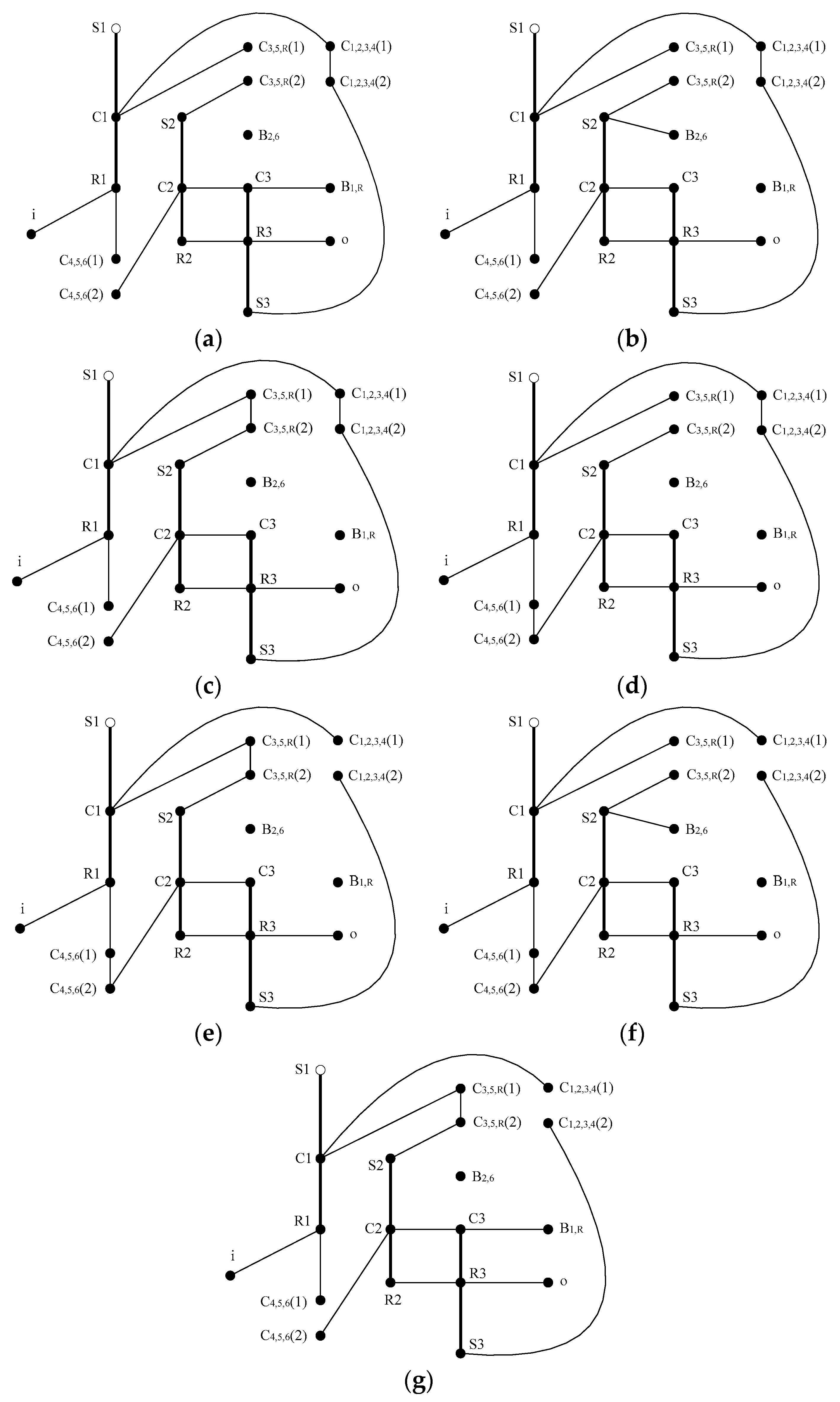
According to the engagement of control elements, the analysis model of each gear can be obtained, as shown in
Figure 10.
3.1. Motion Analysis
The motion analysis model of each gear of a 6HP26 automatic transmission can be obtained by deleting the connection edges between basic components of each planetary row in
Figure 10.
Components of the first, second, and third planetary row are numbered 1, 2, …, 9 in the order of sun gear, ring, and planet carrier, and the rotational speeds of the components are , , …, , respectively. The characteristic parameters of the first, second, and third planetary row are , , .
Motion characteristic matrix of a 6HP26 automatic transmission:
The transmission ratio and component speed of a 6HP26 automatic transmission at each gear can be obtained from the following equation, as shown in
Table 4 and
Table 5, respectively.
3.2. Moment Analysis
In
Figure 10, by deleting the connection edges between basic components of each planetary row, the connection edges between vertices of active and passive edges of the engaged clutches, and the vertices of disengaged clutches, the moment analysis model of each gear of a 6HP26 automatic transmission can be obtained.
Components of the first, second, and third planetary row are numbered 1, 2, …, 9 in the order of sun gear, ring, and planet carrier, and the moments of the components are , , …, , respectively.
Moment characteristic matrix of a 6HP26 automatic transmission:
Independent member matrix without external force:
The component moment of a 6HP26 automatic transmission at each gear can be obtained from the following equation, as shown in
Table 6.
3.3. Power Flow and Efficiency Analysis
From
Table 5 and
Table 6, the component speed and moment can determine the power flow. A power flow diagram of a 6HP26 automatic transmission at each gear is shown in
Figure 11.
According to the transmission ratio of each gear in
Table 4, the efficiency of a 6HP26 automatic transmission at each gear can be obtained from Formula (9), as shown in
Table 7.
3.4. Discussion
In the motion analysis of a 6HP26 automatic transmission, we can observe from
Table 4 that the first, second, third, and fourth gears of a 6HP26 automatic transmission are deceleration gears, and the transmission ratio decreases sequentially; the fifth and sixth gears are growth gears; and the reverse gear ratio is negative. From
Table 5, we can observe that the rotational speeds of 6HP26 automatic transmission components S1, R1, and C1 remain unchanged in each gear, while the rotational speeds of other components vary in each gear.
In the moment analysis of a 6HP26 automatic transmission, we can observe from
Table 6 that the component torque of a 6HP26 automatic transmission varies in various gears, which can be positive, negative, or 0.
In the power flow and efficiency analysis of a 6HP26 automatic transmission, we can observe from
Table 7 that the efficiency is low in first gear, second gear, and reverse gear, because it is series connection in these gears. The other gears are connected in parallel, so the transmission efficiency is higher.
In addition, the author also compared the motion, torque, and efficiency analysis ofa 6HP26 automatic transmission with the analysis results in the existing literature [
3,
5,
23,
30]. The results showed that the speed, torque, power flow, and efficiency values of each gear foran automatic transmission calculated using this method were accurate, and the method used in this article was easier to achieve through computer programming, making it possible to automate the design and analysis of planetary gear transmissions.


