Abstract
The satellite navigation system of Unmanned Aerial Vehicles (UAVs) is susceptible to external interference in a complex environment, resulting in the loss of their own geodetic coordinate information. A spatial registration method for multi-UAVs based on a cooperative platform in a geodesic coordinate information-free environment is proposed to solve this problem. The mutual observation information between UAVs is approximated by the observation information of the cooperative platform. Indirect observation information of the target can be obtained on account of mutual observation. On the basis of this, a close-range spatial registration algorithm without the geodetic coordinate information of UAVs is designed by means of the right-angle translation method. Finally, the Kalman filtering technique is used to track maritime targets. In this paper, the proposed method is verified by a simulation experiment and a practical experiment. The proposed method is 90% effective in reducing systematic errors. The tracking accuracy after alignment is significantly better than that of the original trajectory.
1. Introduction
Unmanned Aerial Vehicles (UAVs) play an increasingly important role in the field of target detection with the continuous development of UAVs. Multi-UAV collaboration can further improve target tracking accuracy, but a series of problems, such as error registration and filter tracking, need to be solved.
Spatial registration is the process of observing the same target by different sensors and transforming the observed information into the same coordinate system to estimate the sensor measurement error and the attitude error of the moving platform. The spatial registration of the UAV is generally included in the target tracking process. It is difficult to estimate the accurate position of the target without spatial registration. When a UAV observes a target, the error in the observation information mainly comes from two types of error: sensor observation error and platform attitude error. Existing spatial registration algorithms include real-time quality control (RTQC) [1], least squares (LS) [2,3], maximum likelihood estimation (ML) [4], exact maximum likelihood estimation (EML) [5], etc. Currently, there are two main methods for spatial registration by the type of observation target. The first one is to perform spatial registration directly through the observed target. This method performs spatial registration through the observation of the same target by multiple sensors, and generally requires certain external information, such as the high-precision geodetic coordinates of the platform itself or the mutual observation information between platforms. The literature [6] proposes a spatial registration method that minimizes the estimation of the common target position by neighboring sensors, which is applicable to real-time distributed filtering. However, it needs to measure the relative distance between neighboring sensors to provide mutual observation information, which increases the sensor burden. The literature [7] proposes a method for spatial registration of a single sensor using batch nonlinear least squares estimation, which is shown to be statistically valid by the evaluation of the Clamero lower bound, but the method requires high-precision satellite coordinates of the sensor. Lu Z. and Zhu M. et al. [8] proposed an iterative design spatial registration algorithm based on expectation maximization (EM), but the model is too ideal and far from engineering applications. Li D et al. [9] designed a spatial registration algorithm based on exact least squares for multiple dissimilar sensors, but the sensor data type and scenario environment are too simple. Pu W et al. [10] used a two-stage nonlinear least squares method to solve the spatial registration problem of asynchronous multiple sensors, but only the range and azimuth errors were analyzed, which is only applicable to a two-dimensional radar. Shang J et al. [11] used an exact great likelihood algorithm to achieve the spatial registration of two station coast radar systems based on noncooperative targets; the scenario posture is more realistic, but this method does not consider the attitude of the moving sensors and is only applicable in the two-dimensional plane. Lu X et al. [12] took the measurement error and attitude error of the sensors into account simultaneously. However, they did not consider the coupling of the sensor measurement error and the attitude error. In summary, the current spatial registration methods by direct observation of the target require additional information, such as platform geodesic coordinates or mutual observation information, to perform position alignment, and most of them only consider the sensor measurement error, ignoring the attitude error of the moving platform, which will also cause a large error in the measurement data. The second spatial registration method relies on a cooperative platform. This method relies on the priori information of the cooperative platform to firstly perform spatial registration, and then performing observation and data fusion of the target. Drummond O.E et al. [13] proposed an error estimation method for multiple passive sensors using cooperative targets, but it requires a common coordinate system and is only applicable to a linear system. Zhu H et al. [14] designed an attitude solution model based on the combination of photoelectric sensors and MEMS-IMU by observing auxiliary beacons, which can be treated as a cooperative platform. Zhao Y et al. [15] used optical sensors to compensate for the attitude error of the vehicle but did not consider the measurement error of the sensors. Most of the current spatial registration algorithms based on cooperative platforms only achieve accurate estimations of the attitude of the platform, but few research studies consider the sensor measurement error.
Target tracking is a technique used to estimate the state of a target based on measurement information from sensors, so spatial registration is a prerequisite to perform target tracking. The filter is the essence of the target tracking algorithm. The Kalman filter (KF) [16] was first proposed to solve linear problems. For nonlinear problems, the extended Kalman filter (EKF) [17,18] was first proposed, but due to its weak treatment of strongly nonlinear problems, the traceless Kalman filter (UKF) [19,20], the volumetric Kalman filter (CKF) [21,22], and the particle filter (PF) [23] appeared one after another. Although they have higher accuracy on nonlinear problems, the computational complexity is correspondingly much higher. Recently, the probabilistic hypothesis density filter (PHD) [24,25,26] has been used in multi-target tracking problems with multi-sensor bias, which has become a hot problem recently, but it is mostly applied only in the two-dimensional plane, and it also suffers from the same high computational complexity, which makes it difficult to accomplish the task of real-time tracking. All of the above are methods based on data information [27]. In addition, the UAV target detection and tracking method based on computer vision has gradually become popular [28].
When locating and tracking maritime targets in the maritime environment, UAVs generally use satellite navigation systems to provide their own high-precision geodetic coordinate information to complete the tracking of targets [29,30,31], but in the complex maritime environment [32,33,34], especially in the battlefield environment, the fragile satellite navigation system is susceptible to interference from threats such as electromagnetic pulse and intentional deception, which affects maritime target tracking and affects the accuracy of target tracking. Tang C et al. [35] proposed a multi-source UAV cluster collaborative positioning method using information geometry, which realizes the self-positioning problem of UAVs in non-ideal environments.
Since both current abatement methods have their own limitations and there are few studies on multi-UAV spatial registration in a geodesic coordinate information-free environment, this paper designs a spatial registration method for multi-UAVs based on a cooperative platform in a geodesic coordinate information-free environment. Firstly, with the aid of a cooperative maritime platform that can move its position at any time, the mutual observation information among UAVs is approximated by the observation of UAVs in close proximity. Then, the right-angle translation method is used to obtain indirect observation information of UAVs on maritime targets based on the mutual observation information. Finally, an error estimation method is designed by combining direct and indirect observation information of UAVs on maritime targets. Accurate tracking of the maritime target is realized using the filtering algorithm.
The remainder of the paper is organized as follows: Section 2 describes the problem of spatial registration and introduces the general environment. Section 3 proposes the target tracking method, including mutual UAV observation information based on a cooperative platform, the spatial registration method, and the maritime target tracking method. In Section 4, experimental verification is provided. Finally, conclusions are drawn in Section 5.
2. Problem Description
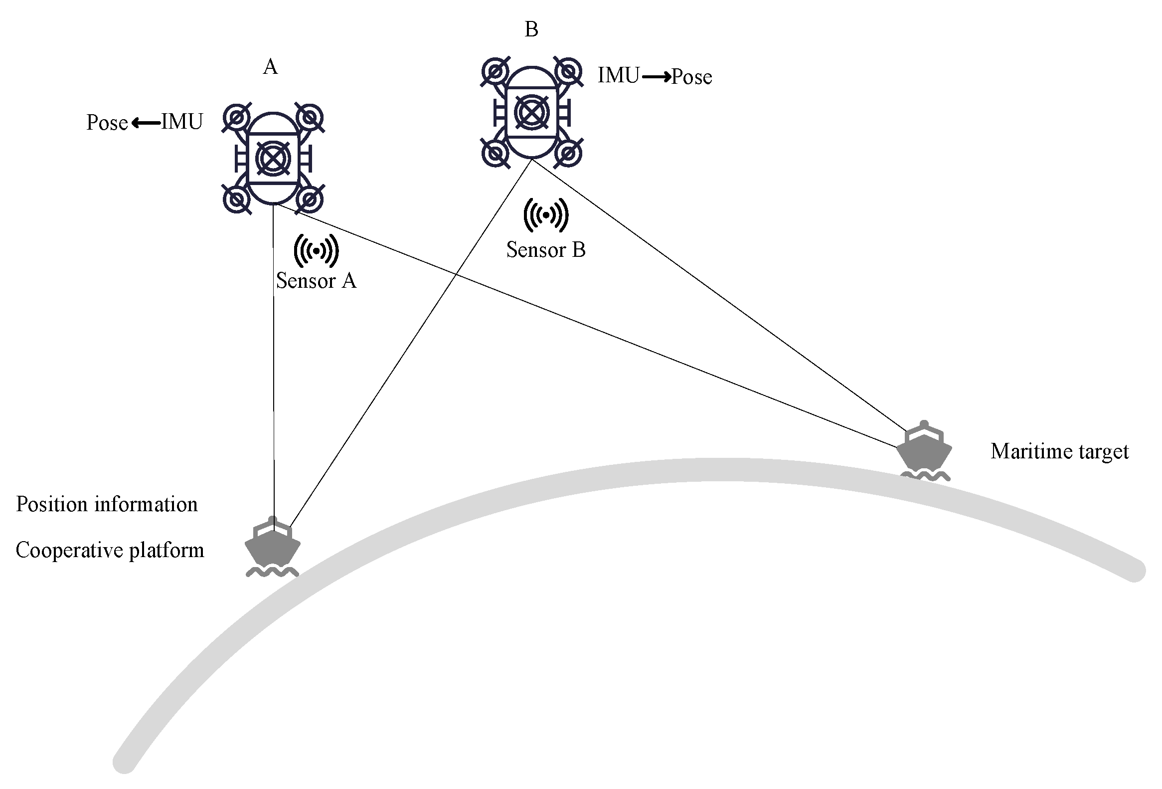
At the moment k, the observation information (distance, azimuth, elevation) of UAV A and B to cooperative platform C and the sea target T are , , , . Attitude information (yaw, pitch, roll) of the platform’s own inertial guidance output is , . The cooperative platform provides its own accurate geodetic coordinate information , and the posture is shown in Figure 1.
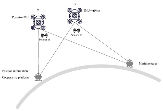
Figure 1.
Schematic diagram of the situation.
The observation information of UAV sensors usually consists of three parts, true value , systematic error of sensor measurement , and random error of sensor measurement , so the observation information of UAVs A and B on the target and the cooperative platform are related as follows:
The attitude information of the UAV is also composed of true value , sensor measurement systematic error , and sensor measurement random error , so the attitude information of UAVs A and B is related as follows:
The tracking of the target directly from raw data will produce large errors, especially as the influence caused by systematic errors among them is difficult to eliminate, so a method is needed to estimate and reduce the systematic errors of observation data and attitude information without the geodetic coordinates of the observation platforms, so as to complete the accurate tracking of targets at sea.
3. Target Tracking Method
The target tracking method includes mutual observation information based on a cooperative platform, the spatial registration method, and the maritime target tracking method.
3.1. Mutual Observation Information Based on a Cooperative Platform
3.1.1. Mutual Observation Information
The mutual observation information among UAVs is obtained by approximating the observation information of UAVs on a cooperative platform. The cooperative platform is treated as a fusion center. The positions of the UAVs, the cooperative platform, and the maritime target are unified into a local geographic reference system under the fusion center.
The position of the cooperative platform under the local geographic coordinate system centered on platform A is
where is the transformation of the unstable carrier coordinate system into the stable carrier coordinate system and the expression is
is the conversion from spherical to Cartesian coordinates and the expression is
Due to the close proximity of the cooperative platform and the UAV, the influence of the curvature of the Earth on the coordinate transformation can be ignored, so the position coordinate of UAV A in the local geographic coordinate system under the fusion center is approximated as
Similarly, the position coordinate of UAV B in the local geographic coordinate system under the fusion center is
So far, the positions of UAVs A and B have been unified into the same coordinate system.
Combining Equations (10) and (11), the position of UAV B in the local geographic coordinate system of UAV A can be approximately obtained
Therefore, the observation information from UAV A to UAV B is
where is the conversion from Cartesian to spherical coordinates and the expression is
3.1.2. Error Analysis
The Earth coordinates of UAV A and B and the cooperative platform are , , . The transformation matrix of the earth coordinate system to the local geographic coordinate system is .
The true value of the local geographic coordinates of UAV B at the center of UAV A is
The approximation of the local geographic coordinates of UAV B in the center of UAV A is
Comparing Equations (15) and (16), we can obtain the observation information of UAV A on UAV B so that the approximation is approximately equal to the true value, then we need to ensure that
This means that the following two conditions are satisfied: (1) the distance between UAVs A and B cannot be too far; (2) the distance between UAV B and the cooperative platform cannot be too far.
3.2. The Spatial Registration Method
3.2.1. Indirect Observation Information of the Target Based on Mutual Observation
Indirect observation information of the target based on mutual observation can be obtained by means of multiple UAVs. In this paper, we use two UAVs as an example.
Based on the mutual observation information of UAV A to UAV B in Equation (16), we can obtain the observation information of UAV A to the target through UAV B. The position of the target in the local geographic coordinate system centered on UAV A is
3.2.2. Spatial Registration Based on the Right-Angle Translation Method
The location of the target in the local geographic coordinate system centered on UAV A is obtained from the direct observation data of the target at sea by UAV A, which is denoted as .
Assuming that both the sensor observation information and the platform attitude information are true, we can obtain
Equation (19) can be extended as follows:
Substitute Equations (10)–(12) into Equation (20):
Considering the true value as a function of measured value and error value, the sensor measurement information and the attitude information are subjected to a first-order Taylor expansion at their measured values. Since systematic and random errors of the measured values are in small quantities compared to true and measured values, a higher order can be approximately ignored and only the first-order term is retained.
Let
Equation (21) can be expanded to
Substitute Equations (1)–(6) into Equation (24); simplification gives
Organize Equation (25) and let
So far, the pseudo-measurement equation to eliminate sensor measurement systematic errors and attitude systematic errors is established as
The specific derivation of this part is shown in Appendix A.
With the development of various technologies, the sensor measurement error and its own attitude error generally change slowly, and the state equation used for spatial registration [36] is established as
where is state noise.
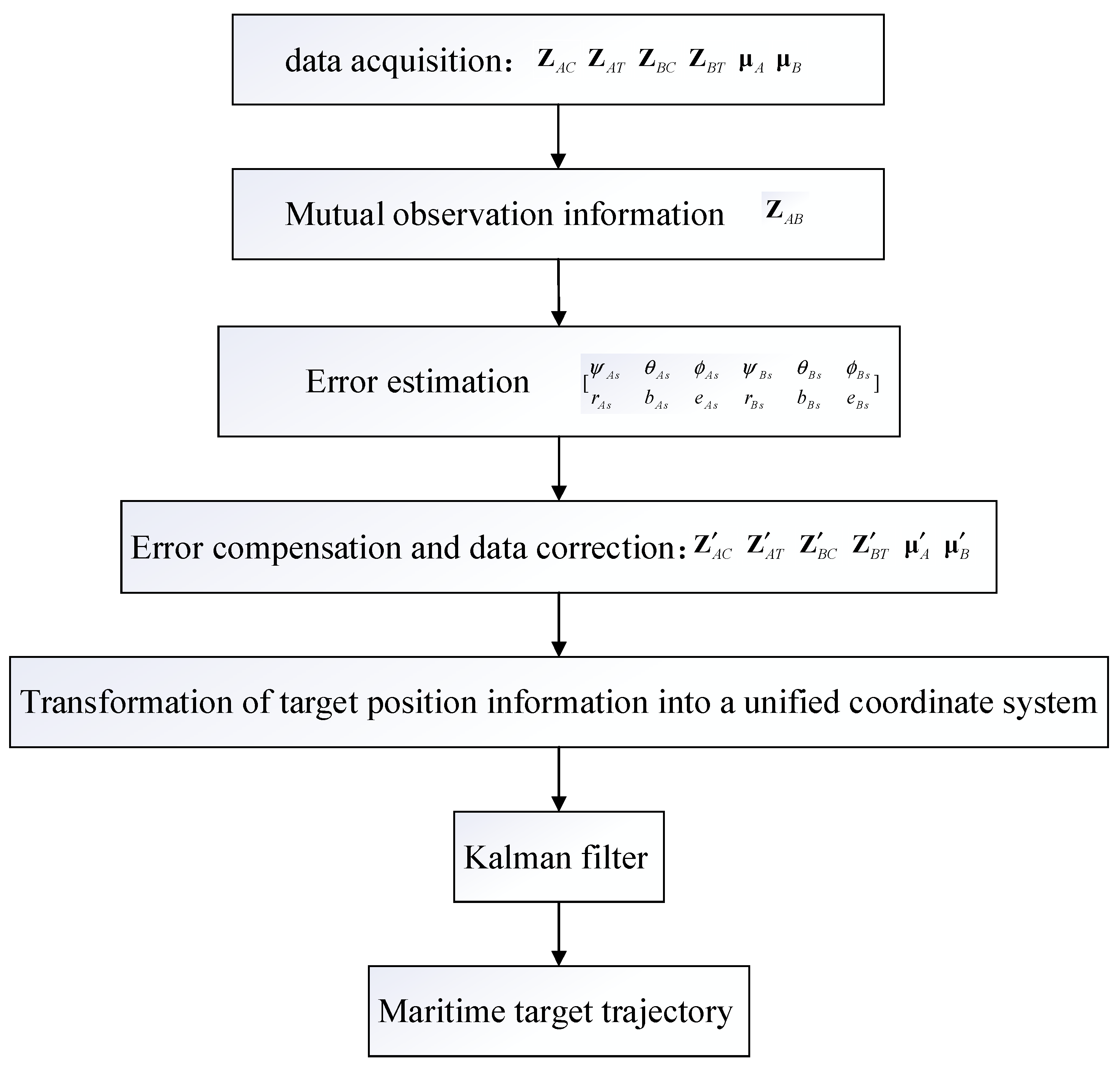
The specific process is shown in Figure 2.
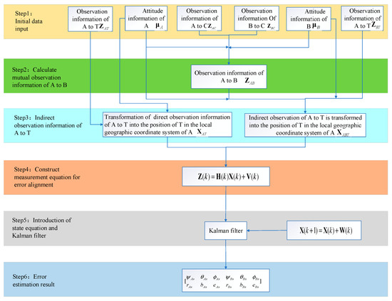
Figure 2.
Spatial registration method.
3.3. Maritime Target Tracking Method
According to the estimated systematic error in Equation (28), the systematic error in Equations (1)–(6) is reduced to obtain the observation information of UAVs A and B to the cooperative platform and the sea target T at the moment k, which are denoted as , , , . The attitude information of the platforms after inertial guidance compensation is and , respectively. The above has completed the estimation of sensor observation errors and platform attitude errors, and then the data are aligned and compensated. Next, we move to the tracking of the target at sea.
In order to fuse the observation information of the two UAVs, it is necessary to transform the observation information of both into a unified coordinate system, and the initial position of the cooperative platform is taken as the fusion center in this paper.
Two different tracking methods are designed according to the motion state of the cooperative platform: one is the tracking method when the cooperative platform is stationary, and the other is the tracking method when the cooperative platform is in motion.
When the cooperative platform is stationary, the fusion center is the position of the cooperative platform, and the geodetic coordinates of the cooperative platform are not required to transform observation information into a unified coordinate system at this time:
However, considering the effect of wind, currents, and other factors, it is difficult to keep the cooperative platform absolutely stationary in the real scenario. Therefore, the motion of the cooperative platform must be considered.
When the cooperative platform is in motion, the tracking and filtering fusion of the target directly using Equations (33) and (34) fails. It is necessary that the cooperative platform needs to send its own high-precision geodetic coordinate information in real time at the current moment to transform observation information into a unified coordinate system.
Transform the target position into geodetic coordinates:
where is the transformation of local geographic coordinates to geodetic coordinates.
The target position is then transformed into a unified coordinate system based on the initial position information of the cooperative platform :
where is the transformation of geodetic coordinates into local geographic coordinates.
Combined with Kalman filtering to complete the localization and tracking of the target, the specific flow chart is shown in Figure 3.
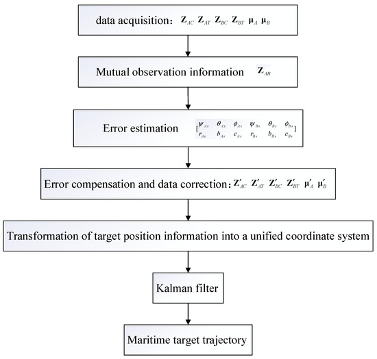
Figure 3.
Algorithm of sea target tracking based on spatial registration.
4. Experimental Verification
The following are a simulation experiment and practical experiment. Each section consists of a basic introduction and result.
4.1. Simulation Experiment
A simulation experiment is firstly conducted to verify the feasibility of the method.
4.1.1. Experimental Parameter Setting
To facilitate the display of the simulation experiment results, the initial position of the cooperative platform is used as a fusion center, and some parameters are set in a local geographic coordinate system centered on the fusion center. The data rate is set to 20 Hz. The initial geodetic coordinates of the cooperative platform are set to ; the coordinates of UAVs A and B in the local geographic coordinate system are and ; the standard deviations of the sensor error and attitude error of UAVs A and B are shown in Table 1 and Table 2, respectively. The root mean square error (RMSE) is used as error evaluation index.

Table 1.
Error characteristic of UAV A.
Table 2.
Error characteristic of UAV B.
Considering the real situation, it is difficult to keep the cooperative platform absolutely stationary. Therefore, to verify the error estimation and target tracking effect when the cooperative platform moves, the scenario is set as follows: The initial position of the marine target with the geodesic length and geodesic azimuth relative to the fusion center is 198,000 m and 0 m, respectively. Both the target and the cooperative platform move 2000 m in the direction of geodesic azimuth 0 within 200 s.
4.1.2. Simulation Experimental Result
Simulation experiments are conducted under the above parameters and scenario setting, and the experimental result is as follows.
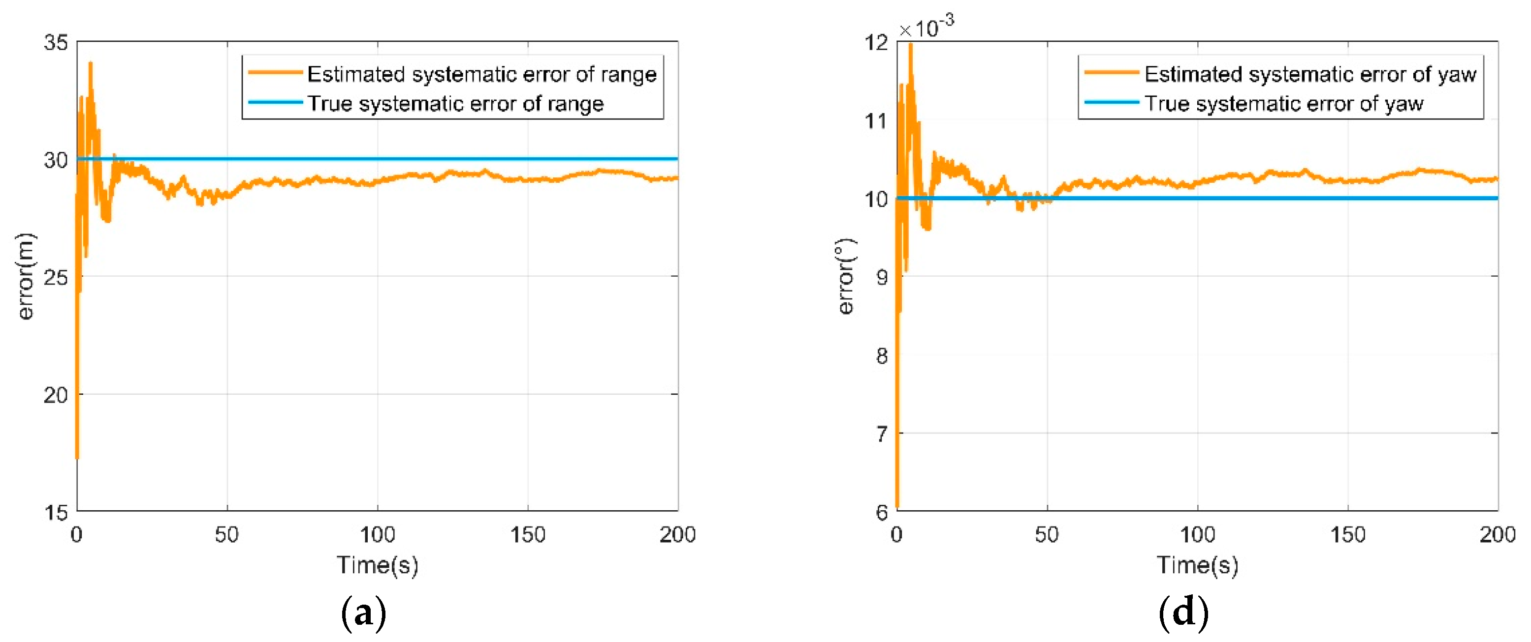
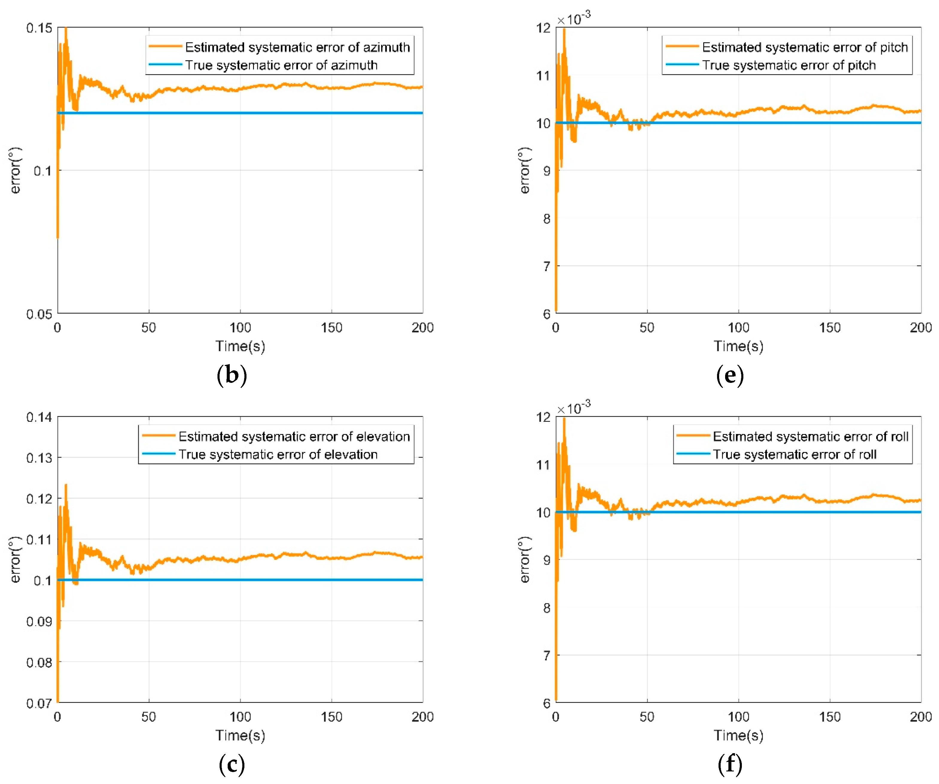
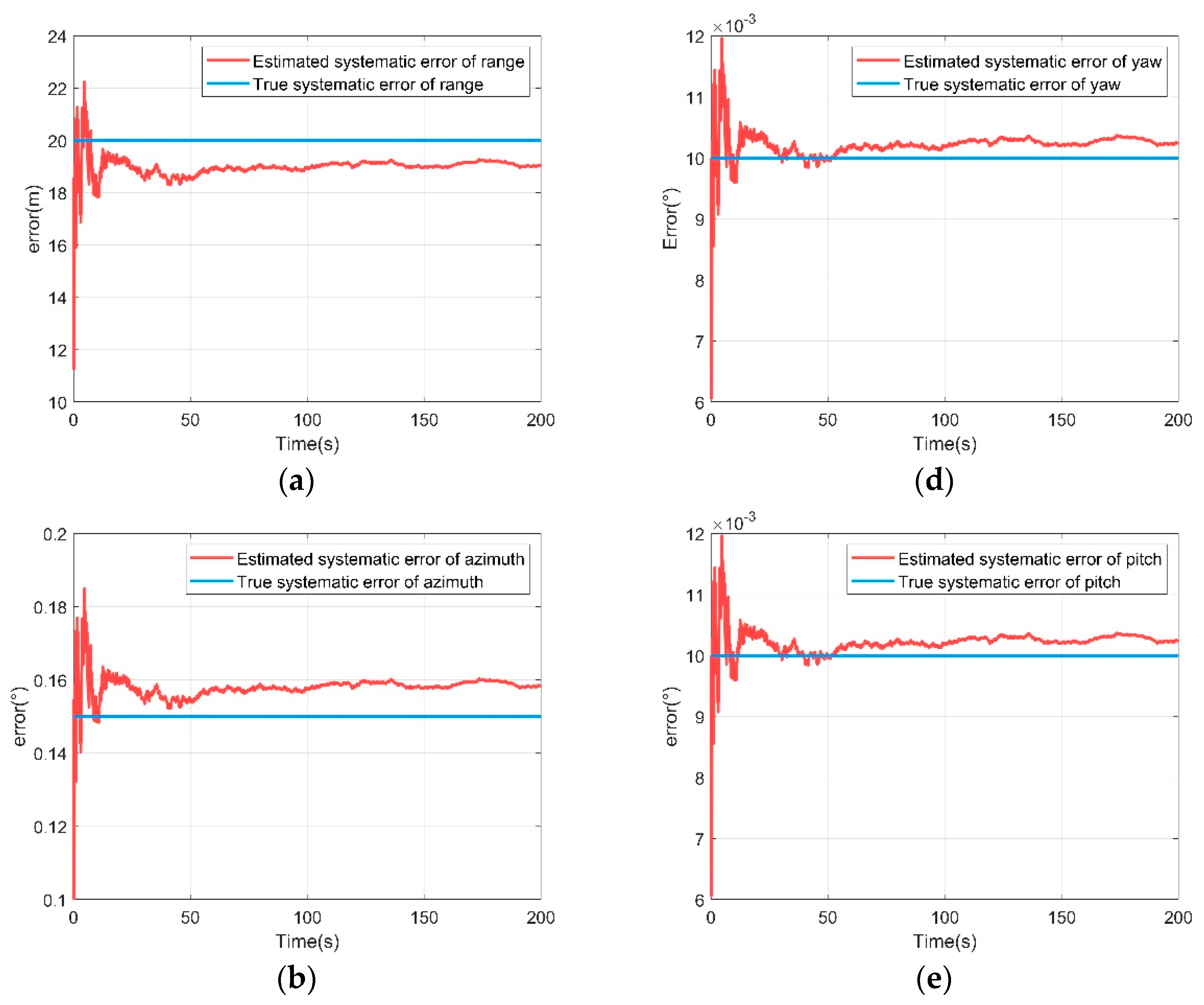
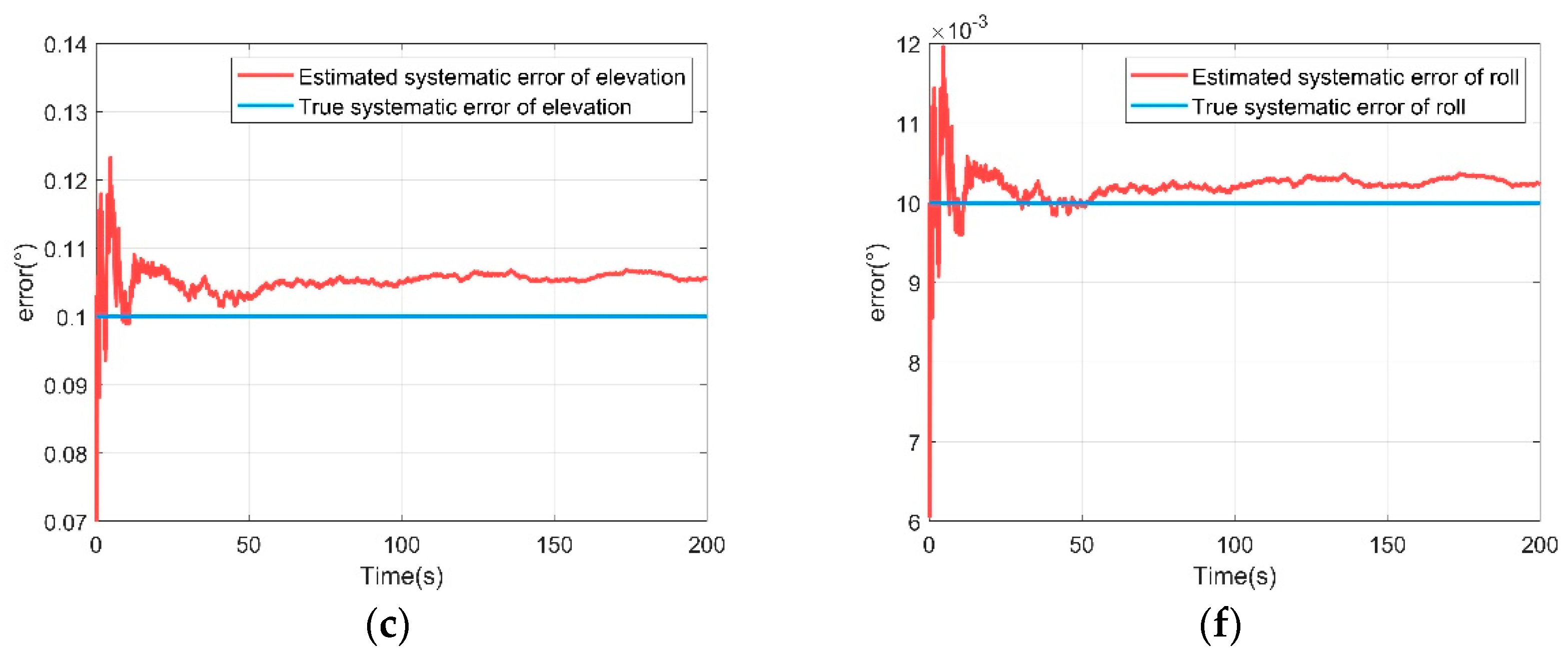
Figure 4 and Figure 5 show the results of sensor measurement systematic error and attitude systematic error estimation for UAVs A and B, respectively. As can be seen from Figure 4 and Figure 5, the results of the algorithm all converge to the set systematic error values quickly. Before 10 s, the initial value deviates from the true value, resulting in a large jitter. But at around 10 s they all converge gradually and remain stable, indicating the effectiveness of the proposed algorithm.
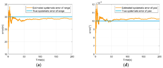
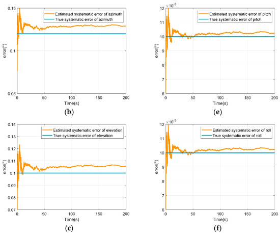
Figure 4.
Systematic error estimation of UAV A. (a) Range systematic error estimation of UAV A; (b) azimuth systematic error estimation of UAV A; (c) elevation systematic error estimation of UAV A; (d) yaw systematic error estimation of UAV A; (e) pitch systematic error estimation of UAV A; (f) roll systematic error estimation of UAV A.
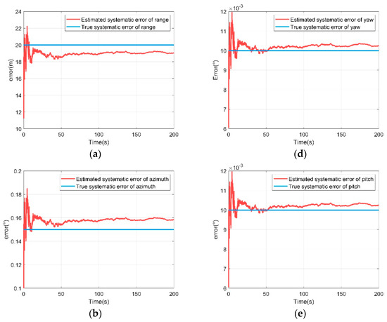
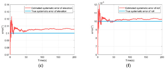
Figure 5.
Systematic error estimation of UAV B. (a) Range systematic error estimation of UAV B; (b) azimuth systematic error estimation of UAV B; (c) elevation systematic error estimation of UAV B; (d) yaw systematic error estimation of UAV B; (e) pitch systematic error estimation of UAV B; (f) roll systematic error estimation of UAV B.
Table 3 shows the root mean square error of the sensor measurement estimation systematic error and attitude estimation systematic error for UAVs A and B, respectively. From Table 3, it can be seen that the abatement rates of the sensor measurement systematic error and attitude systematic error of UAVs A and B are basically above 90%.
Table 3.
Root mean square error of systematic error estimation.
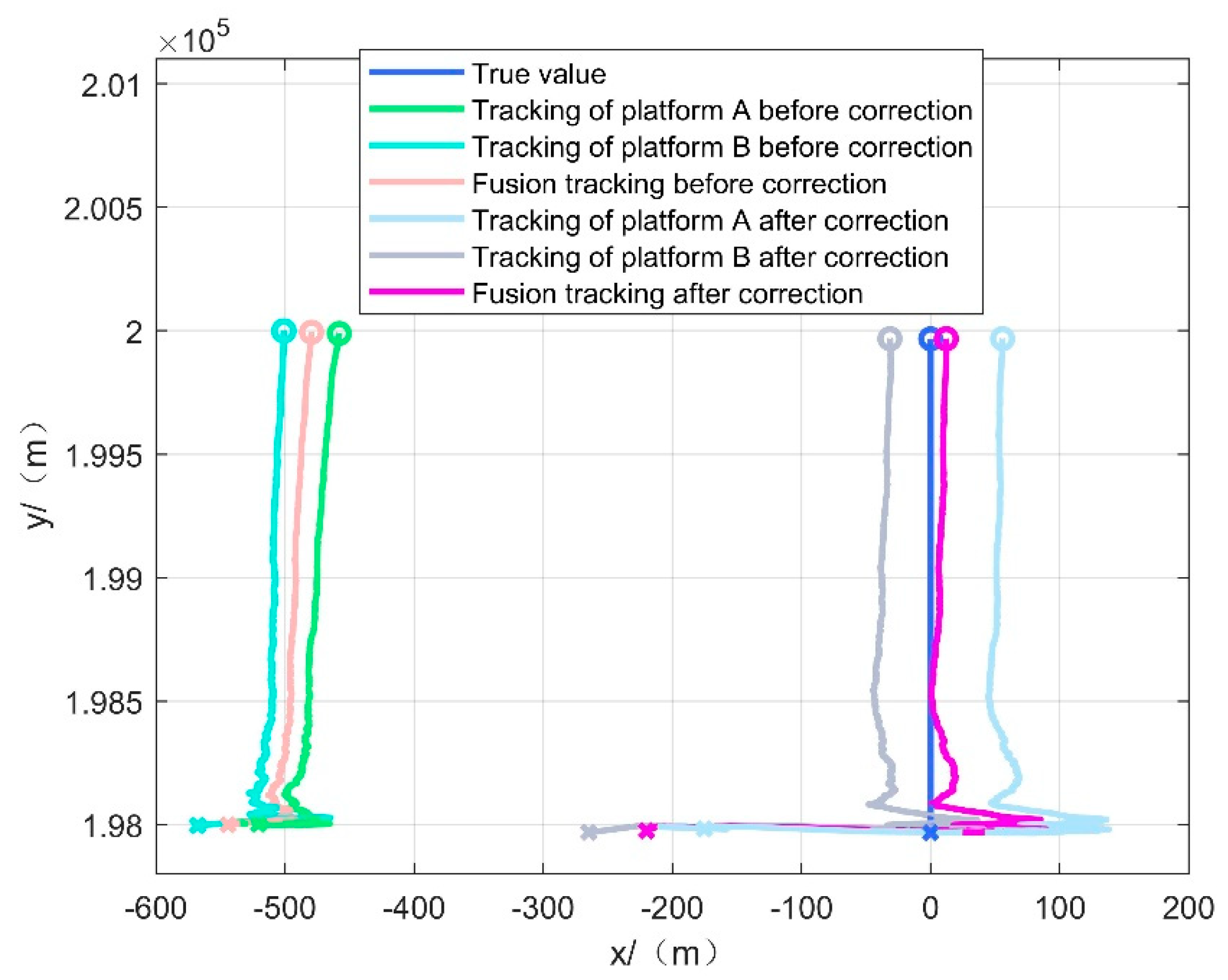
Figure 6 shows the effect of tracking the maritime target after spatial registration when the cooperative platform is moving, and Table 4 shows the root mean square error of the X and Y directions as well as position estimation for different tracking methods in scenario one.

Figure 6.
Tracking effect of scenario one.
Table 4.
Position estimation error for scenario one.
As shown in Figure 6 and Table 4, the corrected single-platform and multi-platform fusion tracking effects are better than that of the uncorrected single-platform and multi-platform fusion. Due to sensor systematic errors and attitude systematic errors, the uncorrected tracking trajectories all deviate from the true value of the target motion trajectory, while the corrected single-platform tracking effect has been improved compared with the uncorrected one. However, there are still some deviations due to the coordinate transformation error and error estimation error, and the tracking accuracy is further improved by the fusion of the unified coordinate system of the cooperative platform. Figure 6 shows that the corrected tracking effect has a large jitter in the initial stage, and the relatively large error is due to the fact that the initial error estimation stage is not converged and the systematic error estimation deviation is large, resulting in the corrected data also deviating from the true value in the initial stage, but after the systematic error estimation is converged, a stable and accurate tracking of the target is quickly maintained.
It can be concluded that the proposed method in this paper is feasible and achieves the purpose of improving the tracking accuracy quickly after spatial registration.
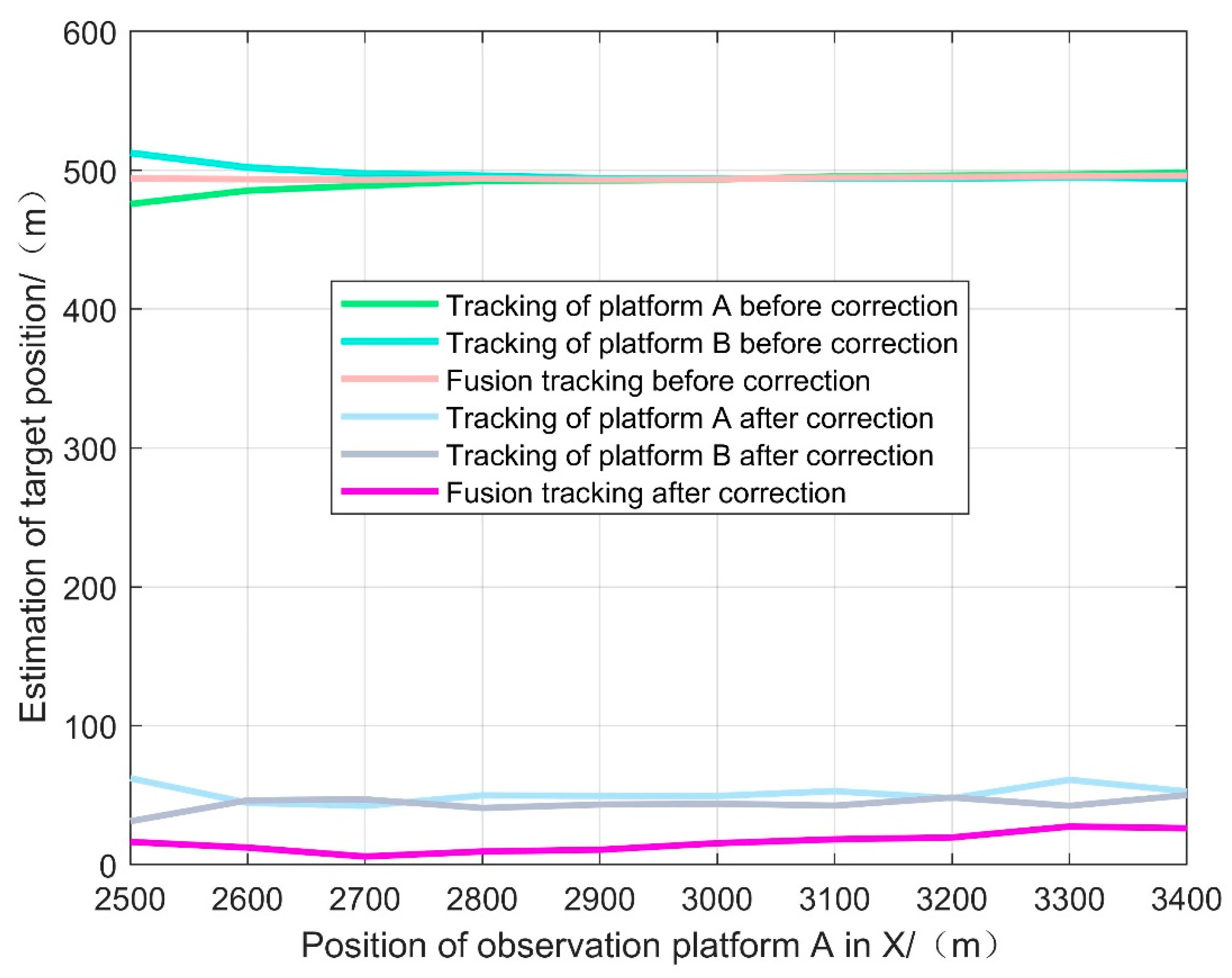
To further illustrate the effectiveness of the proposed method, the positions of the observation platforms are changed, and UAVs A and B are set to move 900 m in the X direction, and the tracking effect at different observation positions is shown in Figure 7.

Figure 7.
Estimation error of the target position in different observation positions.
Figure 7 shows that the new method can also obtain good position estimation results when constantly changing the observation positions, which proves the robustness of the method. Changes in the observed array position have a small effect on the tracking error as long as the application conditions are met. The result shows that the proposed method is applicable to a certain large range.
4.2. Practical Experiment
To further verify the effectiveness of the algorithm, an on-lake experiment was conducted.
4.2.1. Introduction to the Practical Experiment
The experimental system consists of an information processor, two radars, combined navigation equipment and RTK. Two small boats equipped with angular reflectors are used as the cooperative platform and target, respectively, in the experiment, and two radars are used to simulate two UAVs for cooperative observation of the target and cooperative platform.
4.2.2. Practical Experiment Result
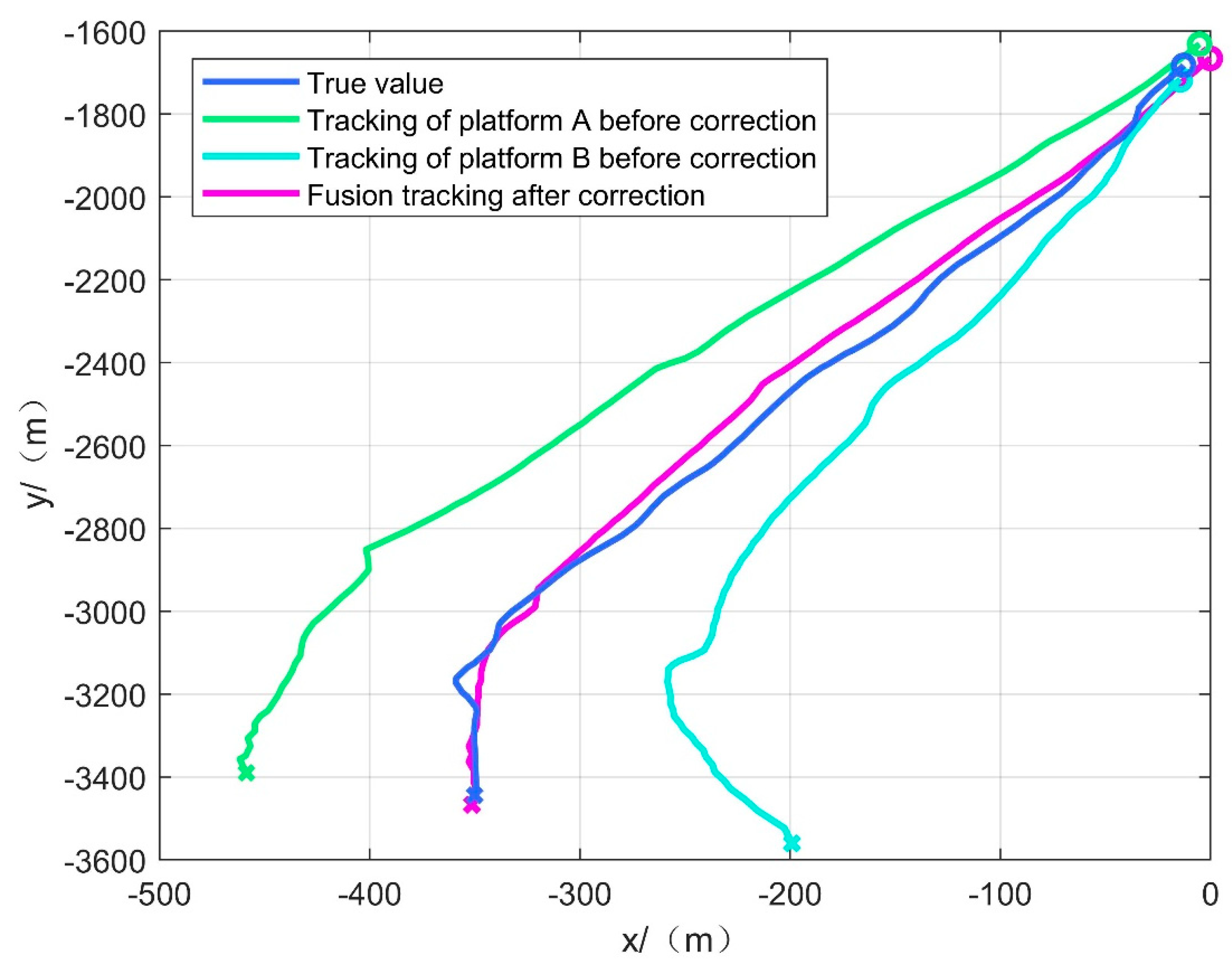
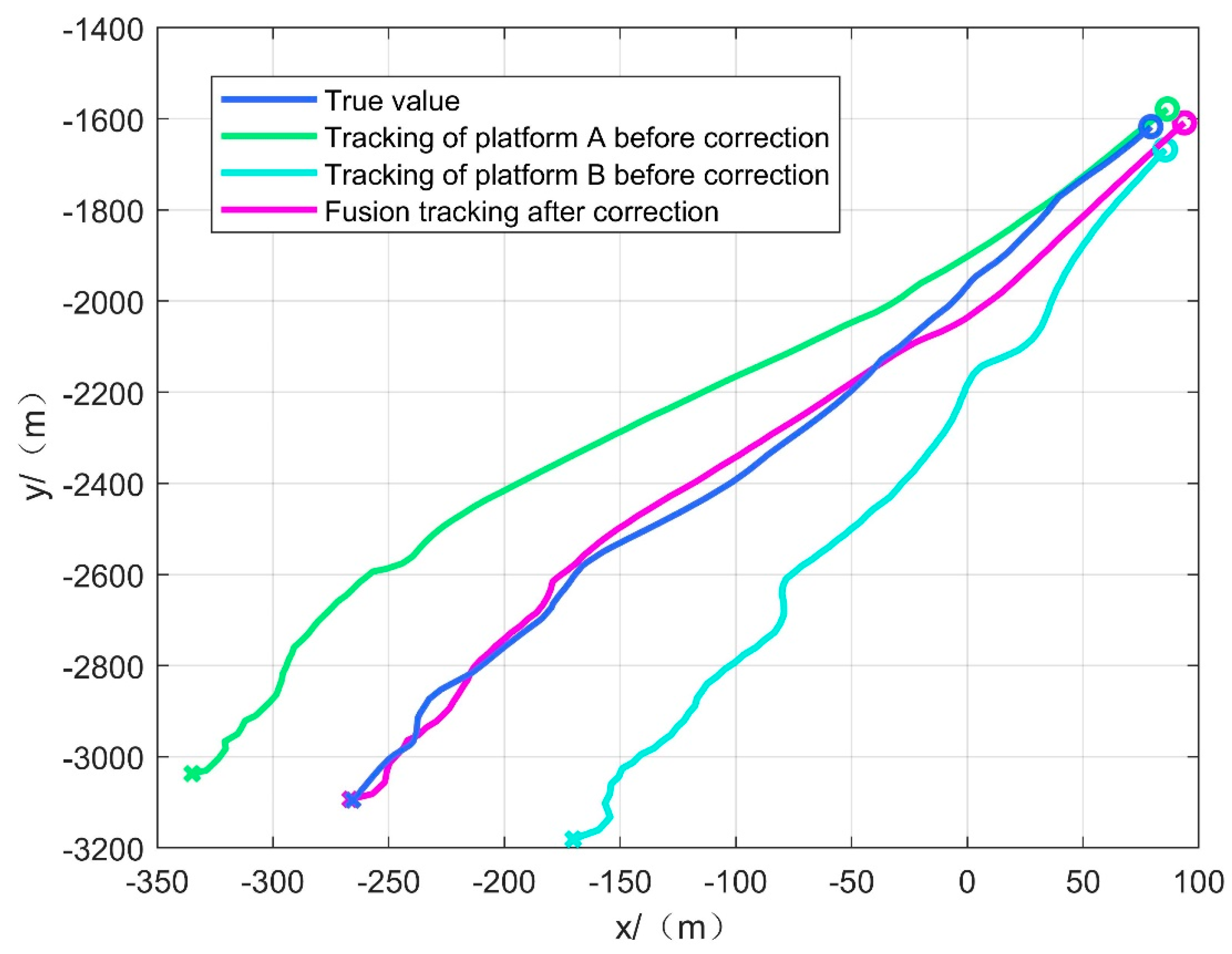
The proposed method is used to process the data collected in the experiments. The actual tracking effect of scenarios two and three is shown in Figure 8 and Figure 9. Table 5 and Table 6 show the position estimation error of scenarios two and three.

Figure 8.
Tracking effect of scenario two.
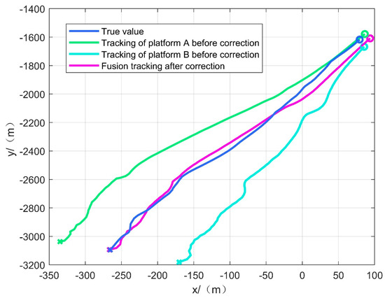
Figure 9.
Tracking effect of scenario three.
Table 5.
Position estimation error for scenario two.
Table 6.
Position estimation error for scenario three.
From Figure 8 and Figure 9, it can be seen that in the practical experiment on the lake, corrected fusion tracking is better than the uncorrected single-platform tracking effect. The corrected fusion tracking effect is more than five times better than the uncorrected single-platform tracking effect and can maintain stable tracking of the target. The result illustrates the feasibility of the proposed spatial registration method in the environment lacking geodetic coordinate information of the observation platform. The experiments prove its effectiveness in practical applications, and the proposed method can be used as a quick tracking method in emergency situations.
5. Conclusions
This paper proposes a spatial registration method for multi-UAVs based on a cooperative platform, which effectively reduces the impact of UAV observation systematic error and attitude systematic error on target tracking accuracy in a geodesic coordinate information-free environment. The method can be applied to situations where UAVs and cooperative platforms are in close proximity to each other. The proposed method is 90% effective in reducing systematic errors in simulation experiments. The corrected fusion tracking effect is more than five times better than the uncorrected single-platform tracking effect in the practical experiment. Both the simulation experiment and the practical experiment verify the effectiveness of the algorithm. The proposed method provides an emergency maritime target tracking method with certain engineering application value in the case of a lack of the geodetic coordinate information on the observation platform. In the future, we will conduct further research on the target tracking method in conjunction with the proposed spatial registration method and consider the effect of the reliability of the UAV.
Author Contributions
Conceptualization, J.X. and Q.D.; formal analysis, Q.D.; methodology, F.L.; project administration, Q.D. and F.L.; software, Q.D.; writing—original draft, Q.D. and F.L.; writing—review and editing, Q.D. and F.L. All authors have read and agreed to the published version of the manuscript.
Funding
This research received no external funding.
Institutional Review Board Statement
Not applicable.
Informed Consent Statement
Not applicable.
Data Availability Statement
Not applicable.
Conflicts of Interest
The authors declare no conflict of interest.
Appendix A
Approximate first-order Taylor expansion
where
Substitute Equations (1)–(6)
where
References
- Leung, H.; Blanchette, M.; Gault, K. Comparison of registration error correction techniques for air surveillance radar network. Proc. SPIE—Int. Soc. Opt. Eng. 1995, 2, 211–214. [Google Scholar]
- Cai, J.; Huang, P.; Zhang, B.; Wang, D. A TSR Visual Servoing System Based on a Novel Dynamic Template Matching Method. Sensors 2015, 15, 32152–32167. [Google Scholar] [CrossRef]
- Pfeifer, T.; Lange, S.; Protzel, P. Advancing Mixture Models for Least Squares Optimization. IEEE Robot. Autom. Lett. 2021, 6, 3941–3948. [Google Scholar] [CrossRef]
- Wei, Z.; Wei, S.; Luo, F.; Yang, S.; Wang, J. A Maximum Likelihood Registration Algorithm for Moving Dissimilar Sensors. In Proceedings of the IEEE 8th Joint International Information Technology and Artificial Intelligence Conference (ITAIC), Chongqing, China, 24–26 May 2019. [Google Scholar]
- Zhao, S.; Yi, M.; Liu, Z. Cooperative Anti-Deception Jamming in a Distributed Multiple-Radar System under Registration Errors. Sensors 2022, 22, 7216. [Google Scholar] [CrossRef]
- Da, K.; Li, T.; Zhu, Y.; Fu, Q. A Computationally Efficient Approach for Distributed Sensor Localization and Multitarget Tracking. IEEE Commun. Lett. 2020, 24, 335–338. [Google Scholar] [CrossRef]
- Belfadel, D.; Bar-Shalom, Y.; Willett, P. Single Space Based Sensor Bias Estimation Using a Single Target of Opportunity. IEEE Trans. Aerosp. Electron. Syst. 2020, 56, 1676–1684. [Google Scholar] [CrossRef]
- Lu, Z.-H.; Zhu, M.-Y.; Ye, Q.-W.; Zhou, Y. Performance analysis of two EM-based measurement bias estimation processes for tracking systems. Front. Inf. Technol. Electron. Eng. 2018, 19, 1151–1165. [Google Scholar] [CrossRef]
- Li, D.; Wu, D.; Lou, P. Exact Least Square Registration Algorithm for Multiple Dissimilar Sensors. In Proceedings of the 10th International Symposium on Computational Intelligence and Design (ISCID), Hangzhou, China, 9–10 December 2017; pp. 338–341. [Google Scholar]
- Pu, W.; Liu, Y.; Yan, J.; Zhou, S.; Liu, H. A two-stage optimization approach to the asynchronous multi-sensor registration problem. In Proceedings of the IEEE International Conference on Acoustics, Speech and Signal Processing (ICASSP), New Orleans, LA, USA, 5–9 March 2017. [Google Scholar]
- Shang, J.; Yao, Y. Approach of system error registration for two-station coast radars for sea surface monitoring. J. Eng. 2019, 2019, 7721–7725. [Google Scholar] [CrossRef]
- Lu, X.; Xie, Y.; Zhou, J. Improved Spatial Registration and Target Tracking Method for Sensors on Multiple Missiles. Sensors 2018, 18, 1723. [Google Scholar] [CrossRef] [PubMed]
- Drummond, O.E.; Belfadel, D.; Osborne, R.W.; Bar-Shalom, Y.; Teichgraeber, R.D. A minimalist approach to bias estimation for passive sensor measurements with targets of opportunity. In Proceedings of the Signal and Data Processing of Small Targets 2013, San Diego, CA, USA, 25–29 August 2013. [Google Scholar]
- Zhu, H.-M.; Jia, Z.-R.; Wang, H.-Y.; Sui, S.-Y. UAV target localization method for different field-of-view auxiliary beacons. J. Natl. Univ. Def. Technol. 2019, 41, 12. [Google Scholar]
- Zhao, Y.-H.; Yuan, F.; Ding, Z.-L.; Li, J. Monte Carlo estimation of cooperative target-based attitude measurement system modeling and accuracy. J. Sci. Instrum. 2010, 8, 1873–1877. [Google Scholar]
- Nguyen, V.H.; Pyun, J.Y. Location detection and tracking of moving targets by a 2D IR-UWB radar system. Sensors 2015, 15, 6740–6762. [Google Scholar] [CrossRef]
- Julier, S.J.; Uhlmann, J.K.; Durrant-Whyte, H.F. A new approach for filtering nonlinear systems. In Proceedings of the 1995 American Control Conference-ACC′95, Seattle, WA, USA, 21–23 June 1995. [Google Scholar]
- Huang, Y.; Zhang, Y.; Xu, B.; Wu, Z.; Chambers, J.A. A New Adaptive Extended Kalman Filter for Cooperative Localization. IEEE Trans. Aerosp. Electron. Syst. 2018, 54, 353–368. [Google Scholar] [CrossRef]
- Deng, Z.; Yin, L.; Huo, B.; Xia, Y. Adaptive Robust Unscented Kalman Filter via Fading Factor and Maximum Correntropy Criterion. Sensors 2018, 18, 2406. [Google Scholar] [CrossRef] [PubMed]
- György, K.; Kelemen, A.; Dávid, L. Unscented Kalman Filters and Particle Filter Methods for Nonlinear State Estimation. Procedia Technol. 2014, 12, 65–74. [Google Scholar] [CrossRef]
- Arasaratnam, I.; Haykin, S. Cubature Kalman Filters. IEEE Trans. Autom. Control 2009, 54, 1254–1269. [Google Scholar] [CrossRef]
- Zhu, W.; Wang, W.; Yuan, G. An Improved Interacting Multiple Model Filtering Algorithm Based on the Cubature Kalman Filter for Maneuvering Target Tracking. Sensors 2016, 16, 805. [Google Scholar] [CrossRef] [PubMed]
- Jin, X.B.; Robert Jeremiah, R.J.; Su, T.L.; Bai, Y.T.; Kong, J.L. The New Trend of State Estimation: From Model-Driven to Hybrid-Driven Methods. Sensors 2021, 21, 2085. [Google Scholar] [CrossRef]
- Li, W.; Jia, Y.; Du, J.; Yu, F. Gaussian mixture PHD filter for multi-sensor multi-target tracking with registration errors. Signal Process. 2013, 93, 86–99. [Google Scholar] [CrossRef]
- Wu, W.; Jiang, J.; Liu, W.; Feng, X.; Gao, L.; Qin, X. Augmented state GM-PHD filter with registration errors for multi-target tracking by Doppler radars. Signal Process. 2016, 120, 117–128. [Google Scholar] [CrossRef]
- He, X.; Liu, G. Augmented state PHD filter for extended target tracking with bias compensation. Optik 2018, 160, 203–213. [Google Scholar] [CrossRef]
- Jain, R.; Dhingra, S.; Joshi, K.; Rana, A.K.; Goyal, N. Enhance traffic flow prediction with Real-Time Vehicle Data Integration. J. Auton. Intell. 2023, 6. [Google Scholar] [CrossRef]
- Verma, V.; Gupta, D.; Gupta, S.; Uppal, M.; Anand, D.; Ortega-Mansilla, A.; Alharithi, F.S.; Almotiri, J.; Goyal, N. A Deep Learning-Based Intelligent Garbage Detection System Using an Unmanned Aerial Vehicle. Symmetry 2022, 14, 960. [Google Scholar] [CrossRef]
- Xiong, H.; Mai, Z.; Tang, J.; He, F. Robust GPS/INS/DVL Navigation and Positioning Method Using Adaptive Federated Strong Tracking Filter Based on Weighted Least Square Principle. IEEE Access 2019, 7, 26168–26178. [Google Scholar] [CrossRef]
- Patoliya, J.; Mewada, H.; Hassaballah, M.; Khan, M.A.; Kadry, S. A robust autonomous navigation and mapping system based on GPS and LiDAR data for unconstraint environment. Earth Sci. Inform. 2022, 15, 2703–2715. [Google Scholar] [CrossRef]
- Li, F.; Chang, L. MEKF with Navigation Frame Attitude Error Parameterization for INS/GPS. IEEE Sens. J. 2019, 20, 1536–1549. [Google Scholar] [CrossRef]
- Shen, H.; Zong, Q.; Lu, H.; Zhang, X.; Tian, B.; He, L. A distributed approach for lidar-based relative state estimation of multi-UAV in GPS-denied environments. Chin. J. Aeronaut. 2022, 35, 59–69. [Google Scholar] [CrossRef]
- Sarras, I.; Marzat, J.; Bertrand, S.; Piet-Lahanier, H. Collaborative multiple micro air vehicles’ localization and target tracking in GPS-denied environment from range–velocity measurements. Int. J. Micro Air Veh. 2018, 10, 225–239. [Google Scholar] [CrossRef]
- Kim, Y.; Jung, W.; Bang, H. Visual Target Tracking and Relative Navigation for Unmanned Aerial Vehicles in a GPS-Denied Environment. Int. J. Aeronaut. Space Sci. 2014, 15, 258–266. [Google Scholar] [CrossRef]
- Tang, C.; Wang, Y.; Zhang, L.; Zhang, Y.; Song, H. Multisource Fusion UAV Cluster Cooperative Positioning Using Information Geometry. Remote Sens. 2022, 14, 5491. [Google Scholar] [CrossRef]
- Dai, Q.; Lu, F. A New Spatial Registration Algorithm of Aerial Moving Platform to Sea Target Tracking. Sensors 2023, 23, 6112. [Google Scholar] [CrossRef] [PubMed]

Disclaimer/Publisher’s Note: The statements, opinions and data contained in all publications are solely those of the individual author(s) and contributor(s) and not of MDPI and/or the editor(s). MDPI and/or the editor(s) disclaim responsibility for any injury to people or property resulting from any ideas, methods, instructions or products referred to in the content. |
© 2023 by the authors. Licensee MDPI, Basel, Switzerland. This article is an open access article distributed under the terms and conditions of the Creative Commons Attribution (CC BY) license (https://creativecommons.org/licenses/by/4.0/).